WO2022230439A1 - コネクタ - Google Patents
コネクタ Download PDFInfo
- Publication number
- WO2022230439A1 WO2022230439A1 PCT/JP2022/012617 JP2022012617W WO2022230439A1 WO 2022230439 A1 WO2022230439 A1 WO 2022230439A1 JP 2022012617 W JP2022012617 W JP 2022012617W WO 2022230439 A1 WO2022230439 A1 WO 2022230439A1
- Authority
- WO
- WIPO (PCT)
- Prior art keywords
- core wire
- terminal
- connector
- wall
- connector housing
- Prior art date
- Legal status (The legal status is an assumption and is not a legal conclusion. Google has not performed a legal analysis and makes no representation as to the accuracy of the status listed.)
- Ceased
Links
Images


Classifications
-
- H—ELECTRICITY
- H01—ELECTRIC ELEMENTS
- H01R—ELECTRICALLY-CONDUCTIVE CONNECTIONS; STRUCTURAL ASSOCIATIONS OF A PLURALITY OF MUTUALLY-INSULATED ELECTRICAL CONNECTING ELEMENTS; COUPLING DEVICES; CURRENT COLLECTORS
- H01R4/00—Electrically-conductive connections between two or more conductive members in direct contact, i.e. touching one another; Means for effecting or maintaining such contact; Electrically-conductive connections having two or more spaced connecting locations for conductors and using contact members penetrating insulation
- H01R4/10—Electrically-conductive connections between two or more conductive members in direct contact, i.e. touching one another; Means for effecting or maintaining such contact; Electrically-conductive connections having two or more spaced connecting locations for conductors and using contact members penetrating insulation effected solely by twisting, wrapping, bending, crimping, or other permanent deformation
-
- H—ELECTRICITY
- H01—ELECTRIC ELEMENTS
- H01R—ELECTRICALLY-CONDUCTIVE CONNECTIONS; STRUCTURAL ASSOCIATIONS OF A PLURALITY OF MUTUALLY-INSULATED ELECTRICAL CONNECTING ELEMENTS; COUPLING DEVICES; CURRENT COLLECTORS
- H01R13/00—Details of coupling devices of the kinds covered by groups H01R12/70 or H01R24/00 - H01R33/00
- H01R13/40—Securing contact members in or to a base or case; Insulating of contact members
- H01R13/42—Securing in a demountable manner
- H01R13/436—Securing a plurality of contact members by one locking piece or operation
- H01R13/4367—Insertion of locking piece from the rear
- H01R13/4368—Insertion of locking piece from the rear comprising a temporary and a final locking position
-
- H—ELECTRICITY
- H01—ELECTRIC ELEMENTS
- H01R—ELECTRICALLY-CONDUCTIVE CONNECTIONS; STRUCTURAL ASSOCIATIONS OF A PLURALITY OF MUTUALLY-INSULATED ELECTRICAL CONNECTING ELEMENTS; COUPLING DEVICES; CURRENT COLLECTORS
- H01R13/00—Details of coupling devices of the kinds covered by groups H01R12/70 or H01R24/00 - H01R33/00
- H01R13/46—Bases; Cases
- H01R13/502—Bases; Cases composed of different pieces
-
- H—ELECTRICITY
- H01—ELECTRIC ELEMENTS
- H01R—ELECTRICALLY-CONDUCTIVE CONNECTIONS; STRUCTURAL ASSOCIATIONS OF A PLURALITY OF MUTUALLY-INSULATED ELECTRICAL CONNECTING ELEMENTS; COUPLING DEVICES; CURRENT COLLECTORS
- H01R13/00—Details of coupling devices of the kinds covered by groups H01R12/70 or H01R24/00 - H01R33/00
- H01R13/62—Means for facilitating engagement or disengagement of coupling parts or for holding them in engagement
- H01R13/629—Additional means for facilitating engagement or disengagement of coupling parts, e.g. aligning or guiding means, levers, gas pressure electrical locking indicators, manufacturing tolerances
- H01R13/631—Additional means for facilitating engagement or disengagement of coupling parts, e.g. aligning or guiding means, levers, gas pressure electrical locking indicators, manufacturing tolerances for engagement only
-
- H—ELECTRICITY
- H01—ELECTRIC ELEMENTS
- H01R—ELECTRICALLY-CONDUCTIVE CONNECTIONS; STRUCTURAL ASSOCIATIONS OF A PLURALITY OF MUTUALLY-INSULATED ELECTRICAL CONNECTING ELEMENTS; COUPLING DEVICES; CURRENT COLLECTORS
- H01R13/00—Details of coupling devices of the kinds covered by groups H01R12/70 or H01R24/00 - H01R33/00
- H01R13/62—Means for facilitating engagement or disengagement of coupling parts or for holding them in engagement
- H01R13/639—Additional means for holding or locking coupling parts together, after engagement, e.g. separate keylock, retainer strap
-
- H—ELECTRICITY
- H01—ELECTRIC ELEMENTS
- H01R—ELECTRICALLY-CONDUCTIVE CONNECTIONS; STRUCTURAL ASSOCIATIONS OF A PLURALITY OF MUTUALLY-INSULATED ELECTRICAL CONNECTING ELEMENTS; COUPLING DEVICES; CURRENT COLLECTORS
- H01R4/00—Electrically-conductive connections between two or more conductive members in direct contact, i.e. touching one another; Means for effecting or maintaining such contact; Electrically-conductive connections having two or more spaced connecting locations for conductors and using contact members penetrating insulation
- H01R4/28—Clamped connections, spring connections
- H01R4/50—Clamped connections, spring connections utilising a cam, wedge, cone or ball also combined with a screw
- H01R4/5066—Clamped connections, spring connections utilising a cam, wedge, cone or ball also combined with a screw mounted in an insulating housing having a cover providing clamping force
-
- H—ELECTRICITY
- H01—ELECTRIC ELEMENTS
- H01R—ELECTRICALLY-CONDUCTIVE CONNECTIONS; STRUCTURAL ASSOCIATIONS OF A PLURALITY OF MUTUALLY-INSULATED ELECTRICAL CONNECTING ELEMENTS; COUPLING DEVICES; CURRENT COLLECTORS
- H01R11/00—Individual connecting elements providing two or more spaced connecting locations for conductive members which are, or may be, thereby interconnected, e.g. end pieces for wires or cables supported by the wire or cable and having means for facilitating electrical connection to some other wire, terminal, or conductive member, blocks of binding posts
- H01R11/03—Individual connecting elements providing two or more spaced connecting locations for conductive members which are, or may be, thereby interconnected, e.g. end pieces for wires or cables supported by the wire or cable and having means for facilitating electrical connection to some other wire, terminal, or conductive member, blocks of binding posts characterised by the relationship between the connecting locations
- H01R11/05—Individual connecting elements providing two or more spaced connecting locations for conductive members which are, or may be, thereby interconnected, e.g. end pieces for wires or cables supported by the wire or cable and having means for facilitating electrical connection to some other wire, terminal, or conductive member, blocks of binding posts characterised by the relationship between the connecting locations the connecting locations having different types of direct connections
Definitions
- This disclosure relates to connectors.
- Patent Document 1 Japanese Patent Application Laid-Open No. 2019-145208
- the female terminal includes a terminal body having a deformable upper connecting piece and a lower connecting piece extending in the extension direction, and a sliding portion movable in the extension direction with respect to the terminal body.
- the upper contact portion and the lower contact portion provided on the slide portion contact the upper connection piece and the lower connection piece.
- Patent Literature 1 listed below describes a connector including a connector housing that accommodates the female terminals and a rear holder that is attached to the rear end portion of the connector housing in the extending direction, as a connector having the female terminals. .
- the above connector is manufactured as follows. First, the female terminals are accommodated in the connector housing, and the rear holder is assembled to the rear end portion of the connector housing. In this state, the rear holder is held at the temporary locking position with respect to the connector housing. Next, an electric wire is inserted through the insertion hole of the rear holder, and the core wire of the electric wire is inserted inside the female terminal. At this time, the core wire is arranged between the upper connecting piece and the lower connecting piece. Subsequently, by moving the slide portion forward with respect to the terminal body, the upper contact portion and the lower contact portion press the upper connecting piece and the lower connecting piece against the core wire, thereby connecting the female terminal and the electric wire. is done. Finally, the connector is manufactured by moving the rear holder forward from the temporary locking position to the final locking position to retain the female terminal in the connector housing.
- the guide portion for guiding the insertion of the core wire into the female terminal on the inner wall of the insertion hole of the rear holder.
- the guide portion is configured to have a shape positioned more inwardly of the insertion hole toward the front, and guides the core wire into the female terminal by making sliding contact with the core wire.
- the guide portion may interfere with the insulation coating of the electric wire, preventing the rear holder from being moved rearward. That is, there may be cases where the rear holder cannot be removed from the connector. Therefore, for example, it becomes difficult to repair the female terminal.
- a connector of the present disclosure has a core wire and an insulating coating covering the outer periphery of the core wire, and is a connector connected to an electric wire extending in the front-rear direction, wherein the terminal is connected to the core wire, and the terminal is accommodated inside. and a rear holder attached to a rear portion of the connector housing, wherein the terminal is electrically connected to a core wire insertion opening into which the core wire is inserted from the rear and the core wire.
- the connector includes a guide portion for guiding insertion, wherein the guide portion is composed of a first inner wall provided on the connector housing and a second inner wall provided on the rear holder.
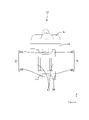
- FIG. 1 is a perspective view of a connector according to a first embodiment
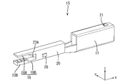
- FIG. FIG. 2 is a side view of the terminal with the sliding portion arranged at the spaced position.
- FIG. 3 is a rear view of the terminal with the sliding portion arranged at the spaced position.
- FIG. 4 is a side view of the terminal with the sliding portion arranged at the pressing position.
- FIG. 5 is a perspective view of a terminal body.
- FIG. 6 is a perspective view of the slide portion.
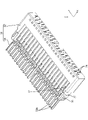
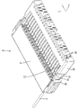
- FIG. 7 is a perspective view of the connector housing.
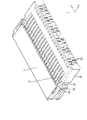
- FIG. 8 is a perspective view showing a state in which the terminals are housed in the connector housing.
- FIG. 9 is a perspective view showing a state in which the connector housing holds the rear holder at the temporary locking position.
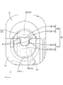
- FIG. 10 is a rear view showing a state in which the rear holder is held by the connector housing at the temporary locking position.
- 11 is an enlarged view of FIG. 10.
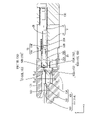
- FIG. 12 is a cross-sectional view taken along the line AA of FIG. 10.
- FIG. 13 is a cross-sectional view taken along the line BB of FIG. 12.
- FIG. 14 is a cross-sectional view showing a state in which the electric wire is inserted in cross section AA of FIG. 10.
- FIG. 15 is a cross-sectional view showing a step of moving the sliding portion from the separated position to the pressing position on the AA cross section of FIG. 10.
- FIG. 16 is a cross-sectional view showing a state in which the rear holder is held at the full locking position by the connector housing in cross section AA of FIG. 10.
- FIG. 17 is a perspective view showing a state in which the rear holder has moved rearward from the temporary locking position with respect to the connector housing.
- 18 is a cross-sectional view showing a state in which the rear holder has moved rearward from the temporary locking position with respect to the connector housing on the AA cross section of FIG. 10.
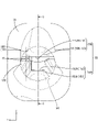
- FIG. FIG. 19 is an enlarged rear view showing a state in which the rear holder is held at the temporary locking position by the connector housing according to the second embodiment;
- 20 is a cross-sectional view taken along line CC of FIG. 19.
- FIG. 21 is a cross-sectional view taken along line DD of FIG. 20.
- FIG. 22 is a cross-sectional view taken along the line EE of FIG. 20.
- FIG. 23 is a cross-sectional view of the connector along the CC cross section of FIG. 19.
- FIG. 19 is a cross-sectional view of the connector along the CC cross section of FIG. 19.
- a connector of the present disclosure has a core wire and an insulating coating covering the outer periphery of the core wire, and is connected to an electric wire extending in the front-rear direction.
- a connector housing provided with a terminal accommodating portion to be accommodated therein, and a rear holder attached to a rear portion of the connector housing, wherein the terminal includes a core wire insertion opening into which the core wire is inserted from the rear, and an electrical terminal attached to the core wire.
- the connector housing and the rear holder constitute an electric wire insertion portion into which the electric wire is inserted, and the electric wire insertion portion is adapted to insert the terminal accommodated inside the terminal accommodation portion into the core wire insertion opening.
- a guide portion for guiding insertion of the core wire is provided, and the guide portion is composed of a first inner wall provided on the connector housing and a second inner wall provided on the rear holder.
- the insertion of the core wire into the core wire insertion opening of the terminal accommodated in the connector housing can be guided by the guide portion. Further, since the guide portion is composed of the first inner wall provided on the connector housing and the second inner wall provided on the rear holder, the rear holder can be easily removed from the connector housing.
- the minimum opening diameter of the guide portion is smaller than the opening diameter of the core wire insertion opening and larger than the diameter of the core wire.
- the connector housing has an electric wire receiving space behind the first inner wall, and the electric wires are accommodated in the electric wire receiving space.
- the coating is prevented from interfering with the second inner wall.
- At least one of the first inner wall and the second inner wall preferably has a mortar-shaped portion arranged so that the opening diameter of the guide portion decreases toward the front.
- the mortar-shaped portion facilitates guiding the core wire into the core wire insertion opening.
- At least one of the first inner wall and the second inner wall is disposed so that the opening diameter of the guide portion decreases toward the front, and has a planar shape that intersects an axis extending in the front-rear direction.
- At least one of the connector housing and the rear holder has an engaging surface that engages the rear end of the terminal, and the inclined surface and the engaging surface are arranged side by side in the front-rear direction. It is preferable that
- the terminal includes a terminal main body including the electrical connection portion, and a sliding portion having the core wire insertion opening and the pressing portion and being movable in the front-rear direction with respect to the terminal main body. is preferred.
- the electric connection portion can be pressed against the electric wire, and the electric wire and the terminal can be electrically connected.
- the slide portion is disposed at a pressing position where the electrical connection portion is pressed against the core wire by the pressing portion, and behind the pressing portion, and the pressing portion is separated from the electrical connection portion. It is preferably movable between the separated position and.
- the electric wire and the terminal can be electrically connected by moving the slide portion from the separated position to the pressing position with respect to the terminal body.
- the rear holder is movable in the front-rear direction with respect to the connector housing.
- the rear holder is movable between a final locking position disposed ahead of the temporary locking position, and the rear holder is disposed at the pressing position while the rear holder is disposed at the final locking position. It is preferable to have a locking surface that locks onto the rear end of the slide portion.
- the rear holder is movable in the longitudinal direction between the temporary locking position and the final locking position. can be stopped to prevent the terminal from coming off.
- the slide portion is formed in a tubular shape extending in the front-rear direction. It is preferable that a guide portion is provided for guiding the core wire into the slide portion by sliding contact therewith.
- the core wire can be easily inserted into the slide portion by the guiding portion.
- the slide portion is provided with a jig abutment portion projecting outward, and the slide portion slides forward when the jig abutment portion is pressed from behind by the jig. It is preferable that
- the electric wire and the terminal can be electrically connected by bringing the jig into contact with the jig contact portion and pressing the sliding portion forward.
- Embodiment 1 of the present disclosure will be described with reference to FIGS. 1 to 18.
- FIG. In the following description, the direction indicated by arrow Z is upward, the direction indicated by arrow X is forward, and the direction indicated by arrow Y is leftward.
- a plurality of identical members only some members may be given reference numerals, and the reference numerals of other members may be omitted.
- the connector 10 As shown in FIG. 1, the connector 10 according to the present embodiment includes a terminal 12 connected to an end of an electric wire 11, a connector housing 30 having a terminal accommodating portion 29 for accommodating the terminal 12, and a rear side of the connector housing 30. and a rear holder 31 attached to the part.
- the electric wire 11 is arranged extending in the front-rear direction.
- the electric wire 11 has a core wire 13 surrounded by an insulating coating 14 made of an insulating synthetic resin.
- the core wire 13 is made of a conductive metal, and is a stranded wire obtained by twisting a plurality of metal wires, or a single metal wire.
- the insulating coating 14 is removed and the core wire 13 is exposed.
- the terminal 12 is made of metal, and as shown in FIGS. 2 and 4, includes a terminal body 15 and a sliding portion 16 that can move forward and backward with respect to the terminal body 15 .
- the terminal main body 15 and the slide portion 16 are formed into predetermined shapes by known techniques such as press working, cutting, and casting. Any metal such as copper, copper alloy, aluminum, aluminum alloy, and stainless steel can be appropriately selected as the metal forming the terminal main body 15 and the slide portion 16 as necessary.
- a plating layer may be formed on the surfaces of the terminal body 15 and the slide portion 16 . Any metal such as tin, nickel, silver, or the like can be appropriately selected as the metal forming the plating layer.
- the front portion of the terminal main body 15 is a connecting tube portion 17 in the shape of a rectangular tube extending in the front-rear direction.
- a plate-like mating terminal (not shown) can be inserted into the connecting tube portion 17 from the front.
- An elastic contact piece (not shown) is disposed inside the connecting tube portion 17, and the mating terminal inserted into the connecting tube portion 17 contacts the elastic contact piece.
- a lance 21 is formed on the front side of the upper wall of the connecting tube portion 17 so as to protrude upward in the shape of a mountain.
- a base portion 20 having a square tubular shape is provided behind the connecting tubular portion 17 .
- a side wall of the base 20 is formed with a locking projection 28 projecting outward.
- An electrical connection portion 18 is provided at the rear end portion of the base portion 20 .
- the electrical connection portion 18 includes an upper connection piece 18A extending rearward from the rear end of the upper wall of the base portion 20 and a rear end of the lower wall of the base portion 20 extending rearward. and a lower connection piece 18B.
- the upper connection piece 18A and the lower connection piece 18B are elongated in the front-rear direction, and their lengths in the front-rear direction are approximately the same.
- the upper connection piece 18A and the lower connection piece 18B are formed so as to be elastically deformable in the vertical direction with the rear end portion of the base portion 20 as a fulcrum.
- the lower surface of the upper connection piece 18A and the upper surface of the lower connection piece 18B sandwich the core wire 13 so that the electric wire 11 and the terminal body 15 can be electrically connected.
- the lower surface of the upper connection piece 18A is provided with an upper holding protrusion 23A projecting downward at a position forward of the rear end.
- a lower holding protrusion 23B protruding upward is provided at the rear end portion of the upper surface of the lower connection piece 18B.
- the upper holding protrusion 23A and the lower holding protrusion 23B are provided at positions shifted in the front-rear direction.
- the slide portion 16 has a rectangular tubular shape extending in the front-rear direction. As shown in FIG. 3, the cross section of the shape of the inside of the slide portion 16 is formed to be the same as or slightly larger than the cross section of the shape of the outside of the region of the terminal body 15 where the electrical connection portion 18 is provided. As a result, the slide portion 16 can be fitted onto the region of the terminal body 15 where the electrical connection portion 18 is provided.
- the slide portion 16 is provided with a pressing portion 25 .
- a pressing portion 25 an upper pressing portion 25A that protrudes downward is arranged on the lower surface of the upper wall of the slide portion 16, and a lower pressing portion that protrudes upward is arranged on the upper surface of the lower wall of the slide portion 16. 25B are arranged.
- the side wall of the slide portion 16 has a temporary locking receiving portion 26 opened at a position near the front end portion. Further, a main locking receiving portion 27 is opened in the side wall of the slide portion 16 at a position rearward of the temporary locking receiving portion 26 .
- the temporary locking receiving portion 26 and the final locking receiving portion 27 can be elastically locked with the locking protrusion 28 of the terminal main body 15 .
- the upper pressing portion 25A presses the upper connecting piece 18A from above, thereby causing the upper connecting piece 18A to elastically move downward. It is designed to transform.
- the lower connecting piece 18B is elastically deformed upward when the lower pressing portion 25B presses the lower connecting piece 18B from below.
- the core wire 13 is arranged in the space between the upper connection piece 18A and the lower connection piece 18B in a state of being extended in the front-rear direction, and the sliding portion 16 is held at the pressing position against the terminal body 15. In this state, the core wire 13 is vertically sandwiched between the elastically deformed upper connection piece 18A and the lower connection piece 18B.
- the upper holding protrusion 23A of the upper connecting piece 18A presses the core wire 13 from above, and the lower connecting piece 18B is pressed.
- the lower holding protrusion 23B presses the core wire 13 from below.
- the core wire 13 is pressed from above by the upper holding protrusion 23A and is pressed from below by the lower holding protrusion 23B which is displaced from the upper holding protrusion 23A in the front-rear direction. , is held in a bent state in the vertical direction. Thereby, the holding force of the core wire 13 in the terminal main body 15 can be improved.
- the front end portion of the slide portion 16 is provided with a jig contact portion 46 projecting upward from the upper wall as shown in FIGS.
- the jig 45 abuts against the jig abutting portion 46 from behind, and the slide portion 16 is pushed forward by the jig 45, thereby allowing the slide portion 16 to move forward.
- the rear end portion of the rectangular tubular slide portion 16 is a core wire insertion opening 54 for inserting the core wire 13 into the slide portion 16 .
- a pair of guiding portions 47 protruding inward of the slide portion 16 are provided on both left and right side walls at a position near the rear end portion of the slide portion 16 .
- the guiding portion 47 is formed to be narrower from the rear to the front.
- the core wire 13 is inserted through the core wire insertion opening 54 and slidably contacted with the inner surface of the guide portion 47, whereby the core wire 13 is guided into the slide portion 16 (see FIG. 14).
- the connector housing 30 is made of insulating synthetic resin and, as shown in FIGS. 7 and 8, includes a main body portion 32 having a substantially rectangular parallelepiped shape and a partition wall 34 extending rearward from the rear end of the main body portion 32. .
- a plurality of terminal accommodating portions 29 that accommodate the terminals 12 are provided in the body portion 32 .
- the terminal accommodating portions 29 extend in the front-rear direction and are spaced apart in the left-right direction.
- the terminal accommodating portions 29 are stacked vertically in two stages, and the upper terminal accommodating portion 29 and the lower terminal accommodating portion 29 are arranged at positions shifted in the horizontal direction.
- the number of terminal accommodating portions 29 is arbitrary, and the number of stages when they are stacked vertically is also arbitrary.
- the front end of the terminal accommodating portion 29 is open forward, so that the mating terminal can be inserted therein.
- the connector housing 30 is provided with locking walls 33 so as to correspond to the positions of the lances 21 of the terminals 12 when the terminals 12 are accommodated in the terminal accommodating portions 29 .
- the locking wall 33 locks the lance 21 and prevents the terminal 12 from coming out rearward.
- the front end portion of the connector housing 30 is formed with a front stop portion 40 that abuts on the front end portion of the terminal 12, as shown in FIG.
- the front stop portion 40 abuts on the terminal 12 so as to prevent the terminal 12 from slipping forward of the connector housing 30 when the terminal 12 is inserted into the terminal accommodating portion 29 .
- a temporary lock portion 36 and a full lock portion 37 are provided on the left and right side walls of the body portion 32 of the connector housing 30 so as to protrude outward.
- the temporary locking portion 36 is arranged near the rear end portion of the body portion 32
- the final locking portion 37 is arranged in front of the temporary locking portion 36 .
- the rear holder 31 is made of an insulating synthetic resin, and has a box shape opening in the front-rear direction as shown in FIGS. 1, 9 and 10 .
- the rear holder 31 is fitted onto the rear half of the connector housing 30 .
- Lock receiving portions 38 are provided at positions near the front end portion of the left and right side walls of the rear holder 31 .
- the lock receiving portion 38 has a substantially gate shape. The lock receiving portion 38 engages with the temporary locking lock portion 36 and the final locking lock portion 37 of the connector housing 30 .
- the rear holder 31 is held at a temporary locking position with respect to the connector housing 30 by locking the temporary locking lock portion 36 of the connector housing 30 and the lock receiving portion 38 of the rear holder 31 . be. Further, as shown in FIG. 1, the rear holder 31 is brought to the full locking position with respect to the connector housing 30 by locking the full locking lock portion 37 of the connector housing 30 and the lock receiving portion 38 of the rear holder 31 . retained.
- the rear holder 31 has a hood portion 41 that opens forward, into which the connector housing 30 is fitted.
- the front end of the receptacle 41 covers the terminals 12 arranged inside the connector housing 30 from the outside.
- the front side of the receptacle 41 is provided with an engaging surface 43 that engages with the rear end portion of the terminal 12 .
- the wire insertion portion 50 includes a large diameter portion 51 having a large opening diameter, a small diameter portion 52 having an opening diameter smaller than that of the large diameter portion 51, and a reduced diameter portion continuously connecting the large diameter portion 51 and the small diameter portion 52. a portion 53;
- the small diameter portion 52 is arranged at the front end portion of the wire insertion portion 50 .
- the reduced diameter portion 53 is arranged at a position closer to the front end portion of the wire insertion portion 50, and is formed so that the opening diameter becomes smaller toward the front.
- the large diameter portion 51 is provided in a portion from the rear end of the reduced diameter portion 53 to the rear end of the wire insertion portion 50 .
- the insulating coating 14 of the electric wire 11 can be accommodated inside the large-diameter portion 51 .
- the core wire 13 of the electric wire 11 can be accommodated inside the small diameter portion 52 .
- a guide portion 55 that guides insertion of the core wire 13 into the core wire insertion opening 54 of the terminal 12 is formed by the reduced diameter portion 53 and the small diameter portion 52 .
- the wire insertion portion 50 is composed of a first wire insertion portion 50A provided on the connector housing 30 side and a second wire insertion portion 50B provided on the rear holder 31 side. Since the rear holder 31 is arranged to cover the outside of the connector housing 30, the second wire insertion portion 50B is arranged on the upper side and the first wire insertion portion 50A is arranged on the lower side in the upper stage, and the first wire insertion portion 50A is arranged on the upper side in the lower stage. The second wire insertion portion 50B is arranged on the lower side of the insertion portion 50A.
- the configuration of the wire insertion portion 50 will be described based on the upper positional relationship.
- the guide portion 55 of the wire insertion portion 50 can move the core wire 13 of the wire 11 only when the rear holder 31 is held at the temporary locking position and the slide portion 16 is placed at the spaced position. into the core wire insertion opening 54 of the terminal 12.
- the guide portion 55 is not constructed (see FIGS. 16 and 18).
- first wire insertion portions 50A are provided above and below the partition wall 34 .
- the first wire insertion portions 50A are groove-shaped extending in the front-rear direction and are arranged side by side at equal intervals in the left-right direction.
- Each first wire insertion portion 50A is formed so as to be continuous with each terminal accommodating portion 29 .
- the first wire insertion portion 50A includes a first large diameter portion 51A arranged on the rear side, a first small diameter portion 52A arranged on the front end, a first large diameter portion 51A and a first wire insertion portion 50A. 53 A of 1st reduced diameter parts which connect 52 A of 1 small diameter parts, and.
- the first large diameter portion 51A and the first small diameter portion 52A each have a substantially U-shaped constant cross-sectional shape.
- the first reduced diameter portion 53A has a substantially U-shaped cross section. As shown in FIG. 12, the first diameter-reduced portion 53A is formed such that the lateral and vertical dimensions thereof decrease toward the front. That is, the first reduced-diameter portion 53A is a mortar-shaped portion 56 arranged so as to approach the first small-diameter portion 52A toward the front.
- a first inner wall 55A of the connector housing 30 is composed of the first small diameter portion 52A and the first reduced diameter portion 53A (the mortar-shaped portion 56).
- the rear holder 31 has a second wire insertion portion 50B at a position facing the first wire insertion portion 50A in the vertical direction when the rear holder 31 is arranged at the temporary locking position.
- the second wire insertion portion 50B connects a second large diameter portion 51B arranged on the rear side, a second small diameter portion 52B arranged on the front end portion, and the second large diameter portion 51B and the second small diameter portion 52B. and a second reduced diameter portion 53B.
- the second large-diameter portion 51B has a substantially U-shaped constant cross-sectional shape and extends in the front-rear direction.
- the second small-diameter portion 52B is a flat surface perpendicular to the axis extending in the vertical direction.
- the second small diameter portion 52B is arranged to connect the second reduced diameter portion 53B and the locking surface 43 .
- the second reduced diameter portion 53B has a planar shape that intersects an axis extending in the front-rear direction, and has an inclined surface 57 positioned downward (upper in the lower stage) toward the front. Therefore, as shown in FIG. 13, the cross-sectional shape of the first reduced diameter portion 53A (the mortar-shaped portion 56) is U-shaped, while the cross-sectional shape of the second reduced diameter portion 53B (inclined surface 57) is a straight line. shape. As shown in FIG. 12, the second inner wall 55B of the rear holder 31 is formed by the second small diameter portion 52B and the second reduced diameter portion 53B (inclined surface 57).
- the first inner wall 55A and the second inner wall 55B constitute the guide portion 55 while the rear holder 31 is held at the temporary locking position.
- the guide portion 55 includes a reduced diameter portion 53 and a small diameter portion 52 whose width is narrowed toward the front.
- the minimum opening diameter of the guide portion 55 is smaller than the opening diameter of the core wire insertion opening 54, and the guide portion 55 is arranged so as to cover most of the core wire insertion opening 54 when viewed from the back.
- the minimum opening diameter of the guide portion 55 is larger than the diameter of the core wire 13 . Therefore, the guide portion 55 can guide the core wire 13 into the core wire insertion opening 54 by being in sliding contact with the core wire 13 .
- the curved mortar-shaped portion 56 slides on the core wire 13 and guides the core wire 13 into the first small diameter portion 52A (see FIG. 11).
- the second diameter-reduced portion 53B is an inclined surface 57 arranged downward toward the front (rearward in the direction perpendicular to the paper surface), so that it slides on the core wire 13 and guides the core wire 13 downward.
- the second reduced-diameter portion 53B guides the core wire 13 only downward and cannot guide it in the left-right direction.
- the guide portion 55 as a whole sufficiently exhibits the guide function of guiding the core wire 13 into the core wire insertion opening 54 .
- the slide portion 16 is provided with the guiding portion 47 , the core wire 13 is also guided into the terminal 12 by the guiding portion 47 .
- the second reduced diameter portion 53B is It is arranged side by side in the front-rear direction with the locking surface 43 that locks onto the rear end of the terminal 12 . Therefore, for example, when the wire 11 is pulled backward, the portion of the rear holder 31 from the locking surface 43 to the second reduced diameter portion 53B is subjected to shear stress by the rear end portion of the terminal 12 .
- the second diameter-reduced portion 53B is formed as a planar inclined surface 57, it is easier to increase the shear cross-sectional area than in the case of a curved surface such as the first diameter-reduced portion 53A.
- the vertical dimension of the large-diameter portion 51 is larger than the horizontal dimension.
- the vertical dimension of the first large diameter portion 51A on the connector housing 30 side is set to be the same as or slightly larger than the outer diameter of the electric wire 11 (the portion having the insulating coating 14). Therefore, as shown in FIG. 18, the connector housing 30 has a wire receiving space 58 capable of receiving the wire 11 inside the first large diameter portion 51A.
- a terminal main body 15 and a slide portion 16 are formed by a known method.
- the slide portion 16 is attached to the terminal body 15 from behind.
- the front edge of the slide portion 16 abuts against the locking projection 28 of the terminal body 15 from behind, and the side wall of the slide portion 16 is expanded and deformed.
- the sliding portion 16 is further pushed forward, the side wall of the sliding portion 16 is deformed back, and the temporary locking receiving portion 26 of the sliding portion 16 is locked to the locking projection 28 of the terminal main body 15 .
- Terminals 12 are thus obtained (see FIG. 2).
- the connector housing 30 and the rear holder 31 are formed by injection molding synthetic resin. After the terminals 12 are inserted into the terminal accommodating portions 29 of the connector housing 30 from behind (see FIG. 8), the rear holder 31 is attached to the rear end portion of the connector housing 30 from behind. Then, the lock receiving portion 38 of the rear holder 31 rides on the temporary locking portion 36 of the connector housing 30 while being elastically deformed. When the rear holder 31 is further pushed forward, the lock receiving portion 38 is restored and deformed, and the lock receiving portion 38 is elastically locked to the temporary lock portion 36 of the connector housing 30 . Thereby, the rear holder 31 is held at the temporary locking position with respect to the connector housing 30 (see FIGS. 9 and 12).
- the core wire 13 having a predetermined length is exposed.
- the front end of the core wire 13 is inserted into the wire insertion portion 50 from behind.
- the electric wire 11 is first placed in the large diameter portion 51 of the electric wire insertion portion 50 , and when the electric wire 11 is further pushed forward, the front end portion of the core wire 13 reaches the reduced diameter portion 53 .
- the front end portion of the core wire 13 is guided into the small-diameter portion 52 by slidingly contacting the reduced-diameter portion 53 .
- the front end portion of the core wire 13 is inserted into the core wire insertion opening 54 of the slide portion 16 from the front end of the small diameter portion 52 .
- the core wire 13 is guided into the core wire insertion opening 54 by the guide portion 55 (the reduced diameter portion 53 and the small diameter portion 52).
- the core wire 13 is also guided into the slide portion 16 by coming into contact with the guiding portion 47 of the slide portion 16 .
- the core wire 13 When the electric wire 11 is further pushed forward, as shown in FIG. 14, the core wire 13 enters the inside of the terminal main body 15 and is arranged at the position of the electrical connection portion 18 in the front-rear direction. That is, the core wire 13 passes through the space between the upper connection piece 18A and the lower connection piece 18B. In this state, the insulating coating 14 of the wire 11 is positioned inside the large diameter portion 51 of the wire insertion portion 50 .
- the jig 45 is pressed against the jig contact portion 46 from behind to move the sliding portion 16 forward relative to the terminal body 15 .
- the locking projection 28 of the terminal body 15 and the temporary locking receiving portion 26 of the slide portion 16 are disengaged, and the side wall of the slide portion 16 rides on the locking projection 28 and is expanded and deformed.
- the upper pressing portion 25A of the slide portion 16 contacts the upper connecting piece 18A of the terminal body 15 from above and presses it downward. Further, the lower pressing portion 25B of the slide portion 16 contacts the lower connecting piece 18B of the terminal body 15 from below and presses it upward. Thereby, the core wire 13 is sandwiched between the upper connection piece 18A and the lower connection piece 18B from above and below, and the electric wire 11 and the terminal 12 are electrically connected (see FIG. 16).
- the core wire 13 In a state in which the core wire 13 is sandwiched between the upper connection piece 18A and the lower connection piece 18B from above and below, the core wire 13 is held by the upper holding projection 23A of the upper connection piece 18A and the lower holding projection of the lower connection piece 18B. 23B, it is held in a state extended in the front-rear direction and in a state bent in the up-down direction. Thereby, the terminal 12 can firmly hold the core wire 13 (see FIG. 16).
- Repairing the terminal 12 means replacing the defective terminal 12 in the connector 10 with a new terminal 12 .
- the rear holder 31 is removed from the connector housing 30 .
- the lock receiving portion 38 of the rear holder 31 By bending the lock receiving portion 38 of the rear holder 31 outward, the locking with the main locking lock portion 37 and the temporary locking lock portion 36 is released, and the rear holder 31 is moved rearward (see FIG. 17).
- the space behind the terminal accommodating portion 29 can be used, so the core wire 13 led out from the terminal 12 to be repaired can be cut. , the terminal 12 to be repaired can be taken out from the terminal accommodating portion 29 . Subsequently, a new terminal 12 is accommodated in the terminal accommodating portion 29, and the connector 10 is constructed again in the same manner as in the manufacturing method described above.
- the guide portion 55 having a portion whose opening diameter is smaller than the outer diameter of the electric wire 11 is formed by a first inner wall 55A on the connector housing 30 side and a second inner wall 55B on the rear holder 31 side. and consists of Therefore, as shown in FIG. 18, when the rear holder 31 is moved rearward with respect to the connector housing 30, the second inner wall 55B moves rearward, but the position of the first inner wall 55A does not change. That is, since only the second inner wall 55B, which is a part of the guide portion 55, moves instead of the entire guide portion 55 moving relative to the electric wire 11, the insulating coating 14 of the electric wire 11 does not move with respect to the guide portion. It is difficult to interfere with 55.
- the wire receiving space 58 is provided behind the first inner wall 55A of the connector housing 30. Therefore, even if the rear holder 31 moves rearward, the wires 11 escapes into the wire receiving space 58, interference between the second inner wall 55B and the insulating coating 14 of the wire 11 is further suppressed. Therefore, in the connector 10, the rear holder 31 can be easily removed from the connector housing 30, and the above-described repair work of the terminals 12 can be performed successfully.
- a connector 10 according to the first embodiment has a core wire 13 and an insulating coating 14 covering the outer periphery of the core wire 13, and is connected to an electric wire 11 extending in the front-rear direction.
- Terminals 12 are connected to the core wire 13.
- a connector housing 30 having a terminal accommodating portion 29 for accommodating the terminal 12 therein, and a rear holder 31 attached to the rear portion of the connector housing 30, and the terminal 12 is provided with a core wire into which the core wire 13 is inserted from the rear.
- the insertion port 54 , the electrical connection portion 18 electrically connected to the core wire 13 , and the core wire 13 inserted through the core wire insertion port 54 and arranged at the position of the electrical connection portion 18 in the front-rear direction is pressed against the electrical connection portion 18 .
- the connector housing 30 and the rear holder 31 constitute an electric wire insertion portion 50 through which the electric wire 11 is inserted.
- a guide portion 55 for guiding the insertion of the core wire 13 into the core wire insertion opening 54 of the accommodated terminal 12 is provided. 55B.
- the insertion of the core wire 13 into the core wire insertion opening 54 of the terminal 12 accommodated in the connector housing 30 can be guided by the guide portion 55 .
- the guide portion 55 is composed of the first inner wall 55A provided on the connector housing 30 and the second inner wall 55B provided on the rear holder 31, the rear holder 31 can be easily removed from the connector housing 30.
- the minimum opening diameter of the guide portion 55 is smaller than the opening diameter of the core wire insertion opening 54 and larger than the diameter of the core wire 13 .
- the connector housing 30 has the wire receiving space 58 behind the first inner wall 55A, and the wire 11 is accommodated in the wire receiving space 58, so that the wire 11 can be received when the rear holder 31 moves rearward. is suppressed from interfering with the second inner wall 55B.
- the first inner wall 55A includes a mortar-shaped portion 56 arranged so that the opening diameter of the guide portion 55 decreases toward the front.
- the mortar-shaped portion 56 facilitates guiding the core wire 13 into the core wire insertion opening 54 .
- the second inner wall 55B is disposed so that the opening diameter of the guide portion 55 decreases toward the front, and has a planar inclined surface 57 that intersects the axis extending in the front-rear direction.
- 31 has a locking surface 43 that locks onto the rear end of the terminal 12, and the inclined surface 57 and the locking surface 43 are arranged side by side in the front-rear direction.
- the terminal 12 has a terminal main body 15 having an electrical connection portion 18 , a core wire insertion opening 54 and a pressing portion 25 , and a slide portion 16 that is movable in the front-rear direction with respect to the terminal main body 15 . And prepare.
- the electric connection portion 18 can be pressed against the electric wire 11 and the electric wire 11 and the terminal 12 can be electrically connected.
- the slide portion 16 is disposed at a pressing position where the electrical connection portion 18 is pressed against the core wire 13 by the pressing portion 25 and behind the pressing portion 25 . It is movable between a spaced position and a spaced apart position.
- the wire 11 and the terminal 12 can be electrically connected by moving the slide portion 16 from the separated position to the pressed position with respect to the terminal body 15 .
- the rear holder 31 is movable in the front-rear direction with respect to the connector housing 30, and the rear holder 31 is positioned at a temporary locking position where the guide portion 55 is formed by the first inner wall 55A and the second inner wall 55B. , and a final locking position disposed forward of the temporary locking position, and the rear holder 31 is arranged at the final locking position, and the rear holder 31 is arranged at the pressing position. It has a locking surface 43 that locks onto the rear end of portion 16 .
- the rear holder 31 is movable in the front-rear direction between the temporary locking position and the final locking position. By engaging with the terminal 12, the terminal 12 can be retained.
- the slide portion 16 is formed in a tubular shape extending in the front-rear direction, and at a position near the rear end portion of the slide portion 16 , it protrudes inward of the slide portion 16 toward the front and has a core wire.
- a lead-in portion 47 is provided for guiding the core wire 13 into the slide portion 16 by making sliding contact with the core wire 13 .
- the guide portion 47 allows the core wire 13 to be easily inserted into the slide portion 16 .
- the slide portion 16 is provided with a jig contact portion 46 protruding outward, and the jig contact portion 46 is pressed from behind by a jig 45, thereby causing the slide portion 16 to move. It is designed to slide forward.
- the wire 11 and the terminal 12 can be electrically connected by bringing the jig 45 into contact with the jig contact portion 46 and pressing the slide portion 16 forward.
- FIG. A connector 110 according to the second embodiment has substantially the same configuration as that of the first embodiment except for the configuration of a wire insertion portion 150 composed of a connector housing 130 and a rear holder 131. Therefore, it is the same as the first embodiment. Descriptions of the members and effects of are omitted. In addition, regarding a plurality of identical members, only some members may be given reference numerals, and the reference numerals of other members may be omitted.
- the rear portion of the large-diameter portion 151 of the wire insertion portion 150 is the inner wall of the through-hole formed only by the rear holder 131, and serves as the rear large-diameter portion 160.
- the front portion of the large diameter portion 151 is a front large diameter portion 162 composed of the partition wall 134 of the connector housing 130 and the partition portion 161 provided on the rear holder 131 .
- the upper and lower surfaces of the partition wall 134 of the connector housing 130 do not have a groove-like shape and are flat.
- the partition wall 134 is housed inside a partition wall housing recess 163 provided in the rear holder 131 when the rear holder 131 is arranged at the final locking position.
- the front large-diameter portion 162 (see FIG. 21) has an inner space wider downward than the rear large-diameter portion 160 (see FIG. 19). That is, as shown in FIG. 21, the connector housing 130 forming the lower portion of the front large diameter portion 162 has a wire receiving space 158 on the partition wall 134 .
- the small-diameter portion 152 of the wire insertion portion 150 has a substantially rectangular shape when viewed from the rear. and a small diameter portion 52B.
- the first small diameter portion 152A has a gate shape.
- the reduced diameter portion 153 of the wire insertion portion 150 includes a first reduced diameter portion 153A provided on the connector housing 130 side and a second reduced diameter portion 53B (inclined surface 57) provided on the rear holder 131 side. And prepare.
- a first inner wall 155A is configured by the first small diameter portion 152A and the first reduced diameter portion 153A.
- a second inner wall 55B is configured by the second small diameter portion 52B and the second reduced diameter portion 53B.
- the guide portion 155 is configured by the first inner wall 155A and the second inner wall 55B.
- the first reduced diameter portion 53A of the first embodiment is the curved mortar-shaped portion 56 (see FIG. 13)
- the first reduced diameter portion 153A according to the second embodiment has a plurality of portions as shown in FIG. It is configured with inclined surfaces 164A, 164B, and 164C.
- Each of the plurality of inclined surfaces 164A, 164B, 164C is inclined so as to approach the central portion of the small diameter portion 152 toward the front.
- the inclined surface 164A located in the center of the left and right is inclined upward toward the front.
- the inclined surface 164B on the right side of the inclined surface 164A is located on the left side and inclined toward the front.
- the first reduced diameter portion 153A By forming the first reduced diameter portion 153A with a plurality of inclined surfaces 164A, 164B, and 164C in this way, compared with the case where the first reduced diameter portion is constructed from one (planar) inclined surface, for example, Therefore, it is easier to guide the core wire 13 into the small diameter portion 152 (and further into the core wire insertion opening 54).
- the guide portions 55 and 155 are configured to include the small diameter portions 52 and 152 and the reduced diameter portions 53 and 153. It is good also as a structure provided only with a reduced diameter part, without providing.
- the rear holders 31, 131 are held by the connector housings 30, 130 at the temporary locking position and the final locking position. It is good also as a structure hold
- the sliding portion 16 moves forward and backward with respect to the terminal main body 15 so that the electrical connection portion 18 is pressed against the core wire 13, but the present invention is not limited to this.
- the terminal may include a terminal body and a cover portion assembled to the terminal body from above, and the core wire may be sandwiched between the pressing portion and the electrical connection portion of the cover portion.
Landscapes
- Connector Housings Or Holding Contact Members (AREA)
- Connections Effected By Soldering, Adhesion, Or Permanent Deformation (AREA)
Priority Applications (2)
| Application Number | Priority Date | Filing Date | Title |
|---|---|---|---|
| US18/287,279 US20240204426A1 (en) | 2021-04-27 | 2022-03-18 | Connector |
| CN202280026886.XA CN117321860A (zh) | 2021-04-27 | 2022-03-18 | 连接器 |
Applications Claiming Priority (2)
| Application Number | Priority Date | Filing Date | Title |
|---|---|---|---|
| JP2021-075243 | 2021-04-27 | ||
| JP2021075243A JP7444131B2 (ja) | 2021-04-27 | 2021-04-27 | コネクタ |
Publications (1)
| Publication Number | Publication Date |
|---|---|
| WO2022230439A1 true WO2022230439A1 (ja) | 2022-11-03 |
Family
ID=83847917
Family Applications (1)
| Application Number | Title | Priority Date | Filing Date |
|---|---|---|---|
| PCT/JP2022/012617 Ceased WO2022230439A1 (ja) | 2021-04-27 | 2022-03-18 | コネクタ |
Country Status (4)
| Country | Link |
|---|---|
| US (1) | US20240204426A1 (https=) |
| JP (1) | JP7444131B2 (https=) |
| CN (1) | CN117321860A (https=) |
| WO (1) | WO2022230439A1 (https=) |
Cited By (1)
| Publication number | Priority date | Publication date | Assignee | Title |
|---|---|---|---|---|
| WO2025047313A1 (ja) * | 2023-08-25 | 2025-03-06 | 株式会社オートネットワーク技術研究所 | コネクタ |
Families Citing this family (1)
| Publication number | Priority date | Publication date | Assignee | Title |
|---|---|---|---|---|
| JP7400640B2 (ja) * | 2020-06-25 | 2023-12-19 | 株式会社オートネットワーク技術研究所 | コネクタ |
Citations (8)
| Publication number | Priority date | Publication date | Assignee | Title |
|---|---|---|---|---|
| JPH09213401A (ja) * | 1996-02-05 | 1997-08-15 | Ryosei Denso Kk | コネクタ |
| JP2019145208A (ja) * | 2018-02-15 | 2019-08-29 | 株式会社オートネットワーク技術研究所 | 端子、及びコネクタ |
| JP2019204747A (ja) * | 2018-05-25 | 2019-11-28 | 株式会社オートネットワーク技術研究所 | 端子 |
| JP2020202129A (ja) * | 2019-06-12 | 2020-12-17 | 株式会社オートネットワーク技術研究所 | 端子 |
| JP2020202127A (ja) * | 2019-06-12 | 2020-12-17 | 株式会社オートネットワーク技術研究所 | 端子 |
| JP2021077512A (ja) * | 2019-11-07 | 2021-05-20 | 古河電気工業株式会社 | 接続構造体、ハウジング付接続構造体、及び、端子 |
| JP2021077510A (ja) * | 2019-11-07 | 2021-05-20 | 古河電気工業株式会社 | 接続構造体、ハウジング付接続構造体、及び、端子 |
| JP2021144871A (ja) * | 2020-03-12 | 2021-09-24 | 株式会社オートネットワーク技術研究所 | コネクタ、及びコネクタの製造方法 |
Family Cites Families (4)
| Publication number | Priority date | Publication date | Assignee | Title |
|---|---|---|---|---|
| JP3800278B2 (ja) * | 1998-06-05 | 2006-07-26 | 住友電装株式会社 | コネクタハウジングとカバーとの誤組防止構造 |
| JP3544155B2 (ja) * | 1999-10-22 | 2004-07-21 | 住友電装株式会社 | 端子金具 |
| JP7760955B2 (ja) * | 2022-04-21 | 2025-10-28 | 株式会社オートネットワーク技術研究所 | コネクタ |
| JP7780709B2 (ja) * | 2022-05-13 | 2025-12-05 | 株式会社オートネットワーク技術研究所 | コネクタ |
-
2021
- 2021-04-27 JP JP2021075243A patent/JP7444131B2/ja active Active
-
2022
- 2022-03-18 US US18/287,279 patent/US20240204426A1/en active Pending
- 2022-03-18 WO PCT/JP2022/012617 patent/WO2022230439A1/ja not_active Ceased
- 2022-03-18 CN CN202280026886.XA patent/CN117321860A/zh active Pending
Patent Citations (8)
| Publication number | Priority date | Publication date | Assignee | Title |
|---|---|---|---|---|
| JPH09213401A (ja) * | 1996-02-05 | 1997-08-15 | Ryosei Denso Kk | コネクタ |
| JP2019145208A (ja) * | 2018-02-15 | 2019-08-29 | 株式会社オートネットワーク技術研究所 | 端子、及びコネクタ |
| JP2019204747A (ja) * | 2018-05-25 | 2019-11-28 | 株式会社オートネットワーク技術研究所 | 端子 |
| JP2020202129A (ja) * | 2019-06-12 | 2020-12-17 | 株式会社オートネットワーク技術研究所 | 端子 |
| JP2020202127A (ja) * | 2019-06-12 | 2020-12-17 | 株式会社オートネットワーク技術研究所 | 端子 |
| JP2021077512A (ja) * | 2019-11-07 | 2021-05-20 | 古河電気工業株式会社 | 接続構造体、ハウジング付接続構造体、及び、端子 |
| JP2021077510A (ja) * | 2019-11-07 | 2021-05-20 | 古河電気工業株式会社 | 接続構造体、ハウジング付接続構造体、及び、端子 |
| JP2021144871A (ja) * | 2020-03-12 | 2021-09-24 | 株式会社オートネットワーク技術研究所 | コネクタ、及びコネクタの製造方法 |
Cited By (1)
| Publication number | Priority date | Publication date | Assignee | Title |
|---|---|---|---|---|
| WO2025047313A1 (ja) * | 2023-08-25 | 2025-03-06 | 株式会社オートネットワーク技術研究所 | コネクタ |
Also Published As
| Publication number | Publication date |
|---|---|
| US20240204426A1 (en) | 2024-06-20 |
| JP2022169298A (ja) | 2022-11-09 |
| CN117321860A (zh) | 2023-12-29 |
| JP7444131B2 (ja) | 2024-03-06 |
Similar Documents
| Publication | Publication Date | Title |
|---|---|---|
| JP6713009B2 (ja) | 端子、及びコネクタ | |
| US11228152B2 (en) | Joint connector | |
| JP5789494B2 (ja) | コネクタ及びコネクタの製造方法 | |
| JP6664434B2 (ja) | 端子 | |
| US9246260B2 (en) | Electrical connector | |
| US11749933B2 (en) | Connector | |
| JP5134098B2 (ja) | フラットケーブルコネクタ組立体 | |
| WO2022230439A1 (ja) | コネクタ | |
| JP2015099683A (ja) | コネクタ | |
| US20250286300A1 (en) | Connector | |
| US12355177B2 (en) | Connector and connector manufacturing method | |
| US20230238729A1 (en) | Connector | |
| JP6768304B2 (ja) | コネクタの組立方法 | |
| JP7140034B2 (ja) | ジョイントコネクタ | |
| US20250253552A1 (en) | Connector | |
| JP2020074346A (ja) | 端子、及びコネクタ | |
| JP7786299B2 (ja) | コネクタ及びコネクタの製造方法 | |
| JP2005149905A (ja) | シールドコネクタ | |
| JP2004151111A (ja) | 電気コネクタの端子導通検査具 |
Legal Events
| Date | Code | Title | Description |
|---|---|---|---|
| 121 | Ep: the epo has been informed by wipo that ep was designated in this application |
Ref document number: 22795360 Country of ref document: EP Kind code of ref document: A1 |
|
| WWE | Wipo information: entry into national phase |
Ref document number: 202280026886.X Country of ref document: CN |
|
| WWE | Wipo information: entry into national phase |
Ref document number: 18287279 Country of ref document: US |
|
| NENP | Non-entry into the national phase |
Ref country code: DE |
|
| 122 | Ep: pct application non-entry in european phase |
Ref document number: 22795360 Country of ref document: EP Kind code of ref document: A1 |