WO2022230244A1 - 圧力調整弁 - Google Patents
圧力調整弁 Download PDFInfo
- Publication number
- WO2022230244A1 WO2022230244A1 PCT/JP2022/000254 JP2022000254W WO2022230244A1 WO 2022230244 A1 WO2022230244 A1 WO 2022230244A1 JP 2022000254 W JP2022000254 W JP 2022000254W WO 2022230244 A1 WO2022230244 A1 WO 2022230244A1
- Authority
- WO
- WIPO (PCT)
- Prior art keywords
- pressure
- regulating valve
- valve
- pressure regulating
- valve body
- Prior art date
- Legal status (The legal status is an assumption and is not a legal conclusion. Google has not performed a legal analysis and makes no representation as to the accuracy of the status listed.)
- Ceased
Links
Images





Classifications
-
- H—ELECTRICITY
- H01—ELECTRIC ELEMENTS
- H01M—PROCESSES OR MEANS, e.g. BATTERIES, FOR THE DIRECT CONVERSION OF CHEMICAL ENERGY INTO ELECTRICAL ENERGY
- H01M50/00—Constructional details or processes of manufacture of the non-active parts of electrochemical cells other than fuel cells, e.g. hybrid cells
- H01M50/30—Arrangements for facilitating escape of gases
- H01M50/317—Re-sealable arrangements
- H01M50/325—Re-sealable arrangements comprising deformable valve members, e.g. elastic or flexible valve members
-
- H—ELECTRICITY
- H01—ELECTRIC ELEMENTS
- H01M—PROCESSES OR MEANS, e.g. BATTERIES, FOR THE DIRECT CONVERSION OF CHEMICAL ENERGY INTO ELECTRICAL ENERGY
- H01M50/00—Constructional details or processes of manufacture of the non-active parts of electrochemical cells other than fuel cells, e.g. hybrid cells
- H01M50/10—Primary casings; Jackets or wrappings
- H01M50/147—Lids or covers
- H01M50/148—Lids or covers characterised by their shape
- H01M50/15—Lids or covers characterised by their shape for prismatic or rectangular cells
-
- H—ELECTRICITY
- H01—ELECTRIC ELEMENTS
- H01M—PROCESSES OR MEANS, e.g. BATTERIES, FOR THE DIRECT CONVERSION OF CHEMICAL ENERGY INTO ELECTRICAL ENERGY
- H01M50/00—Constructional details or processes of manufacture of the non-active parts of electrochemical cells other than fuel cells, e.g. hybrid cells
- H01M50/30—Arrangements for facilitating escape of gases
- H01M50/317—Re-sealable arrangements
-
- H—ELECTRICITY
- H01—ELECTRIC ELEMENTS
- H01M—PROCESSES OR MEANS, e.g. BATTERIES, FOR THE DIRECT CONVERSION OF CHEMICAL ENERGY INTO ELECTRICAL ENERGY
- H01M2220/00—Batteries for particular applications
- H01M2220/20—Batteries in motive systems, e.g. vehicle, ship, plane
-
- Y—GENERAL TAGGING OF NEW TECHNOLOGICAL DEVELOPMENTS; GENERAL TAGGING OF CROSS-SECTIONAL TECHNOLOGIES SPANNING OVER SEVERAL SECTIONS OF THE IPC; TECHNICAL SUBJECTS COVERED BY FORMER USPC CROSS-REFERENCE ART COLLECTIONS [XRACs] AND DIGESTS
- Y02—TECHNOLOGIES OR APPLICATIONS FOR MITIGATION OR ADAPTATION AGAINST CLIMATE CHANGE
- Y02E—REDUCTION OF GREENHOUSE GAS [GHG] EMISSIONS, RELATED TO ENERGY GENERATION, TRANSMISSION OR DISTRIBUTION
- Y02E60/00—Enabling technologies; Technologies with a potential or indirect contribution to GHG emissions mitigation
- Y02E60/10—Energy storage using batteries
Definitions
- the present invention relates to a pressure regulating valve. More particularly, it relates to pressure regulating valves used in power storage modules.
- a bipolar battery power storage module
- a bipolar battery that includes a bipolar electrode in which a positive electrode is formed on one side of a current collector and a negative electrode is formed on the other side (see, for example, Patent Document 1).
- an electrolytic solution is enclosed in an internal space defined by a separator, a current collector, and a sealing member.
- Bipolar electrodes are laminated via an electrolyte layer made of a separator impregnated with an electrolytic solution.
- this battery is provided with a tube passing through the sealing member. That is, one end of the tube is arranged on the inner space side, and the other end protrudes outside from the battery.
- the tube is opened and functions as a pressure regulating valve.
- Patent Document 2 it is necessary to attach a tube to each internal space, which tends to complicate the configuration of the bipolar battery including the tube as a pressure control valve. Therefore, a power storage module has been reported that has a simple configuration and is capable of adjusting pressure in a plurality of internal spaces between bipolar electrodes (see, for example, Patent Document 2).
- the present invention has been made in view of such prior art, and the task thereof is to develop a pressure regulating valve that can be opened at a desired pressure with high accuracy.
- the following pressure regulating valve is provided.
- a housing having a housing body having an opening and a concave portion formed therein and a lid closing the opening of the housing body; a columnar valve body that is an elastic member that is housed in the recess of the housing body of the housing; with The housing main body has a pressure introducing path formed of a through hole through which pressure from the power storage module is introduced at the bottom of the recess, and the pressure introducing path is a columnar space penetrating the housing main body.
- the valve body having a pressure introduction part and a groove part connected to the pressure introduction part and opening to the surface of the bottom part,
- the valve body is arranged to cover the opening on the bottom side of the pressure introduction passage,
- the lid body has a protrusion that contacts the end face of the valve body, By closing the opening of the housing body with the lid, the protrusion of the lid presses the valve body, and the valve body airtightly closes the pressure introduction path. Regulating valve.
- the pressure introduction portion has a circular shape in a cross section perpendicular to the direction in which the pressure introduction portion extends; A pair of side walls of the radial groove portion are parallel to the radial direction of the pressure introducing portion, or are not parallel to the radial direction of the pressure introducing portion and are oblique to the radial direction of the pressure introducing portion.
- the bottom surface of the radial groove portion is an inclined surface in which the depth of the radial groove portion gradually decreases outward from the pressure introducing portion. pressure regulating valve.
- the pressure introduction portion has a circular shape in a cross section perpendicular to the direction in which the pressure introduction portion extends,
- the pressure regulating valve of the present invention can be opened at a desired pressure with high accuracy, and can be manufactured with a small number of man-hours.
- FIG. 1 is a perspective view schematically showing an electricity storage module to which an embodiment of a pressure regulating valve of the present invention is connected;
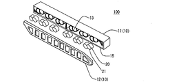
- FIG. 1 is an exploded perspective view schematically showing an exploded embodiment of a pressure regulating valve of the present invention;
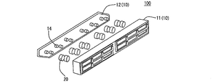
- FIG. 1 is an exploded perspective view schematically showing an exploded embodiment of a pressure regulating valve of the present invention;
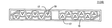
- FIG. 1 is a plan view schematically showing a housing body in one embodiment of a pressure regulating valve of the present invention;
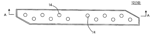
- FIG. FIG. 4 is a plan view schematically showing a lid body in one embodiment of the pressure regulating valve of the present invention;
- FIG. 6 is a cross-sectional view schematically showing an AA cross section of the lid shown in FIG.
- FIG. 5; 1 is a cross-sectional view schematically showing a cross-section cut in a thickness direction of one embodiment of a pressure regulating valve of the present invention
- FIG. FIG. 4 is a plan view schematically showing the bottom of the concave portion of the housing body in one embodiment of the pressure regulating valve of the present invention
- FIG. 10 is a plan view schematically showing the bottom of the concave portion of the housing body in another embodiment of the pressure regulating valve of the present invention
- FIG. 10 is a plan view schematically showing the bottom of the concave portion of the housing body in still another embodiment of the pressure regulating valve of the present invention
- FIG. 8 is a cross-sectional view schematically showing a cross section corresponding to the cross section shown in FIG.
- FIG. 10 is a plan view schematically showing the bottom of the concave portion of the housing body in still another embodiment of the pressure regulating valve of the present invention
- FIG. 10 is a plan view schematically showing the bottom of the concave portion of the housing body in still another embodiment of the pressure regulating valve of the present invention
- FIG. 4 is an explanatory view schematically showing a partially see-through positional relationship among a valve body, a protrusion, and a pressure introducing passage in one embodiment of the pressure regulating valve of the present invention.
- FIG. 3 is an explanatory view schematically showing a usage state in one embodiment of the pressure regulating valve of the present invention;
- FIG. 3 is an explanatory view schematically showing a usage state in one embodiment of the pressure regulating valve of the present invention
- FIG. 10 is a plan view schematically showing the bottom of the concave portion of the housing body in still another embodiment of the pressure regulating valve of the present invention
- FIG. 18 is a cross-sectional view schematically showing a BB cross section in the housing body shown in FIG. 17
- FIG. 18 is an explanatory view schematically showing a partially see-through positional relationship among a valve body, a protrusion, and a pressure introducing passage in the pressure regulating valve shown in FIG. 17
- FIG. 8 is a cross-sectional view schematically showing a cross section corresponding to the cross section shown in FIG.
- FIG. 21 is a perspective view schematically showing a valve body that constitutes the pressure regulating valve shown in FIG. 20;
- FIG. 8 is a cross-sectional view schematically showing a cross section corresponding to the cross section shown in FIG. 7 in another embodiment of the pressure regulating valve of the second invention;
- 8 is a cross-sectional view schematically showing a cross section corresponding to the cross section shown in FIG. 7 in still another embodiment of the pressure regulating valve of the second invention;
- FIG. FIG. 24 is a perspective view schematically showing a valve body that constitutes the pressure regulating valve shown in FIG. 23;
- FIG. 1 shows a power storage module 200 in which two pressure regulating valves 100 are horizontally arranged side by side and connected.
- the power storage module 200 has a plurality of cells 60 each having a positive electrode, a bipolar electrode having a current collector and a negative electrode, and a separator, and the plurality of cells 60 are vertically stacked.
- the power storage modules 200 are arranged in a state in which a plurality of layers are stacked in the vertical direction.
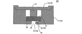
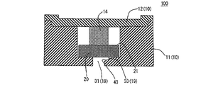
- the pressure regulating valve 100 includes a housing body 11 having an opening 15 and a recess 13 formed therein, and a lid 12 closing the opening 15 of the housing body 11. and a columnar valve element 20 that is an elastic member that is housed in a recess 13 of a housing body 11 of the housing 10 .
- the housing body 11 has a pressure introduction path 19 formed of a through hole through which pressure from the power storage module 200 (see FIG. 1) is introduced in the bottom 17 of the recess 13.
- FIG. 1 As shown in FIG.
- the pressure introduction path 19 has a pressure introduction portion 31 which is a columnar space penetrating the housing body 11 and a groove portion 33 which is connected to the pressure introduction portion 31 and opens to the surface of the bottom portion 17 . is doing.
- the valve body 20 is arranged so as to cover the opening 35 of the pressure introducing passage 19 on the side of the bottom portion 17, as shown in FIG.
- the lid body 12 has a protrusion 14 that contacts the end surface of the valve body 20, as shown in FIGS.
- the opening 15 of the housing body 11 is closed with the lid 12, so that the protrusion 14 of the lid 12 pressurizes the valve body 20, and the valve body 20 opens the pressure introduction passage 19.
- a pressure regulating valve for power storage modules that seals airtightly. 6 is a schematic cross-sectional view of the AA cross section of the lid shown in FIG.
- Such a pressure regulating valve 100 can be operated (that is, the valve is opened) at a desired pressure with high accuracy, and can be manufactured with a small number of man-hours.
- the pressure regulating valve 100 receives pressure, it is determined whether or not to open depending on the magnitude of the pressure. Here, it is important to control how much pressure is received to open the valve. It is more important to precisely adjust the valve opening pressure, and the conventional pressure regulating valve as disclosed in Patent Document 2 has room for further improvement.
- the function as a regulating valve largely depends on the elastic characteristics of the elastic member (that is, the spring element). Highly affected by variability. Furthermore, the function of the conventional pressure regulating valve as a regulating valve is susceptible to settling and aging of the elastic member. In other words, the pressure control valve is desired to open when the desired pressure is applied as described above. tends not to be easy.
- the structure of the pressure regulating valve of the present invention it is possible to suppress variations in the pressure for opening the valve due to the valve element 20 being an elastic member, and furthermore, the groove 33 is provided. Therefore, the valve can be opened more accurately according to the received pressure. Furthermore, by using an elastic member that satisfies a desired size, batch production becomes possible, and the number of man-hours can be reduced. As a result, it can be manufactured at low cost.
- the housing 10 includes a housing body 11 having an opening 15 and a recess 13 formed therein, and a lid 12 closing the opening 15 of the housing body 11. It is.
- a housing 10 is connected to the power storage module 200 (see FIG. 1) and communicates with the inside of the power storage module 200 via the pressure introducing path 19 which is a through hole formed in the bottom portion 17 of the recess 13. Become.
- the shape of the housing 10 is not particularly limited, and may be a substantially quadrangular prism shape or the like.
- the size of the housing 10 is not particularly limited, and can be appropriately set in relation to the size of the power storage module.
- Case body The housing body 11 is box-shaped with an opening 15, and a recess 13 is formed inside thereof.
- the bottom portion 17 of the concave portion 13 has a pressure introduction passage 19 formed of a through hole through which pressure from the power storage module 200 is introduced.
- the housing body 11 may be, for example, a hollow polygonal prism having an opening 15 without one of its side walls.
- the material of the housing body 11 is not particularly limited, but synthetic resin can be used, for example.
- the shape of the housing body 11 is not particularly limited, but may be, for example, a quadrangular prism shape, a hexagonal prism shape, or the like.
- FIG. 7 shows a cross section of one embodiment of the pressure control valve of the present invention cut in the thickness direction (that is, a substantially quadrangular prism-shaped pressure control valve in the central axis direction (the axial direction in which the valve body 20 is arranged).
- FIG. 2 is a cross-sectional view schematically showing a cross section cut by an orthogonal plane).
- the shape of the concave portion 13 is not particularly limited, and may be, for example, a substantially cylindrical shape as long as the valve body 20 can be accommodated appropriately.
- a convex portion 16 may protrude from the inner wall surface of the concave portion 13 (see FIG. 8). By forming the convex portion 16 in this way, a gap is formed between the concave portion 13 and the valve body, and when the valve body 20 is opened, the pressure from the power storage module 200 is released through this gap. (that is, this gap becomes a flow path for the gas discharged from the power storage module 200).
- the size of the recess 13 is not particularly limited, and when the recess 13 is a substantially cylindrical space, the maximum outer diameter and the axial length of the opening (length in the depth direction of the housing body 11) are It can be set as appropriate.
- One recess 13 may be provided in one housing body 11, or a plurality of recesses 13 may be provided as shown in FIG.
- a plurality of recesses 13 that is, by using a plurality of valve bodies 20 housed in each recess 13
- pressure can be quickly reduced.
- the pressure introduction path 19 includes a pressure introduction portion 31 which is a columnar space penetrating the housing body 11 and a space connected to the pressure introduction portion 31 and opening to the surface of the bottom portion 17 . and a certain groove portion 33 .
- Pressure regulating valve 100 communicates with power storage module 200 via pressure introduction path 19, and when pressure in power storage module 200 rises, pressure regulating valve 100 also receives the same pressure. Then, when the predetermined pressure is exceeded, the pressure regulating valve 100 is opened, and the pressure inside the power storage module 200 can be reduced.
- the pressure introduction part 31 is a through hole that communicates with the power storage module 200 (see FIG. 7). That is, the pressure introduction part 31 opens to the surface side of the housing body 11 and also opens to the bottom part 17 side of the recess 13 .
- the outer diameter of the pressure introducing portion 31 is not particularly limited, and may be the same as the pressure introducing portion formed in a conventionally known pressure regulating valve for an electricity storage module.
- the pressure introduction part 31 is usually a columnar space, but there is no particular limitation on this shape, and it may be an elliptical columnar space or a polygonal (polygonal) space.
- the groove portion 33 is a space connected to the pressure introduction portion 31 and opened to the surface of the bottom portion 17 (see FIGS. 7 and 8).
- the opening area of the pressure introducing passage 19 on the bottom portion 17 side can be made larger than the opening area of the pressure introducing portion 31 on the bottom portion 17 side.
- the opening area of the pressure introduction passage 19 is increased by the amount of the groove 33, compared to the case where only the pressure introduction portion 31 is formed.
- whether or not to open the valve is determined by the magnitude per unit area of the pressure that the valve body 20 receives. It is possible to precisely control the timing to be performed. In other words, it is possible to achieve a desired operating pressure in the pressure regulating valve, and to obtain a pressure regulating valve that opens precisely when receiving a specific pressure.
- the opening area of the groove portion 33 can be appropriately set according to the state of the power storage module 200, etc., as described above.
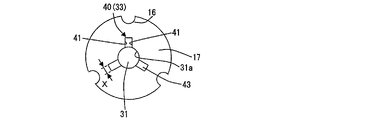
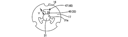
- the shape of the groove portion 33 is not particularly limited, it preferably has a shape having a radial groove portion 40 extending outward from a portion of the pressure introduction portion 31 as shown in FIG.
- the valve can be opened more accurately. That is, when the groove portion 33 extends outward from the entire pressure introducing portion 31 (when the groove portion 33 is formed along the entire circumference of the pressure introducing portion 31), the valve body 20, which is an elastic member, bends and the groove portion There is also a concern that the fluid may excessively enter 33 and block the pressure introducing portion 31 . In order to avoid this, it is conceivable to deepen the groove portion 33, but in this case, the state of the valve body 20 tends to be destabilized.
- the valve body 20 can be clearly crushed and the groove portion 33 can be partially compressed. Since the pressure can be effectively introduced, the above concern can be eliminated.
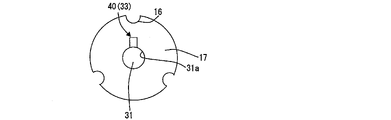
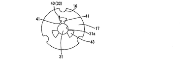
- the radial groove portion 40 may be formed at one location as shown in FIG. 9, or may be formed at a plurality of locations as shown in FIGS.
- the positional relationship between the radial grooves 40 is not particularly limited, but they can be arranged at equal intervals in the circumferential direction of the pressure introducing portion 31 . By doing so, the pressure applied to the valve body 20 becomes uniform, and the valve body 20 can be opened more accurately at a desired timing.
- the number is not particularly limited, but may be, for example, about 2 to 6.
- the radial groove portion 40 extends outward from a part of the pressure introduction portion 31, there is no particular limitation on the extending direction or the shape of the opening. shape), fan shape, semicircular shape, semielliptical shape, and the like.
- the shape of the opening of the radial groove portion 40 refers to the shape of the closed space of the radial groove portion 40 drawn in plan views of the bottom portion 17 of the recess 13 viewed from above, as shown in FIGS. 8 to 10, for example.
- FIG. 8 and 9 show an example in which the shape of the opening of the radial groove portion 40 is square
- FIG. 10 shows an example in which the shape of the opening of the radial groove portion 40 is fan-shaped.
- valve body 20 when the inside of the electricity storage module 200 becomes hot and the valve body 20 is exposed to the high temperature, the valve body 20 tends to soften and bite into the groove portion 33 . If the valve body 20 is cooled in this state, the valve body 20 tends to remain in the groove 33 . In this case, when pressure is applied to the valve element 20 again, the pressure necessary for opening the valve tends to increase due to the groove 33 being bitten. Moreover, the valve body 20 tends to be excessively bitten not only after cooling but also at high temperatures. Therefore, there is a concern that the valve cannot be opened accurately at a desired pressure.
- the shape of the opening is the fan-shaped radial groove portion 40
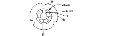
- the valve can be opened more accurately not only after cooling but also at high temperatures. It should be noted that this advantage is not limited to the case where the shape of the opening is fan-shaped or the like, but when the bottom surface 43 is an inclined surface as shown in FIG. In the case of the shape (T-shape), as shown in FIG. 13, it is exhibited also in the case of having an annular groove portion 49 (communication groove).
- the radial groove portion 40 is preferably formed as follows. That is, if the pressure introducing portion 31 has a circular shape in a cross section perpendicular to the direction in which the pressure introducing portion 31 extends, the pair of side walls 41 of the radial groove portion 40 are parallel to the radial direction of the pressure introducing portion 31 . Alternatively, it is preferably formed obliquely to the radial direction of the pressure introducing portion 31 instead of being parallel to the radial direction of the pressure introducing portion 31 . If the pair of side walls 41 are parallel to the radial direction of the pressure introducing portion 31 (if the opening shape is rectangular), management is easy because there are only two characteristics of length and width.
- the pressure receiving area (projection It is possible to increase the pressure-receiving area on the outer peripheral side of the central portion while suppressing the area).
- FIG. 8 shows a case where the shape of the pressure introducing portion 31 is circular in the cross section perpendicular to the direction in which the pressure introducing portion 31 extends, and the pair of side walls 41 of each radial groove portion 40 are aligned with the pressure introducing portion 31.
- An example of parallel to the radial direction is shown.
- FIG. 10 shows a case where the shape of the pressure introducing portion 31 is circular in a cross section perpendicular to the direction in which the pressure introducing portion 31 extends. shows an example formed obliquely with respect to the radial direction of the pressure introduction portion 31 instead of being parallel to the pressure introduction portion 31 .
- FIG. 10 shows a mode in which the pair of side walls 41 of each radial groove 40 are spaced apart from each other as they extend outward, they may be spaced apart as they extend outward.
- the distance (minimum distance) X between the pair of side walls 41 of the radial groove 40 is not particularly limited and can be set as appropriate. If the distance X is appropriately set, the valve body 20 becomes more difficult to bite into the radial groove portion 40, and the valve can be opened more accurately.
- the bottom surface 43 of the radial groove portion 40 may be a plane that is parallel to the surface of the bottom portion 17 of the recess 13 , or the depth of the radial groove portion 40 gradually decreases outward from the pressure introducing portion 31 . It may be an inclined surface.
- the bottom surface 43 is the inclined surface as described above, for example, when the area of the radial groove portion 40 is large such that the opening shape is fan-shaped, the radial groove portion 40 is to the extent that the valve body, which is an elastic member, bites into the radial groove portion 40 (biting). amount) tends to increase, and the amount of physical bite can be suppressed.
- FIG. 7 shows an example in which the bottom surface 43 of the radial groove portion 40 is a plane parallel to the surface of the bottom portion 17 of the recess portion 13 .
- 11 shows an example in which the bottom surface 43 of the radial groove portion 40 is an inclined surface, and the depth of the radial groove portion 40 gradually decreases outward from the pressure introducing portion 31 on this inclined surface. is shown.
- the groove portion 33 can further have a cross-direction groove portion 45 that intersects with the radial groove portion 40 in addition to the radial groove portion 40 .
- the intersecting direction groove portion 45 is part of a concentric circle with the wall surface 31a constituting the pressure introducing portion 31. It can have an arcuate groove 47 formed along an arc. It should be noted that the grooves are not limited to the arcuate grooves 47 and may be grooves with polygonal openings.
- the valve body 20 With the intersecting direction groove portion 45 (especially the arcuate groove portion 47), the valve body 20 becomes more difficult to bite into the radial direction groove portion 40, and the valve can be opened more accurately. That is, although the radial groove portion 40 is difficult for the valve body 20 to bite into, for example, the pair of side walls 41 of the radial groove portion 40 are aligned with the pressure introducing portion 31 in the radial direction, such as when the opening shape is square. In the case of being parallel, there is a tendency that the radial groove 40 tends to bite into on the free end side (that is, the pressure introducing portion side).
- the arcuate groove 47 preferably has an arc angle (central angle) of 30 to 60°. With such a range, it is possible to further suppress the occurrence of biting of the valve body 20 on the free end side of the radial groove portion 40 .
- the "arc" refers to the arc drawn by each of the pair of side walls. In other words, each of the arcs drawn by the pair of partition walls preferably satisfies the range of the central angle.
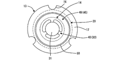
- the cross-direction groove part 45 may have an annular groove part 49, which is an annular groove, as shown in FIG.
- FIG. 13 shows an example in which the radial grooves 40 communicate with each other through the annular groove 49, all the radial grooves 40 may not communicate with each other.
- the valve can be opened more accurately. That is, as described above, there is a concern that the pressure required for opening the valve may increase due to the valve body 20 still being bitten into the groove 33. The valve can be opened accurately with pressure.
- the distance Y between the pair of side walls 41 of the cross-direction groove 45 is not particularly limited, and may be the same as the distance X between the pair of side walls 41 of the radial groove 40, for example.
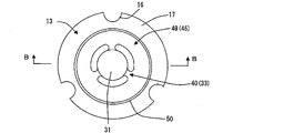
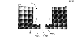
- a bead portion 50 may be provided on the bottom portion 17 of the concave portion 13 as shown in FIGS. 17 and 18 .
- the cross-direction groove portion 45 may be annular, and an annular bead portion 50 may be formed on the outer side of the cross-direction groove portion 45 .
- the valve body 20 and the bottom portion 17 of the recess 13 tend to adhere to each other, increasing the valve opening pressure.
- Factors for such sticking include compatibility between materials (surface energy, etc.), temperature environment, contact area, and the like. Focusing on the contact area of these, the bead portion 50 can be provided.
- the bead portion 50 it is preferable to increase the area occupied by the groove portion 33 with respect to the area of the bottom portion 17 in order to reduce the contact area.
- the bead portion 50 has an annular shape, and more specifically, has a continuous ring shape without any discontinuous portion.
- the shape of the bead portion 50 (the shape when viewed from above as shown in FIG. 17) is not particularly limited as long as it is annular, and can be an annular ring, an elliptical ring, a polygonal ring, or the like.
- the height of the bead portion 50 is not particularly limited and can be set as appropriate, and the height can be the same at any position of the bead portion 50 . Also, the height of the bead portion 50 can be higher than other portions of the bottom portion 17, as shown in FIG.
- the area occupied by the groove portion 33 with respect to the area of the bottom portion 17 can be appropriately set depending on the material and the environmental temperature.
- the shape of the bead portion 50 in the cross section along the height direction is not particularly limited, and may be, for example, rectangular, trapezoidal, or semicircular.
- the formation position of the bead portion 50 is not particularly limited as long as it is outside the intersecting direction groove portion 45, and can be determined as appropriate. That is, when the bead portion 50 and the projecting portion 14 are viewed from the central axis direction of the projecting portion 14 (see FIG. 19), the projecting portion 14 is entirely positioned within the region inside the annular bead portion 50. is good. By doing so, an increase in the valve opening pressure can be suppressed more reliably.
- the bead portion 50 is formed on the outer edge portion of the intersecting direction groove portion 45, and when formed at such a position, it is possible to suppress a decrease in valve opening pressure.
- the contact area of the valve body made of rubber must be minimized, but in that case, the pressure receiving area increases and the valve opening pressure tends to decrease. Therefore, by providing the bead portion on the outer edge portion, the deflection amount of the rubber valve body can be increased, and as a result, a decrease in the valve opening pressure can be suppressed.
- the lid 12 closes the opening 15 of the housing body 11 and has a projection 14 that contacts the end surface 21 of the valve body 20 (see FIGS. 5 and 6).
- the lid 12 is fixed to the housing body 11 by a method such as welding with the opening 15 of the housing body 11 .
- a pressure discharge hole is formed in the lid 12, and when the pressure inside the pressure regulating valve 100 rises, the gas inside the pressure regulating valve 100 is discharged through the pressure regulating valve 100. pressure drops.
- the material of the lid body 12 is not particularly limited, and the same material as the material of the housing body 11 can be appropriately adopted, and examples thereof include synthetic resin.
- the shape and dimensions of the projection 14 are not particularly limited as long as the valve body 20 can be pressurized by closing the opening 15 of the housing body 11 with the lid 12. It can be columnar, polygonal columnar, or the like.
- the top surface of the protrusion 14 that contacts the valve body 20 is preferably of a size that does not cover the entire opening of the pressure introduction passage 19 on the bottom 17 side of the recess 13 . That is, as shown in FIG. 14, the positional relationship between the outer edge A of the top surface of the protrusion 14 and the outer edge B of the opening of the recess 13 on the side of the bottom 17 in the pressure introducing passage 19 is determined from the axial direction of the protrusion 14. As can be seen, at least a portion of the outer edge B should be located outside the outer edge A. That is, it is preferable that the outer edge B protrudes from the outer edge A.
- the height of the protrusion 14 can be appropriately set based on the relationship with the thickness of the valve body 20 and the like. By adjusting the height of the protrusion 14, the valve body 20 can be favorably pressurized when the opening 15 of the housing body 11 is closed with the lid body 12. can be hermetically sealed.
- valve body 20 is a columnar elastic member that is housed in the recess 13 of the housing body 11 of the housing 10 .
- the valve body 20 is arranged so as to cover the opening of the pressure introduction passage 19 on the bottom 17 side of the recess 13 .
- the valve body 20 has a shorter axial length than its outer diameter.
- valve body 20 When the pressure in power storage module 200 rises to a desired value, valve body 20 separates from bottom 17 of recess 13 to create a gap between valve body 20 and bottom 17 of recess 13 . , the compressed gas in the power storage module 200 is introduced from the power storage module 200 into the pressure regulating valve 100 through this gap, and the pressure in the power storage module 200 is reduced. After the pressure in the power storage module 200 is reduced, the valve body 20 returns to its original position due to the elastic force of the valve body 20 and comes into contact with the bottom portion 17 of the recess 13 to airtightly block the pressure introduction passage 19 .
- the material of the valve body is not particularly limited as long as it is an elastic member, and examples include rubber.
- the valve body 20 has a shorter axial length than its outer diameter. By doing so, it is possible to avoid variations in the valve opening pressure due to the axial length of the valve body 20 as in the conventional pressure regulating valve disclosed in Patent Document 2.
- the valve body of the conventional pressure regulating valve is longer than the depth of the recess for accommodating the valve body. and airtightly closes the pressure introduction path 19 .
- the longer the valve body is the more the elastic force varies depending on the manufacturing accuracy. Therefore, there is a tendency that the valve does not open even though the power storage module 200 receives a desired pressure to open the valve. Therefore, as in the present invention, by making the outer diameter of the valve body smaller than the length in the axial direction, it is possible to suppress variations in the valve opening operation due to the length of the valve body. .
- the valve body 20 has a columnar shape. As described above, the length in the axial direction is shorter than the outer diameter. " can also be referred to as plate-like or board-like. More specifically, the valve body 20 can be substantially disc-shaped or the like.
- the pressure regulating valve 100 which is one embodiment of the pressure regulating valve of the present invention, can be used, for example, as follows. First, the pressure regulating valve 100 is connected and fixed to the power storage module 200 (see FIG. 1), and the inside of the pressure regulating valve 100 and the power storage module 200 are communicated through the pressure introducing path 19 .
- the power storage module 200 When the power storage module 200 is used, for example, in a nickel-metal hydride battery, hydrogen may be generated due to overdischarge or the like within the battery, which may increase the pressure inside the battery.
- the pressure in pressure regulating valve 100 pressure introduction passage 19
- the pressure in the pressure regulating valve 100 exceeds a predetermined pressure
- the pressure causes the valve to open. That is, as shown in FIG. 16 , the valve body 20 of the pressure regulating valve 100 is separated from the bottom portion 17 of the recess 13 to create a gap between the valve body 20 and the bottom portion 17 of the recess 13 .
- Compressed gas (indicated by a black arrow) in power storage module 200 is introduced into pressure regulating valve 100 through this gap.
- Compressed gas introduced into the pressure regulating valve 100 passes through the recess 13 and is discharged from the discharge hole of the lid 12 .
- the timing of starting the valve opening operation of the valve body 20 is determined by the magnitude of the pressure that the valve body 20 receives from the compressed gas in the power storage module 200 . That is, it is designed to open the valve when the pressure per unit area received by the valve body 20 reaches a predetermined value or higher.
- the magnitude of the pressure per unit area that the valve body 20 receives is adjusted. At this time, by setting the valve body 20 to a predetermined size, the influence of variations in elastic force due to errors in manufacturing the valve body 20 made of an elastic material is reduced.
- valve body 20 By setting the valve body 20 to a predetermined size, the cost per unit of the valve body 20 can be reduced, and the replacement cost can be reduced.
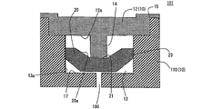
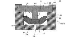
- the pressure regulating valve 101 includes a housing 10 having a housing body 110 having an opening 15 and a recess 13 formed therein, and a lid body 12 closing the opening 15 of the housing body 110; and a disc-shaped valve element 20 that is an elastic member that is housed in the concave portion 13 of the housing body 110 in the above. Further, the housing body 110 has, in the bottom portion 17 of the concave portion 13, a pressure introduction path 190 formed of a through hole through which pressure from the power storage module is introduced. The length in the thickness direction of the valve body 20 is shorter than the depth of the recess 13 and the thickness is smaller than the outer diameter. It has a lip 23 which abuts to form a sealed structure. In this pressure regulating valve 101, the valve body 20 makes the inside of the recess 13 airtight, and is for an electric storage module.
- the “depth of the recess” means the height of the inner wall surface (length of the recess in the axial direction) in the recess having the inner wall surface and the bottom. Therefore, for example, when the bottom of the recess is tapered, the "depth of the recess" is the boundary between the inner wall surface and the bottom.
- Such a pressure regulating valve 101 can be operated accurately at a desired pressure (that is, operate to reduce the pressure in the power storage module), and can be manufactured with a small number of man-hours.
- the pressure regulating valve 101 receives pressure, it is determined whether or not it operates depending on the magnitude of the pressure. Here, it is important to control how much pressure is applied to operate. Accurately adjusting the operating pressure is more important, and there is room for further improvement in the conventional pressure regulating valve as described in Patent Document 2.
- the function as a regulating valve largely depends on the elastic characteristics of the elastic member (that is, the spring element). Highly affected by variability. Furthermore, the function of the conventional pressure regulating valve as a regulating valve is susceptible to settling and aging of the elastic member. In other words, the pressure control valve is desired to operate when the desired pressure is applied as described above. tend not to.
- rubber with a lip is known as a pressure regulating valve (for example, JP-A-2020-102541, JP-A-2006-156868).
- a pressure regulating valve for example, JP-A-2020-102541, JP-A-2006-156868.
- JP-A-2020-102541 Japanese Patent Application Laid-Open No. 2020-102541
- the characteristics may change due to the angle of the mating surface (valve seat) with which the lip portion contacts, the eccentricity of the rubber valve body, and the like.
- Japanese Patent Application Laid-Open No. 2006-156868 there is a concern that the contact state of the lip portion (seal lip) may become unstable due to the influence of dimensional variations in the positioning rubber.
- the configuration of the pressure regulating valve of the present invention it is possible to suppress variations in pressure for operation due to the fact that the valve element 20 is an elastic member. can work well. Furthermore, by using an elastic member that satisfies a desired size, batch production becomes possible, and the number of man-hours can be reduced. As a result, it can be manufactured at low cost. Also, as described above, in JP-A-2020-102541, while there is the above concern, in the present invention, the surface that the valve body contacts is only the outer periphery, and the valve body that is an elastic member alone has a function of aligning. Therefore, stabilization of the valve opening pressure can be expected. Further, while JP-A-2006-156868 has the above concern, the present invention does not require compression for the purpose of positioning, so the above concern can be alleviated.
- the housing 10 includes a housing body 110 having an opening 15 and a recess 13 formed therein, and a lid 12 closing the opening 15 of the housing body 110. .
- a housing 10 is connected to the power storage module 200 (see FIG. 1) and communicates with the inside of the power storage module 200 via the pressure introducing path 190 which is a through hole formed in the bottom portion 17 of the recess 13. Become.
- the shape of the housing 10 is not particularly limited, and can be a substantially quadrangular prism like the pressure regulating valve 100 described above.
- the size of the housing 10 is not particularly limited, and can be appropriately set in relation to the size of the power storage module.
- housing body 110 As shown in FIG. 20, the housing body 110 has a box-like shape with an opening 15 and a recess 13 formed inside. The bottom portion 17 of the concave portion 13 has a pressure introduction passage 190 formed of a through hole through which pressure from the power storage module 200 is introduced.
- the housing body 110 may be, for example, a hollow polygonal prism with one side wall missing to form the opening 15 .
- the material of the housing body 110 is not particularly limited, but synthetic resin can be used, for example.
- the shape of the housing body 110 is not particularly limited, but it can be, for example, a quadrangular prism shape, a hexagonal prism shape, or the like.
- the recess 13 is a bottomed hole extending in the depth direction of the box-shaped housing body 110 . It has a pressure introduction path 190 that is A disc-shaped valve body 20 that is an elastic member is housed in the recess 13 , and can be said to be a space for housing the valve body 20 .
- the shape of the concave portion 13 is not particularly limited, and may be, for example, a substantially cylindrical shape as long as the valve body 20 can be accommodated appropriately.
- the size of the recess 13 is not particularly limited, and when the recess 13 is a substantially cylindrical space, the maximum outer diameter and the axial length of the opening (length in the depth direction of the housing body 110) are It can be set as appropriate.
- One recess 13 may be provided in one housing body 110, or a plurality of recesses may be provided.
- a plurality of recesses 13 that is, by using a plurality of valve bodies 20 housed in each recess 13
- pressure can be quickly reduced.
- Pressure introduction path As shown in FIG. 20, the pressure introduction path 190 is a through hole formed in the bottom portion 17 of the recess 13 and through which pressure from the power storage module is introduced. Pressure regulating valve 101 communicates with power storage module 200 via pressure introduction path 190, and when pressure in power storage module 200 rises, pressure regulating valve 101 also receives the same pressure. Then, when the pressure exceeds a predetermined value, the pressure regulating valve 101 operates to reduce the pressure in the power storage module 200 .
- the lid 12 closes the opening 15 of the housing body 110 (see FIG. 20).
- the lid 12 is fixed to the housing body 110 by a method such as welding with the opening 15 of the housing body 110 .
- a pressure discharge hole is formed in the lid body 12, and when the pressure inside the pressure regulating valve 101 rises, the gas inside the pressure regulating valve 101 is discharged through this pressure discharging hole. pressure drops.
- the material of the lid body 12 is not particularly limited, and the same material as the material of the housing body 11 can be appropriately adopted, and examples thereof include synthetic resin.
- the lid body 12 may have a protrusion 14 that contacts the end surface 21 of the valve body 20 .
- the recess and the protrusion 14 can be engaged to allow the valve body 20 to have a positioning function.
- a portion of the protrusion 14 that contacts the valve body 20 does not correspond to the rear surface 12 a of the lid body 12 .
- the shape and dimensions of the protrusion 14 are not particularly limited, and may be cylindrical, elliptical, or polygonal, for example.
- the height of the protrusion 14 can be appropriately set based on the relationship with the thickness of the valve body 20 and the like. By doing so, it is possible to satisfactorily prevent the position of the valve body 20 from being displaced when the opening 15 of the housing body 110 is closed with the lid body 12 .
- valve body 20 is a board-like elastic member that is accommodated in the recess 13 of the housing body 110 of the housing 10 .
- the length in the thickness direction of the valve body 20 is shorter than the depth of the recess 13, and the thickness is smaller than the outer diameter.
- the lip portion 23 of the valve body 20 deforms, creating a gap between the lip portion 23 and the inner wall surface 13a of the recess 13. Confidentiality is broken. Thereby, the pressure in the power storage module 200 is lowered.
- the protrusion 14 is provided on the lid body 12
- the elastic force of the valve body 20 causes the valve body 20 to return to its original position after the pressure in the power storage module 200 is lowered.
- the depth of the concave portion 13 is the width of the side surface of the concave portion 13 (length in the axial direction).
- the length in the thickness direction of the valve body 20 is shorter than the depth of the recess 13.
- valve body 20 it is possible to avoid variations in the operating pressure due to the axial length of the valve body 20 as in the conventional pressure regulating valve shown in Patent Document 2. be able to.
- the valve body of the conventional pressure regulating valve is longer than the depth of the recess for accommodating the valve body. and airtightly closes the pressure introduction path 190 .
- the longer the valve body is the more the elastic force varies depending on the manufacturing accuracy. Therefore, there is a tendency that the power storage module 200 does not operate even though it receives a desired pressure to operate. Therefore, as in the present invention, by making the thickness of the valve body smaller than its outer diameter, it is possible to suppress the variation in the operation start timing due to the length of the valve body.
- the material of the valve body is not particularly limited as long as it is an elastic member, and examples include rubber.
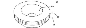
- the valve body 20 has a columnar shape, but as described above, the length in the thickness direction is smaller than the outer diameter. can. More specifically, the valve body 20 can be substantially disc-shaped or the like.
- valve body 20 Since the length in the thickness direction of the valve body 20 is shorter than the depth of the recess 13, the valve body 20 can be arranged apart from the rear surface 12a of the lid body 12 as shown in FIG. In the case where the lid 12 is spaced apart from the back surface 12a of the lid 12 in this way, it is not in contact with the lid 12, so there is no need to provide a groove in the mating part (the lid 12), thereby simplifying the structure. can be done. Moreover, since the vertical restraint can be minimized, the operation of the valve body 20 is not hindered.
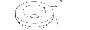
- the lip portion 23 is in contact with the inner wall surface 13a of the concave portion 13 of the housing body 110 to form a sealing structure.
- a lip portion 23 can appropriately adopt a structure similar to a lip portion used in a conventionally known sealing structure.
- FIG. 23 is a cross-sectional view schematically showing a cross section corresponding to the cross section shown in FIG. 7 in still another embodiment of the pressure regulating valve of the second invention.
- 24 is a perspective view schematically showing the valve body 20 constituting the pressure regulating valve 101 shown in FIG. 23. As shown in FIG. 23
- the pressure regulating valve 101 which is one embodiment of the pressure regulating valve of the second invention, can be used, for example, as follows. First, the pressure regulating valve 101 is connected and fixed to the power storage module 200 , and the inside of the pressure regulating valve 101 and the inside of the power storage module 200 are communicated through the pressure introducing path 190 .
- the power storage module 200 When the power storage module 200 is used, for example, in a nickel-metal hydride battery, hydrogen may be generated due to overdischarge or the like within the battery, which may increase the pressure inside the battery. In this case, the pressure inside the pressure regulating valve 101 (pressure introduction passage 190) also rises. Then, when the pressure in the pressure regulating valve 101 (the pressure introduction passage 190) exceeds a predetermined pressure, pressure reduction operation is performed by this pressure. That is, a gap is formed between the lip portion 23 of the valve body 20 and the side surface of the recess 13 . Accordingly, it is possible to avoid a situation in which the compressed gas in the electricity storage module 200 is introduced outside the pressure regulating valve 101, the pressure in the electricity storage module 200 is lowered, and the electricity storage module 200 is damaged.
- the start timing of the pressure reducing operation of the valve body 20 is determined by the magnitude of the pressure that the valve body 20 receives from the compressed gas in the power storage module 200 . That is, when the pressure per unit area received by the valve body 20 reaches a predetermined value or higher, the pressure reduction operation is performed.
- the valve body 20 has a predetermined dimension (the length in the thickness direction is shortened and the dimension is set apart from the lid body 12). By reducing the influence of variations in elastic force, the timing of starting the decompression operation is controlled more accurately.
- valve body 20 By setting the valve body 20 to a predetermined size, the cost per unit of the valve body 20 can be reduced, and the replacement cost can be reduced.
- the pressure regulating valve of the present invention can be used as a pressure regulating valve used in power storage modules used in vehicles and the like.
Landscapes
- Chemical & Material Sciences (AREA)
- Chemical Kinetics & Catalysis (AREA)
- Electrochemistry (AREA)
- General Chemical & Material Sciences (AREA)
- Gas Exhaust Devices For Batteries (AREA)
- Control Of Fluid Pressure (AREA)
Priority Applications (5)
| Application Number | Priority Date | Filing Date | Title |
|---|---|---|---|
| US18/284,672 US20240274965A1 (en) | 2021-04-28 | 2022-01-06 | Pressure regulating valve |
| EP22795167.0A EP4333167B1 (en) | 2021-04-28 | 2022-01-06 | Pressure regulation valve |
| KR1020237033378A KR102958945B1 (ko) | 2021-04-28 | 2022-01-06 | 압력 조정 밸브 |
| JP2023517038A JP7407335B2 (ja) | 2021-04-28 | 2022-01-06 | 圧力調整弁 |
| CN202280025574.7A CN117099252A (zh) | 2021-04-28 | 2022-01-06 | 压力调节阀 |
Applications Claiming Priority (2)
| Application Number | Priority Date | Filing Date | Title |
|---|---|---|---|
| JP2021075908 | 2021-04-28 | ||
| JP2021-075908 | 2021-04-28 |
Publications (1)
| Publication Number | Publication Date |
|---|---|
| WO2022230244A1 true WO2022230244A1 (ja) | 2022-11-03 |
Family
ID=83846840
Family Applications (1)
| Application Number | Title | Priority Date | Filing Date |
|---|---|---|---|
| PCT/JP2022/000254 Ceased WO2022230244A1 (ja) | 2021-04-28 | 2022-01-06 | 圧力調整弁 |
Country Status (6)
| Country | Link |
|---|---|
| US (1) | US20240274965A1 (cg-RX-API-DMAC7.html) |
| EP (1) | EP4333167B1 (cg-RX-API-DMAC7.html) |
| JP (1) | JP7407335B2 (cg-RX-API-DMAC7.html) |
| KR (1) | KR102958945B1 (cg-RX-API-DMAC7.html) |
| CN (1) | CN117099252A (cg-RX-API-DMAC7.html) |
| WO (1) | WO2022230244A1 (cg-RX-API-DMAC7.html) |
Cited By (1)
| Publication number | Priority date | Publication date | Assignee | Title |
|---|---|---|---|---|
| JP2024500680A (ja) * | 2021-08-19 | 2024-01-10 | エルジー エナジー ソリューション リミテッド | 二次電池およびこれを含むデバイス |
Citations (7)
| Publication number | Priority date | Publication date | Assignee | Title |
|---|---|---|---|---|
| US6645661B2 (en) * | 2000-04-20 | 2003-11-11 | Agouron Pharma | Seal and bleed valve unit for electric batteries |
| JP2006156868A (ja) | 2004-12-01 | 2006-06-15 | Nok Corp | 圧力開放弁 |
| JP2010287451A (ja) | 2009-06-12 | 2010-12-24 | Nissan Motor Co Ltd | 薄型電池及びその製造方法 |
| JP2013062120A (ja) * | 2011-09-13 | 2013-04-04 | Toyota Motor Corp | 安全弁を備えた電池 |
| WO2019064843A1 (ja) | 2017-09-26 | 2019-04-04 | 株式会社豊田自動織機 | 蓄電モジュール及び蓄電モジュールの製造方法 |
| JP2020102541A (ja) | 2018-12-21 | 2020-07-02 | Nok株式会社 | 圧力開放弁 |
| JP2020102323A (ja) * | 2018-12-20 | 2020-07-02 | 株式会社豊田自動織機 | 電池モジュール |
Family Cites Families (5)
| Publication number | Priority date | Publication date | Assignee | Title |
|---|---|---|---|---|
| JPH11250887A (ja) * | 1998-02-28 | 1999-09-17 | Toyota Central Res & Dev Lab Inc | 電池の放圧構造 |
| JP2001057198A (ja) * | 1999-08-20 | 2001-02-27 | Toyota Motor Corp | バッテリのガス圧調節用の弁体およびガス圧調節構造 |
| DE202005003835U1 (de) * | 2005-03-10 | 2005-05-04 | Abertax Research And Development Ltd. | Entgasungsventil für Batteriezellen |
| JP6943152B2 (ja) * | 2017-11-17 | 2021-09-29 | 株式会社豊田自動織機 | 蓄電モジュール及び蓄電モジュールの製造方法 |
| TWI660136B (zh) * | 2018-03-16 | 2019-05-21 | 新意創新有限公司 | 氣閥裝置 |
-
2022
- 2022-01-06 JP JP2023517038A patent/JP7407335B2/ja active Active
- 2022-01-06 KR KR1020237033378A patent/KR102958945B1/ko active Active
- 2022-01-06 EP EP22795167.0A patent/EP4333167B1/en active Active
- 2022-01-06 CN CN202280025574.7A patent/CN117099252A/zh active Pending
- 2022-01-06 WO PCT/JP2022/000254 patent/WO2022230244A1/ja not_active Ceased
- 2022-01-06 US US18/284,672 patent/US20240274965A1/en active Pending
Patent Citations (7)
| Publication number | Priority date | Publication date | Assignee | Title |
|---|---|---|---|---|
| US6645661B2 (en) * | 2000-04-20 | 2003-11-11 | Agouron Pharma | Seal and bleed valve unit for electric batteries |
| JP2006156868A (ja) | 2004-12-01 | 2006-06-15 | Nok Corp | 圧力開放弁 |
| JP2010287451A (ja) | 2009-06-12 | 2010-12-24 | Nissan Motor Co Ltd | 薄型電池及びその製造方法 |
| JP2013062120A (ja) * | 2011-09-13 | 2013-04-04 | Toyota Motor Corp | 安全弁を備えた電池 |
| WO2019064843A1 (ja) | 2017-09-26 | 2019-04-04 | 株式会社豊田自動織機 | 蓄電モジュール及び蓄電モジュールの製造方法 |
| JP2020102323A (ja) * | 2018-12-20 | 2020-07-02 | 株式会社豊田自動織機 | 電池モジュール |
| JP2020102541A (ja) | 2018-12-21 | 2020-07-02 | Nok株式会社 | 圧力開放弁 |
Non-Patent Citations (1)
| Title |
|---|
| See also references of EP4333167A4 |
Cited By (2)
| Publication number | Priority date | Publication date | Assignee | Title |
|---|---|---|---|---|
| JP2024500680A (ja) * | 2021-08-19 | 2024-01-10 | エルジー エナジー ソリューション リミテッド | 二次電池およびこれを含むデバイス |
| JP7632828B2 (ja) | 2021-08-19 | 2025-02-19 | エルジー エナジー ソリューション リミテッド | 二次電池およびこれを含むデバイス |
Also Published As
| Publication number | Publication date |
|---|---|
| KR102958945B1 (ko) | 2026-04-29 |
| EP4333167A4 (en) | 2025-02-19 |
| EP4333167A1 (en) | 2024-03-06 |
| CN117099252A (zh) | 2023-11-21 |
| KR20230152126A (ko) | 2023-11-02 |
| JP7407335B2 (ja) | 2023-12-28 |
| EP4333167C0 (en) | 2025-12-24 |
| JPWO2022230244A1 (cg-RX-API-DMAC7.html) | 2022-11-03 |
| US20240274965A1 (en) | 2024-08-15 |
| EP4333167B1 (en) | 2025-12-24 |
Similar Documents
| Publication | Publication Date | Title |
|---|---|---|
| KR102541798B1 (ko) | 단부 커버 조립체, 이차 배터리, 배터리 팩 및 배터리를 이용한 장치 | |
| JP7094953B2 (ja) | 電池モジュール | |
| JP7713647B2 (ja) | 電池パック | |
| KR20180021842A (ko) | 전지용 가스켓과 격막 | |
| US9425448B2 (en) | Sealed battery and safety valve | |
| WO2012147150A1 (ja) | 組電池および単電池 | |
| US11984608B2 (en) | Battery cell, battery, power consumption apparatus, method and apparatus for producing battery cell | |
| CN112909419A (zh) | 电池 | |
| JP7528135B2 (ja) | 電池パック | |
| JP2022156945A (ja) | ガス排出弁を備えた封口板及びそれを用いた二次電池 | |
| JP7407335B2 (ja) | 圧力調整弁 | |
| US9601732B2 (en) | Battery module for mitigating gas accumulation and methods thereof | |
| KR102326317B1 (ko) | 고전압용 파우치형 전기 이중층 커패시터 | |
| JP2006040626A (ja) | 密閉型二次電池 | |
| JP2012009287A (ja) | 非水電解液二次電池 | |
| JP5372480B2 (ja) | 安全弁 | |
| JP2013062120A (ja) | 安全弁を備えた電池 | |
| JP2023047515A (ja) | 蓄電装置 | |
| US20240380031A1 (en) | Battery cell | |
| KR102293970B1 (ko) | 바이메탈로 이루어진 전류 차단 부재를 포함하는 캡 어셈블리 | |
| CN114631212B (zh) | 二次电池、制造二次电池的方法及包括二次电池的电池组 | |
| JP2012226984A (ja) | 密閉型電池及び安全弁 | |
| CN118073765B (zh) | 泄压机构、电池箱、电池和用电装置 | |
| EP4579914A1 (en) | Cover plate, battery, and battery pack | |
| CN113841287A (zh) | 电池的封装结构 |
Legal Events
| Date | Code | Title | Description |
|---|---|---|---|
| 121 | Ep: the epo has been informed by wipo that ep was designated in this application |
Ref document number: 22795167 Country of ref document: EP Kind code of ref document: A1 |
|
| WWE | Wipo information: entry into national phase |
Ref document number: 2023517038 Country of ref document: JP |
|
| ENP | Entry into the national phase |
Ref document number: 20237033378 Country of ref document: KR Kind code of ref document: A |
|
| WWE | Wipo information: entry into national phase |
Ref document number: 202280025574.7 Country of ref document: CN |
|
| WWE | Wipo information: entry into national phase |
Ref document number: 2022795167 Country of ref document: EP |
|
| NENP | Non-entry into the national phase |
Ref country code: DE |
|
| ENP | Entry into the national phase |
Ref document number: 2022795167 Country of ref document: EP Effective date: 20231128 |
|
| WWG | Wipo information: grant in national office |
Ref document number: 2022795167 Country of ref document: EP |