WO2022224813A1 - 切断装置用ユニット及び切断装置 - Google Patents
切断装置用ユニット及び切断装置 Download PDFInfo
- Publication number
- WO2022224813A1 WO2022224813A1 PCT/JP2022/017081 JP2022017081W WO2022224813A1 WO 2022224813 A1 WO2022224813 A1 WO 2022224813A1 JP 2022017081 W JP2022017081 W JP 2022017081W WO 2022224813 A1 WO2022224813 A1 WO 2022224813A1
- Authority
- WO
- WIPO (PCT)
- Prior art keywords
- shaft member
- cutting device
- members
- light emitting
- attached
- Prior art date
- Legal status (The legal status is an assumption and is not a legal conclusion. Google has not performed a legal analysis and makes no representation as to the accuracy of the status listed.)
- Ceased
Links
Images


Classifications
-
- B—PERFORMING OPERATIONS; TRANSPORTING
- B26—HAND CUTTING TOOLS; CUTTING; SEVERING
- B26D—CUTTING; DETAILS COMMON TO MACHINES FOR PERFORATING, PUNCHING, CUTTING-OUT, STAMPING-OUT OR SEVERING
- B26D7/00—Details of apparatus for cutting, cutting-out, stamping-out, punching, perforating, or severing by means other than cutting
- B26D7/26—Means for mounting or adjusting the cutting member; Means for adjusting the stroke of the cutting member
- B26D7/2614—Means for mounting the cutting member
- B26D7/2621—Means for mounting the cutting member for circular cutters
-
- B—PERFORMING OPERATIONS; TRANSPORTING
- B26—HAND CUTTING TOOLS; CUTTING; SEVERING
- B26D—CUTTING; DETAILS COMMON TO MACHINES FOR PERFORATING, PUNCHING, CUTTING-OUT, STAMPING-OUT OR SEVERING
- B26D1/00—Cutting through work characterised by the nature or movement of the cutting member or particular materials not otherwise provided for; Apparatus or machines therefor; Cutting members therefor
- B26D1/01—Cutting through work characterised by the nature or movement of the cutting member or particular materials not otherwise provided for; Apparatus or machines therefor; Cutting members therefor involving a cutting member which does not travel with the work
- B26D1/12—Cutting through work characterised by the nature or movement of the cutting member or particular materials not otherwise provided for; Apparatus or machines therefor; Cutting members therefor involving a cutting member which does not travel with the work having a cutting member moving about an axis
- B26D1/14—Cutting through work characterised by the nature or movement of the cutting member or particular materials not otherwise provided for; Apparatus or machines therefor; Cutting members therefor involving a cutting member which does not travel with the work having a cutting member moving about an axis with a circular cutting member, e.g. disc cutter
- B26D1/24—Cutting through work characterised by the nature or movement of the cutting member or particular materials not otherwise provided for; Apparatus or machines therefor; Cutting members therefor involving a cutting member which does not travel with the work having a cutting member moving about an axis with a circular cutting member, e.g. disc cutter coacting with another disc cutter
- B26D1/245—Cutting through work characterised by the nature or movement of the cutting member or particular materials not otherwise provided for; Apparatus or machines therefor; Cutting members therefor involving a cutting member which does not travel with the work having a cutting member moving about an axis with a circular cutting member, e.g. disc cutter coacting with another disc cutter for thin material, e.g. for sheets, strips or the like
-
- B—PERFORMING OPERATIONS; TRANSPORTING
- B26—HAND CUTTING TOOLS; CUTTING; SEVERING
- B26D—CUTTING; DETAILS COMMON TO MACHINES FOR PERFORATING, PUNCHING, CUTTING-OUT, STAMPING-OUT OR SEVERING
- B26D5/00—Arrangements for operating and controlling machines or devices for cutting, cutting-out, stamping-out, punching, perforating, or severing by means other than cutting
-
- B—PERFORMING OPERATIONS; TRANSPORTING
- B26—HAND CUTTING TOOLS; CUTTING; SEVERING
- B26D—CUTTING; DETAILS COMMON TO MACHINES FOR PERFORATING, PUNCHING, CUTTING-OUT, STAMPING-OUT OR SEVERING
- B26D7/00—Details of apparatus for cutting, cutting-out, stamping-out, punching, perforating, or severing by means other than cutting
- B26D7/26—Means for mounting or adjusting the cutting member; Means for adjusting the stroke of the cutting member
-
- B—PERFORMING OPERATIONS; TRANSPORTING
- B65—CONVEYING; PACKING; STORING; HANDLING THIN OR FILAMENTARY MATERIAL
- B65H—HANDLING THIN OR FILAMENTARY MATERIAL, e.g. SHEETS, WEBS, CABLES
- B65H18/00—Winding webs
- B65H18/08—Web-winding mechanisms
- B65H18/10—Mechanisms in which power is applied to web-roll spindle
- B65H18/103—Reel-to-reel type web winding and unwinding mechanisms
-
- B—PERFORMING OPERATIONS; TRANSPORTING
- B65—CONVEYING; PACKING; STORING; HANDLING THIN OR FILAMENTARY MATERIAL
- B65H—HANDLING THIN OR FILAMENTARY MATERIAL, e.g. SHEETS, WEBS, CABLES
- B65H18/00—Winding webs
- B65H18/08—Web-winding mechanisms
- B65H18/14—Mechanisms in which power is applied to web roll, e.g. to effect continuous advancement of web
- B65H18/145—Reel-to-reel type web winding and unwinding mechanisms
-
- B—PERFORMING OPERATIONS; TRANSPORTING
- B65—CONVEYING; PACKING; STORING; HANDLING THIN OR FILAMENTARY MATERIAL
- B65H—HANDLING THIN OR FILAMENTARY MATERIAL, e.g. SHEETS, WEBS, CABLES
- B65H35/00—Delivering articles from cutting or line-perforating machines; Article or web delivery apparatus incorporating cutting or line-perforating devices, e.g. adhesive tape dispensers
- B65H35/0006—Article or web delivery apparatus incorporating cutting or line-perforating devices
- B65H35/0073—Details
- B65H35/008—Arrangements or adaptations of cutting devices
-
- B—PERFORMING OPERATIONS; TRANSPORTING
- B65—CONVEYING; PACKING; STORING; HANDLING THIN OR FILAMENTARY MATERIAL
- B65H—HANDLING THIN OR FILAMENTARY MATERIAL, e.g. SHEETS, WEBS, CABLES
- B65H35/00—Delivering articles from cutting or line-perforating machines; Article or web delivery apparatus incorporating cutting or line-perforating devices, e.g. adhesive tape dispensers
- B65H35/02—Delivering articles from cutting or line-perforating machines; Article or web delivery apparatus incorporating cutting or line-perforating devices, e.g. adhesive tape dispensers from or with longitudinal slitters or perforators
-
- B—PERFORMING OPERATIONS; TRANSPORTING
- B65—CONVEYING; PACKING; STORING; HANDLING THIN OR FILAMENTARY MATERIAL
- B65H—HANDLING THIN OR FILAMENTARY MATERIAL, e.g. SHEETS, WEBS, CABLES
- B65H2301/00—Handling processes for sheets or webs
- B65H2301/40—Type of handling process
- B65H2301/41—Winding, unwinding
- B65H2301/414—Winding
- B65H2301/4148—Winding slitting
-
- B—PERFORMING OPERATIONS; TRANSPORTING
- B65—CONVEYING; PACKING; STORING; HANDLING THIN OR FILAMENTARY MATERIAL
- B65H—HANDLING THIN OR FILAMENTARY MATERIAL, e.g. SHEETS, WEBS, CABLES
- B65H2301/00—Handling processes for sheets or webs
- B65H2301/50—Auxiliary process performed during handling process
- B65H2301/51—Modifying a characteristic of handled material
- B65H2301/515—Cutting handled material
- B65H2301/5153—Details of cutting means
- B65H2301/51532—Blade cutter, e.g. single blade cutter
- B65H2301/515323—Blade cutter, e.g. single blade cutter rotary
-
- B—PERFORMING OPERATIONS; TRANSPORTING
- B65—CONVEYING; PACKING; STORING; HANDLING THIN OR FILAMENTARY MATERIAL
- B65H—HANDLING THIN OR FILAMENTARY MATERIAL, e.g. SHEETS, WEBS, CABLES
- B65H2301/00—Handling processes for sheets or webs
- B65H2301/50—Auxiliary process performed during handling process
- B65H2301/51—Modifying a characteristic of handled material
- B65H2301/515—Cutting handled material
- B65H2301/5155—Cutting handled material longitudinally
-
- B—PERFORMING OPERATIONS; TRANSPORTING
- B65—CONVEYING; PACKING; STORING; HANDLING THIN OR FILAMENTARY MATERIAL
- B65H—HANDLING THIN OR FILAMENTARY MATERIAL, e.g. SHEETS, WEBS, CABLES
- B65H2553/00—Sensing or detecting means
- B65H2553/40—Sensing or detecting means using optical, e.g. photographic, elements
- B65H2553/46—Illumination arrangement
Definitions
- the present disclosure relates to a unit used in a cutting device that cuts a sheet-like member to a predetermined width.
- sheet-shaped members include members such as metal foil, paper, and resin films.
- a slitter device described in Japanese Unexamined Patent Application Publication No. 1-321197 (Patent Document 1) and Japanese Utility Model Application Laid-Open No. 4-122488 (Patent Document 2) is known.
- the slitter device described in Patent Document 1 has a plurality of ring-shaped cutting blades and a plurality of lamps electrically connected to the plurality of cutting blades.
- the slitter device described in Patent Document 2 also has a plurality of ring-shaped thin blades and a plurality of light emitting elements electrically connected to the plurality of thin blades.
- the contact state of the cutting blade (thin blade) is detected by using a lamp (light emitting element).
- a cutting device unit includes a base, a first shaft member mounted on the base and extending along a first axis of rotation, and a cylinder mounted on the first shaft member. a plurality of holders, a plurality of ring-shaped first cutting blade members respectively attached to the plurality of holders, and a plurality of first cutting blade members attached to the base and along a second rotation axis parallel to the first rotation axis a second shaft member extending in a vertical direction, a plurality of cylindrical second cutting blade members attached to the second shaft member, and the plurality of first cutting blade members and the plurality of second cutting blade members are brought into contact with each other. and detecting means for detecting.
- the first shaft member, the second shaft member, the first cutting blade member, and the second cutting blade member each have electrical conductivity.
- the detection means includes a power source, first wiring that electrically connects the first shaft member and the power source, second wiring that electrically connects the second shaft member and the power source, and the plurality of holders. a plurality of light-emitting members respectively attached to, a third wiring electrically connecting the plurality of light-emitting members and the first shaft member, respectively, the plurality of light-emitting members and the plurality of first cutting edge members, respectively and a fourth wiring for electrical connection.
- FIG. 1 is a perspective view of a cutting device unit according to one non-limiting aspect of the present disclosure
- FIG. 2 is a perspective view of a holder and a first cutting blade member in the cutting device unit shown in FIG. 1.
- FIG. 2 is a perspective view of a holder in the cutting device unit shown in FIG. 1.
- FIG. 4 is a perspective view of the holder shown in FIG. 3 as seen from another direction;
- FIG. 3 is a view of the holder and the first cutting blade member in the cutting device unit shown in FIG. 1 as seen from a direction perpendicular to the outer peripheral surface of the holder;
- FIG. 6 is a plan view of the holder and the first cutting blade member shown in FIG.
- FIG. 4 is a perspective view of the holder of the cutting device unit in one non-limiting aspect of the present disclosure, corresponding to FIG. 3 ;
- FIG. 11 is a cross-sectional view of the holder shown in FIG. 10, corresponding to FIG. 8;
- 1 is a schematic illustration of a cutting device according to one non-limiting aspect of the disclosure;
- unit 1 a non-limiting one-sided cutting device unit 1 (hereinafter sometimes referred to as "unit 1") of the present disclosure will be described in detail with reference to the drawings.
- unit 1 may comprise any components not shown in the referenced figures.
- the dimensions of the members in each drawing do not faithfully represent the actual dimensions of the constituent members, the dimensional ratios of the respective members, and the like.
- the unit 1 may have a base 3, a first shaft member 5 and a second shaft member 7, like a non-limiting example shown in FIG.
- the first shaft member 5 may be attached to the base 3.
- the first shaft member 5 may be detachably attached to the base 3 .
- the first shaft member 5 may extend along the first rotation axis O1.
- the first shaft member 5 is rotatable around the first rotation axis O1.
- the first shaft member 5 is not limited to a specific size.
- the length of the first shaft member 5 in the direction along the first rotation axis O1 may be set to approximately 300 to 4000 mm.
- the width (diameter) of the first shaft member 5 in the direction perpendicular to the first rotation axis O1 may be set to approximately 30 to 150 mm.
- the first shaft member 5 may have a circular cross section perpendicular to the first rotation axis O1.
- the second shaft member 7 may be attached to the base 3.
- the second shaft member 7 may be detachably attached to the base 3 .
- the second shaft member 7 may extend along the second rotation axis O2.
- the second shaft member 7 is rotatable around the second rotation axis O2.
- the second shaft member 7 may be positioned below the first shaft member 5. Also, the second shaft member 7 is rotatable in the opposite direction to the first shaft member 5 . For example, when gears that mesh with each other are attached to the first shaft member 5 and the second shaft member 7 respectively, when the first shaft member 5 rotates, the second shaft member 7 rotates in accordance with the rotation of the first shaft member 5 . can rotate in the opposite direction to the first shaft member 5 .
- the second rotation axis O2 may be parallel to the first rotation axis O1. Parallel is not limited to strict parallelism, and may mean that an inclination of about ⁇ 5° is allowed.
- the second rotation axis O2 may overlap the first rotation axis O1 when the unit 1 is viewed from the first shaft member 5 side.
- the second shaft member 7 is not limited to a specific size.
- the length of the second shaft member 7 in the direction along the second rotation axis O2 may be set to approximately 300 to 4000 mm.
- the width (diameter) of the second shaft member 7 in the direction perpendicular to the second rotation axis O2 may be set to approximately 30 to 150 mm.
- the second shaft member 7 may have a circular cross section perpendicular to the second rotation axis O2.
- the base 3 may have a lower plate portion 9 and a pair of side wall portions 11 fixed to the lower plate portion 9 with their main surfaces facing each other.
- the lower plate portion 9 may have a rectangular upper surface 13 .
- the pair of side wall portions 11 may be fixed to the lower plate portion 9 along the short sides of the upper surface 13 .
- the first shaft member 5 and the second shaft member 7 may be positioned parallel to the upper surface 13 of the lower plate portion 9 .
- the lower plate portion 9 is not limited to a specific size.
- the width of the lower plate portion 9 in the x-axis direction in a non-limiting example shown in FIG. 1 may be set to approximately 400 to 5000 mm.
- the width of the lower plate portion 9 in the y-axis direction may be set to approximately 100 to 500 mm.
- the width of the lower plate portion 9 in the z-axis direction may be set to approximately 200 to 500 mm.
- the direction parallel to the first rotation axis O1 and the second rotation axis O2 is the x-axis direction.
- a direction orthogonal to the x-axis direction and parallel to the upper surface 13 of the lower plate portion 9 is defined as a y-axis direction.
- the vertical direction in FIG. 1 and the direction orthogonal to the x-axis direction and the y-axis direction is defined as the z-axis direction.
- the pair of side wall portions 11 may each have a first support portion 15 and a second support portion 17 that are independent of each other.
- the first support part 15 can be attached with the first shaft member 5 .
- the unit 1 may have a pair of first bearing members 19 attached to both ends of the first shaft member 5 .
- the first shaft member 5 may be attached to the first support portion 15 by holding the first bearing member 19 with the first support portion 15 . In these cases, it is easy to rotate the first shaft member 5 while stably holding the first shaft member 5 by the first support portion 15 .
- first bearing member 19 for example, an annular bearing may be used. Bearings are not limited to any particular size. For example, the outer diameter of the bearing may be set to approximately 30 to 150 mm. This point also applies to the bearing in the second bearing member 21, which will be described later.
- the second support part 17 may be positioned below the first support part 15 .
- the second support portion 17 can be attached with the second shaft member 7 .
- the unit 1 may have a pair of second bearing members 21 attached to both ends of the second shaft member 7 .
- the second shaft member 7 may be attached to the second support portion 17 by holding the second bearing member 21 with the second support portion 17 . In these cases, it is easy to rotate the second shaft member 7 while stably holding the second shaft member 7 by the second support portion 17 .
- the second bearing member 21 for example, an annular bearing may be used.
- the pair of side walls 11 is not limited to a specific size.
- the width of the side wall portion 11 in the x-axis direction may be set to approximately 10 to 60 mm.
- the width of the side wall portion 11 in the y-axis direction may be set to about 100 to 500 mm.
- the width of the side wall portion 11 in the z-axis direction may be set to approximately 200 to 500 mm.
- the base 3 may be configured to have sufficient strength to stably hold the first shaft member 5 and the second shaft member 7 . Therefore, the base 3 is not limited to the configuration formed by the lower plate portion 9 and the pair of side wall portions 11 .
- the base 3 may have a concave configuration in which the lower plate portion 9 and the pair of side wall portions 11 are integrally formed. Examples of materials for the base 3 include steel and stainless steel.
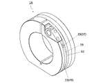
- the unit 1 may have a plurality of holders 23.
- Each of the plurality of holders 23 may be cylindrical.
- the plurality of holders 23 may be attached to the first shaft member 5 respectively.
- the plurality of holders 23 may be detachably attached to the first shaft member 5 . Holders 23 adjacent to each other may be in contact or may be separated from each other.
- the number of holders 23 may be 2-30.
- the holder 23 may be a member for fixing the first cutting edge member 25 described below to the first shaft member 5 .
- the unit 1 may have a plurality of first cutting edge members 25.
- Each of the plurality of first cutting blade members 25 may have an annular shape.
- the plurality of first cutting blade members 25 may be attached to the plurality of holders 23, respectively.
- the plurality of first cutting blade members 25 may be detachably attached to the plurality of holders 23, respectively.
- the number of first cutting blade members 25 may be 2-30.
- the number of first cutting blade members 25 may be the same as the number of holders 23 .
- the first cutting blade member 25 may be a disc-shaped or dish-shaped member.
- the first cutting blade member 25 may also be referred to as a circular blade.
- the plurality of first cutting edge members 25 When a plurality of holders 23 are attached to the first shaft member 5, respectively, and a plurality of first cutting edge members 25 are attached to the plurality of holders 23, the plurality of first cutting edge members 25 are , can be fixed to the first shaft member 5 via a plurality of holders 23, respectively. Therefore, when the first shaft member 5 rotates, the plurality of first cutting blade members 25 can also rotate in accordance with the rotation of the first shaft member 5 . Further, when the interval between the holders 23 adjacent to each other is adjusted, the interval between the first cutting blade members 25 adjacent to each other can also be adjusted accordingly.
- the unit 1 may have a plurality of second cutting edge members 27.
- Each of the plurality of second cutting blade members 27 may have a cylindrical shape.
- the plurality of second cutting blade members 27 may be attached to the second shaft member 7 respectively.
- the plurality of second cutting blade members 27 may be detachably attached to the second shaft member 7 .
- the plurality of second cutting blade members 27 are also rotatable according to the rotation of the second shaft member 7 .
- the number of second cutting edge members 27 may be 2-30.
- the plurality of second cutting edge members 27 may be attached to the second shaft member 7 so that the side surfaces of the plurality of second cutting edge members 27 are in contact with the side surfaces of the plurality of first cutting edge members 25, respectively.
- the side surface of the first cutting edge member 25, which is relatively elastically deformable, and the side surface of the second cutting edge member 27, which is relatively difficult to elastically deform come into contact with each other. Shear forces can occur between 25 and the second cutting member 27 . This shearing force makes it possible to cut the sheet-shaped member. Therefore, the relatively wide sheet-like member sent to the unit 1 is cut by the plurality of first cutting blade members 25 and the plurality of second cutting blade members 27 to process the relatively narrow sheet. It becomes possible to make things (cut pieces).
- first shaft member 5, the second shaft member 7, the first cutting blade member 25, and the second cutting blade member 27 may each have conductivity.
- the first shaft member 5, the second shaft member 7, the first cutting blade member 25, and the second cutting blade member 27 may be made of a conductive material.
- Materials having conductivity include, for example, copper, steel, stainless steel, and aluminum.
- first shaft member 5, the second shaft member 7, the first cutting edge member 25, and the second cutting edge member 27 may have conductivity.
- first shaft member 5, the second shaft member 7, the first cutting blade member 25, and the second cutting blade member 27 are arranged on a base having an insulating property and positioned on the base and having conductivity. and a coating film.
- Examples of materials for the substrate having insulating properties include resins, ceramics, and DLC (Diamond like Carbon).
- Resins may include, for example, polyethylene, polypropylene, polystyrene, and polyvinyl chloride.
- Ceramics may include, for example, alumina (Al 2 O 3 ), zirconia (ZrO 2 ), aluminum nitride (AlN), silicon carbide (SiC) and silicon nitride (Si 3 N 4 ).
- examples of the material of the conductive coating film include a Ti-based coating containing Ti. Examples of Ti-based coatings include TiN, TiC, TiCN, TiAlN, TiAlCN and TiAlON.
- a conductive coating film may be called a conductive film. The coating film may be placed on the substrate by using chemical vapor deposition (CVD) or physical vapor deposition (PVD) methods.
- CVD chemical vapor deposition
- PVD physical vapor deposition
- At least one of the first shaft member 5, the second shaft member 7, the first cutting blade member 25, and the second cutting blade member 27 is made of a conductive material, and the remaining members are made of an insulating material. and a conductive coating film located on the substrate.
- the unit 1 may have detection means 29 for detecting contact between the plurality of first cutting edge members 25 and the plurality of second cutting edge members 27 .
- the detection means 29 may have a power supply 31, a first wiring 33, a second wiring 35, a light emitting member 37, a third wiring 39 and a fourth wiring 41, as in a non-limiting example shown in FIGS. good.
- the first wiring 33 may electrically connect the first shaft member 5 and the power source 31 .
- the second wiring 35 may electrically connect the second shaft member 7 and the power supply 31 .
- a plurality of light emitting members 37 may be provided.
- the plurality of light emitting members 37 may be attached to the plurality of holders 23 respectively.
- the third wiring 39 may electrically connect the plurality of light emitting members 37 and the first shaft member 5 respectively.
- the fourth wiring 41 may electrically connect the plurality of light emitting members 37 and the plurality of first cutting edge members 25 respectively.
- the plurality of light emitting members 37 are attached to the plurality of holders 23 instead of the base 3, even if the number and positions of the plurality of first cutting edge members 25 are changed, the light emitting members 37 and The correspondence relationship of the first cutting blade members 25 is easy to understand.
- the plurality of light emitting members 37 can emit light individually. Therefore, individual detection can be performed to individually detect the presence or absence of contact between the plurality of first cutting blade members 25 and the plurality of second cutting blade members 27, instead of the overall detection of collectively detecting the presence or absence of contact. Therefore, it is easy to efficiently detect the presence or absence of contact between the plurality of first cutting blade members 25 and the plurality of second cutting blade members 27, and it is easy to suppress the occurrence of defective cutting.
- the light emitting member 37 may be a lamp.
- the number of light emitting members 37 may be 2-30.
- the number of light emitting members 37 may be the same as the number of holders 23 .
- the holder 23 may have insulating properties. In this case, the holder 23 is less likely to be electrically short-circuited with the first shaft member 5 . Moreover, it is easy to form the third wiring 39 .
- the holder 23 may be made of an insulating material. As the insulating material, for example, the same materials as those exemplified for the substrate having insulating properties can be mentioned.
- the holder 23 may have an insulating surface.
- the main body 43 of the holder 23 may be conductive, and the coating film 47 may be insulating.
- the material of the main body 43 having conductivity for example, the same materials as those exemplified for the first shaft member 5 can be used.
- examples of the material of the insulating coating film 47 include resin, ceramics, and DLC (Diamond-like Carbon). Note that the insulating coating film 47 may be positioned on other surfaces of the main body 43 in addition to the inner peripheral surface 45 .
- the insulating coating film 47 may also be called an insulating film.
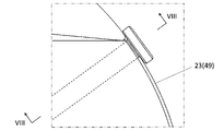
- the holder 23 may have an outer peripheral surface 49 as in a non-limiting example shown in FIG.
- the body 43 of the holder 23 may have an outer peripheral surface 49 .
- the light emitting member 37 may be attached to the outer peripheral surface 49 . In this case, the light-emitting member 37 is easily visible.
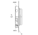
- the third wiring 39 may have a ball plunger 51 capable of contacting the first shaft member 5, like a non-limiting example shown in FIG. In this case, it is easy to make contact with the first shaft member 5 (shaft) at one point.
- the ball plunger 51 may have conductivity. Also, the ball plunger 51 may have a ball 53 that can contact the first shaft member 5 and a biasing means 55 that biases the ball 53 toward the first shaft member 5 .
- the biasing means 55 may include, for example, a spring.
- the plurality of light emitting members 37 may be arranged in a line along the first rotation axis O1, as in a non-limiting example shown in FIG. In this case, the light-emitting member 37 is easily visible.
- the detection means 29 may have a switch 57.
- the switch 57 can turn on/off the flow of current. If the detecting means 29 has the switch 57, it can be activated only when the position of the cutting edge is to be checked. In addition, the position of the switch 57 is not particularly limited as long as the function is exhibited.
- unit 1A a cutting device unit 1A (hereinafter sometimes referred to as "unit 1A"), which is not limited to the present disclosure, will be described with reference to FIGS. 10 and 11.
- FIG. 10 and 11 a cutting device unit 1A (hereinafter sometimes referred to as "unit 1A"), which is not limited to the present disclosure, will be described with reference to FIGS. 10 and 11.
- FIG. 10 and 11 differences between the unit 1A and the unit 1 will be mainly described, and detailed descriptions of the points having the same configuration as the unit 1 may be omitted.
- the holder 23 may have an annular recess 59 located on the outer peripheral surface 49, as in a non-limiting example shown in FIGS.
- the light emitting member 37 may be attached to the recess 59 . In these cases, the light emitting member 37 is less likely to be damaged.
- the concave portion 59 may also be called a groove.
- the unit 1A may further have a translucent member 61.
- the translucent member 61 may be attached to the recess 59 and may have an annular shape covering the light emitting member 37 . In this case, the light emitting member 37 is less likely to be damaged.
- Examples of materials for the translucent member 61 include glass and translucent resin.
- Examples of translucent resins include PMMA (PolyMethyl MethAcrylate: acrylic) resin, PET (PolyEthylene Terephthalate: polyethylene terephthalate) resin, and PC (PolyCarbonate: polycarbonate) resin.
- the translucency of the translucent member 61 may be such that the light emitting member 37 can be visually recognized through the translucent member 61 .
- the plurality of light emitting members 37 may each have a first light emitting element 63 and a second light emitting element 65 .
- the second light emitting element 65 may emit light in a color different from that of the first light emitting element 63 . In these cases, it is possible to separately display the usage and positional relationship of the cutting tool at the cutting site.
- the cutting device 101 may have a unit 1, a first roll 103 and a second roll 105, as in a non-limiting example shown in FIG.
- poor cutting is less likely to occur.
- the sheet-like member 201 may be wound around the first roll 103 , or the sheet-like member 201 may be delivered to the unit 1 .
- the first roll 103 can function as a supply mechanism for supplying the sheet-like member 201 to the unit 1 .
- the sheet-like member 201 wound around the first roll 103 may be delivered to the unit 1 by rotating the first roll 103 .
- the second roll 105 may wind the sheet-shaped member 201 cut by the unit 1 .
- the second roll 105 can function as a winding mechanism for winding the sheet-shaped member 201 cut by the unit 1 .
- the number of the second rolls 105 may be one, or may be plural. When the number of the second rolls 105 is one, the sheet-like members 201 cut into individual pieces by the unit 1 may be collectively wound around the single second roll 105 . Moreover, when there are a plurality of second rolls 105 , the sheet-like member 201 cut into individual pieces by the unit 1 may be wound around the plurality of second rolls 105 .
- the sheet-shaped member 201 cut into individual pieces by the unit 1 may be referred to as a sheet processed product 203 .
- the cutting device 101 may have a first guide roll 107 positioned between the unit 1 and the first roll 103 .
- the first guide roll 107 may be composed of one roll, or may be composed of a plurality of rolls.
- the cutting device 101 may have a second guide roll 109 positioned between the unit 1 and the second roll 105 .
- the sheet workpiece 203 can be conveyed from the unit 1 to the second roll 105 through the second guide roll 109, so that the conveying state of the sheet workpiece 203 is easily stabilized.
- the second guide roll 109 may be composed of one roll, or may be composed of a plurality of rolls.
- the cutting device 101 has the unit 1 in the non-limiting example shown in FIG. 12, it is not limited to such a form.
- the cutting device 101 may have the unit 1A.
- the sheet workpiece 203 may be produced by cutting a sheet-like member 201, as shown in FIG. 12 as a non-limiting example.
- the method for manufacturing the sheet workpiece 203 may include the following steps. i.e. (1) a step of inserting the sheet-shaped member 201 between the plurality of first cutting blade members 25 and the plurality of second cutting blade members 27 in the unit 1 of the cutting device 101; (2) cutting the sheet-shaped member 201 with the plurality of first cutting blade members 25 and the plurality of second cutting blade members 27; may be provided.
- the cutting device 101 having the unit 1 When the cutting device 101 having the unit 1 is used in the method of manufacturing the sheet workpiece 203, poor cutting is less likely to occur.
- the first roll 103 By rotating the first roll 103 , it becomes possible to insert the sheet-like member 201 between the first cutting blade member 25 and the second cutting blade member 27 in the unit 1 . Further, the sheet workpiece 203 can be wound around the second roll 105 by rotating the second roll 105 .
- Examples of the sheet-like member 201 include members such as metal foil, paper, and resin film.
- the cutting device 101 having the unit 1 is used in a non-limiting example shown in FIG. 12, the present invention is not limited to such a form.
- a cutting device 101 having a unit 1A may be used.
Landscapes
- Life Sciences & Earth Sciences (AREA)
- Forests & Forestry (AREA)
- Engineering & Computer Science (AREA)
- Mechanical Engineering (AREA)
- Nonmetal Cutting Devices (AREA)
- Details Of Cutting Devices (AREA)
- Finish Polishing, Edge Sharpening, And Grinding By Specific Grinding Devices (AREA)
- Constituent Portions Of Griding Lathes, Driving, Sensing And Control (AREA)
- Dicing (AREA)
- Perforating, Stamping-Out Or Severing By Means Other Than Cutting (AREA)
Priority Applications (4)
| Application Number | Priority Date | Filing Date | Title |
|---|---|---|---|
| US18/554,995 US12508731B2 (en) | 2021-04-19 | 2022-04-05 | Unit for cutting apparatus and cutting apparatus |
| JP2023516424A JP7499410B2 (ja) | 2021-04-19 | 2022-04-05 | 切断装置用ユニット及び切断装置 |
| KR1020237033729A KR102829934B1 (ko) | 2021-04-19 | 2022-04-05 | 절단 장치용 유닛 및 절단 장치 |
| CN202280028519.3A CN117136125B (zh) | 2021-04-19 | 2022-04-05 | 切断装置用单元以及切断装置 |
Applications Claiming Priority (2)
| Application Number | Priority Date | Filing Date | Title |
|---|---|---|---|
| JP2021070436 | 2021-04-19 | ||
| JP2021-070436 | 2021-04-19 |
Publications (1)
| Publication Number | Publication Date |
|---|---|
| WO2022224813A1 true WO2022224813A1 (ja) | 2022-10-27 |
Family
ID=83722238
Family Applications (1)
| Application Number | Title | Priority Date | Filing Date |
|---|---|---|---|
| PCT/JP2022/017081 Ceased WO2022224813A1 (ja) | 2021-04-19 | 2022-04-05 | 切断装置用ユニット及び切断装置 |
Country Status (5)
| Country | Link |
|---|---|
| US (1) | US12508731B2 (https=) |
| JP (1) | JP7499410B2 (https=) |
| KR (1) | KR102829934B1 (https=) |
| CN (1) | CN117136125B (https=) |
| WO (1) | WO2022224813A1 (https=) |
Cited By (1)
| Publication number | Priority date | Publication date | Assignee | Title |
|---|---|---|---|---|
| WO2024070873A1 (ja) * | 2022-09-27 | 2024-04-04 | 京セラ株式会社 | 切断装置用ユニット、切断装置及びシート断片の製造方法 |
Families Citing this family (1)
| Publication number | Priority date | Publication date | Assignee | Title |
|---|---|---|---|---|
| CN116787532A (zh) * | 2023-06-26 | 2023-09-22 | 杭州东洋精密刀具有限公司 | 一种刀具安装结构及其安装方法 |
Citations (6)
| Publication number | Priority date | Publication date | Assignee | Title |
|---|---|---|---|---|
| JPH04122488U (ja) * | 1991-04-17 | 1992-11-04 | 東洋刃物株式会社 | シートスリツター装置 |
| JPH0512096U (ja) * | 1991-07-30 | 1993-02-19 | 東洋刃物株式会社 | スリツター薄刃の側圧制御装置 |
| US20020017174A1 (en) * | 2000-08-02 | 2002-02-14 | Gammerler Ag | Cutting apparatus |
| JP2012071414A (ja) * | 2010-08-31 | 2012-04-12 | Kataoka Mach Co Ltd | スリッター装置の上刃位置変更方法及びスリッター装置 |
| JP2012121098A (ja) * | 2010-12-08 | 2012-06-28 | Toray Eng Co Ltd | シート状物の切断装置 |
| WO2016114343A1 (ja) * | 2015-01-14 | 2016-07-21 | 京セラ株式会社 | 回転刃用ホルダ、切断装置用ユニット及び切断装置 |
Family Cites Families (17)
| Publication number | Priority date | Publication date | Assignee | Title |
|---|---|---|---|---|
| JPH0757477B2 (ja) | 1988-06-21 | 1995-06-21 | 東芝タンガロイ株式会社 | テープスリッター装置 |
| JP3076360B2 (ja) * | 1990-08-21 | 2000-08-14 | 株式会社ブリヂストン | コード入りゴムシートの切断不良検出方法 |
| DE19958274B4 (de) * | 1999-12-03 | 2006-11-23 | Hengstler Gmbh | Abschneider für klebende Etiketten |
| JP2005254381A (ja) | 2004-03-11 | 2005-09-22 | Konica Minolta Medical & Graphic Inc | 裁断装置及び円盤状上刃と円筒状下刃との接触力設定方法 |
| US20050217447A1 (en) * | 2004-03-31 | 2005-10-06 | R. J. Reynolds Tobacco Company | Slitter device with adjustable blade |
| DE502004008416D1 (de) * | 2004-09-20 | 2008-12-18 | Mueller Martini Holding Ag | Rotationsschneidemaschine mit Verstellvorrichtung zum Einstellen des Schnittspaltes der Messer in Längsrichtung der Messerwellen |
| TWI258413B (en) * | 2005-06-24 | 2006-07-21 | Primax Electronics Ltd | Marking device |
| US7735403B2 (en) * | 2006-09-26 | 2010-06-15 | Robert Bosch Gmbh | Alignment system for a fence for a table saw |
| TWI330123B (en) * | 2007-11-23 | 2010-09-11 | Primax Electronics Ltd | Method for detecting whether object is completely cut off and paper cutter therewith |
| US8381623B2 (en) * | 2009-12-15 | 2013-02-26 | Fiskars Brands, Inc. | Material trimmer with illuminated cut line indicator |
| US8312798B2 (en) * | 2010-05-18 | 2012-11-20 | Eastman Kodak Company | Slitter with translating cutting devices |
| JP5717905B1 (ja) * | 2014-09-05 | 2015-05-13 | 株式会社大矢根利器製作所 | ラベルシート切断装置 |
| JP6927574B2 (ja) * | 2016-09-21 | 2021-09-01 | デュプロ精工株式会社 | スリッタ、シート裁断機、及びシート加工装置 |
| US10201256B2 (en) * | 2017-07-11 | 2019-02-12 | Guangzhou Faner Aroma Product Co., Ltd. | Paper cutting device easy to be disassembled and maintained |
| US11833632B2 (en) * | 2018-07-18 | 2023-12-05 | Illinois Tool Works Inc. | Method and apparatus for maintaining a surface speed of a circular cutting device |
| KR102196059B1 (ko) * | 2020-06-05 | 2020-12-29 | 이석현 | 진단 킷용 스트립 절단 장치 |
| CN111715928B (zh) * | 2020-07-11 | 2025-07-22 | 四川神工钨钢刀具有限公司 | 一种刀片调节机构、电池分切装置和对刀方法 |
-
2022
- 2022-04-05 KR KR1020237033729A patent/KR102829934B1/ko active Active
- 2022-04-05 CN CN202280028519.3A patent/CN117136125B/zh active Active
- 2022-04-05 WO PCT/JP2022/017081 patent/WO2022224813A1/ja not_active Ceased
- 2022-04-05 JP JP2023516424A patent/JP7499410B2/ja active Active
- 2022-04-05 US US18/554,995 patent/US12508731B2/en active Active
Patent Citations (6)
| Publication number | Priority date | Publication date | Assignee | Title |
|---|---|---|---|---|
| JPH04122488U (ja) * | 1991-04-17 | 1992-11-04 | 東洋刃物株式会社 | シートスリツター装置 |
| JPH0512096U (ja) * | 1991-07-30 | 1993-02-19 | 東洋刃物株式会社 | スリツター薄刃の側圧制御装置 |
| US20020017174A1 (en) * | 2000-08-02 | 2002-02-14 | Gammerler Ag | Cutting apparatus |
| JP2012071414A (ja) * | 2010-08-31 | 2012-04-12 | Kataoka Mach Co Ltd | スリッター装置の上刃位置変更方法及びスリッター装置 |
| JP2012121098A (ja) * | 2010-12-08 | 2012-06-28 | Toray Eng Co Ltd | シート状物の切断装置 |
| WO2016114343A1 (ja) * | 2015-01-14 | 2016-07-21 | 京セラ株式会社 | 回転刃用ホルダ、切断装置用ユニット及び切断装置 |
Cited By (1)
| Publication number | Priority date | Publication date | Assignee | Title |
|---|---|---|---|---|
| WO2024070873A1 (ja) * | 2022-09-27 | 2024-04-04 | 京セラ株式会社 | 切断装置用ユニット、切断装置及びシート断片の製造方法 |
Also Published As
| Publication number | Publication date |
|---|---|
| US20240198552A1 (en) | 2024-06-20 |
| CN117136125A (zh) | 2023-11-28 |
| KR102829934B1 (ko) | 2025-07-04 |
| JPWO2022224813A1 (https=) | 2022-10-27 |
| JP7499410B2 (ja) | 2024-06-13 |
| KR20230154233A (ko) | 2023-11-07 |
| CN117136125B (zh) | 2025-11-07 |
| US12508731B2 (en) | 2025-12-30 |
Similar Documents
| Publication | Publication Date | Title |
|---|---|---|
| JP7499410B2 (ja) | 切断装置用ユニット及び切断装置 | |
| CN101852611B (zh) | 应用于工具的同源双线标线装置及其标线方法 | |
| US20170263803A1 (en) | Edgelit Multi-Panel Lighting System | |
| US20170031080A1 (en) | Edge-Lit Stepped Light Guide for Downlight Module | |
| CN103968281A (zh) | 照明器具及光源单元 | |
| JP4449036B2 (ja) | 面状照明装置 | |
| KR20250048466A (ko) | 절단 장치용 유닛, 절단 장치 및 시트 단편의 제조 방법 | |
| CN109849196B (zh) | 划线轮、刀尖支架及支承销 | |
| US20150260928A1 (en) | Fiber optic epoxy cutting tool and method of use | |
| JP4480029B2 (ja) | ライン光照射装置 | |
| WO2016114343A1 (ja) | 回転刃用ホルダ、切断装置用ユニット及び切断装置 | |
| JP6232584B2 (ja) | スプライシングテープ用のテープカッター | |
| CN112867892A (zh) | 照明系统 | |
| KR102520519B1 (ko) | 반사판 제조장치 | |
| JP2022071017A (ja) | スリッターナイフおよびスリッター | |
| JP6371946B2 (ja) | 照明装置 | |
| CN201488733U (zh) | 应用于工具的同源双线标线装置 | |
| CN104057547B (zh) | 加工夹具、加工装置及加工方法 | |
| CN201716024U (zh) | 应用于工具的同源双线标线装置 | |
| JP2007083248A (ja) | レーザ加工装置及びレーザ加工方法 | |
| JP2025132129A (ja) | ロータリーカッター装置 | |
| JPH04122488U (ja) | シートスリツター装置 | |
| JP5791137B1 (ja) | 回転カッター芯出ユニット及び被覆ケーブルの被覆剥離装置 | |
| JPWO2024070873A5 (https=) | ||
| JP2023140810A (ja) | 金型、加工方法、及びレーザ複合加工機 |
Legal Events
| Date | Code | Title | Description |
|---|---|---|---|
| 121 | Ep: the epo has been informed by wipo that ep was designated in this application |
Ref document number: 22791588 Country of ref document: EP Kind code of ref document: A1 |
|
| WWE | Wipo information: entry into national phase |
Ref document number: 2023516424 Country of ref document: JP |
|
| ENP | Entry into the national phase |
Ref document number: 20237033729 Country of ref document: KR Kind code of ref document: A |
|
| WWE | Wipo information: entry into national phase |
Ref document number: 1020237033729 Country of ref document: KR |
|
| WWE | Wipo information: entry into national phase |
Ref document number: 18554995 Country of ref document: US |
|
| NENP | Non-entry into the national phase |
Ref country code: DE |
|
| 122 | Ep: pct application non-entry in european phase |
Ref document number: 22791588 Country of ref document: EP Kind code of ref document: A1 |
|
| WWG | Wipo information: grant in national office |
Ref document number: 202280028519.3 Country of ref document: CN |
|
| WWG | Wipo information: grant in national office |
Ref document number: 18554995 Country of ref document: US |