WO2022224393A1 - 誘電加熱電極及び誘電加熱装置 - Google Patents
誘電加熱電極及び誘電加熱装置 Download PDFInfo
- Publication number
- WO2022224393A1 WO2022224393A1 PCT/JP2021/016263 JP2021016263W WO2022224393A1 WO 2022224393 A1 WO2022224393 A1 WO 2022224393A1 JP 2021016263 W JP2021016263 W JP 2021016263W WO 2022224393 A1 WO2022224393 A1 WO 2022224393A1
- Authority
- WO
- WIPO (PCT)
- Prior art keywords
- heated
- dielectric
- dielectric heating
- electrode
- electrodes
- Prior art date
- Legal status (The legal status is an assumption and is not a legal conclusion. Google has not performed a legal analysis and makes no representation as to the accuracy of the status listed.)
- Ceased
Links
Images


Classifications
-
- H—ELECTRICITY
- H05—ELECTRIC TECHNIQUES NOT OTHERWISE PROVIDED FOR
- H05B—ELECTRIC HEATING; ELECTRIC LIGHT SOURCES NOT OTHERWISE PROVIDED FOR; CIRCUIT ARRANGEMENTS FOR ELECTRIC LIGHT SOURCES, IN GENERAL
- H05B6/00—Heating by electric, magnetic or electromagnetic fields
- H05B6/46—Dielectric heating
- H05B6/54—Electrodes
Definitions
- the present disclosure relates to dielectric heating electrodes and dielectric heating devices.
- Patent Document 1 Conventionally, a method of heating an object to be heated by sandwiching it between two electrodes has been provided. Such a heating method is disclosed in Patent Document 1, for example.
- the dielectric heating electrodes according to the present disclosure include a pair of electrodes arranged facing each other, sandwiching a passage body to be heated that supplies an object to be heated, and a pair of electrodes arranged between each electrode and the passage body to be heated. It comprises a dielectric and a heat insulating layer respectively arranged between each electrode and the heated passage body.
- FIG. 1 is a diagram showing a configuration of a dielectric heating device provided with dielectric heating electrodes according to Embodiment 1.
- FIG. FIG. 10 is a diagram showing the configuration of a dielectric heating device provided with dielectric heating electrodes according to Embodiment 2;
- FIG. 10 is a diagram showing the configuration of a dielectric heating device provided with dielectric heating electrodes according to Embodiment 3;
- FIG. 10 is a diagram showing the configuration of a dielectric heating device according to Embodiment 4;
- FIG. 10 is a diagram showing another configuration of the dielectric heating device according to Embodiment 4;
- FIG. 1 is a diagram showing the configuration of a dielectric heating device 100 including a dielectric heating electrode 10 according to Embodiment 1.
- FIG. 1 is a diagram showing the configuration of a dielectric heating device 100 including a dielectric heating electrode 10 according to Embodiment 1.
- a dielectric heating apparatus 100 heats an object X to be heated using high frequency dielectric.
- This dielectric heating device 100 comprises a dielectric heating electrode 10 , a passage body 60 to be heated, and a signal source 70 .
- the dielectric heating electrode 10 heats the sandwiched heated passage body 60 , and finally heats the object X flowing inside the heated passage body 60 . and evaporate it. Details of the dielectric heating electrode 10 will be described later.
- the passage body 60 to be heated is heated by the dielectric heating electrodes 10 by being sandwiched by the dielectric heating electrodes 10 from both sides in the width direction. Further, the heated passage body 60 has a function of passing a high frequency voltage but not passing a DC component.
- the heated passage body 60 is made of, for example, glass fiber, linen, cotton, or the like. Such a heated passage body 60 is formed by bundling a plurality of supply passages 61 into one.
- the plurality of supply passages 61 extend in the longitudinal direction of the passage body 60 to be heated. These supply passages 61 supply the object X to be heated from one end side of the passage body 60 to be heated to the other end side.
- the discharge port 62 is formed on the upper surface of the passage body 60 to be heated. This discharge port 62 communicates with each supply passage 61 . Therefore, the discharge port 62 can discharge the vaporized object to be heated X to the outside of the passage body 60 to be heated.
- the signal source 70 outputs a high frequency signal.
- One end of the signal source 70 is connected to one end of the dielectric heating electrode 10 .
- the other end of the signal source 70 is connected to the other end of the dielectric heating electrode 10 .
- the signal source 70 is configured such that a high-frequency signal output from one end returns to the other end via the dielectric heating electrode 10, and is applicable to both single-phase circuits and differential circuits. is.
- the dielectric heating electrode 10 includes a pair of electrodes 11a and 11b, support members 12a and 12b, high dielectrics 13a and 13b, and heat insulating layers 14a and 14b so as to face each other.
- the electrode 11a, the support member 12a, the high dielectric 13a, and the heat insulating layer 14a are arranged on one end side of the dielectric heating electrode 10 with the passage body 60 to be heated as a boundary. At this time, the electrode 11a, the high dielectric 13a, and the heat insulation layer 14a are arranged in order from the outside of the dielectric heating electrode 10 toward the inside (the heated passage body 60 side).
- the electrode 11b, the support member 12b, the high dielectric 13b, and the heat insulating layer 14b are arranged on the other end side of the dielectric heating electrode 10 with the passage body 60 to be heated as a boundary. At this time, the electrode 11b, the high dielectric 13b, and the heat insulation layer 14b are arranged in order from the outside of the dielectric heating electrode 10 toward the inside (the heated passage body 60 side).
- the support members 12a and 12b are not electrically connected to each other.
- the support members 12a and 12b have a low dielectric constant and a low loss function.
- the support members 12a and 12b are made of resin, ceramic, glass, or the like, for example.
- the high dielectric 13a is connected to the electrode 11a and supported by the support member 12a.
- High dielectric 13b is connected to electrode 11b and supported by support member 12b.
- the high dielectrics 13a and 13b have the function of passing high frequency voltages but not passing DC components.
- the high dielectrics 13a and 13b are made of ceramics, fine ceramics, or the like.
- the dielectric heating electrode 10 configured as described above, high-frequency components pass between the electrodes 11a and 11b, but DC components do not. Further, since the heat insulating layers 14a and 14b are interposed between the passage body 60 to be heated and the object to be heated X and the high dielectrics 13a and 13b, they are thermally separated from the heat insulating layers 14a and 14b. ing. At this time, the dielectric heating electrode 10 is provided so that the entire discharge port 62 is included in the region of the passage body 60 to be heated between the high dielectrics 13a and 13b.
- the high-frequency signal output from one end of the signal source 70 is input to the electrode 11a and then passes through the high dielectric 13a, the heat insulating layer 14a, and the passage body 60 to be heated. do. Furthermore, the high-frequency signal that has passed through the heated passage body 60 returns to the other end of the signal source 70 via the heat insulation layer 14b, the high dielectric material 13b, and the electrode 11b.
- the heat generated in the object to be heated X is transferred to the electrodes 11a and 11b and the support members 12a and 12b. is not transmitted to That is, the electrodes 11a and 11b and the support members 12a and 12b are not deformed by the heat generated by the object X to be heated.
- the passage body 60 to be heated is heated until it reaches the same temperature as the object X to be heated.
- the passage body 60 to be heated is heated to the temperature of the object X to be heated in this manner, heat transfer from the object X to be heated to the passage body 60 to be heated ceases.
- the dielectric heating electrode 10 can heat the object X to be heated efficiently.
- the dielectric heating electrode 10 discharges the vaporized material X to be heated from the discharge port 62, and continues to supply new material X to be heated between the electrodes 11a and 11b through the supply passage 61, so that the material to be heated X can be continuously vaporized.
- the dielectric heating electrode 10 according to Embodiment 1 described above includes one passage body 60 to be heated, a plurality of passage bodies 60 to be heated may be provided. In this case, a plurality of heated passage bodies 60 are provided in parallel. On the other hand, the dielectric heating electrodes 10 collectively sandwich the plurality of heated passage bodies 60 provided in parallel.
- the dielectric heating electrode 10 includes a pair of electrodes 11a and 11b arranged facing each other with the passage body 60 to be heated that supplies the object X to be heated sandwiched therebetween, and the electrodes 11a and 11b.
- High dielectrics 13a, 13b are arranged between the passage body 60 to be heated, and heat insulating layers 14a, 14b are arranged between the electrodes 11a, 11b and the passage body 60 to be heated, respectively. Therefore, the dielectric heating electrode 10 can suppress the heat conduction from the object X to be heated to the electrodes 11a and 11b, and can improve the efficiency of heating the object X to be heated.
- the heat insulating layers 14a and 14b are layers of air. Therefore, the dielectric heating electrode 10 can suppress heat conduction from the object to be heated X to the electrodes 11a and 11b with a simple structure.
- the passage body 60 to be heated has a plurality of supply passages 61 formed of fibers into which the object X to be heated can permeate. Therefore, the dielectric heating electrode 10 can efficiently supply the object X to be heated.
- the passage body 60 to be heated has a discharge port 62 for discharging the vaporized material X to be heated from the supply passage 61 to the outside. Therefore, the dielectric heating electrode 10 can release the vaporized object X to be heated to the outside of the passage body 60 to be heated.
- the discharge port 62 is formed so as to be sandwiched between the high dielectrics 13a and 13b. Therefore, the dielectric heating electrode 10 can efficiently discharge the vaporized object X to be heated.
- FIG. 2 is a diagram showing the configuration of a dielectric heating device 200 including the dielectric heating electrode 20 according to Embodiment 2. As shown in FIG. It should be noted that configurations having functions similar to those of the configuration described in Embodiment 1 are denoted by the same reference numerals, and description thereof will be omitted.
- the dielectric heating electrode 20 has the same constituent members as the dielectric heating electrode 10 according to Embodiment 1, but the installation position is different.
- the components having different installation positions are the high dielectrics 13a and 13b and the heat insulating layers 14a and 14b.
- the electrode 11a, the heat insulating layer 14a, and the high dielectric 13a extend from the outside of the dielectric heating electrode 20 toward the inside (the heated passage body 60 side). are arranged in order.
- the electrode 11b, the heat insulating layer 14b, and the high dielectric 13b are arranged in order from the outside to the inside of the dielectric heating electrode 20. As shown in FIG.
- the passage body 60 to be heated and the high dielectric substance 13a, and the passage body 60 to be heated and the high dielectric substance 13b are in contact with each other, so that they are thermally connected.
- heat insulating layers 14a and 14b are interposed between the high dielectric 13a and the electrode 11a and between the high dielectric 13b and the electrode 11b, so that they are thermally isolated. Therefore, the heat generated by the object X to be heated is not transmitted to the electrodes 11a and 11b and the support members 12a and 12b. That is, the electrodes 11a and 11b and the support members 12a and 12b are not deformed by the heat generated by the object X to be heated. High frequency components pass between the electrodes 11a and 11b, but DC components do not.
- the dielectric heating electrode 20 includes a pair of electrodes 11a and 11b arranged facing each other with the passage body 60 to be heated that supplies the object X to be heated sandwiched therebetween, and the electrodes 11a and 11b.
- High dielectrics 13a, 13b are arranged between the passage body 60 to be heated, and heat insulating layers 14a, 14b are arranged between the electrodes 11a, 11b and the passage body 60 to be heated, respectively. Therefore, the dielectric heating electrode 10 can suppress the heat conduction from the object X to be heated to the electrodes 11a and 11b, and can improve the efficiency of heating the object X to be heated.
- FIG. 3 is a diagram showing the configuration of a dielectric heating device 300 including the dielectric heating electrode 30 according to Embodiment 3. As shown in FIG. It should be noted that configurations having functions similar to those of the configuration described in Embodiment 1 are denoted by the same reference numerals, and description thereof will be omitted.
- a dielectric heating device 300 according to Embodiment 3 shown in FIG. 3 heats an object X to be heated using high frequency dielectric.
- This dielectric heating device 300 comprises a dielectric heating electrode 30 , a heated passage body 60 and a signal source 70 . That is, the dielectric heating device 300 includes the dielectric heating electrode 30 instead of the dielectric heating electrode 10 of the dielectric heating device 100 according to the first embodiment.
- the dielectric heating electrode 30 has a configuration in which high dielectric materials 15a and 15b are added to the configuration of the dielectric heating electrode 10 according to the first embodiment.
- the high dielectrics 13a and 13b constitute a first high dielectric
- the high dielectrics 15a and 15b constitute a second high dielectric.
- the electrode 11a, the high dielectric 13a, the heat insulating layer 14a, and the high dielectric 15a extend from the outside of the dielectric heating electrode 20 to the inside (heated passage body 60). side).
- the electrode 11b, the high dielectric 13b, the heat insulating layer 14b, and the high dielectric 15b extend from the outside of the dielectric heating electrode 20 to the inside (the heated passage body 60 side). are arranged in order.
- the high dielectric 15a is supported in contact with the heat insulating layer 14a.
- the high dielectric 15b is supported in contact with the heat insulating layer 14b.
- the high dielectrics 15a and 15b are in contact with the respective side surfaces of the passage body 60 to be heated, and sandwich the passage body 60 to be heated from both sides in the width direction thereof.
- the dielectric heating electrode 30 is provided so that the entire discharge port 62 is included in the region of the passage body 60 to be heated between the high dielectrics 15a and 15b.
- the passage body 60 to be heated and the high dielectric 15a, and the passage body 60 to be heated and the high dielectric 15b are in contact with each other, so that they are thermally connected.
- thermal insulation layers 14a and 14b are interposed between the high dielectric 15a and the electrode 11a and between the high dielectric 15b and the electrode 11b, so that they are thermally isolated. Therefore, the heat generated by the object X to be heated is not transmitted to the electrodes 11a and 11b and the support members 12a and 12b. That is, the electrodes 11a and 11b and the support members 12a and 12b are not deformed by the heat generated by the object X to be heated. High frequency components pass between the electrodes 11a and 11b, but DC components do not.
- ⁇ r1 be the dielectric constant of the high dielectrics 13a and 13b
- tan ⁇ 1 be the dielectric loss tangent of the high dielectrics 13a and 13b.
- the dielectric constant of the high dielectrics 15a and 15b is ⁇ r2
- the dielectric loss tangent of the high dielectrics 13a and 13b is tan ⁇ 2.
- the magnitude relationship of the product of the dielectric constant and the dielectric loss tangent between the high dielectrics 13a and 13b and the high dielectrics 15a and 15b is [ ⁇ r1 ⁇ tan ⁇ 1 ⁇ r2 ⁇ tan ⁇ 2 ].
- both the high-dielectrics 13a and 13b and the high-dielectrics 15a and 15b generate heat when a high-frequency voltage is applied by the electrode 11a.
- the heat generated by the high dielectrics 13a and 13b is reduced and the heat generated by the high dielectrics 15a and 15b is increased. That is, the heat generated by the high dielectrics 15a and 15b is greater than the heat generated by the high dielectrics 13a and 13b. Therefore, the dielectric heating electrode 30 can suppress the transfer of heat from the high dielectrics 13a, 13b to the electrodes 11a, 11b, and can efficiently heat the object X to be heated by the high dielectrics 15a, 15b. .
- the dielectric heating electrode 30 includes two pairs of high dielectrics 13a and 13b and high dielectrics 15a and 15b, when the pair of high dielectrics 13a and 13b are provided like the dielectric heating electrode 10, The direction of the electric field generated between the electrodes 11a and 11b can be further concentrated toward the object X to be heated, as compared with the case of (1). As described above, when the electric field strength in the object X to be heated is improved, the energy applied to the object X to be heated is increased. As a result, the dielectric heating electrode 10 can heat the object X to be heated efficiently.
- the high dielectrics are composed of two pairs of the high dielectrics 13a and 13b and the high dielectrics 15a and 15b, and the heat insulation layers 14a and 14b are composed of a pair,
- the high dielectrics 13a, 13b are arranged between the electrodes 11a, 11b and the heat insulating layers 14a, 14b.
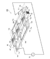
- FIG. 4 shows an example in which three dielectric heating electrodes 10 according to the first embodiment are provided.
- the three dielectric heating electrodes 10 are hereinafter referred to as dielectric heating electrodes 10a, 10b, and 10c.
- the dielectric heating device 400 includes three dielectric heating electrodes 10a, 10b, 10c, and corresponding discharge ports 62a, 62b, 62c are formed in one heated passage body 60. Therefore, the dielectric heating device 400 can increase the supply speed of the object X to be heated by the passage body 60 to be heated, so that the object X to be heated can be vaporized efficiently.
- the plurality of dielectric heating electrodes 10 are connected in parallel between one end and the other end of the signal source 70.
- a plurality of dielectric heating electrodes 10 may be connected in series between one end and the other end of the signal source 70 .
- the present disclosure can freely combine each embodiment, modify any component of each embodiment, or omit any component in each embodiment. .
Landscapes
- Physics & Mathematics (AREA)
- Electromagnetism (AREA)
- Constitution Of High-Frequency Heating (AREA)
Priority Applications (2)
| Application Number | Priority Date | Filing Date | Title |
|---|---|---|---|
| PCT/JP2021/016263 WO2022224393A1 (ja) | 2021-04-22 | 2021-04-22 | 誘電加熱電極及び誘電加熱装置 |
| JP2023515964A JP7309096B2 (ja) | 2021-04-22 | 2021-04-22 | 誘電加熱電極及び誘電加熱装置 |
Applications Claiming Priority (1)
| Application Number | Priority Date | Filing Date | Title |
|---|---|---|---|
| PCT/JP2021/016263 WO2022224393A1 (ja) | 2021-04-22 | 2021-04-22 | 誘電加熱電極及び誘電加熱装置 |
Publications (1)
| Publication Number | Publication Date |
|---|---|
| WO2022224393A1 true WO2022224393A1 (ja) | 2022-10-27 |
Family
ID=83723430
Family Applications (1)
| Application Number | Title | Priority Date | Filing Date |
|---|---|---|---|
| PCT/JP2021/016263 Ceased WO2022224393A1 (ja) | 2021-04-22 | 2021-04-22 | 誘電加熱電極及び誘電加熱装置 |
Country Status (2)
| Country | Link |
|---|---|
| JP (1) | JP7309096B2 (https=) |
| WO (1) | WO2022224393A1 (https=) |
Citations (4)
| Publication number | Priority date | Publication date | Assignee | Title |
|---|---|---|---|---|
| JPS53147453U (https=) * | 1977-04-26 | 1978-11-20 | ||
| JPS5442056U (https=) * | 1977-08-30 | 1979-03-20 | ||
| JPS61151289U (https=) * | 1985-03-12 | 1986-09-18 | ||
| JP6463570B1 (ja) * | 2018-05-15 | 2019-02-06 | 三菱電機株式会社 | 誘電加熱装置および誘電加熱電極 |
Family Cites Families (2)
| Publication number | Priority date | Publication date | Assignee | Title |
|---|---|---|---|---|
| JP2004261962A (ja) * | 2000-11-24 | 2004-09-24 | Idemitsu Petrochem Co Ltd | 高周波誘電加熱用金型、およびこれを用いた高周波融着加工製品の製造方法 |
| JP2017158533A (ja) * | 2016-03-02 | 2017-09-14 | 株式会社リコー | 除草装置および除草装置の制御方法 |
-
2021
- 2021-04-22 WO PCT/JP2021/016263 patent/WO2022224393A1/ja not_active Ceased
- 2021-04-22 JP JP2023515964A patent/JP7309096B2/ja active Active
Patent Citations (4)
| Publication number | Priority date | Publication date | Assignee | Title |
|---|---|---|---|---|
| JPS53147453U (https=) * | 1977-04-26 | 1978-11-20 | ||
| JPS5442056U (https=) * | 1977-08-30 | 1979-03-20 | ||
| JPS61151289U (https=) * | 1985-03-12 | 1986-09-18 | ||
| JP6463570B1 (ja) * | 2018-05-15 | 2019-02-06 | 三菱電機株式会社 | 誘電加熱装置および誘電加熱電極 |
Also Published As
| Publication number | Publication date |
|---|---|
| JP7309096B2 (ja) | 2023-07-14 |
| JPWO2022224393A1 (https=) | 2022-10-27 |
Similar Documents
| Publication | Publication Date | Title |
|---|---|---|
| US20230181354A1 (en) | Time-varying frequency powered heat source | |
| JP2020141133A (ja) | 可変型温度制御式基板支持アセンブリ | |
| CN104471682B (zh) | 具有用于半导体处理的平面热区的热板 | |
| SE514694C2 (sv) | Anordning och förfarande för generering av ozon där tryckförändringar utjämnas | |
| KR20210014764A (ko) | 세라믹 히터 | |
| CN107452647A (zh) | 用于半导体加工的使用交流驱动的多路复用加热器阵列 | |
| US4145386A (en) | Method for the surface treatment of thermoplastic materials | |
| JP6831269B2 (ja) | セラミックヒータ | |
| TW202240762A (zh) | 陶瓷基座 | |
| JP7309096B2 (ja) | 誘電加熱電極及び誘電加熱装置 | |
| CN108925146B (zh) | 辐射装置以及使用辐射装置的处理装置 | |
| JP6328040B2 (ja) | 波長可変光源、波長可変光源の制御方法、及び波長可変光源の製造方法 | |
| JP2017054664A (ja) | 放射制御デバイス、熱放射デバイス、および、熱放射における波長選択性の制御方法 | |
| CN103633003B (zh) | 一种静电卡盘 | |
| CN107004507B (zh) | 用于射频功率应用的可变功率电容器 | |
| CN101959361A (zh) | 等离子体处理装置 | |
| JP2006286222A (ja) | 真空加熱炉用プレート型遠赤外線ヒータ | |
| TW202025379A (zh) | 用於基片支撐的加熱裝置以及電漿處理器 | |
| KR102292907B1 (ko) | 히터 코어, 히터 및 이를 포함하는 히팅 시스템 | |
| KR101447086B1 (ko) | 금속-세라믹 층상 복합소재 및 그 제조방법 | |
| JPWO2022224393A5 (https=) | ||
| US10964460B2 (en) | PTC thermistor module | |
| CN117956887A (zh) | 压电陶瓷极化装置及其使用方法 | |
| CN101326867A (zh) | 具有至少一个电子构件的装置 | |
| CN115367710A (zh) | 臭氧发生器和由氧气生产臭氧的方法 |
Legal Events
| Date | Code | Title | Description |
|---|---|---|---|
| 121 | Ep: the epo has been informed by wipo that ep was designated in this application |
Ref document number: 21937887 Country of ref document: EP Kind code of ref document: A1 |
|
| ENP | Entry into the national phase |
Ref document number: 2023515964 Country of ref document: JP Kind code of ref document: A |
|
| NENP | Non-entry into the national phase |
Ref country code: DE |
|
| 122 | Ep: pct application non-entry in european phase |
Ref document number: 21937887 Country of ref document: EP Kind code of ref document: A1 |