WO2022224382A1 - Binary refrigeration cycle device - Google Patents
Binary refrigeration cycle device Download PDFInfo
- Publication number
- WO2022224382A1 WO2022224382A1 PCT/JP2021/016203 JP2021016203W WO2022224382A1 WO 2022224382 A1 WO2022224382 A1 WO 2022224382A1 JP 2021016203 W JP2021016203 W JP 2021016203W WO 2022224382 A1 WO2022224382 A1 WO 2022224382A1
- Authority
- WO
- WIPO (PCT)
- Prior art keywords
- refrigerant
- refrigerant circuit
- compressor
- order
- heat exchanger
- Prior art date
Links
- 238000005057 refrigeration Methods 0.000 title claims abstract description 266
- 239000003507 refrigerant Substances 0.000 claims abstract description 680
- 238000001816 cooling Methods 0.000 claims abstract description 185
- 239000007788 liquid Substances 0.000 claims description 71
- CURLTUGMZLYLDI-UHFFFAOYSA-N Carbon dioxide Chemical group O=C=O CURLTUGMZLYLDI-UHFFFAOYSA-N 0.000 claims description 63
- 229910002092 carbon dioxide Inorganic materials 0.000 claims description 31
- 230000009977 dual effect Effects 0.000 claims description 15
- 239000001569 carbon dioxide Substances 0.000 claims description 2
- 239000003990 capacitor Substances 0.000 abstract description 19
- 238000000034 method Methods 0.000 description 42
- 230000008569 process Effects 0.000 description 42
- 238000012546 transfer Methods 0.000 description 27
- 238000012545 processing Methods 0.000 description 22
- 230000006870 function Effects 0.000 description 19
- 238000010586 diagram Methods 0.000 description 18
- 230000004048 modification Effects 0.000 description 17
- 238000012986 modification Methods 0.000 description 17
- 238000001704 evaporation Methods 0.000 description 12
- 230000005494 condensation Effects 0.000 description 10
- 238000009833 condensation Methods 0.000 description 10
- 230000002159 abnormal effect Effects 0.000 description 8
- 230000003213 activating effect Effects 0.000 description 8
- 238000001514 detection method Methods 0.000 description 8
- 230000008020 evaporation Effects 0.000 description 7
- 230000033228 biological regulation Effects 0.000 description 6
- 230000001276 controlling effect Effects 0.000 description 6
- 230000000630 rising effect Effects 0.000 description 6
- 230000001988 toxicity Effects 0.000 description 5
- 231100000419 toxicity Toxicity 0.000 description 5
- 101100271175 Oryza sativa subsp. japonica AT10 gene Proteins 0.000 description 4
- 230000007423 decrease Effects 0.000 description 4
- 230000005855 radiation Effects 0.000 description 4
- 239000010721 machine oil Substances 0.000 description 3
- 230000004044 response Effects 0.000 description 3
- 238000011144 upstream manufacturing Methods 0.000 description 3
- 238000010792 warming Methods 0.000 description 3
- QGZKDVFQNNGYKY-UHFFFAOYSA-N Ammonia Chemical compound N QGZKDVFQNNGYKY-UHFFFAOYSA-N 0.000 description 2
- 230000004913 activation Effects 0.000 description 2
- 230000000052 comparative effect Effects 0.000 description 2
- 230000006835 compression Effects 0.000 description 2
- 238000007906 compression Methods 0.000 description 2
- 230000003247 decreasing effect Effects 0.000 description 2
- 238000013461 design Methods 0.000 description 2
- 230000005484 gravity Effects 0.000 description 2
- 238000010438 heat treatment Methods 0.000 description 2
- 230000010354 integration Effects 0.000 description 2
- 238000004519 manufacturing process Methods 0.000 description 2
- 230000009467 reduction Effects 0.000 description 2
- CBENFWSGALASAD-UHFFFAOYSA-N Ozone Chemical compound [O-][O+]=O CBENFWSGALASAD-UHFFFAOYSA-N 0.000 description 1
- 229910021529 ammonia Inorganic materials 0.000 description 1
- 230000008901 benefit Effects 0.000 description 1
- 230000008859 change Effects 0.000 description 1
- 239000000470 constituent Substances 0.000 description 1
- 239000002826 coolant Substances 0.000 description 1
- 230000000694 effects Effects 0.000 description 1
- 230000007613 environmental effect Effects 0.000 description 1
- 239000000463 material Substances 0.000 description 1
- 230000001105 regulatory effect Effects 0.000 description 1
Images


Classifications
-
- F—MECHANICAL ENGINEERING; LIGHTING; HEATING; WEAPONS; BLASTING
- F25—REFRIGERATION OR COOLING; COMBINED HEATING AND REFRIGERATION SYSTEMS; HEAT PUMP SYSTEMS; MANUFACTURE OR STORAGE OF ICE; LIQUEFACTION SOLIDIFICATION OF GASES
- F25B—REFRIGERATION MACHINES, PLANTS OR SYSTEMS; COMBINED HEATING AND REFRIGERATION SYSTEMS; HEAT PUMP SYSTEMS
- F25B7/00—Compression machines, plants or systems, with cascade operation, i.e. with two or more circuits, the heat from the condenser of one circuit being absorbed by the evaporator of the next circuit
-
- F—MECHANICAL ENGINEERING; LIGHTING; HEATING; WEAPONS; BLASTING
- F25—REFRIGERATION OR COOLING; COMBINED HEATING AND REFRIGERATION SYSTEMS; HEAT PUMP SYSTEMS; MANUFACTURE OR STORAGE OF ICE; LIQUEFACTION SOLIDIFICATION OF GASES
- F25B—REFRIGERATION MACHINES, PLANTS OR SYSTEMS; COMBINED HEATING AND REFRIGERATION SYSTEMS; HEAT PUMP SYSTEMS
- F25B49/00—Arrangement or mounting of control or safety devices
- F25B49/02—Arrangement or mounting of control or safety devices for compression type machines, plants or systems
- F25B49/022—Compressor control arrangements
-
- F—MECHANICAL ENGINEERING; LIGHTING; HEATING; WEAPONS; BLASTING
- F25—REFRIGERATION OR COOLING; COMBINED HEATING AND REFRIGERATION SYSTEMS; HEAT PUMP SYSTEMS; MANUFACTURE OR STORAGE OF ICE; LIQUEFACTION SOLIDIFICATION OF GASES
- F25B—REFRIGERATION MACHINES, PLANTS OR SYSTEMS; COMBINED HEATING AND REFRIGERATION SYSTEMS; HEAT PUMP SYSTEMS
- F25B49/00—Arrangement or mounting of control or safety devices
- F25B49/02—Arrangement or mounting of control or safety devices for compression type machines, plants or systems
- F25B49/027—Condenser control arrangements
-
- F—MECHANICAL ENGINEERING; LIGHTING; HEATING; WEAPONS; BLASTING
- F25—REFRIGERATION OR COOLING; COMBINED HEATING AND REFRIGERATION SYSTEMS; HEAT PUMP SYSTEMS; MANUFACTURE OR STORAGE OF ICE; LIQUEFACTION SOLIDIFICATION OF GASES
- F25B—REFRIGERATION MACHINES, PLANTS OR SYSTEMS; COMBINED HEATING AND REFRIGERATION SYSTEMS; HEAT PUMP SYSTEMS
- F25B6/00—Compression machines, plants or systems, with several condenser circuits
- F25B6/04—Compression machines, plants or systems, with several condenser circuits arranged in series
-
- F—MECHANICAL ENGINEERING; LIGHTING; HEATING; WEAPONS; BLASTING
- F25—REFRIGERATION OR COOLING; COMBINED HEATING AND REFRIGERATION SYSTEMS; HEAT PUMP SYSTEMS; MANUFACTURE OR STORAGE OF ICE; LIQUEFACTION SOLIDIFICATION OF GASES
- F25B—REFRIGERATION MACHINES, PLANTS OR SYSTEMS; COMBINED HEATING AND REFRIGERATION SYSTEMS; HEAT PUMP SYSTEMS
- F25B2400/00—General features or devices for refrigeration machines, plants or systems, combined heating and refrigeration systems or heat-pump systems, i.e. not limited to a particular subgroup of F25B
- F25B2400/12—Inflammable refrigerants
- F25B2400/121—Inflammable refrigerants using R1234
-
- F—MECHANICAL ENGINEERING; LIGHTING; HEATING; WEAPONS; BLASTING
- F25—REFRIGERATION OR COOLING; COMBINED HEATING AND REFRIGERATION SYSTEMS; HEAT PUMP SYSTEMS; MANUFACTURE OR STORAGE OF ICE; LIQUEFACTION SOLIDIFICATION OF GASES
- F25B—REFRIGERATION MACHINES, PLANTS OR SYSTEMS; COMBINED HEATING AND REFRIGERATION SYSTEMS; HEAT PUMP SYSTEMS
- F25B2400/00—General features or devices for refrigeration machines, plants or systems, combined heating and refrigeration systems or heat-pump systems, i.e. not limited to a particular subgroup of F25B
- F25B2400/16—Receivers
-
- F—MECHANICAL ENGINEERING; LIGHTING; HEATING; WEAPONS; BLASTING
- F25—REFRIGERATION OR COOLING; COMBINED HEATING AND REFRIGERATION SYSTEMS; HEAT PUMP SYSTEMS; MANUFACTURE OR STORAGE OF ICE; LIQUEFACTION SOLIDIFICATION OF GASES
- F25B—REFRIGERATION MACHINES, PLANTS OR SYSTEMS; COMBINED HEATING AND REFRIGERATION SYSTEMS; HEAT PUMP SYSTEMS
- F25B2600/00—Control issues
- F25B2600/02—Compressor control
- F25B2600/025—Compressor control by controlling speed
- F25B2600/0253—Compressor control by controlling speed with variable speed
-
- F—MECHANICAL ENGINEERING; LIGHTING; HEATING; WEAPONS; BLASTING
- F25—REFRIGERATION OR COOLING; COMBINED HEATING AND REFRIGERATION SYSTEMS; HEAT PUMP SYSTEMS; MANUFACTURE OR STORAGE OF ICE; LIQUEFACTION SOLIDIFICATION OF GASES
- F25B—REFRIGERATION MACHINES, PLANTS OR SYSTEMS; COMBINED HEATING AND REFRIGERATION SYSTEMS; HEAT PUMP SYSTEMS
- F25B27/00—Machines, plants or systems, using particular sources of energy
-
- F—MECHANICAL ENGINEERING; LIGHTING; HEATING; WEAPONS; BLASTING
- F25—REFRIGERATION OR COOLING; COMBINED HEATING AND REFRIGERATION SYSTEMS; HEAT PUMP SYSTEMS; MANUFACTURE OR STORAGE OF ICE; LIQUEFACTION SOLIDIFICATION OF GASES
- F25B—REFRIGERATION MACHINES, PLANTS OR SYSTEMS; COMBINED HEATING AND REFRIGERATION SYSTEMS; HEAT PUMP SYSTEMS
- F25B2700/00—Sensing or detecting of parameters; Sensors therefor
- F25B2700/21—Temperatures
- F25B2700/2106—Temperatures of fresh outdoor air
-
- F—MECHANICAL ENGINEERING; LIGHTING; HEATING; WEAPONS; BLASTING
- F25—REFRIGERATION OR COOLING; COMBINED HEATING AND REFRIGERATION SYSTEMS; HEAT PUMP SYSTEMS; MANUFACTURE OR STORAGE OF ICE; LIQUEFACTION SOLIDIFICATION OF GASES
- F25B—REFRIGERATION MACHINES, PLANTS OR SYSTEMS; COMBINED HEATING AND REFRIGERATION SYSTEMS; HEAT PUMP SYSTEMS
- F25B2700/00—Sensing or detecting of parameters; Sensors therefor
- F25B2700/21—Temperatures
- F25B2700/2115—Temperatures of a compressor or the drive means therefor
- F25B2700/21152—Temperatures of a compressor or the drive means therefor at the discharge side of the compressor
-
- F—MECHANICAL ENGINEERING; LIGHTING; HEATING; WEAPONS; BLASTING
- F25—REFRIGERATION OR COOLING; COMBINED HEATING AND REFRIGERATION SYSTEMS; HEAT PUMP SYSTEMS; MANUFACTURE OR STORAGE OF ICE; LIQUEFACTION SOLIDIFICATION OF GASES
- F25B—REFRIGERATION MACHINES, PLANTS OR SYSTEMS; COMBINED HEATING AND REFRIGERATION SYSTEMS; HEAT PUMP SYSTEMS
- F25B41/00—Fluid-circulation arrangements
- F25B41/20—Disposition of valves, e.g. of on-off valves or flow control valves
-
- F—MECHANICAL ENGINEERING; LIGHTING; HEATING; WEAPONS; BLASTING
- F25—REFRIGERATION OR COOLING; COMBINED HEATING AND REFRIGERATION SYSTEMS; HEAT PUMP SYSTEMS; MANUFACTURE OR STORAGE OF ICE; LIQUEFACTION SOLIDIFICATION OF GASES
- F25B—REFRIGERATION MACHINES, PLANTS OR SYSTEMS; COMBINED HEATING AND REFRIGERATION SYSTEMS; HEAT PUMP SYSTEMS
- F25B9/00—Compression machines, plants or systems, in which the refrigerant is air or other gas of low boiling point
- F25B9/002—Compression machines, plants or systems, in which the refrigerant is air or other gas of low boiling point characterised by the refrigerant
- F25B9/008—Compression machines, plants or systems, in which the refrigerant is air or other gas of low boiling point characterised by the refrigerant the refrigerant being carbon dioxide
Definitions
- the present disclosure relates to a dual refrigeration cycle device.
- Patent Literature 1 describes a dual refrigerating cycle apparatus having a first higher refrigerating cycle, a second higher refrigerating cycle, and a lower refrigerating cycle.
- An object of the present disclosure is to provide a binary refrigerating cycle device capable of realizing flexible operation with a plurality of high-order refrigerating cycles according to changes in cooling capacity required for the load.
- the binary refrigeration cycle device of the present disclosure includes a first high-order refrigerant circuit that circulates a first refrigerant, a second high-order refrigerant circuit that circulates a second refrigerant, a low-order refrigerant circuit that circulates a third refrigerant, A first cascade condenser that exchanges heat between the first refrigerant and the third refrigerant, and a second cascade condenser that exchanges heat between the second refrigerant and the third refrigerant.
- the first high-level refrigerant circuit has a first compressor, a first heat exchanger, and a first expansion valve, and comprises the first compressor, the first heat exchanger, the first expansion valve, and the first cascade condenser.
- the second high-level refrigerant circuit has a second compressor, a second heat exchanger, and a second expansion valve, and comprises the second compressor, the second heat exchanger, the second expansion valve, and the second cascade condenser. , and the second compressor in this order.
- the low-voltage refrigerant circuit has a third compressor, a third heat exchanger, and a third expansion valve, the third compressor, the first cascade condenser, the second cascade condenser, the third expansion valve, the third A third refrigerant is circulated in the order of the heat exchanger and the third compressor.
- the first high-order refrigerant circuit and the second high-order refrigerant circuit are configured to have different maximum cooling capacities.
- a binary refrigerating cycle device capable of realizing flexible operation with a plurality of high-level refrigerating cycles according to changes in the cooling capacity required for the load.
- FIG. 1 is a diagram showing a configuration of a binary refrigerating cycle apparatus according to Embodiment 1;
- FIG. FIG. 4 is a diagram showing the arrangement relationship between the liquid receiver and the first and second cascade capacitors;
- FIG. 4 is a diagram showing a comparative example of configurations of a first high-order refrigerant circuit, a second high-order refrigerant circuit, and a low-order refrigerant circuit;
- FIG. 4 is a diagram showing Modification 1 of the binary refrigeration cycle apparatus according to Embodiment 1; It is a figure which shows the 5th heat exchanger which integrated the 1st heat exchanger and the 2nd heat exchanger.
- FIG. 2 is a diagram showing an example in which an uninterruptible power supply is provided in the binary refrigerating cycle apparatus according to Embodiment 1; It is a figure which shows the example which provided the uninterruptible power supply in the binary refrigerating-cycle apparatus of the modification 1.
- FIG. Fig. 1 is graph 1 showing the relationship between the frequency range and cooling capacity of a first high-order refrigeration cycle and the relationship between the frequency range and cooling capacity of a second high-order refrigeration cycle
- Fig. 2 is graph 2 showing the relationship between the frequency range and cooling capacity of the first high-order refrigeration cycle and the relationship between the frequency range and cooling capacity of the second high-order refrigeration cycle
- 4 is a flow chart showing the contents of control in an operation mode according to Embodiment 1.
- FIG. 4 is a flowchart showing the contents of control in a stop operation mode; 4 is a flowchart showing the contents of control in a cooling operation mode; 4 is a graph showing the relationship between the set value of the evaporating temperature inside the refrigerator and the cooling capacity (Embodiment 1).
- FIG. 6 is a diagram showing the configuration of a binary refrigeration cycle apparatus according to Embodiment 2; FIG.
- FIG. 4 is a diagram showing the ratio of the heat transfer area of the first heat exchanger and the second heat exchanger to the heat transfer area of the fourth heat exchanger; It is a figure which shows the 6th heat exchanger which integrated the 1st heat exchanger, the 2nd heat exchanger, and the 4th heat exchanger. It is a figure which shows the 1st heat exchanger used in combination with the 7th heat exchanger which integrated the 2nd heat exchanger and the 4th heat exchanger, and the 7th heat exchanger.
- 9 is a flow chart showing details of control in an operation mode according to Embodiment 2.
- FIG. 9 is a flowchart showing the contents of control in cooling operation mode 2 according to Embodiment 2.
- FIG. 9 is a flowchart showing the contents of control in cooling operation mode 2 according to Embodiment 2.
- 9 is a graph showing the relationship between the set value of the evaporating temperature inside the refrigerator and the cooling capacity (Embodiment 2).
- 9 is a graph showing the relationship between the frequency of the third compressor (Comp301) and the set value of the evaporating temperature inside the refrigerator (Embodiment 2).
- 9 is a flow chart showing a modification of cooling operation mode 2 according to Embodiment 2.
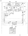
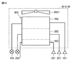
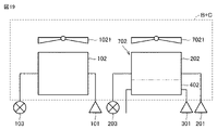
- FIG. 1 is a diagram showing the configuration of a binary refrigeration cycle device 51 according to Embodiment 1. As shown in FIG. Based on FIG. 1, the circuit configuration and operation of the binary refrigeration cycle device 51 will be described.
- the binary refrigeration cycle device 51 includes a low-order refrigerant circuit 300 , a first high-order refrigerant circuit 100 , a second high-order refrigerant circuit 200 , and a control device 30 .
- the first high-level refrigerant circuit 100 and the second high-level refrigerant circuit 200 are arranged in the outdoor unit 1 .
- the low-concentration refrigerant circuit 300 is arranged across the outdoor unit 1 and the indoor unit 2 by the extension pipe 15 .
- the control device 30 is arranged in the outdoor unit 1 or the indoor unit 2 .
- the outdoor unit 1 is provided with a temperature sensor 20 that detects the outside air temperature.
- the control device 30 may be arranged at a location other than the outdoor unit 1 and the indoor unit 2 .
- the control device 30 may wirelessly communicate with a remote controller operated by a user.
- a first refrigerant is sealed in the first high-level refrigerant circuit 100 .
- a second refrigerant is sealed in the second high-level refrigerant circuit 200 .
- a third refrigerant is sealed in the low-concentration refrigerant circuit 300 .
- the outdoor unit 1 includes a first cascade condenser 104 for exchanging heat between the first refrigerant of the first high-order refrigerant circuit 100 and the third refrigerant of the low-order refrigerant circuit 300, and a second high-order refrigerant circuit.
- a second cascade condenser 204 is provided for exchanging heat between the second refrigerant of 200 and the third refrigerant of the lower refrigerant circuit 300 .
- the first cascade capacitor 104 may be included in the first high-order refrigerant circuit 100 or may be included in the low-order refrigerant circuit 300 .
- the second cascade condenser 204 may be included in the second high-order refrigerant circuit 200 or may be included in the low-order refrigerant circuit 300 .
- the first high-level refrigerant circuit 100 includes a first compressor 101 , a first heat exchanger 102 and a first expansion valve 103 .
- the first compressor 101, the first heat exchanger 102, and the first expansion valve 103 are connected by a refrigerant pipe through which the first refrigerant flows.
- the first heat exchanger 102 is provided with a first fan 1021 that facilitates heat exchange between the outside air and the first refrigerant.
- the first high-level refrigerant circuit 100 is configured such that the first refrigerant circulates through the first compressor 101, the first heat exchanger 102, the first expansion valve 103, the first cascade condenser 104, and the first compressor 101 in this order. configured to Therefore, the first heat exchanger 102 functions as a condenser.
- a microcomputer that operates in response to a command from the control device 30 is installed in the first high-level refrigerant circuit 100 . When the control device 30 activates the first high-order refrigerant circuit 100, the first high-order refrigeration cycle is started.
- the second high-level refrigerant circuit 200 includes a second compressor 201 , a second heat exchanger 202 and a second expansion valve 203 .
- the second compressor 201, the second heat exchanger 202, and the second expansion valve 203 are connected by a refrigerant pipe through which the second refrigerant flows.
- the second heat exchanger 202 is provided with a second fan 2021 that promotes heat exchange between the outside air and the second refrigerant.
- the second high-level refrigerant circuit 200 is configured such that the second refrigerant circulates through the second compressor 201, the second heat exchanger 202, the second expansion valve 203, the second cascade condenser 204, and the second compressor 201 in that order. configured to Therefore, the second heat exchanger 202 functions as a condenser.
- the second high-level refrigerant circuit 200 is equipped with a microcomputer that operates in response to commands from the control device 30 .
- the control device 30 activates the second high-order refrigerant circuit 200 to activate the second high-order refrigeration cycle.
- first high-level refrigerant circuit 100 and second high-level refrigerant circuit 200 are configured to have different maximum cooling capacities.
- the second compressor 201, the second heat exchanger 202, the second expansion circuit 201, the second heat exchanger 202, and the second expansion circuit 201 are arranged so that the maximum cooling capacity of the second high-order refrigerant circuit 200 is lower than the maximum cooling capacity of the first high-order refrigerant circuit 100.
- At least one component of the valve 203 and the second cascade condenser 204 is connected to the first compressor 101 , the first heat exchanger 102 , the first expansion valve 103 and the first cascade condenser 104 of the first higher order refrigerant circuit 100 .
- the low energy refrigerant circuit 300 includes a third compressor 301 , a third heat exchanger 302 , a third expansion valve 303 and a liquid receiver 304 .
- the third heat exchanger 302 and the third expansion valve 303 are arranged in the indoor unit 2 .
- the liquid receiver 304 is arranged in the outdoor unit 1 .
- the third compressor 301, the third heat exchanger 302, the third expansion valve 303, and the receiver 304 are connected by refrigerant pipes through which the third refrigerant flows.
- the third heat exchanger 302 is provided with a third fan 3021 that promotes heat exchange between the air inside the storage and the third refrigerant.
- the third refrigerant is a third compressor 301, a first cascade condenser 104, a second cascade condenser 204, a liquid receiver 304, a third expansion valve 303, a third heat exchanger 302, and a third refrigerant.
- the three compressors 301 are configured to circulate in order. Therefore, the third heat exchanger 302 functions as an evaporator that cools the inside of the refrigerator.
- a microcomputer that operates in response to commands from the control device 30 is installed in the low-concentration refrigerant circuit 300 . When the control device 30 activates the low-concentration refrigerant circuit 300, the low-concentration refrigeration cycle is activated.
- a pressure sensor 10 is provided in the refrigerant pipe located on the discharge side of the third compressor 301 .
- the pressure sensor 10 may be provided at any position in the section from the discharge port of the third compressor 301 to the inlet of the first cascade condenser 104 .
- the third compressor 301 circulates the third refrigerant in the low-concentration refrigerant circuit 300 by increasing the pressure of the third refrigerant.
- the third compressor 301 changes its operating capacity according to the situation by controlling a motor (not shown) inside the third compressor 301 with an inverter.
- the third compressor 301 controls the frequency of the third compressor 301 so that the temperature of the third refrigerant reaches the target outlet temperature set by the control device 30 .
- the third expansion valve 303 adjusts the flow rate of the third refrigerant.
- Third expansion valve 303 is, for example, an electronic expansion valve or a capillary.
- the electronic expansion valve has a function of efficiently controlling the flow rate of the third refrigerant by adjusting the throttle opening.
- the liquid receiver 304 stores high-pressure liquid refrigerant.
- the liquid receiver 304 is arranged between the second cascade condenser 204 and the third expansion valve 303 in the low-concentration refrigerant circuit 300 .
- the liquid receiver 304 is arranged downstream of the first cascade condenser 104 and the second cascade condenser 204 and upstream of the third expansion valve 303 .
- the liquid receiver 304 and the second cascade condenser 204 are connected by the first refrigerant pipe 16 .
- the liquid receiver 304 and the third expansion valve 303 are connected by the second refrigerant pipe 17 and the extension pipe 15 .
- the first refrigerant pipe 16 is connected to the upper portion of the liquid receiver 304 .
- the second refrigerant pipe 17 is connected to the lower portion of the liquid receiver 304 .
- a return refrigerant pipe 18 is further connected to the upper portion of the liquid receiver 304 .
- the return refrigerant pipe 18 connects the refrigerant pipe positioned between the first cascade condenser 104 and the second cascade condenser 204 and the liquid receiver 304 .
- the return refrigerant pipe 18 is provided with a check valve 305 that prevents the first refrigerant from flowing into the liquid receiver 304 from the first cascade condenser 104 or the second cascade condenser 204 through the return refrigerant pipe 18 .
- the control device 30 is equipped with a processor 31 and a memory 32 .
- Processor 31 executes an operating system and application programs stored in memory 32 .
- the processor 31 refers to various data stored in the memory 32 when executing the application program.
- Processor 31 collects data indicating operating conditions from first high-order refrigerant circuit 100 , second high-order refrigerant circuit 200 , and low-order refrigerant circuit 300 according to an application program stored in memory 32 .
- the processor 31 acquires the pressure of the third refrigerant based on the detection value of the pressure sensor 10.
- the processor 31 acquires the outside air temperature based on the detection value of the temperature sensor 20 .
- Processor 31 controls first high-order refrigerant circuit 100 , second high-order refrigerant circuit 200 , and low-order refrigerant circuit 300 according to application programs stored in memory 32 .
- the control device 30 can switch the operation mode between the cooling operation mode and the stop operation mode.
- the cooling operation mode is an operation mode for cooling the inside of the refrigerator where the third heat exchanger 302 is arranged.
- the low temperature refrigerant circuit 300 and the second high temperature refrigerant circuit 200 operate.
- the first high-order refrigerant circuit 100 may further operate depending on the operating conditions of the low-order refrigerant circuit 300 and the second high-order refrigerant circuit 200 .
- the stop operation mode is an operation mode used when the inside of the refrigerator is not cooled. In the stop operation mode, the operation of the low-concentration refrigerant circuit 300 is stopped. In the stop operation mode, the second high-voltage refrigerant circuit 200 operates to prevent the pressure in the low-voltage refrigerant circuit 300 from abnormally increasing. In the stop operation mode, the first high-voltage refrigerant circuit 100 may be operated further.
- the control device 30 can independently control the first high-order refrigerant circuit 100, the second high-order refrigerant circuit 200, and the low-order refrigerant circuit 300 in the cooling operation mode.
- the control device 30 can select either the low-capacity operation mode or the high-capacity operation mode in the cooling operation mode.
- the low capacity operation mode is a mode in which the first high-level refrigerant circuit 100 is stopped and the low-level refrigerant circuit 300 and the second high-level refrigerant circuit 200 are operated.
- the high-capacity operation mode is a mode in which the first high-order refrigerant circuit 100, the second high-order refrigerant circuit 200, and the low-order refrigerant circuit 300 are operated.
- the control device 30 is configured to be able to select an operation mode in which only the low-level refrigerant circuit 300 is operated among the first high-level refrigerant circuit 100, the second high-level refrigerant circuit 200, and the low-level refrigerant circuit 300. good too.
- first high-level refrigerant circuit 100 ⁇ Operation of first high-order refrigerant circuit 100 and second high-order refrigerant circuit 200> The operation of the first high-level refrigerant circuit 100 will be described.
- the high-temperature and high-pressure gaseous first refrigerant discharged from the first compressor 101 flows into the first heat exchanger 102 functioning as a condenser.
- the first refrigerant changes from a gas state refrigerant to a liquid state refrigerant in the first heat exchanger 102 .
- the first refrigerant that has flowed out of the first heat exchanger 102 flows into the first expansion valve 103 and is decompressed. As a result, the liquid state first refrigerant changes to a low-pressure two-phase refrigerant.
- a low-pressure two-phase refrigerant flows from the first expansion valve 103 into the first cascade condenser 104 .
- the first refrigerant flowing into the first cascade condenser 104 takes heat from the third refrigerant flowing through the low-concentration refrigerant circuit 300 .
- the third refrigerant is condensed and the first refrigerant is gasified.
- the gasified first refrigerant is sucked into the first compressor 101 .
- the operation of the second high-level refrigerant circuit 200 is the same as the operation of the first high-level refrigerant circuit 100, so the description thereof will not be repeated here.
- the difference between the first high-order refrigerant circuit 100 and the second high-order refrigerant circuit 200 is the maximum cooling capacity.
- the first high-order refrigerant circuit 100 and the second high-order refrigerant circuit 200 have different capacities to condense the third refrigerant flowing through the low-order refrigerant circuit 300 .
- the second higher order refrigerant circuit 200 is designed to be less capable of condensing the third refrigerant than the first higher order refrigerant circuit 100 .
- ⁇ Operation of low-concentration refrigerant circuit 300 The operation of the low-concentration refrigerant circuit 300 will be described.
- the high-temperature and high-pressure gaseous third refrigerant discharged from the third compressor 301 flows to the first cascade condenser 104 and the second cascade condenser 204 .
- the first cascade condenser 104 functions as a condenser for the third refrigerant.
- the second cascade condenser 204 functions as a condenser for the third refrigerant.
- the third refrigerant thereby changes from a gas state refrigerant to a liquid state refrigerant.
- the third refrigerant that has flowed out of the second cascade condenser 204 flows into the liquid receiver 304 .
- the liquid state third refrigerant accumulated in the liquid receiver 304 is pushed out to the second refrigerant pipe 17 by the gas pressure in the liquid receiver 304 .
- the third refrigerant flowing into the second refrigerant pipe 17 goes to the third expansion valve 303 via the extension pipe 15 .
- the pressure of the third refrigerant that has flowed into the third expansion valve 303 is reduced by the third expansion valve 303 .
- the liquid third refrigerant changes to a low-pressure two-phase refrigerant.
- Low pressure two-phase refrigerant moves from the third expansion valve 303 to the third heat exchanger 302 .
- the third heat exchanger 302 functions as an evaporator.
- the third refrigerant that has flowed into the third heat exchanger 302 exchanges heat with the air inside the refrigerator. This cools the inside of the refrigerator.
- the third refrigerant gasified inside the third heat exchanger 302 is sucked into the third compressor 301 .
- the control device 30 adjusts the frequency of the third compressor 301 and the rotation speed of the third fan 3021 based on various parameters.
- Parameters can include, for example, intake temperature, discharge temperature, heat exchanger temperature, air intake temperature, and humidity.
- the control device 30 can acquire these parameters using the values of sensors arranged in the low-concentration refrigerant circuit 300 .
- a temperature sensor may be provided at the discharge portion of the third compressor 301 to detect the discharge temperature of the third refrigerant.
- the control device 30 sends a control signal to the low-concentration refrigerant circuit 300 based on the temperature difference between the detection result of the temperature sensor and the preset discharge temperature of the third compressor 301 .
- the low-concentration refrigerant circuit 300 adjusts the rotation speed of the third compressor 301, the rotation speed of the third fan 3021, or the opening degree of the third expansion valve 303 based on the control signal. By this adjustment, the control device 30 can control the temperature of various devices provided in the low-concentration refrigerant circuit 300 so as not to rise above the heat-resistant temperature.
- the condensation temperature may be estimated from the detected value of the pressure sensor 10 .
- FIG. 2 is a diagram showing the arrangement relationship between the liquid receiver 304 and the first cascade capacitor 104 and the second cascade capacitor 204.
- the liquid receiver 304 is arranged at a position lower than the first cascade capacitor 104 and the second cascade capacitor 204 in the vertical direction. Therefore, even when the low-concentration refrigerant circuit 300 is not activated, the third refrigerant cooled and liquefied by the first cascade condenser 104 or the second cascade condenser 204 falls to the liquid receiver 304 due to gravity. This is especially effective in the stop operation mode that controls when the low-order refrigerating cycle is not activated. The operation of the stop operation mode will be described in detail below with reference to FIGS. 1 and 2.
- FIG. 1 The operation of the stop operation mode will be described in detail below with reference to FIGS. 1 and 2.
- the control device 30 activates the high-order refrigeration cycle when the low-order refrigeration cycle is stopped. Such an operation mode is called a stop operation mode. By operating the binary refrigerating cycle device 51 in the stop operation mode, the control device 30 prevents the pressure increase due to the temperature increase of the third refrigerant staying in the low temperature refrigerant circuit 300 .
- the control device 30 activates the high-level refrigeration cycle when the outside air temperature becomes equal to or higher than the reference temperature while the low-level refrigeration cycle is stopped.
- the reference temperature is, for example, -5°C.
- the pressure in the low-level refrigerant circuit 300 is equalized, and eventually the pressure becomes the pressure corresponding to the outside air temperature.
- the average density of the third refrigerant is small. Therefore, the pressure decreases according to Boyle-Charles' law (P ⁇ T).
- P ⁇ T Boyle-Charles' law
- the third refrigerant in the low-level refrigerant circuit 300 evaporates by absorbing heat from the outside air. This increases the pressure in the low-concentration refrigerant circuit 300 .
- the pressure depends on the relationship between pressure and temperature based on the type of refrigerant. becomes. For example, if the refrigerant is CO2 (carbon dioxide) and the temperature is 20° C., the pressure is 5.6 MPaG.
- the third refrigerant can be forcibly cooled by activating the high-level refrigeration cycle when the low-level refrigeration cycle is stopped. As a result, the temperature of the third coolant is lower than the outside air. Then, the pressure of the third refrigerant in the low-concentration refrigerant circuit 300 decreases.
- the high-level refrigeration cycle activated by the control device 30 in the stop operation mode is the second high-level refrigeration cycle.
- the control device 30 controls the frequency of the second compressor 201 of the second high-order refrigerating cycle, the rotation speed of the second fan 2021, and the degree of opening of the second expansion valve 203 . If the abnormal rise in pressure in the low-order refrigerant circuit 300 cannot be suppressed only by starting the second high-order refrigeration cycle, the control device 30 starts the first high-order refrigeration cycle with higher condensing capacity.
- the second cascade condenser 204 existing between the second high-order refrigerant circuit 200 and the low-order refrigerant circuit 300 becomes a condenser for the third refrigerant.
- the third refrigerant in the second cascade condenser 204 is condensed.
- the third refrigerant condensed by the second cascade condenser 204 is liquefied.
- the liquefied third refrigerant passes through the first refrigerant pipe 16 and drips into the liquid receiver 304 .
- the volume of the gas phase decreases.
- the gaseous third refrigerant which is not easily affected by gravity, is sucked up to the upstream side of the second cascade condenser 204 via the return refrigerant pipe 18 .
- the return refrigerant pipe 18 is connected to the upper part of the liquid receiver 304, so that the third refrigerant existing above the liquid receiver 304 can be naturally sucked.
- the check valve 305 prevents the third refrigerant, which should flow from the first cascade condenser 104 to the second cascade condenser 204 , from flowing into the liquid receiver 304 via the return refrigerant pipe 18 .
- the third refrigerant in the cooling operation mode, it is possible to prevent the third refrigerant from bypassing the second cascade condenser 204 and flowing into the liquid receiver 304 .
- the vaporous third refrigerant sucked up to the upstream side of the second cascade condenser 204 is cooled by the second cascade condenser 204 and liquefied.
- the liquefied third refrigerant drips into the liquid receiver 304 .
- the low-concentration refrigeration cycle is not activated, but the third refrigerant flows through the low-concentration refrigerant circuit 300 due to such natural circulation.
- the pressure rise in the low-concentration refrigerant circuit 300 can be effectively suppressed. Further, only the gas to be condensed can be allowed to flow through the return refrigerant pipe 18 in order to suppress the pressure from rising. Furthermore, by providing the second cascade condenser 204 , the liquid third refrigerant can be stored in the liquid receiver 304 without directly cooling the liquid receiver 304 .
- Both the first cascade condenser 104 and the second cascade condenser 204 function as condensers for the third refrigerant and cool the third refrigerant before it flows into the liquid receiver 304 . Therefore, it is not necessary to provide the liquid receiver 304 with a cooling function.
- the first cascade capacitor 104 and the second cascade capacitor 204 exhibit a cooling function even in the cooling operation mode. Therefore, the configuration of the liquid receiver 304 can be simplified compared to a configuration in which the liquid receiver 304 is provided with the function of cooling the third refrigerant during the cooling operation. This is because the liquid receiver 304 requires an evaporator when the third refrigerant is cooled in the liquid receiver 304 .
- the volume of the liquid receiver 304 must be reduced. Further, when a heat transfer tube is provided around the container of the liquid receiver 304, there arises a problem that the contact portion is easily deteriorated due to thermal fatigue, and furthermore, the container has a complicated structure. According to this embodiment, the configuration of the liquid receiver 304 can be simplified, and the manufacturing cost can be reduced.
- the binary refrigeration cycle device 51 activates at least the second high-order refrigeration cycle even when the low-order refrigeration cycle is stopped, and the second cascade condenser 204 supplies the low-order refrigerant circuit 300 with Cool the remaining third refrigerant.
- the third refrigerant in the low-concentration refrigerant circuit 300 it is possible to effectively suppress the pressure increase due to the temperature increase of the third refrigerant.
- This eliminates the need to set the design pressures of various devices such as the third compressor 301, the third heat exchanger 302, the third expansion valve 303, the liquid receiver 304, and the refrigerant pipes to high values. As a result, it is possible to reduce the cost of the equipment that constitutes the low-concentration refrigerant circuit 300 .
- FIG. 3 is a diagram showing a comparative example of configurations of the first high-order refrigerant circuit 100, the second high-order refrigerant circuit 200, and the low-order refrigerant circuit 300.
- first high-level refrigerant circuit 100 and second high-level refrigerant circuit 200 are configured to have different maximum cooling capacities. More specifically, the cooling capacity of the second high-order refrigerant circuit 200 is configured to be lower than the cooling capacity of the first high-order refrigerant circuit 100 .
- numerical values relating to the capacity of the low-concentration refrigerant circuit 300 are omitted.
- FIG. 3 shows an example in which the rated capacity of the first high-level refrigerant circuit 100 is 41 kW and the rated capacity of the second high-level refrigerant circuit 200 is 10 kW.
- the high-side capacity (cooling capacity) is calculated as 51 kW by adding 41 kW and 10 kW.
- the ratio of the rated capacity of the second higher-order refrigerant circuit 200 to 51 kW is approximately 20% as shown in FIG.
- the maximum cooling capacity of the second high-level refrigerant circuit 200 should be less than 50% of the maximum cooling capacity of the first high-level refrigerant circuit 100 and the second high-level refrigerant circuit 200 . That is, the upper limit of the cooling capacity of the second high-order refrigerant circuit 200 may be less than 50% of the upper limit of the cooling capacity of the first high-order refrigerant circuit 100 and the second high-order refrigerant circuit 200 .
- the upper limit of the cooling capacity of the second high-order refrigerant circuit 200 is preferably 35% or less of the upper limit of the cooling capacity of the first high-order refrigerant circuit 100 and the second high-order refrigerant circuit 200 .
- the upper limit of the cooling capacity of the second high-order refrigerant circuit 200 is more preferably 20% or less of the upper limit of the cooling capacity of the first high-order refrigerant circuit 100 and the second high-order refrigerant circuit 200 .
- the second compressor 201 of the second high-level refrigerant circuit 200, the second heat At least one component of the exchanger 202 , the second expansion valve 203 and the second cascade condenser 204 is connected to the first compressor 101 , the first heat exchanger 102 and the first expansion of the first high-level refrigerant circuit 100 .
- the valve 103 and first cascade capacitor 104 may be configured with components having a smaller capacity than the corresponding components.
- the size of the compressor has the greatest impact on the cost and cooling capacity of the refrigerant circuit. Therefore, by configuring the second compressor 201 with a compact compressor having a smaller capacity than the first compressor 101, the cooling capacity between the first high-level refrigerant circuit 100 and the second high-level refrigerant circuit 200 is increased. It is desirable to have a difference. By downsizing the second compressor 201, the cost of the second high-order refrigerant circuit 200 can also be reduced. By miniaturizing the second compressor 201, the material costs required for the second compressor 201 can be reduced. Moreover, since the volume of the second compressor 201 is reduced, the amount of refrigerant required for the second high-order refrigerant circuit 200 can be reduced.
- second compressor 201 is composed of a compact compressor having a smaller capacity than first compressor 101 .
- the refrigerant capacity of the second high-order refrigerant circuit 200 is smaller than that of the first high-order refrigerant circuit 100 .
- the lower limit capacity of the first high-level refrigerant circuit 100 is 10 kW
- the second high-level refrigerant circuit 100 has a lower limit capacity of 10 kW
- the lower limit capability of circuit 200 is 2.5 kW.
- the lower limit capacity is 25% of the rated capacity from the frequency range of the compressor.
- the high-level refrigerating cycle is composed of a first high-level refrigerating cycle and a second high-level refrigerating cycle, and by providing a difference in the capacity of each cycle, the operating range is expanded. ing. Differentiating the rated capacity between the first high-order refrigerant circuit 100 and the second high-order refrigerant circuit 200 is effective both in the cooling operation mode and the stop operation mode.
- control device 30 selects between the low-capacity operation mode and the high-capacity operation mode according to environmental conditions such as the set temperature in the refrigerator where the third heat exchanger 302 is arranged and the outside air temperature. Select one of the cooling operation modes.
- the control device 30 activates the second high-level refrigerant circuit 200 having a lower cooling capacity than the first high-level refrigerant circuit 100 in the stop operation mode.
- the cooling load is usually smaller than in the cooling mode of operation. This is because the purpose of the cooling operation mode is to cool the inside of the refrigerator, while the purpose of the stop operation mode is to suppress an abnormal increase in pressure in the low-concentration refrigerant circuit 300 .
- the stop operation mode in which the cooling load is small if the higher capacity refrigerating cycle is started, the compressor on the higher refrigerating cycle side is frequently started and stopped.
- the high-level refrigeration cycle is composed of a single refrigeration cycle.
- the rated capacity of a single high-order refrigeration cycle is 51 kW.
- the value of 51 kW is the sum of the rated capacity of the first high-level refrigerant circuit 100 and the rated capacity of the second high-level refrigerant circuit 200 shown in FIG.
- the lower limit capacity is 13 kW.
- a value of 13 kW may be too large for the cooling capacity required for the shutdown mode of operation.
- the capacity of the high-order refrigeration cycle is too large for the required cooling capacity, so the suction pressure of the compressor of the high-order refrigeration cycle drops.
- the compressor will repeat starting and stopping, which may reduce the reliability of the binary refrigeration cycle apparatus.
- power consumption may increase.
- two cycles form a high-level refrigeration cycle.
- the operating range of 2.5 kW to 51 kW is ensured by dividing the capacity of the high-level refrigeration cycle into two.
- the operating capacity of 2.5 kW which is the lower limit, can be realized by the second high-voltage refrigerant circuit 200 .
- the upper limit of the operating capacity of 51 kW can be realized by the first high-order refrigerant circuit 100 and the second high-order refrigerant circuit 200 .
- the second high-level refrigerant circuit 200 is activated. This prevents the compressor of the high-level refrigeration cycle from repeatedly starting and stopping in the stop operation mode.
- the high-level refrigeration cycle side can demonstrate appropriate capacity according to needs, so the compressor of the high-level refrigeration cycle is prevented from repeatedly starting and stopping. be done. That is, in the present embodiment, the high-level refrigerating cycle is composed of a first high-level refrigerating cycle and a second high-level refrigerating cycle, and by providing a difference in the capacity of each cycle, the operating range is expanded. ing. It should be noted that the required cooling capacity in the stop operation mode is assumed to be approximately 1 kW to 4 kW, for example.
- the present embodiment it is possible to prevent the first compressor 101 and the second compressor 201 on the high-level refrigerating cycle side from repeatedly starting and stopping. Therefore, energy saving can be improved. In particular, it is important that the compressor does not repeatedly start and stop because starting loss occurs when the compressor starts.
- ⁇ Refrigerant type> Various combinations of refrigerant types to be sealed in the low-order refrigerant circuit 300, the first high-order refrigerant circuit 100, and the second high-order refrigerant circuit 200 can be determined.
- the refrigerant in each refrigerant circuit may be the same refrigerant. Further, the same refrigerant is sealed in the first high-order refrigerant circuit 100 and the second high-order refrigerant circuit 200, and is sealed in the first high-order refrigerant circuit 100 and the second high-order refrigerant circuit 200 in the low-order refrigerant circuit 300.
- a refrigerant different from the refrigerant may be used.
- refrigerants differ in theoretical performance, GWP (Global-warming potential), combustibility, toxicity, etc., depending on the type.
- refrigerants such as R290 and R32 have high theoretical performance, but high combustibility, toxicity, and global-warming potential (GWP). Therefore, considering flammability, toxicity, and GWP, it should be avoided to enclose a large amount of these refrigerants in the refrigerant circuit.
- R1234yf and the like have a low ozone depletion potential and a low global warming potential, and are considered to be extremely environmentally friendly refrigerants.
- Natural refrigerants such as CO2 have the advantage of significantly reducing the total GWP of equipment.
- incombustible gas such as CO2 is desirably used in the indoor unit in consideration of possible refrigerant leakage.
- the type of refrigerant is determined whether the refrigerant circuit to be enclosed is the low-level refrigerant circuit 300 passing through the indoor unit 2, or the first high-level refrigerant circuit 100 or the second high-level refrigerant circuit 200 used in the outdoor unit 1. It is conceivable to select from the viewpoint of whether Also, the type of refrigerant can be selected from the viewpoint of whether the refrigerant circuit to be enclosed is the first high-level refrigerant circuit 100 with high cooling performance or the second high-level refrigerant circuit 200 with low cooling performance. Conceivable. In the present embodiment, the refrigerant capacity of the second high-order refrigerant circuit 200 is smaller than that of the first high-order refrigerant circuit 100 .
- FIG. 3 shows an example in which different refrigerants are sealed in the first high-order refrigerant circuit 100, the second high-order refrigerant circuit 200, and the low-order refrigerant circuit 300, respectively.
- an appropriate refrigerant is selected in consideration of the characteristics of the refrigerant and the characteristics of the refrigerant circuit that encloses the refrigerant.
- R1234yf which is friendly to the global environment, is enclosed in the high-capacity first high-level refrigerant circuit 100, and R32, which has high theoretical performance, is enclosed in the low-capacity second high-level refrigerant circuit 200, respectively. That is, the first refrigerant is R1234yf and the second refrigerant is R32.
- the low-concentration refrigerant circuit 300 passing through the indoor unit 2 is filled with CO2, which is a non-combustible gas. That is, the first refrigerant is CO2.
- R290 or R714 (ammonia) may be sealed in the second high-concentration refrigerant circuit 200 instead of R32.
- the low-concentration refrigerant circuit 300 may contain hfc1132A instead of CO2.
- Refrigerants such as R290 and R32 which have high theoretical performance but are concerned about being filled in large amounts in consideration of combustibility, toxicity, and high GWP, have a refrigerant capacity larger than that of the first high-level refrigerant circuit 100. It is enclosed in a small second high-order refrigerant circuit 200 . In this way, for the second high-order refrigerant circuit 200 having a small capacity, a refrigerant having higher theoretical performance or higher performance in practical use than the refrigerant to be enclosed in the first high-order refrigerant circuit 100 and the low-order refrigerant circuit 300 By enclosing , the COP (Coefficient Of Performance) of the system can be improved.
- R1234yf which is extremely environmentally friendly refrigerant
- the refrigerant in the second high-level refrigerant circuit 200 is R1234yf. It is desirable to change to R290, which has a higher theoretical performance.
- a refrigerant such as R32 that has high theoretical performance but does not have high combustibility, toxicity, and GWP is used in the second high-order refrigerant circuit 200 that uses a small amount of refrigerant. .
- a refrigerant such as R1234yf which is said to be friendly to the global environment, is used in the first high-level refrigerant circuit 100 that uses a large amount of refrigerant.
- FIG. 3 shows an example of enclosing CO2 in the low-concentration refrigerant circuit 300 . Since the third refrigerant in the low-concentration refrigerant circuit 300 flows through the indoor unit 2 , it is preferable to use CO 2 , which is nonflammable and high-pressure refrigerant, as the third refrigerant in the low-concentration refrigerant circuit 300 . Since CO2 is a natural refrigerant, it can significantly reduce the total GWP of equipment.
- the dual refrigerating cycle device 51 realizes two types of refrigerating cycles, a low-level refrigerating cycle and a high-level refrigerating cycle. Therefore, the condensation pressure on the low temperature side can be reduced in the high temperature refrigeration cycle. Therefore, even if CO2, which is a high-pressure refrigerant, is used in the low-concentration refrigerant circuit 300, the low-concentration refrigerant circuit 300 can be applied with refrigerant pipes and element devices with low pressure resistance. For this reason, it is possible to use element devices that could not be used conventionally in the low-concentration refrigerant circuit 300 .
- the liquid receiver 304 only needs to be pressure resistant to Freon (R410A).
- the portion of the first cascade capacitor 104 and the second cascade capacitor 204 through which the low-concentration refrigerant circuit 300 passes should also have pressure resistance against Freon. Since the low-concentration refrigerant circuit 300 is provided with a large number of element devices such as refrigerant pipes, it is possible to reduce costs by reducing the required pressure resistance.
- a single-stage refrigeration cycle device or a two-stage refrigeration cycle device requires high pressure resistance, so there is no choice but to use expensive equipment with high pressure resistance.
- the dual refrigerating cycle is adopted, such a need is eliminated.
- the binary refrigerating cycle device 51 requires a lower pressure on the side of condensing CO2 than when CO2 is applied to a single-stage refrigerating cycle device or a two-stage refrigerating cycle device. The lower the pressure, the smaller the density of the refrigerant.
- the condenser volume is the same, the amount of CO2 required as a refrigerant can be reduced.
- CO2 is applied to the low-level refrigerant circuit 300
- R290 is applied to the first high-level refrigerant circuit 100 and the second high-level refrigerant circuit 200, respectively.
- CO2 is applied to the low-level refrigerant circuit 300
- R1234yf is applied to the first high-level refrigerant circuit 100 and the second high-level refrigerant circuit 200, respectively.
- FIG. 4 is a diagram showing Modification 1 of the binary refrigeration cycle device 51 related to Embodiment 1.
- the return refrigerant pipe 18 extending from the liquid receiver 304 is connected between the first cascade condenser 104 and the third compressor 301 . Therefore, the gasified third refrigerant flows from the liquid receiver 304 into the first cascade condenser 104 .
- the third refrigerant flowing into the first cascade condenser 104 is cooled by the first cascade condenser 104 and then flows into the second cascade condenser 204 . Therefore, in comparison with the configuration shown in FIG. 1, in Modification 1, a further cooling effect for the third refrigerant can be obtained.
- the position where the return refrigerant pipe 18 extending from the liquid receiver 304 is connected may be any position from the discharge portion of the third compressor 301 to the inlet portion of the first cascade condenser 104 . More preferably, the return refrigerant pipe 18 extending from the liquid receiver 304 is connected to the discharge portion of the third compressor 301 . This is because the pressure of the third refrigerant is highest at the discharge portion of the third compressor 301 .
- FIG. 5 is a diagram showing a fifth heat exchanger 502 in which the first heat exchanger 102 and the second heat exchanger 202 are integrated.
- the fifth heat exchanger 502 corresponds to an integrated structure of the components indicated by symbol A in FIG. 1 .
- the fifth heat exchanger 502 is divided into the first high-level refrigerant circuit 100 in which the first refrigerant flows and the second high-level refrigerant circuit 200 in which the second refrigerant flows, and the first heat exchanger 102 and the second heat exchanger 502 are separated. It has a configuration in which it is integrated with the exchanger 202 .
- a fifth fan 5021 is provided in the fifth heat exchanger 502 . However, a plurality of fans may be provided for the fifth heat exchanger 502 .
- the space for arranging equipment can be effectively utilized. Further, by integrating the first heat exchanger 102 and the second heat exchanger 202, the cost can be reduced. Note that the integrated fifth heat exchanger 502 may be applied to Modification 1 shown in FIG.
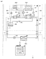
- FIG. 6 is a diagram showing an example in which an uninterruptible power supply 205 is provided in the binary refrigerating cycle device 51 according to Embodiment 1.
- FIG. 6 As shown in FIG. 6 , the second high-voltage refrigerant circuit 200 is connected to an uninterruptible power supply 205 .
- control device 30 may be connected to the uninterruptible power supply 205.
- the uninterruptible power supply 205 and another uninterruptible power supply may be connected to the control device 30 .
- the control device 30 can operate in the stop operation mode using the second high temperature refrigerant circuit 200 .
- it is possible to prevent the pressure in the low-concentration refrigerant circuit 300 from abnormally increasing during a power failure. Therefore, it is not necessary to suppress the pressure rise by extracting the third refrigerant from the low-concentration refrigerant circuit 300 to the outside at the time of power failure. According to this configuration, it is possible to suppress the pressure rise accompanying the temperature rise of the low-order refrigeration cycle without lowering the reliability.
- An uninterruptible power supply 205 may be provided in the first high-voltage refrigerant circuit 100 as well. However, it is preferable to preferentially provide the uninterruptible power supply 205 for the second high-order refrigerant circuit 200 of the first high-order refrigerant circuit 100 and the second high-order refrigerant circuit 200 . This is because the second high-level refrigerant circuit 200 is activated in the stop operation mode.
- the capacity of the second high-order refrigerant circuit 200 is smaller than that of the first high-order refrigerant circuit 100, the power supply capacity required for the uninterruptible power supply 205 can be small. Therefore, it is more economical to provide the uninterruptible power supply 205 in the second high-order refrigerant circuit 200 than in the first high-order refrigerant circuit 100 . In addition, a small capacity uninterruptible power supply 205 can be used for the second high-level refrigerant circuit 200 .
- FIG. 7 is a diagram showing an example in which an uninterruptible power supply 205 is provided in the binary refrigeration cycle apparatus 51 of Modification 1.
- FIG. 7 the uninterruptible power supply 205 can be applied to Modification 1 as well as the configuration shown in FIG.
- the uninterruptible power supply 205 may be applied to the binary refrigerating cycle device 51 employing the integrated fifth heat exchanger 502 in the same manner as the configuration shown in FIG.
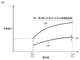
- FIG. 8 is a graph 1 showing the relationship between the frequency range and cooling capacity of the first high-order refrigeration cycle and the relationship between the frequency range and cooling capacity of the second high-order refrigeration cycle.
- L1a indicates the frequency range of the first compressor 101 that constitutes the first high-order refrigeration cycle.
- L2a indicates the frequency range of the second compressor 201 that constitutes the second high-order refrigeration cycle.
- the maximum cooling capacity of the first high-order refrigeration cycle is higher than that of the second high-order refrigeration cycle.
- the second high-order refrigeration cycle has a lower minimum cooling capacity than the first high-order refrigeration cycle.
- the lower limit frequency of the first higher refrigeration cycle is f1min
- the upper limit frequency of the first higher refrigeration cycle is f1max.
- the lower limit frequency of the second higher refrigeration cycle is f2min
- the upper limit frequency of the second higher refrigeration cycle is f2max.
- the cooling capacity that can be output at the upper limit frequency f2max of the second higher refrigeration cycle is designed to be greater than the cooling capacity that can be output at the lower limit frequency f1min of the first higher refrigeration cycle.
- a range Ca is generated in which the cooling capacity of the first high-order refrigeration cycle and the cooling capacity of the second high-order refrigeration cycle overlap.
- the cooling capacity range of the first high-order refrigeration cycle is designed to be 10 kW to 40 kW
- the cooling capacity range of the second high-order refrigeration cycle is designed to be 2 kW to 10 kW.
- the cooling capacities of both high-order refrigeration cycles are divided into lower capacities and upper capacities with 10 kW as the boundary.
- the minimum cooling capacity when both high-level refrigeration cycles are activated is 12 kW.
- the required capacity of the low-order refrigeration cycle is smaller than the cooling capacity of the high-order refrigeration cycle, the first high-order refrigeration cycle is stopped to reduce the cooling capacity, and only the second high-order refrigeration cycle is used as the high-order refrigeration cycle.
- FIG. 9 is graph 2 showing the relationship between the frequency range and cooling capacity of the first high-order refrigeration cycle and the relationship between the frequency range and cooling capacity of the second high-order refrigeration cycle.
- the lower limit frequency f1min of the first higher refrigerating cycle and the lower limit frequency f2min of the second higher refrigerating cycle match, and the upper limit frequency f1max of the first higher refrigerating cycle and the second higher refrigerating cycle It matches the upper limit frequency f2max of the high-order refrigerating cycle.
- the cooling capacity of the first high-order refrigeration cycle and the cooling capacity of the second high-order refrigeration cycle are designed to overlap with each other. there is Therefore, similar to the example shown in FIG. 8, the above-described problems caused by the virtual example can be resolved.
- the upper limit value of the cooling capacity of the first high-level refrigerant circuit 100 is greater than the upper limit value of the cooling capacity of the second high-level refrigerant circuit 200 .
- the range of the cooling capacity of the first high-order refrigerant circuit 100 includes the upper limit of the cooling capacity of the second high-order refrigerant circuit 200 .
- the frequency and cooling capacity of the high-level refrigerating cycle of the binary refrigerating cycle device 51 according to the first embodiment may be designed in either pattern shown in FIGS.
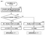
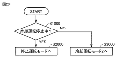
- FIG. 10 is a flow chart showing the contents of the operation mode control according to the first embodiment.
- the control device 30 switches the operation mode between the cooling operation mode and the stop operation mode by executing the processing based on this flowchart.
- the control device 30 first determines whether or not the cooling operation has stopped (step S1). When the operation of the low-concentration refrigerant circuit 300 is stopped due to a power failure or other circumstances, the control device 30 determines YES in step S1, and shifts to the stop operation mode (step S2). When the operation of the low-concentration refrigerant circuit 300 has not stopped, the control device 30 determines NO in step S1, and shifts to the cooling operation mode (step S3).
- the processing of the stop mode of operation is disclosed in FIG.
- the processing of the cooling mode of operation is disclosed in FIG.
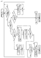
- FIG. 11 is a flow chart showing the contents of control in the stop operation mode.
- Control device 30 first determines whether P10 exceeds threshold value B (step S10).
- P10 indicates the pressure of the low-concentration refrigerant circuit 300 .
- Control device 30 specifies pressure P ⁇ b>10 based on the output value of pressure sensor 10 provided in low-concentration refrigerant circuit 300 .
- the control device 30 controls the pressure P10 of the low-concentration refrigerant circuit 300 within a certain range in the stop operation mode.
- a frame W10 in FIG. 11 shows the relationship between the pressure P10 and the threshold.
- the control device 30 controls the pressure so that it does not exceed the threshold value B.
- FIG. (1), (2), and (3) shown in frame W10 in FIG. 11 indicate the range of pressure P10 detected by pressure sensor 10. In FIG. Among (1) to (3), the reference range of pressure targeted by the control device 30 is (2).
- the threshold A is preferably 3.38 MPaG. It is assumed that the pressure of CO2 is 3.38 MPaG when the saturation temperature of CO2 is 0°C. Threshold B is preferably 3.67 MPaG. It is assumed that the pressure of CO2 is 3.67 MPaG when the saturation temperature of CO2 is 3°C.
- the threshold pressure range may be 3.38 MPaG to 4.15 MPaG. This corresponds to a saturation temperature of CO2 of 0°C to 7.7°C.
- the threshold A may be a value corresponding to the temperature when the saturation temperature of CO2 is less than 0.degree.
- step S10 When the control device 30 determines that P10 does not exceed the threshold B in step S10, the determination in step S10 is repeated until P10 exceeds the threshold B.
- the control device 30 determines in step S10 that the pressure P10 exceeds the threshold value B, the control device 30 operates the second high-order refrigerating cycle (step S11). Thereby, the second high-level refrigerant circuit 200 is activated.
- the second cascade condenser 204 cools the third refrigerant.
- Step S101 is a process for adjusting the rotational speed of the second fan 2021 of the second heat exchanger 202 and the opening degree of the second expansion valve 203, and is composed of steps S12 and S13.
- step S12 the control device 30 determines whether the current rotation speed of the second fan 2021 has reached the target condensation temperature (CT), and whether the current opening degree of the second expansion valve (LEV) 203 is It is determined whether the target degree of superheat (SH: superheat) has been achieved. When each target is achieved, the control device 30 proceeds to S14. If the respective targets are not achieved, the control device 30 resets the rotational speed of the second fan 2021 and the opening degree of the second expansion valve 203, and then proceeds to step S12 again.
- CT target condensation temperature
- SH target degree of superheat
- step S101 the control device 30 determines whether the pressure P10 satisfies "pressure P10 ⁇ threshold B" and "pressure P10>threshold A" (step S14). That is, the control device 30 determines whether or not the pressure P10 is within the range (2) shown in the frame W10.
- the control device 30 repeats the process of step S14.
- the control device 30 determines whether the pressure P10 satisfies "pressure P10 ⁇ threshold A". Here, it is determined whether or not the pressure P10 is within the range (1) shown in the frame W10.
- step S15 when the pressure P10 does not satisfy "pressure P10 ⁇ threshold A", the pressure P10 is within the range of (3) shown in the frame W10. Therefore, when the control device 30 determines NO in step S15, the frequency of the second compressor 201 (Comp 201) is increased by a constant value (step S16). After that, the control device 30 executes the same process as that of step S101 already described (step S17). After that, the control device 30 proceeds to the process of step S14.
- step S15 when the pressure P10 satisfies "pressure P10 ⁇ threshold A", the pressure P10 is within the range (1) shown in the frame W10. In this case, it can be determined that the pressure in the low-concentration refrigerant circuit 300 is sufficiently low. In other words, it can be determined that the cooling capacity of the high-order refrigeration cycle is too high. In this case, it is necessary to lower the frequency of the second compressor 201 . However, there is a possibility that the frequency of the second compressor 201 has already reached the lower limit frequency.
- control device 30 determines YES in step S15, it determines whether the frequency of the second compressor 201 (Comp 201) is the lower limit frequency and whether the outside air temperature is equal to or lower than the set temperature (step S20). Control device 30 identifies the outside air temperature based on the output value of temperature sensor 20 .
- step S20 When the control device 30 determines NO in step S20, the frequency of the second compressor 201 (Comp 201) is lowered by a certain value (step S18). After that, the control device 30 executes the same process as that of step S101 already described (step S19). After that, the control device 30 proceeds to the process of step S14.
- step S21 the control device 30 stops the second high-level refrigeration cycle (step S21). If the outside air temperature is equal to or less than the set temperature and the frequency of the second compressor 201 (Comp 201) is the lower limit frequency, it can be determined that there is no danger of the pressure of the low-level refrigerant circuit 300 suddenly rising. Therefore, the second high-level refrigeration cycle is stopped in step S21. After that, the processing of the stop operation mode is terminated.
- control device 30 controls first high-level refrigerant circuit 100 and second high-level refrigerant circuit 100 so that the pressure detected by pressure sensor 10 falls within the range of threshold A to threshold B in the stopped operation mode.
- the high-level refrigerant circuit 200 is controlled.
- the second high-order refrigeration cycle prevents the pressure of the low-order refrigerant circuit 300 from abnormally increasing.
- the first high-order refrigeration cycle may also be utilized in the stop operation mode. For example, in step S16 of FIG. 11, when the frequency of the second compressor 201 (Comp 201) has reached the upper limit frequency, it is conceivable to start the first high-order refrigeration cycle.
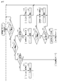
- FIG. 12 is a flow chart showing the contents of control in the cooling operation mode.
- the control device 30 first sets the target frequency of the third compressor 301 (Comp 301) from the outside air temperature and the evaporation temperature set in the indoor unit 2 (step S30).
- Control device 30 identifies the outside air temperature based on the output value of temperature sensor 20 .
- the control device 30 determines whether or not the frequency of the third compressor 301 (Comp 301) exceeds the threshold value X (step S31).
- the threshold X is a value for determining the required operability of the high-order refrigeration cycle.
- controller 30 determines that the frequency of third compressor 301 (Comp 301) exceeds threshold value X
- controller 30 operates the first and second high-order refrigeration cycles (step S32).
- the control device 30 determines that the frequency of the third compressor 301 (Comp 301) does not exceed the threshold value X, it operates the second high-order refrigerating cycle (step S34).
- control device 30 determines the timing of starting the first high-order refrigerant circuit 100 and the second high-order refrigerant circuit 200 based on the frequency set when starting the third compressor 301 (Comp 301). Control.
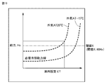
- FIG. 13 is a graph showing the relationship between the set value of the evaporation temperature inside the refrigerator and the cooling capacity.
- the threshold value X will be described with reference to FIG. 13 .
- the horizontal axis indicates the condensation temperature (ET: Evaporation Temperature) set in the indoor unit 2 arranged in the refrigerator.
- the vertical axis indicates the compressor frequency (Hz) corresponding to the cooling capacity.
- the required cooling capacity changes depending on the outside air temperature AT (Outside Air Temperature).
- FIG. 13 shows an example in which the outside air temperature is 20.degree. C. and -15.degree.
- the threshold X is set to 60 Hz based on this graph. However, this value is only an example.
- step S32 When the first and second high-order refrigerating cycles are operated in step S32, the control device 30 performs the same process as in step S101 already described in the first and second high-order refrigerating cycles (step S33).
- the control device 30 executes the high capacity operation mode.
- the processing of the high capacity mode of operation is disclosed in FIG.
- step S34 When the second high-level refrigerating cycle is operated in step S34, the control device 30 performs the same processing as in step S101 already described in the second high-level refrigerating cycle (step S35). Thereby, in the second high-voltage refrigerant circuit 200, the rotational speed of the second fan 2021 of the second heat exchanger 202 and the opening degree of the second expansion valve 203 are adjusted as necessary. After step S35, the control device 30 executes the low capacity operation mode. The processing of the low capacity mode of operation is disclosed in FIG.
- FIG. 14 is a flow chart showing the contents of control in the high capacity operation mode.
- the control device 30 first determines whether or not the pressure P10 satisfies "P10 ⁇ threshold B" and "P10 ⁇ threshold A" (step S40). As already explained using FIG. 11 , P10 indicates the pressure of the low-concentration refrigerant circuit 300 .
- Control device 30 specifies pressure P ⁇ b>10 based on the output value of pressure sensor 10 provided in low-concentration refrigerant circuit 300 . The relationship between pressure P10 and threshold A and threshold B is shown in frame W10 in FIG.
- control device 30 determines whether the pressure P10 satisfies "P10 ⁇ threshold A" (step S41).
- step S41 when the pressure P10 satisfies "P10 ⁇ threshold A", the pressure P10 is within the range (1) indicated by the frame W10 in FIG. At this time, the pressure P10 is a value lower than the lower threshold A. In this case, it can be determined that the pressure in the low-concentration refrigerant circuit 300 is sufficiently low. In other words, it can be determined that the cooling capacity of the high-order refrigeration cycle is too high. In this case, it is necessary to lower the frequency of the compressor on the high-order refrigerating cycle side. However, there is a possibility that both the frequencies of the first compressor 101 and the second compressor 201 on the high-order refrigerating cycle side have already reached the lower limit frequency.
- control device 30 determines YES in step S41, it determines whether or not the frequencies of the first compressor 101 (Comp 101) and the second compressor 201 (Comp 201) both reach the lower limit frequency (step S43).
- control device 30 When determining NO in step S43, the control device 30 reduces the frequency of the compressor of the high-level refrigeration cycle (step S52). In step S52, control device 30 preferentially lowers the frequency of first compressor 101 (Comp101) out of first compressor 101 (Comp101) and second compressor 201 (Comp201).
- step S53 if the frequency of the first compressor 101 (Comp 101) has reached the lower limit and the frequency of the second compressor 201 (Comp 201) has not reached the lower After lowering the frequency of the compressor 201 (Comp 201) by a constant value, the process proceeds to step S53.
- step S53 the control device 30 executes the same process as in step S101 already described in the first and second high-level refrigeration cycles.
- control device 30 returns the process to step S40.
- step S43 the frequencies of both the first compressor 101 (Comp101) and the second compressor 201 (Comp201) may eventually reach the lower limit.
- the controller 30 determines YES in step S43. At this time, the cooling capacity of the high-order refrigeration cycle when both the first and second high-order refrigeration cycles are activated reaches the lower limit.
- step S43 the control device 30 stops the first high-level refrigeration cycle (step S54), and then switches the operation mode from the high-capacity operation mode to the low-capacity operation mode.
- step S41 when the pressure P10 does not satisfy "P10 ⁇ threshold A", the pressure P10 is within the range (3) indicated by the frame W10 in FIG. At this time, the pressure P10 has a value exceeding the upper limit threshold B.
- step S41 determines in step S41 that the pressure P10 does not satisfy "P10 ⁇ threshold A"
- the frequencies of the first compressor 101 (Comp101) and the second compressor 201 (Comp201) are both upper limit values. is reached (step S42).
- control device 30 When determining NO in step S42, the control device 30 increases the frequency of the compressor of the high-level refrigeration cycle (step S44). In step S44, control device 30 preferentially increases the frequency of second compressor 201 (Comp 201) out of first compressor 101 (Comp 101) and second compressor 201 (Comp 201).
- step S45 when the frequency of the second compressor 201 (Comp 201) has not reached the upper limit, the frequency of the second compressor 201 (Comp 201) is increased by a certain value, and then the process proceeds to the next step S45. At this time, the frequency of the first compressor 101 (Comp101) is not increased.
- step S42 when the frequency of the second compressor 201 (Comp 201) has reached the upper limit and the frequency of the first compressor 101 (Comp 101) has not reached the upper limit, in step S44, the control device 30 controls the first After increasing the frequency of the compressor 101 (Comp 101) by a constant value, the process proceeds to step S45.
- step S45 the control device 30 executes the same process as in step S101 already described in the first and second high-level refrigerating cycles.
- control device 30 returns the process to step S40.
- step S44 the frequencies of both the first compressor 101 (Comp101) and the second compressor 201 (Comp201) may eventually reach the upper limits.
- the control device 30 determines YES in step S42. At this time, the cooling capacity of the high-level refrigeration cycle has reached its upper limit.
- control device 30 If it is determined YES in step S42, the control device 30 notifies the user of the lack of ability (step S46).
- the control device 30 displays, for example, a message indicating insufficient capacity on a remote controller for operating the indoor unit 2 .
- step S46 the control device 30 lowers the frequency of the third compressor 301 (Comp 301) constituting the low-concentration refrigerant circuit 300 by a certain value (step S47).
- Control device 30 performs the same processing as step S101 already described for each refrigerating cycle (step S48). After that, the control device 30 determines whether or not the pressure P10 satisfies "P10 ⁇ threshold B" (step S49).
- step S49 if the pressure P10 does not satisfy "P10 ⁇ threshold B", the control device 30 returns the process to step S46.
- step S49 when pressure P10 satisfies "P10 ⁇ threshold B", control device 30 determines whether or not a user's operation to stop the low-order refrigeration cycle has been detected (step S50). Control device 30 continues the processing of step S50 until the user's operation for stopping the low-order refrigeration cycle is detected. A user's operation is input to the control device 30 from, for example, a remote controller corresponding to the indoor unit 2 . Note that, when the control device 30 determines NO in step S50, the control device 30 may return the processing to step S46 and notify the user of the lack of ability again.
- control device 30 When the control device 30 detects the user's operation in step S50, it stops the low-level refrigerating cycle and the first high-level refrigerating cycle (step S51). Next, the control device 30 switches the operation mode to the stop operation mode. By switching the operation mode to the stop operation mode, the pressure of the low-concentration refrigerant circuit 300 is prevented from increasing abnormally.
- control device 30 controls first high-level refrigerant circuit 100 and second high-level refrigerant circuit 100 so that the pressure detected by pressure sensor 10 falls within the range of threshold A to threshold B in the high-capacity operation mode. It controls the two-level refrigerant circuit 200 .
- FIG. 15 is a flowchart showing the details of control in the low capacity operation mode.
- the control device 30 first determines whether or not the pressure P10 satisfies "P10 ⁇ threshold B" and "P10 ⁇ threshold A" (step S70). As already explained using FIG. 11 , P10 indicates the pressure of the low-concentration refrigerant circuit 300 .
- Control device 30 specifies pressure P ⁇ b>10 based on the output value of pressure sensor 10 provided in low-concentration refrigerant circuit 300 . The relationship between pressure P10 and threshold A and threshold B is shown in frame W10 in FIG.
- control device 30 determines whether the pressure P10 satisfies "P10 ⁇ threshold A" (step S71).
- step S71 when the pressure P10 satisfies "P10 ⁇ threshold A", the pressure P10 is within the range (1) indicated by the frame W10 in FIG. At this time, the pressure P10 is a value lower than the lower threshold A. In this case, it can be determined that the pressure in the low-concentration refrigerant circuit 300 is sufficiently low. In other words, it can be determined that the cooling capacity of the high-order refrigeration cycle is too high. In this case, it is necessary to lower the frequency of the second compressor 201 activated on the high-order refrigerating cycle side. However, there is a possibility that the frequency of the second compressor 201 has already reached the lower limit frequency.
- control device 30 determines YES in step S71, it determines whether or not the frequency of the second compressor 201 (Comp 201) has reached the lower limit frequency (step S73).
- control device 30 When determining NO in step S73, the control device 30 reduces the frequency of the second compressor 201 (Comp 201) by a constant value (step S76). After that, in step S77, control device 30 performs the same process as in step S101 already described in the second high-order refrigeration cycle. After step S77, control device 30 returns the process to step S70.
- step S76 the frequency of the second compressor 201 (Comp 201) may eventually reach the lower limit.
- the control device 30 determines YES in step S73. At this time, the cooling capacity of the second high-order refrigeration cycle has reached its lower limit.
- control device 30 When determining YES in step S73, the control device 30 increases the target degree of superheat (SH) by adjusting the degree of opening of the third expansion valve 303 that constitutes the low-concentration refrigerant circuit 300 (step S78). After that, in step S79, control device 30 performs the same process as in step S101 already described in the low-order refrigeration cycle. Specifically, control device 30 adjusts the rotation speed of third fan 3021 of third heat exchanger 302 .
- SH target degree of superheat
- step S79 the control device 30 determines whether or not the pressure P10 satisfies "P10 ⁇ threshold B" and "P10 ⁇ threshold A” (step S80). If the pressure P10 does not satisfy "P10 ⁇ threshold B" and "P10 ⁇ threshold A”, the control device 30 again adjusts the target degree of superheat (SH) of the third expansion valve 303 (step S81). Thereafter, control device 30 executes the same process as step S79 (step S82), and returns the process to step S70.
- SH target degree of superheat
- step S83 the control device 30 determines whether or not the user's stop operation has been detected.
- the user for example, operates the remote controller to stop the low-level refrigeration cycle.
- step S83 the control device 30 returns the process to step S70.
- step S84 control device 30 stops the low-order refrigeration cycle (step S84). After that, the control device 30 switches the operation mode to the stop operation mode.
- step S71 if the pressure P10 does not satisfy "P10 ⁇ threshold A", the pressure P10 is within the range (3) indicated by the frame W10 in FIG. At this time, the pressure P10 has a value exceeding the upper limit threshold B.
- step S71 determines whether the frequency of the second compressor 201 (Comp 201) has reached the upper limit (step S72).
- step S72 the control device 30 increases the frequency of the second compressor 201 (Comp 201) by a constant value (step S74). After that, the control device 30 executes the same process as the already described step S101 in the second high-level refrigerating cycle (step S75). After step S75, control device 30 returns the process to step S70.
- step S74 the frequency of the second compressor 201 (Comp 201) may eventually reach the upper limit.
- the controller 30 determines YES in step S72 and switches the operation mode to the high capacity operation mode. By switching the operation mode to the high-capacity operation mode, the second high-level refrigerating cycle is activated and the refrigerating capacity of the high-level refrigerating cycle increases.
- control device 30 controls first high-level refrigerant circuit 100 and second high-level refrigerant circuit 100 so that the pressure detected by pressure sensor 10 falls within the range of threshold A to threshold B in the low capacity operation mode. It controls the two-level refrigerant circuit 200 .
- the control device 30 switches the operation mode between the stop operation mode and the cooling operation mode depending on the situation. More specifically, in both the stop operation mode and the cooling operation mode, the control device 30 controls the pressure detected by the pressure sensor 10 to fall within the range of the threshold A to the threshold B.
- the high-order refrigerant circuit 100 and the second high-order refrigerant circuit 200 are controlled. Note that the threshold may be varied according to each mode.
- the control device 30 operates in the low capacity operation mode or in the high capacity operation mode based on the frequency set when starting the third compressor 301 (Comp 301). decide whether to In particular, in the high-capacity operation mode, both the first and second high-order refrigeration cycles are activated on the high-order side. On the other hand, in the low capacity operation mode, only the second high-order refrigeration cycle is started on the high-order side. Therefore, the control device 30 controls the timing of starting the first high-order refrigerant circuit 100 and the second high-order refrigerant circuit 200 based on the frequency set when starting the third compressor 301 .
- control device 30 switches the cooling operation mode between the low-capacity operation mode and the high-capacity operation mode according to the degree of required cooling capacity. switch.
- control device 30 changes the cooling capacity of the high-level refrigeration cycle provided by the first high-level refrigerant circuit 100 and the second high-level refrigerant circuit 200 based on the state of the refrigeration cycle of the low-level refrigerant circuit 300.
- the high-level refrigeration cycle is designed so that the cooling capacity of the first high-level refrigeration cycle and the cooling capacity of the second high-level refrigeration cycle overlap. is effective when the starting high-side refrigeration cycle changes in this way.
- the cooling capacity that can be output at the upper limit frequency of the second higher refrigeration cycle is set to be greater than the cooling capacity that can be output at the lower limit frequency of the first higher refrigeration cycle.
- the operation can be switched smoothly from the second high-order refrigeration cycle to the first high-order refrigeration cycle. Therefore, the required cooling capacity can be obtained without excessively lowering the frequency of the second compressor 201 .
- the compressor motor may burn out.
- it is not necessary to excessively lower the frequency of the second compressor 201 it is possible to prevent the motor of the second compressor 201 from burning out due to lack of refrigerating machine oil. reliability can be improved.
- FIG. 16 is a diagram showing the configuration of a dual refrigeration cycle device 52 according to the second embodiment.
- the binary refrigerating cycle device 52 according to the second embodiment has a fourth heat exchanger 402 added to the configuration of the binary refrigerating cycle device 51 according to the first embodiment.
- the fourth heat exchanger 402 is provided with a fourth fan 4021 that facilitates heat exchange between the outside air and the third refrigerant.
- a fourth heat exchanger 402 is provided in the low-concentration refrigerant circuit 300 .
- a fourth heat exchanger 402 is connected between the first cascade condenser 104 and the first compressor 101 .
- the high-temperature and high-pressure gaseous third refrigerant discharged from the first compressor 101 is input to the fourth heat exchanger 402 .
- the fourth heat exchanger 402 radiates the heat of the third refrigerant discharged from the first compressor 101 to the air. Therefore, the fourth heat exchanger 402 functions as a condenser.
- the binary refrigerating cycle device 51 related to Embodiment 1 already described has two cooling operation modes, a low-capacity operation mode and a high-capacity operation mode. In these two modes, the high order refrigeration cycle is activated and the third refrigerant of the low order refrigeration cycle is cooled.
- the binary refrigeration cycle device 52 according to Embodiment 2 cools the third refrigerant by the fourth heat exchanger 402 without starting the high-capacity refrigeration cycle in addition to the low-capacity operation mode and the high-capacity operation mode. have a mode.
- this mode will be referred to as a "low cooling mode”.
- the cooling operation mode of the second embodiment has a larger number of switchable modes than the cooling operation mode of the first embodiment.
- the latter cooling operation mode may be particularly referred to as "cooling operation mode 2".
- rotation of the fourth fan 4021 corresponding to the fourth heat exchanger 402 cools the third refrigerant flowing through the low temperature refrigerant circuit 300 .
- the binary refrigerating cycle device 52 may control the rotation speed of the fourth fan 4021 based on the output value of the pressure sensor 10 in order to keep the pressure of the third refrigerant proper.
- the binary refrigeration cycle device 52 switches the operation mode from the low-primary cooling mode to the low-capacity operation mode.
- the content of the low capacity operation mode is the same as that of the first embodiment.
- the fourth heat exchanger 402 also continues to function as a condenser. Therefore, in the low capacity operation mode related to Embodiment 2, the fourth fan 4021 corresponding to the fourth heat exchanger 402 is rotating. Therefore, the low capacity operation mode according to the second embodiment has a higher maximum cooling capacity than the low capacity operation mode according to the first embodiment.
- control device 30 controls the rotation speed of fourth fan 4021 based on the output value of pressure sensor 10 in order to keep the pressure of the third refrigerant appropriate. good too.
- the binary refrigeration cycle device 52 switches the operation mode from the low-capacity operation mode to the high-capacity operation mode.
- the content of the high capacity operation mode is the same as that of the first embodiment.
- the fourth heat exchanger 402 also continues to function as a condenser. Therefore, in the low capacity operation mode related to Embodiment 2, the fourth fan 4021 corresponding to the fourth heat exchanger 402 is rotating. Therefore, the high capacity operation mode according to the second embodiment has a higher maximum cooling capacity than the low capacity operation mode according to the first embodiment.
- control device 30 controls the rotation speed of fourth fan 4021 based on the output value of pressure sensor 10 in order to keep the pressure of the third refrigerant appropriate. good too.
- FIG. 17 is a diagram showing the ratio of the heat transfer area of the first heat exchanger 102 and the second heat exchanger 202 to the heat transfer area of the fourth heat exchanger 402.
- the first heat exchanger 102 and the second heat exchanger 202 form a condenser of the high-level refrigeration cycle
- the fourth heat exchanger 402 forms a condenser of the low-level refrigeration cycle. Therefore, FIG. 17 corresponds to a diagram comparing the heat transfer areas of the condenser of the high-order refrigeration cycle and the condenser of the low-order refrigeration cycle.
- pattern 1 and pattern 2 are shown in FIG. 17.
- pattern 1 the ratio of the heat transfer area of the fourth heat exchanger 402 to the total heat transfer area of the first heat exchanger 102, the second heat exchanger 202, and the fourth heat exchanger 402 is 3% to 50%. is considered to be in the range of That is, pattern 1 is an example in which the ratio of the heat transfer area of the low-order refrigeration cycle to the total heat transfer area of the condensers of the low-order refrigeration cycle and the high-order refrigeration cycle is in the range of 3% to 50%.
- pattern 2 the ratio of the heat transfer area of the fourth heat exchanger 402 to the total heat transfer area of the first heat exchanger 102, the second heat exchanger 202, and the fourth heat exchanger 402 is 8% to 30%. is considered to be in the range of That is, pattern 2 is an example in which the ratio of the heat transfer area of the low-order refrigeration cycle to the total heat transfer area of the condensers of the low-order refrigeration cycle and the high-order refrigeration cycle is in the range of 8% to 30%.
- pattern 2 is more desirable to adopt pattern 2 than pattern 1 as the heat transfer area ratio.
- pattern 2 since pattern 2 has a higher heat transfer area ratio of the condenser of the low-order refrigeration cycle than pattern 1, pattern 2 is higher than pattern 1 in the low-order cooling mode using the fourth heat exchanger 402. It can be expected that the cooling function of
- any of the heat transfer ratio of the fourth heat exchanger 402 within the range of 3 to 50% may be adopted.
- any heat transfer ratio within the range of 8 to 30% of the fourth heat exchanger 402 may be adopted.
- FIG. 18 shows a sixth heat exchanger 602 in which the first heat exchanger 102, the second heat exchanger 202 and the fourth heat exchanger 402 are integrated.
- the sixth heat exchanger 602 corresponds to the integrated components indicated by symbols B, C, and D in FIG. 16 .
- the sixth heat exchanger 602 is divided into a first high-level refrigerant circuit 100 in which the first refrigerant flows, a second high-level refrigerant circuit 200 in which the second refrigerant flows, and a low-level refrigerant circuit 300 in which the third refrigerant flows.
- the first heat exchanger 102, the second heat exchanger 202, and the fourth heat exchanger 402 are integrated.
- a sixth fan 6021 is provided in the sixth heat exchanger 602 . However, a plurality of fans may be provided for sixth heat exchanger 602 .
- the space for arranging the equipment can be effectively utilized. Also, by integrating the first heat exchanger 102, the second heat exchanger 202, and the fourth heat exchanger 402, the cost can be reduced.
- FIG. 19 shows a seventh heat exchanger 702 that integrates the second heat exchanger 202 and the fourth heat exchanger 402, and the first heat exchanger 102 used in combination with the seventh heat exchanger 702. It is a diagram.
- a seventh heat exchanger 702 is obtained by integrating the constituent parts indicated by symbols B and C in FIG.
- the seventh heat exchanger 702 is divided into the second high-level refrigerant circuit 200 in which the second refrigerant flows and the low-level refrigerant circuit 300 in which the third refrigerant flows, and the second heat exchanger 202 and the fourth heat exchanger are divided. 402 are integrated.
- a seventh fan 7021 is provided in the seventh heat exchanger 702 . However, a plurality of fans may be provided for the seventh heat exchanger 702 .
- the space for arranging equipment can be effectively utilized. Also, by integrating the second heat exchanger 202 and the fourth heat exchanger 402, the cost can be reduced. Note that the first heat exchanger 102 and the fourth heat exchanger 402 may be integrated.
- FIG. 20 is a flow chart showing the contents of the operation mode control according to the second embodiment.
- the control device 30 switches the operation mode between the cooling operation mode 2 and the stop operation mode by executing the processing based on this flowchart.
- the control device 30 first determines whether the cooling operation has stopped (step S1000). When the operation of the low-concentration refrigerant circuit 300 is stopped due to a power failure or other circumstances, the control device 30 determines YES in step S1000, and shifts to the stop operation mode (step S2000).
- control device 30 determines NO in step S1000, and shifts to cooling operation mode 2 (step S3000).
- FIG. 21 is a flowchart showing the contents of control in cooling operation mode 2.
- the control device 30 first sets the target frequency of the third compressor 301 (Comp 301) from the outside air temperature and the evaporation temperature set in the indoor unit 2 (step S90).
- Control device 30 identifies the outside air temperature based on the output value of temperature sensor 20 .
- the control device 30 determines whether the frequency of the third compressor 301 (Comp 301) is equal to or lower than the threshold value Y, and whether the outside air (outside air temperature) is equal to or lower than the set value (step S91).
- the set value of the outside air temperature is a preset value. The set value of the outside air temperature will be described later with reference to FIG. 22 .
- the controller 30 stores set values.
- the control device 30 stores a threshold X and a threshold Y as thresholds for determining whether to switch the operation of the refrigeration cycle.
- a frame W20 in FIG. 21 shows the relationship between the frequency of the third compressor 301 (Comp 301) and the threshold values X and Y. As shown in FIG. First, the relationship between the frequency of the third compressor 301 (Comp 301) and the thresholds X and Y will be described with reference to the frame W20.
- (1) to (3) in the frame W20 indicate the range of frequency values of the third compressor 301 (Comp 301).
- (1) indicates a range in which the frequency of the third compressor 301 (Comp 301) is equal to or lower than the threshold value Y;
- (2) indicates a range in which the frequency of the third compressor 301 (Comp 301) exceeds the threshold value Y and is less than the threshold value X;
- (3) indicates a range in which the frequency of the third compressor 301 (Comp 301) is equal to or higher than the threshold value X;
- Frequency range (2) indicates the appropriate range.
- Frequency range (1) indicates a range lower than the proper range.
- Frequency range (3) indicates a range that is higher than the proper range.
- FIG. 22 is a graph showing the relationship between the set value of the evaporating temperature inside the refrigerator and the cooling capacity (Embodiment 2).
- FIG. 23 is a graph showing the relationship between the frequency of the third compressor (Comp301) and the set value of the evaporating temperature inside the refrigerator (Embodiment 2).
- the threshold value X and the set value of the outside air temperature will be described with reference to FIG. 22, and the threshold value Y will be described with reference to FIG.
- the horizontal axis indicates the condensation temperature (ET: Evaporation Temperature) set in the indoor unit 2 placed inside the refrigerator.
- the vertical axis indicates the compressor frequency (Hz) corresponding to the cooling capacity.
- the required cooling capacity changes depending on the outside air temperature AT (Outside Air Temperature).
- FIG. 22 shows an example in which the outside air temperature is 20.degree. C. and -15.degree.
- the threshold value X is set to 60 Hz based on this graph. However, this value is only an example.
- FIG. 22 further shows a region R10 where high-level operation is unnecessary.
- region R10 it is not necessary to operate either the first or second high-order refrigeration cycle while the low-order refrigeration cycle is in operation.
- control device 30 selects the low-level cooling mode as the operation mode.
- the fourth heat exchanger 402 provided in the low temperature refrigerant circuit 300 functions as a condenser to cool the third refrigerant.
- the high temperature refrigeration cycle does not start.
- the region R10 is set with the outside air temperature AT10 as the boundary. That is, the control device 30 selects the low-level cooling mode on the condition that the outside air temperature is AT10 or less.
- the outside air temperature AT10 is set to any value within the range of -15°C to 20°C.
- the horizontal axis indicates the frequency of the third compressor 301 (Comp 301).
- the vertical axis indicates the condensing temperature (ET) set in the indoor unit 2 placed inside the refrigerator.
- a region R10 where high-level operation is unnecessary and a region R20 where high-level operation is required is shown.
- Region R20 is bounded by capacity equivalence lines. The higher the frequency and condensing temperature (ET) of the third compressor 301 (Comp 301), the higher the required cooling capacity.
- FIG. 23 shows Y1 and Y2 as examples of values that can be used as the threshold Y.
- the threshold value Y1 is the maximum frequency of the third compressor 301 (Comp 301) in the region R10 where high-level operation is not required. Y1 is therefore a fixed value.
- the threshold Y2 is the frequency of the third compressor 301 (Comp 301) along the capacity equivalence line. Therefore, Y2 is a value that varies according to the condensation temperature (ET) set in the indoor unit 2.
- either Y1 or Y2 may be used as the threshold value Y.
- two thresholds Y1 and Y2 may be stored in the memory 32 of the control device 30 in advance.
- the control device 30 may be configured to be able to select which of Y1 and Y2 thresholds to use.
- step S91 the control device 30 performs an operation to rotate the fourth fan 4021 of the fourth heat exchanger 402 (step S95). That is, the control device 30 starts operation in the low-level cooling mode. Thereby, the fourth heat exchanger 402 functions as a condenser. As a result, the third refrigerant in the low-concentration refrigerant circuit 300 is cooled by the fourth heat exchanger 402 .
- control device 30 determines whether the frequency of the third compressor 301 (Comp 301) exceeds the threshold Y and the frequency of the third compressor 301 (Comp 301) is less than the threshold X (step S96). That is, control device 30 determines whether or not the frequency of third compressor 301 is within proper range (2) shown in frame W20.
- step S99 When determining YES in step S96, the control device 30 operates the second high-level refrigeration cycle (step S99). When the second high-order refrigeration cycle is to be operated, the control device 30 performs the same process as in step S101 already described in the second high-order refrigeration cycle (step S100). Thereby, in the second high-voltage refrigerant circuit 200, the rotational speed of the second fan 2021 of the second heat exchanger 202 and the opening degree of the second expansion valve 203 are adjusted as necessary.
- the control device 30 executes the low capacity operation mode after step S100.
- the processing of the low capacity mode of operation is disclosed in FIG.
- the processing of the low-capacity operation in the second embodiment is the same as the content of the control in the low-capacity operation mode of the first embodiment shown in FIG. 15, so description thereof will not be repeated here.
- the operation of the fourth fan 4021 of the fourth heat exchanger 402 shown in step S95 is continued.
- control device 30 When determining NO in step S96, the control device 30 operates the first and second high-level refrigeration cycles (step S97).
- step S97 When the first and second high-order refrigeration cycles are operated in step S97, the control device 30 performs the same processing as in step S101 already described in the first and second high-order refrigeration cycles (step S98).
- the rotational speed of the first fan 1021 of the first heat exchanger 102 and the opening degree of the first expansion valve 103 are adjusted as necessary.
- the rotational speed of the second fan 2021 of the second heat exchanger 202 and the opening degree of the second expansion valve 203 are adjusted as necessary.
- the control device 30 executes the high capacity operation mode after step S98.
- the processing of the high capacity mode of operation is disclosed in FIG.
- the high-capacity operation processing of the second embodiment is the same as the control contents of the high-capacity operation mode of the first embodiment shown in FIG. 14, and thus description thereof will not be repeated here.
- the operation of the fourth fan 4021 of the fourth heat exchanger 402 shown in step S95 is continued.
- step S91 When determining YES in step S91, the control device 30 performs an operation to rotate the fourth fan 4021 of the fourth heat exchanger 402 (step S92). This process is similar to step S95 already described.
- control device 30 determines whether or not the pressure P10 of the low-concentration refrigerant circuit 300 exceeds the threshold value B (step S93).
- P10 indicates the pressure of the low-concentration refrigerant circuit 300.
- Control device 30 specifies pressure P ⁇ b>10 based on the output value of pressure sensor 10 provided in low-concentration refrigerant circuit 300 .
- the relationship between pressure P10 and threshold A and threshold B is shown in frame W10 in FIG.
- step S93 When the pressure P10 does not exceed the threshold value B in step S93, the pressure P10 does not exceed the upper limit of the set pressure range. Therefore, if the control device 30 determines NO in step S93, the determination in step S93 is repeated until the pressure P10 exceeds the threshold value B.
- step S93 When the pressure P10 exceeds the threshold value B in step S93, it can be determined that heat radiation is insufficient with the fourth heat exchanger 402 alone. Therefore, when the determination in step S93 is YES, the control device 30 operates the second high-order refrigeration cycle in order to reduce the pressure P10 to the range of (2) in the frame W10 of FIG. 11 (step S94). Thereby, the second high-level refrigerant circuit 200 is activated. When the second high-order refrigerant circuit 200 is activated, the second cascade condenser 204 cools the third refrigerant.
- the control device 30 activates the second high-level refrigerant circuit 200 when the pressure P10 becomes higher than the range from the threshold value A to the threshold value B even if the fourth heat exchanger 402 is activated.
- the low capacity operation mode is executed.
- the details of the control in the low capacity operation mode are disclosed in FIG.
- the processing of the low-capacity operation in the second embodiment is the same as the content of the control in the low-capacity operation mode of the first embodiment shown in FIG. 15, so description thereof will not be repeated here.
- the operation of the fourth fan 4021 of the fourth heat exchanger 402 shown in step S92 is continued.
- the pressure of the third refrigerant is abnormally increased by using the heat radiation function of the fourth heat exchanger 402 provided in the low-concentration refrigerant circuit 300. prevent it from rising. At this time, there is no need to operate the high-level refrigeration cycle. Therefore, it is possible to operate the refrigeration cycle with high efficiency.
- the control device 30 controls the timing of starting the first high-order refrigerant circuit 100 and the second high-order refrigerant circuit 200 based on the frequency set when starting the third compressor 301. do. Also in Embodiment 2, the low-capacity operation mode and the high-capacity operation mode are executed. The contents of the low-capacity operation mode and the high-capacity operation mode are as described in the first embodiment. However, in Embodiment 2, the fourth heat exchanger 402 is also activated. Therefore, the control device 30 according to the second embodiment controls the first high-order refrigerant circuit 100, the second high-order refrigerant circuit 200, and the 4 Control the heat exchanger 402 .
- the control device 30 controls the rotation speed of the fourth fan 4021 without activating the high temperature refrigeration cycle so that the pressure in the low temperature refrigerant circuit 300 becomes abnormal. prevent it from rising.
- the refrigeration cycle can be operated without activating the high-level refrigeration cycle, so the energy saving performance of the binary refrigeration cycle device 52 can be enhanced. Also, the service life of the high-order refrigeration cycle can be increased. As a result, the performance of the binary refrigeration cycle device 52 can be improved.
- the third refrigerant flowing from the third compressor 301 to the fourth heat exchanger 402 is superheated steam.
- the fourth heat exchanger 402 By activating the fourth heat exchanger 402 when the high-order refrigerating cycle is operated, part of the heat of the third refrigerant before flowing into the first cascade condenser 104 can be radiated by the fourth heat exchanger 402 . Therefore, in the first cascade condenser 104, heat can be exchanged between the third refrigerant and the first refrigerant in the two-phase region having a high heat transfer coefficient. The same applies to the second cascade capacitor 204 as well.
- the fourth fan 4021 of the fourth heat exchanger 402 is rotated without activating the high-level refrigeration cycle.
- the performance of the binary refrigerating cycle device 52 can be improved while suppressing an abnormal increase in the pressure of the low-concentration refrigerant circuit 300 when starting up the refrigerating cycle. For example, when the frequency of the third compressor 301 is lower than the threshold and the outside air temperature is lower than the set value, the dual refrigeration cycle device 52 is in a low load state.
- the fourth fan 4021 is rotated and the second high-order refrigeration cycle is started. Accordingly, in a situation where heat treatment cannot be performed only by the fourth heat exchanger 402, it is possible to reliably suppress an abnormal increase in the pressure of the low-concentration refrigerant circuit 300 from the start of the refrigeration cycle.
- the energy saving performance of the binary refrigerating cycle device 52 can be enhanced. Also, the service life of the high-order refrigeration cycle can be increased. As a result, the performance of the binary refrigeration cycle device 52 can be improved.
- the fourth fan 4021 may be rotated and the first and second high-order refrigerating cycles may be activated. Accordingly, in a situation where heat treatment cannot be performed only by the fourth heat exchanger 402 and the second high-order refrigeration cycle, it is possible to reliably suppress an abnormal increase in the pressure of the low-order refrigerant circuit 300 from the start of the refrigeration cycle.
- FIG. 24 is a flow chart showing a modification of cooling operation mode 2 according to the second embodiment. A modification of cooling operation mode 2 according to the second embodiment will be described with reference to FIG. 24 .
- the control device 30 first sets the target frequency of the third compressor 301 (Comp 301) from the outside air temperature and the evaporation temperature set in the indoor unit 2 (step S120).
- the processing of step S120 is the same as the processing of step S90 in FIG.
- the control device 30 determines whether or not the frequency of the third compressor 301 (Comp 301) is equal to or less than the threshold value Y (step S121). If the control device 30 determines that the frequency of the third compressor 301 set in step S120 is equal to or less than the threshold value Y, it determines whether the outside air temperature is equal to or less than the set value (step S122).
- the outside air temperature is the temperature detected by the temperature sensor 20 .
- the controller 30 When the controller 30 determines that the outside air temperature is equal to or lower than the set value, it performs an operation to rotate the fourth fan 4021 of the fourth heat exchanger 402 (step S123). This activates the fourth heat exchanger 402 . This process is the same as step S92 in FIG. After that, the control device 30 performs the processing of steps S124 to S125. This process is the same as the process of steps S93-S94 in FIG.
- step S122 When the controller 30 determines in step S122 that the outside air temperature is not equal to or lower than the set value, the controller 30 rotates the fourth fan 4021 of the fourth heat exchanger 402 and activates the second high-level refrigerant circuit 200 (step S126). ). Next, control device 30 executes the same process as already described in step S101 in the second high-level refrigerating cycle (step S127), and shifts to the low capacity operation mode.
- control device 30 determines in step S121 that the frequency of the third compressor 301 is not equal to or lower than the threshold value Y, it determines whether the outside air temperature is equal to or lower than the set value (step S128). When the control device 30 determines that the outside air temperature is equal to or lower than the set value, the control device 30 executes the process of step S126 already described.
- step S128 When the controller 30 determines in step S128 that the outside air temperature is not equal to or lower than the set value, the controller 30 rotates the fourth fan 4021 of the fourth heat exchanger 402 and rotates the first high-level refrigerant circuit 100 and the second high-level refrigerant circuit.
- the circuit 200 is activated (step S129).
- control device 30 executes the same process as already described in step S101 in the second high-level refrigeration cycle (step S130), and shifts to the high capacity operation mode.
- control device 30 controls the first high-order refrigerant circuit 100, the It controls the timing of starting the secondary refrigerant circuit 200 and the fourth heat exchanger 402 .
- any of the modifications of the first embodiment shown in FIGS. 4 to 7 may be applied to the second embodiment. Also, all of these modifications may be applied, or one or more of those modifications may be applied.
- the binary refrigerating cycle device 51 and the binary refrigerating cycle device 52 have a configuration in which one low-order refrigerating cycle is divided into two high-order refrigerating cycles.
- the binary refrigerating cycle device 51 and the binary refrigerating cycle device 52 may have a configuration in which one low-order refrigerating cycle is divided into three high-order refrigerating cycles.
- the binary refrigerating cycle device 51 and the binary refrigerating cycle device 52 may further include a third higher refrigerating cycle.
- the third high-order refrigeration cycle may have a higher cooling capacity than the first high-order refrigeration cycle.
- the third higher order refrigeration cycle may have a lower cooling capacity than the second higher order refrigeration cycle.
- a refrigerant different from the first to third refrigerants may be used in the third high-order refrigeration cycle. Any one of the first to third refrigerants may be used in the third high-order refrigeration cycle.
- a common type of refrigerant may be used in the first to third high-order refrigeration cycles.
- a discharge temperature sensor that detects the temperature of the high-temperature refrigerant discharged from the third compressor 301 may be provided on the discharge side of the third compressor 301 .
- a low pressure sensor may be provided on the suction side of the third compressor 301 to calculate the low pressure saturation temperature ET.
- controller 30 rotates fourth fan 4021 of fourth heat exchanger 402 both when YES and NO are determined in step S91. drive to let Alternatively, when determining NO in step S91, the control device 30 may proceed to the process of step S96 without rotating the fourth fan 4021 of the fourth heat exchanger 402.
- control device 30 may control the rotation speed of fourth fan 4021 based on the output value of pressure sensor 10 in order to keep the pressure of the third refrigerant appropriate. .
- the control device 30 determines NO in step S42 of the flowchart shown in FIG. 14, the rotation speed of the fourth fan 4021 of the fourth heat exchanger 402 may be increased to the maximum speed.
- the control device 30 may make the same determination as in step S41 before executing the process of step S44.
- the control device 30 may execute the process of step S44 when the pressure rise cannot be suppressed even if the rotational speed of the fourth fan 4021 of the fourth heat exchanger 402 is increased to the maximum number.
- the control device 30 controls the fourth heat exchanger 402, the first high-level refrigerant circuit 100, or the second The refrigerating cycle of the two-higher refrigerant circuit 200 may be controlled.
- control device 30 may control the rotation speed of fourth fan 4021 based on the output value of pressure sensor 10 in order to keep the pressure of the third refrigerant appropriate. .
- control device 30 determines in step S73 of the flowchart shown in FIG. 15 that the frequency of second compressor 201 (Comp 201) has reached the lower limit frequency, the fourth fan of fourth heat exchanger 402 The rotation speed of 4021 may be lowered by a certain number. After that, control device 30 may reduce the rotation speed of fourth fan 4021 and then execute the processing of steps S78 to S80. Furthermore, when the control device 30 determines NO in step S80, the rotation speed of the fourth fan 4021 may be decreased again by a certain number. Alternatively, the control device 30 may stop the fourth fan 4021 of the fourth heat exchanger 402 when determining NO in step S73.
- the control device 30 adjusts the rotational speed of the fourth fan 4021 of the fourth heat exchanger 402 so that the pressure falls within the range of the first threshold to the second threshold.
- the refrigeration cycles of the high-order refrigerant circuit 100 and the second high-order refrigerant circuit 200 may be controlled.
- the first high-order refrigerant circuit 100 and the second high-order refrigerant circuit 200 each have the maximum cooling Since the capacities are configured to differ from each other, it is possible to activate the high-level refrigeration cycle according to the cooling capacity required for the load in both the cooling operation mode and the stop operation mode.
- the binary refrigerating cycle apparatus according to the first embodiment flexible operation corresponding to changes in the cooling capacity required for the load can be realized with a plurality of high-level refrigerating cycles.
- cooling of the high-order refrigeration cycle provided by the first high-order refrigerant circuit 100 and the second high-order refrigerant circuit 200 The capacity fluctuates based on the state of the refrigeration cycle of low-condensing refrigerant circuit 300 .
- either the low-capacity operation mode or the high-capacity operation mode is selected according to the target frequency set for the third compressor 301 .
- flexible operation corresponding to changes in the cooling capacity required for the load can be realized with a plurality of high-level refrigerating cycles.
- the compressor starts and stops frequently, reducing the reliability of the refrigeration cycle.
- the compressor of the high-order refrigeration cycle frequently starts and stops in the stop operation mode. can be suppressed.
- the high-level refrigerating cycle is divided into multiple units. As a result, even if a problem such as a failure occurs in some of the high-order refrigeration cycles, the other high-order refrigeration cycles can be operated. As a result, in the stop operation mode, it is possible to suppress an abnormal increase in pressure in the low-order refrigeration cycle.
- the condensation temperature of the low-order refrigerating cycle is reduced even when the high-pressure refrigerant is used in the low-order refrigerating cycle. It can be operated in this state.
- the pressure resistance required for the refrigerant pipes can be reduced because they are operated in a state where the condensation temperature of the lower refrigerating cycle is reduced.
- the dual refrigerating cycle devices 51 and 52 related to the present disclosure have separate refrigerating cycle circuits for the high and low levels, so they can flexibly comply with the refrigerant regulations of each country.
- the capacity of the second high-level refrigeration cycle is less than 50% when the required high-level refrigeration cycle capacity (cooling capacity) is 100%. is preferred. Furthermore, it is more preferable that the capacity of the second high-level refrigeration cycle is 35% or less, and more preferably that the capacity of the second high-level refrigeration cycle is 20% or less. When reducing the capacity, it is preferable to reduce the size of the compressor. This is because downsizing the compressor is most effective in reducing cost and cooling capacity.
- the cooling capacity that can be output at the upper limit frequency of the second higher refrigeration cycle is greater than the cooling capacity that can be output at the lower limit frequency of the first higher refrigeration cycle.
- the operation range can be expanded by providing a difference in the capacities of the high-level refrigeration cycles.
- the refrigerant used in the low refrigerating cycle is CO2.
- CO2 which is a high-pressure refrigerant
- the condensing pressure of the low-order refrigeration cycle can be reduced in the high-order refrigeration cycle.
- CO2 is a natural refrigerant, it can significantly reduce the total GWP of equipment.
- the refrigerant will not burn when it leaks.
- the pressure used on the condensing side is lower compared to using CO in a single or double refrigeration cycle.
- the amount of refrigerant used can be reduced.
- the uninterruptible power supply 205 is applied to the second high-order refrigeration cycle, which is smaller than the first high-order refrigeration cycle, the required power supply capacity can be reduced. Cost can be suppressed by reducing the required power supply capacity. Also, the size of the power supply can be reduced.
- the refrigerant enclosed in the circuit of the second high-order refrigerating cycle is different from the refrigerant enclosed in the circuits of the low-order refrigerating cycle and the first high-order refrigerating cycle.
- a second high-order refrigeration cycle having a small capacity is filled with a refrigerant having higher theoretical or practical performance than the refrigerants enclosed in the low-order refrigeration cycle and the first high-order refrigeration cycle.
- the low refrigerating cycle transfers the heat of the high-temperature refrigerant discharged from the third compressor 301 to the air between the third compressor 301 and the first cascade condenser 104. It has a fourth heat exchanger 402 that dissipates heat.
- the pressure of the third refrigerant in the low-level refrigerating cycle is abnormally increasing due only to heat radiation from the fourth heat exchanger 402 .
- the operation of the high-level refrigeration cycle is unnecessary. As a result, highly efficient operation becomes possible.
- part of the heat quantity of the third refrigerant can be radiated to the air.
- the superheated vapor third refrigerant is guided to the first cascade condenser 104 after being cooled by the fourth heat exchanger 402 . Therefore, in the first cascade condenser 104, heat can be exchanged between the third refrigerant and the first refrigerant in the two-phase region having a high heat transfer coefficient. The same applies to the second cascade capacitor 204 as well.
- the fourth heat exchanger 402 is configured with a sixth heat exchanger 602 integrated with the first heat exchanger 102 and the second heat exchanger 202. . Also, the fourth heat exchanger 402 is composed of a seventh heat exchanger 702 integrated with the second heat exchanger 202 . According to the present disclosure, the number of fans in the high-order refrigeration cycle can be reduced. As a result, space saving and cost reduction can be achieved.
- the ratio of the heat transfer area of the fourth heat exchanger 402 to the total heat transfer area of the first heat exchanger 102, the second heat exchanger 202, and the fourth heat exchanger 402 is 3% or more to 50 % or in the range of 8% or more to less than 30%.
- the gas refrigerant is fed back from the liquid receiver 304 via the check valve 305 to the inlet of the first cascade condenser 104 or the second cascade condenser 204.
- a refrigerant pipe 18 is provided.
- the return refrigerant pipe 18 is provided above the liquid receiver 304 . Therefore, only the gas refrigerant to be condensed can be returned to the first cascade condenser 104 or the second cascade condenser 204 in order to suppress the pressure rise of the refrigerant.
- the liquid receiver 304 is provided at a position lower than the second cascade capacitor 204 in the vertical direction. Therefore, the liquid third refrigerant can be collected in the liquid receiver 304 by its own weight.
- the binary refrigerating cycle devices 51 and 52 control the high-level refrigeration cycle to a preset threshold pressure range based on the detection result of the pressure sensor 10 provided in the condensing portion of the low-level refrigeration cycle.
- the rotation speed of the refrigeration cycle fans (first fan 1021, second fan 2021), the frequency of the compressors (first compressor 101, second compressor 201), and the expansion valves (first expansion valve 103, second expansion valve Controls the degree of opening of the valve 203).
- the binary refrigeration cycle devices 51 and 52 related to the present disclosure activate the high-level refrigeration cycle according to the detection result of the pressure sensor 10.
- the load is large, not only the second high-order refrigeration cycle but also the first high-order refrigeration cycle are activated. Further, by controlling the rotation speed of the fan, the degree of opening of the expansion valve, and the frequency of the compressor in the high-level refrigerating cycle, the pressure rise in the low-level refrigerating cycle can be suppressed.
- the pressure of the high-level refrigeration cycle is suppressed from abnormally rising, and the compression ratio is low. It is possible to reduce the rotation speed and maintain the compression ratio under various operating conditions.
- first compressor 101 and the second compressor on the high side are controlled according to the operating state.
- 201 can be made to inhale gaseous refrigerant.
- first compressor 101 and second compressor 201 to suck gas refrigerant, the reliability of first compressor 101 and second compressor 201 can be improved.
- the cooling capacity of the high-level refrigerating cycle is controlled according to the load of the low-level refrigerating cycle. can do. Furthermore, by giving a range to the pressure threshold value, it is possible to suppress frequent starting and stopping of the compressor and to prevent frequent changes in the frequency of the compressor.
- the third compressor 301 of the low-order refrigeration cycle and the second compressor 201 of the second high-order refrigeration cycle are started.
- the pressure of the third refrigerant increases, for example, the pressure corresponding to 3° C. or higher.
- the frequency of the second compressor 201 of the second high-order refrigerating cycle is increased until the pressure of the third refrigerant reaches the reference value (for example, the pressure corresponding to 0°C).
- the reference value for example, the pressure corresponding to 0°C
- the operation is maintained.
- the first compressor 101 of the first high-order refrigerating cycle is started.
- the frequency of the third compressor 301 when activated is extremely high, the first and second high-order refrigeration cycles may be activated simultaneously.
- the pressure sensor 10 may be provided at any position in the section from the discharge part of the third compressor 301 to the inlet of the first cascade condenser 104, but the third compressor 301 where the third refrigerant pressure is highest is preferably provided in the ejection portion of the Among the high-order refrigeration cycles, it is preferable to start the second high-order refrigeration cycle, which basically has a small capacity, preferentially to suppress an abnormal increase in the pressure in the low-order refrigerant circuit 300 . This is because the second high-level refrigerating cycle has a smaller capacity than the first high-level refrigerating cycle, so it is possible to prevent the compressor from frequently starting and stopping. Also, when the second high-order refrigerating cycle is filled with a refrigerant with high theoretical performance, highly efficient operation is possible.
- the dual refrigerating cycle devices 51 and 52 related to the present disclosure control the activation timings of the first high-level refrigerating cycle and the second high-level refrigerating cycle based on the set frequency when the third compressor 301 is started. For example, when the frequency of the third compressor 301 is lower than the threshold, only the small-capacity second high refrigeration cycle is activated, and when the frequency of the third compressor 301 is higher than the threshold, the first high refrigeration cycle is activated from the time of activation. Start the primary refrigerating cycle and the secondary refrigerating cycle.
- the binary refrigerating cycle device 52 controls the rotation speed of the fourth fan 4021 of the fourth heat exchanger 402 so that the pressure is maintained within the set range based on the detection result of the pressure sensor 10
- the rotation speed of the fourth fan 4021 can be controlled without activating the high-level refrigeration cycle. can prevent the pressure in the low-concentration refrigerant circuit 300 from abnormally rising.
- the dual refrigeration cycle device 52 determines the start timing of the fan of the fourth heat exchanger 402 and the start of the first high-order refrigeration cycle based on the set frequency and the outside air temperature when the third compressor 301 is started. timing and start-up timing of the second high-order refrigeration cycle.
- a binary refrigeration cycle device (51) includes a first high-level refrigerant circuit (100) that circulates a first refrigerant and a second high-level refrigerant circuit (200) that circulates a second refrigerant. , a low-condensing refrigerant circuit (300) for circulating the third refrigerant, a first cascade condenser (104) for exchanging heat between the first refrigerant and the third refrigerant, and between the second refrigerant and the third refrigerant.
- the first high-order refrigerant circuit (100) includes a first compressor (101), a first heat exchanger (102), and a first expansion valve (103), the first compressor (101), the first heat exchanger (102), the first expansion valve (103), the first cascade condenser (104), and the first compressor (101)
- the first refrigerant is circulated in sequence
- the second high-order refrigerant circuit (200) has a second compressor (201), a second heat exchanger (202), and a second expansion valve (203), circulating the second refrigerant in order of the second compressor (201), the second heat exchanger (202), the second expansion valve (203), the second cascade condenser (204), and the second compressor (201);
- the low-pressure refrigerant circuit (300) has a third compressor (301), a third heat exchanger (302), and a third expansion valve (303).
- the third refrigerant is circulated in the order of the heat exchanger (302) and the third compressor (301), and the first high-level refrigerant circuit (100) and the second high-level refrigerant circuit (200) each have a maximum cooling capacity of configured differently from each other (Fig. 3).
- a binary refrigerating cycle device capable of realizing flexible operation with a plurality of high-order refrigerating cycles according to changes in the cooling capacity required for the load.
- the maximum cooling capacity of the second high-order refrigerant circuit (200) is less than 50% of the maximum cooling capacity of the first high-order refrigerant circuit (100) and the second high-order refrigerant circuit (200) (Fig. 3 ).
- At least one component of the second compressor (201), the second heat exchanger (202), the second expansion valve (203), and the second cascade condenser (204) (101), first heat exchanger (102), first expansion valve (103) and first cascade condenser (104).
- the maximum cooling capacity of the first high-order refrigerant circuit (100) is greater than the maximum cooling capacity of the second high-order refrigerant circuit (200), and is within the range of the cooling capacity of the first high-order refrigerant circuit (100). , the upper limit of the cooling capacity of the second high-order refrigerant circuit (200) (FIGS. 8 and 9).
- the first heat exchanger (102) and the second heat exchanger (202) are composed of an integrated heat exchanger (502).
- the third refrigerant is carbon dioxide (Fig. 3).
- the second high-voltage refrigerant circuit (200) is connected to an uninterruptible power supply (205) (Figs. 6 and 7).
- the first refrigerant (R1234yf, etc.) is a different type of refrigerant from the second refrigerant (R32, etc.).
- a low-level refrigerant circuit (300) comprises a liquid receiver (304) arranged between a second cascade condenser (204) and a third expansion valve (303), and from the second cascade condenser (204) a return route (route of return refrigerant pipe 18) for returning the third refrigerant that has flowed into the liquid receiver (304) to the first cascade condenser (104) or the second cascade condenser (204);
- a check valve (305) is provided to block the flow of the third refrigerant in the direction of the liquid receiver (304).
- the return path is connected to the top of the liquid receiver (304) (Fig. 2).
- the liquid receiver (304) is placed vertically lower than the position of the second cascade capacitor (204) (Fig. 2).
Abstract
Description
図1は、実施の形態1に関わる二元冷凍サイクル装置51の構成を示す図である。図1に基づいて、二元冷凍サイクル装置51の回路構成および動作について説明する。二元冷凍サイクル装置51は、低元冷媒回路300と、第1高元冷媒回路100と、第2高元冷媒回路200と、制御装置30とを備える。
FIG. 1 is a diagram showing the configuration of a binary
<第1高元冷媒回路100の構成>
第1高元冷媒回路100は、第1圧縮機101と、第1熱交換器102と、第1膨張弁103とを備える。第1圧縮機101と、第1熱交換器102と、第1膨張弁103とは、第1冷媒が流れる冷媒配管によって接続されている。第1熱交換器102には外気と第1冷媒との間の熱交換を促す第1ファン1021が設けられる。第1高元冷媒回路100は、第1冷媒が、第1圧縮機101、第1熱交換器102、第1膨張弁103、第1カスケードコンデンサ104、および第1圧縮機101の順に循環するように構成される。したがって、第1熱交換器102は凝縮器として機能する。第1高元冷媒回路100には、制御装置30の指令を受けて動作するマイクロコンピュータが搭載されている。制御装置30が第1高元冷媒回路100を起動することにより、第1高元冷凍サイクルが起動する。
<第2高元冷媒回路200の構成>
第2高元冷媒回路200は、第2圧縮機201と、第2熱交換器202と、第2膨張弁203とを備える。第2圧縮機201と、第2熱交換器202と、第2膨張弁203とは、第2冷媒が流れる冷媒配管によって接続されている。第2熱交換器202には外気と第2冷媒との間の熱交換を促す第2ファン2021が設けられる。第2高元冷媒回路200は、第2冷媒が、第2圧縮機201、第2熱交換器202、第2膨張弁203、第2カスケードコンデンサ204、および第2圧縮機201の順に循環するように構成される。したがって、第2熱交換器202は、凝縮器として機能する。第2高元冷媒回路200には、制御装置30の指令を受けて動作するマイクロコンピュータが搭載されている。制御装置30が第2高元冷媒回路200を起動することにより、第2高元冷凍サイクルが起動する。 The
<Configuration of first high-
The first high-
<Configuration of Second Higher Element
The second high-
<低元冷媒回路300の構成>
低元冷媒回路300は、第3圧縮機301と、第3熱交換器302と、第3膨張弁303と、受液器304とを備える。第3熱交換器302と第3膨張弁303とは、室内機2に配置される。受液器304は、室外機1に配置される。第3圧縮機301と、第3熱交換器302と、第3膨張弁303と、受液器304とは、第3冷媒が流れる冷媒配管によって接続されている。第3熱交換器302には庫内の空気と第3冷媒との間の熱交換を促す第3ファン3021が設けられる。 In the present embodiment, first high-
<Configuration of low-
The low
制御装置30は、プロセッサ31とメモリ32とが搭載されている。プロセッサ31は、メモリ32に格納されたオペレーティングシステムおよびアプリケーションプログラムを実行する。プロセッサ31は、アプリケーションプログラムを実行するときに、メモリ32に格納されている各種のデータを参照する。プロセッサ31は、メモリ32に格納されたアプリケーションプログラムに従って、第1高元冷媒回路100、第2高元冷媒回路200、および低元冷媒回路300から運転状況を示すデータを収集する。 <Configuration of
The
第1高元冷媒回路100の動作を説明する。第1圧縮機101から吐出した高温かつ高圧のガス状の第1冷媒は、凝縮器として機能する第1熱交換器102に流れる。第1冷媒は、第1熱交換器102内でガス状態の冷媒から液状態の冷媒に変化する。第1熱交換器102から流出した第1冷媒は、第1膨張弁103に流入し、減圧される。その結果、液状態の第1冷媒は、低圧の二相冷媒に変化する。低圧の二相冷媒は、第1膨張弁103から第1カスケードコンデンサ104に流入する。第1カスケードコンデンサ104に流入した第1冷媒は、低元冷媒回路300を流れる第3冷媒から熱を奪う。これにより第3冷媒が凝縮され、第1冷媒はガス化する。ガス化した第1冷媒は第1圧縮機101に吸入される。 <Operation of first high-
The operation of the first high-level
低元冷媒回路300の動作を説明する。第3圧縮機301から吐出した高温および高圧のガス状態の第3冷媒は、第1カスケードコンデンサ104および第2カスケードコンデンサ204に流れる。第1高元冷媒回路100が動作しているとき、第1カスケードコンデンサ104は第3冷媒に対して凝縮器として機能する。第2高元冷媒回路200が動作しているとき、第2カスケードコンデンサ204は第3冷媒に対して凝縮器として機能する。第3冷媒は、これにより、ガス状態の冷媒から液状態の冷媒に変化する。第2カスケードコンデンサ204から流出した第3冷媒は、受液器304に流入する。受液器304に溜まった液状態の第3冷媒は、受液器304内のガス圧によって第2冷媒配管17に押し出される。第2冷媒配管17に流入した第3冷媒は、延長配管15を介して第3膨張弁303に向かう。 <Operation of low-
The operation of the low-
制御装置30は、低元冷凍サイクルを停止しているときに、高元冷凍サイクルを起動させる。このような運転モードを停止運転モードという。制御装置30は、停止運転モードで二元冷凍サイクル装置51を運転することにより、低元冷媒回路300内に滞留する第3冷媒の温度上昇に伴う圧力上昇を防止する。制御装置30は、低元冷凍サイクルを停止しているときの外気温度が基準温度以上となった場合、高元冷凍サイクルを起動する。基準温度は、たとえば、-5℃である。 <Operation in stop operation mode>
The
図3は、第1高元冷媒回路100、第2高元冷媒回路200、および低元冷媒回路300の構成の比較例を示す図である。本実施の形態において、第1高元冷媒回路100および第2高元冷媒回路200は、それぞれの最大冷却能力が互いに異なるように構成されている。より具体的には、第2高元冷媒回路200の冷却能力は、第1高元冷媒回路100の冷却能力よりも低くなるように構成されている。図3では、低元冷媒回路300の能力に関する数値の表示を省略している。 <Comparison of refrigerant circuits>
FIG. 3 is a diagram showing a comparative example of configurations of the first high-
低元冷媒回路300と、第1高元冷媒回路100と、第2高元冷媒回路200とに封入する冷媒の種類の組み合わせは、様々に決定することができる。各冷媒回路の冷媒を同一の冷媒としてもよい。さらに、第1高元冷媒回路100と第2高元冷媒回路200とに同じ冷媒を封入し、低元冷媒回路300には第1高元冷媒回路100および第2高元冷媒回路200に封入する冷媒とは異なる冷媒を使用してもよい。 <Refrigerant type>
Various combinations of refrigerant types to be sealed in the low-
高容量の第1高元冷媒回路100には地球環境に優しいR1234yfを、低容量の第2高元冷媒回路200には理論性能の高いR32を、それぞれ封入している。つまり、第1冷媒はR1234yfであり、第2冷媒はR32である。また、室内機2を通る低元冷媒回路300には不燃ガスであるCO2を封入している。つまり、第1冷媒はCO2である。第2高元冷媒回路200には、R32に代えてR290またはR714(アンモニア)を封入してもよい。低元冷媒回路300には、CO2に代えてhfc1132Aを封入してもよい。 <Refrigerant for high-level refrigerant circuit>
R1234yf, which is friendly to the global environment, is enclosed in the high-capacity first high-level
図3には、低元冷媒回路300にCO2を封入する例が示されている。低元冷媒回路300の第3冷媒は室内機2を流れるため、不燃かつ高圧冷媒であるCO2を低元冷媒回路300の第3冷媒として適用することが好ましい。CO2は、自然冷媒のため、機器の総GWPを大幅に削減できる。 <Refrigerant for low-concentration refrigerant circuit>
FIG. 3 shows an example of enclosing CO2 in the low-
図5は、第1熱交換器102と第2熱交換器202とを一体化した第5熱交換器502を示す図である。図1の符号Aに示す構成部分を一体化したものが第5熱交換器502に相当する。 <Integration of heat exchanger>
FIG. 5 is a diagram showing a
図10は、実施の形態1に関わる運転モードの制御の内容を示すフローチャートである。制御装置30は、本フローチャートに基づく処理を実行することによって運転モードを冷却運転モードと停止運転モードとに切り替える。 <Control of operation mode>
FIG. 10 is a flow chart showing the contents of the operation mode control according to the first embodiment. The
図11は、停止運転モードの制御の内容を示すフローチャートである。制御装置30は、はじめに、P10が閾値Bを超えているか否かを判定する(ステップS10)。P10は、低元冷媒回路300の圧力を示す。制御装置30は、低元冷媒回路300に設けた圧力センサ10の出力値に基づいて圧力P10を特定する。 <Control of stop operation mode>
FIG. 11 is a flow chart showing the contents of control in the stop operation mode.
図12は、冷却運転モードの制御の内容を示すフローチャートである。制御装置30は、はじめに、外気温度と室内機2において設定されている蒸発温度とから、第3圧縮機301(Comp301)の目標周波数を設定する(ステップS30)。制御装置30は、温度センサ20の出力値に基づいて外気温度を特定する。 <Control of cooling operation mode>
FIG. 12 is a flow chart showing the contents of control in the cooling operation mode. The
図14は、高容量運転モードの制御の内容を示すフローチャートである。制御装置30は、はじめに、圧力P10が「P10≦閾値B」かつ「P10≧閾値A」を満たすか否かを判定する(ステップS40)。図11を用いて既に説明されたとおり、P10は、低元冷媒回路300の圧力を示す。制御装置30は、低元冷媒回路300に設けた圧力センサ10の出力値に基づいて圧力P10を特定する。圧力P10と閾値Aおよび閾値Bとの関係は、図11の枠W10に示されている。 <High capacity operation mode>
FIG. 14 is a flow chart showing the contents of control in the high capacity operation mode. The
図15は、低容量運転モードの制御の内容を示すフローチャートである。制御装置30は、はじめに、圧力P10が「P10≦閾値B」かつ「P10≧閾値A」を満たすか否かを判定する(ステップS70)。図11を用いて既に説明されたとおり、P10は、低元冷媒回路300の圧力を示す。制御装置30は、低元冷媒回路300に設けた圧力センサ10の出力値に基づいて圧力P10を特定する。圧力P10と閾値Aおよび閾値Bとの関係は、図11の枠W10に示されている。 <Low capacity operation mode>
FIG. 15 is a flowchart showing the details of control in the low capacity operation mode. The
次に、本実施の形態2を説明する。図16は、実施の形態2に関わる二元冷凍サイクル装置52の構成を示す図である。図16に示すように、実施の形態2に関わる二元冷凍サイクル装置52は、実施の形態1に関わる二元冷凍サイクル装置51の構成に対して、第4熱交換器402が追加されている。第4熱交換器402には外気と第3冷媒との間の熱交換を促す第4ファン4021が設けられている。
Next,
図17は、第1熱交換器102および第2熱交換器202の伝熱面積と、第4熱交換器402との伝熱面積の比率を示す図である。実施の形態2では、第1熱交換器102および第2熱交換器202が高元冷凍サイクルの凝縮器を構成し、第4熱交換器402が低元冷凍サイクルの凝縮器を構成する。したがって、図17は、高元冷凍サイクルの凝縮器と、低元冷凍サイクルの凝縮器との伝熱面積を比較した図に相当する。 <Heat transfer area ratio>
FIG. 17 is a diagram showing the ratio of the heat transfer area of the
図18は、第1熱交換器102と第2熱交換器202と第4熱交換器402とを一体化した第6熱交換器602を示す図である。図16の符号B、符号C、および符号Dが示す構成部分を一体化したものが第6熱交換器602に相当する。 <Integration of heat exchanger>
FIG. 18 shows a
図20は、実施の形態2に関わる運転モードの制御の内容を示すフローチャートである。制御装置30は、本フローチャートに基づく処理を実行することによって運転モードを冷却運転モード2と停止運転モードとに切り替える。 <Control of operation mode>
FIG. 20 is a flow chart showing the contents of the operation mode control according to the second embodiment. The
図21は、冷却運転モード2の制御の内容を示すフローチャートである。制御装置30は、はじめに、外気温度と室内機2において設定されている蒸発温度とから、第3圧縮機301(Comp301)の目標周波数を設定する(ステップS90)。制御装置30は、温度センサ20の出力値に基づいて外気温度を特定する。 <Control of
FIG. 21 is a flowchart showing the contents of control in
制御装置30は、ステップS94の後、低容量運転モードを実行する。低容量運転モードの制御の内容は、図15に開示されている。実施の形態2の低容量運転の処理は、図15に示した実施の形態1の低容量運転モードの制御の内容を同様であるので、ここではその説明を繰り返さない。なお、実施の形態2においては、運転モードが低容量運転モードに移行しても、ステップS92が示す第4熱交換器402の第4ファン4021の運転を継続する。 In this way, the
図24は、実施の形態2に係わる冷却運転モード2の変形例を示すフローチャートである。図24を用いて、実施の形態2に係わる冷却運転モード2の変形例を説明する。 <Modified Example of Control in Cooling
FIG. 24 is a flow chart showing a modification of
二元冷凍サイクル装置51および二元冷凍サイクル装置52は、低元冷凍サイクル1系統に対し、高元冷凍サイクルを2系統に分割した構成を備えている。しかし、二元冷凍サイクル装置51および二元冷凍サイクル装置52は、低元冷凍サイクル1系統に対し、高元冷凍サイクルを3系統に分割した構成を備えていてもよい。たとえば、二元冷凍サイクル装置51および二元冷凍サイクル装置52は、第3高元冷凍サイクルをさらに備えていてもよい。 <Other Modifications>
The binary
以下、本開示のいくつかのポイントをまとめる。 <Disclosure points>
Some points of this disclosure are summarized below.
本開示に関わる二元冷凍サイクル装置51,52において、第2高元冷凍サイクルの第2圧縮機201、第2熱交換器202、第2膨張弁203、および第2カスケードコンデンサ204のうちの少なくとも1つの構成要素が、第1高元冷凍サイクルの第1圧縮機101、第1熱交換器102、第1膨張弁103、および第1カスケードコンデンサ104のうちの対応する構成要素よりも能力の小さい構成要素で構成されている。 (Point 1)
In the binary
本開示に関わる二元冷凍サイクル装置51,52において、必要となる高元冷凍サイクルの容量(冷却能力)を100%とした場合に、第2高元冷凍サイクルの容量が50%未満であることが好ましい。さらには、第2高元冷凍サイクルの容量が35%以下である方がより好ましく、第2高元冷凍サイクルの容量が20%以下である方がより好ましい。なお、容量を低減する場合、圧縮機を小型化することが好ましい。圧縮機を小型化することが、コスト低減および冷却能力低減に最も効果があるためである。 (Point 2)
In the dual
本開示に関わる二元冷凍サイクル装置51,52において、高元冷凍サイクルに用いられる第1熱交換器102および第2熱交換器202は、両熱交換器が一体化された第5熱交換器502にて構成されている。本開示によれば、高元冷凍サイクルのファンの数を減らすことができる。その結果、省スペース化および低コスト化を図ることができる。 (Point 3)
In the binary
本開示に関わる二元冷凍サイクル装置51,52において、低元冷凍サイクルに用いられる冷媒がCO2である。低元冷凍サイクルに高圧冷媒であるCO2を使用する場合、高元冷凍サイクルにて低元冷凍サイクルの凝縮圧力を低減できる。その結果、低い耐圧圧力の配管および各要素機器を低減冷凍サイクルに適用することができる。 (Point 4)
In the binary
第2高元冷凍サイクルに無停電電源装置205を設けることで、停電により低元冷凍サイクルおよび第1高元冷凍サイクルが停止しても、第2高元冷凍サイクルを運転することを可能としている。これにより、低元冷凍サイクルの圧力上昇を抑制できる。 (Point 5)
By providing the
本開示に関わる二元冷凍サイクル装置51,52において、第2高元冷凍サイクルの回路内に封入される冷媒が低元冷凍サイクルおよび第1高元冷凍サイクルの回路内に封入される冷媒と異なる。特に、容量の小さい第2高元冷凍サイクルに低元冷凍サイクルおよび第1高元冷凍サイクルの回路内に封入されている冷媒よりも理論性能または実使用上の性能が高い冷媒を封入する。これにより、システムCOPを向上させることができる。また、信頼性を確保することができる。 (Point 6)
In the dual
本開示に関わる二元冷凍サイクル装置52において、低元冷凍サイクルは、第3圧縮機301と第1カスケードコンデンサ104との間に、第3圧縮機301より吐出された高温冷媒の熱を空気に放熱する第4熱交換器402を有する。これにより、外気温度が低いときに、第4熱交換器402の放熱のみで低元冷凍サイクルの第3冷媒の圧力が異常に上昇することを防止できる。つまり、高元冷凍サイクルの運転が不要である。その結果、高効率な運転が可能となる。 (Point 7)
In the binary
本開示に関わる二元冷凍サイクル装置52において、第4熱交換器402は、第1熱交換器102および第2熱交換器202と共に一体化された第6熱交換器602にて構成されている。また、第4熱交換器402は、第2熱交換器202と一体化された第7熱交換器702にて構成されている。本開示によれば、高元冷凍サイクルのファンの数を減らすことができる。その結果、省スペース化および低コスト化を図ることができる。 (Point 8)
In the dual
第1熱交換器102と、第2熱交換器202と、第4熱交換器402との総伝熱面積に対して、第4熱交換器402の伝熱面積の比率が3%以上~50%未満の範囲である、または、8%以上~30%未満の範囲である。第4熱交換器402の伝熱面積の比率を適正化することにより、冷凍サイクルの運転状況によっては、高元冷凍サイクルを起動させずに第4熱交換器402の放熱のみで低元冷媒回路300の圧力が上昇することを抑制できる。 (Point 9)
The ratio of the heat transfer area of the
本開示に関わる二元冷凍サイクル装置51,52において、受液器304から逆止弁305を経由してガス冷媒が第1カスケードコンデンサ104または第2カスケードコンデンサの204入口部に連通するよう、帰還冷媒配管18が設けられている。帰還冷媒配管18は、受液器304の上部に設けられている。このため、冷媒の圧力上昇を抑制するために凝縮させたいガス冷媒のみを第1カスケードコンデンサ104または第2カスケードコンデンサ204に戻すことができる。 (Point 10)
In the binary
本開示に関わる二元冷凍サイクル装置51,52は、低元冷凍サイクルの凝縮部分に設けられている圧力センサ10の検出結果に基づいて、予め設定された閾値の圧力範囲となるように高元冷凍サイクルのファン(第1ファン1021、第2ファン2021)の回転数、圧縮機(第1圧縮機101、第2圧縮機201)の周波数、および膨張弁(第1膨張弁103、第2膨張弁203)の開度を制御する。 (Point 11)
The binary
本開示に関わる二元冷凍サイクル装置51,52は、第3圧縮機301の起動時の設定周波数に基づいて、第1高元冷凍サイクルおよび第2高元冷凍サイクルの起動のタイミングを制御する。たとえば、第3圧縮機301の周波数が閾値よりも低い際は小容量の第2高元冷凍サイクルのみを起動し、第3圧縮機301の周波数が閾値よりも高い際は起動時から第1高元冷凍サイクルおよび第2高元冷凍サイクルを起動する。 (Point 12)
The dual
本開示に関わる二元冷凍サイクル装置52は、圧力センサ10の検出結果に基づいて、設定された範囲で圧力が維持されるように、第4熱交換器402の第4ファン4021の回転数、高元冷凍サイクルのファン(第1ファン1021、第2ファン2021)の回転数、圧縮機(第1圧縮機101、第2圧縮機201)の周波数、および膨張弁(第1膨張弁103、第2膨張弁203)の開度を制御する。 (Point 13)
The binary
本開示に関わる二元冷凍サイクル装置52は、第3圧縮機301の起動時の設定周波数および外気温度に基づいて、第4熱交換器402のファンの起動タイミング、第1高元冷凍サイクルの起動タイミング、および第2高元冷凍サイクルの起動タイミングを制御する。 (Point 14)
The dual
以下、本開示の特徴のいくつかを列挙する。 <Characteristics of Disclosure>
Some of the features of this disclosure are listed below.
(7) 第2高元冷媒回路(200)は、無停電電源装置(205)に接続されている(図6、図7)。 (6) The third refrigerant is carbon dioxide (Fig. 3).
(7) The second high-voltage refrigerant circuit (200) is connected to an uninterruptible power supply (205) (Figs. 6 and 7).
(11) 受液器(304)は、第2カスケードコンデンサ(204)の位置よりも鉛直方向において低い位置に配置されている(図2)。 (10) The return path is connected to the top of the liquid receiver (304) (Fig. 2).
(11) The liquid receiver (304) is placed vertically lower than the position of the second cascade capacitor (204) (Fig. 2).
Claims (11)
- 二元冷凍サイクル装置であって、
第1冷媒を循環させる第1高元冷媒回路と、
第2冷媒を循環させる第2高元冷媒回路と、
第3冷媒を循環させる低元冷媒回路と、
前記第1冷媒と前記第3冷媒との間で熱を交換させる第1カスケードコンデンサと、
前記第2冷媒と前記第3冷媒との間で熱を交換させる第2カスケードコンデンサとを備え、
前記第1高元冷媒回路は、第1圧縮機と、第1熱交換器と、第1膨張弁とを有し、前記第1圧縮機、前記第1熱交換器、前記第1膨張弁、前記第1カスケードコンデンサ、および前記第1圧縮機の順に前記第1冷媒を循環させ、
前記第2高元冷媒回路は、第2圧縮機と、第2熱交換器と、第2膨張弁とを有し、前記第2圧縮機、前記第2熱交換器、前記第2膨張弁、前記第2カスケードコンデンサ、および前記第2圧縮機の順に前記第2冷媒を循環させ、
前記低元冷媒回路は、第3圧縮機と、第3熱交換器と、第3膨張弁とを有し、前記第3圧縮機、前記第1カスケードコンデンサ、前記第2カスケードコンデンサ、前記第3膨張弁、前記第3熱交換器、および前記第3圧縮機の順に前記第3冷媒を循環させ、
前記第1高元冷媒回路および前記第2高元冷媒回路は、それぞれの最大冷却能力が互いに異なるように構成されている、二元冷凍サイクル装置。 A binary refrigeration cycle device,
a first high-level refrigerant circuit that circulates the first refrigerant;
a second high-level refrigerant circuit that circulates the second refrigerant;
a low-concentration refrigerant circuit that circulates the third refrigerant;
a first cascade condenser for exchanging heat between the first refrigerant and the third refrigerant;
a second cascade condenser for exchanging heat between the second refrigerant and the third refrigerant;
The first high-level refrigerant circuit has a first compressor, a first heat exchanger, and a first expansion valve, and the first compressor, the first heat exchanger, the first expansion valve, circulating the first refrigerant in the order of the first cascade condenser and the first compressor;
The second high-level refrigerant circuit has a second compressor, a second heat exchanger, and a second expansion valve, and the second compressor, the second heat exchanger, the second expansion valve, circulating the second refrigerant in the order of the second cascade condenser and the second compressor;
The low-pressure refrigerant circuit has a third compressor, a third heat exchanger, and a third expansion valve, and comprises the third compressor, the first cascade condenser, the second cascade condenser, the third circulating the third refrigerant in the order of the expansion valve, the third heat exchanger, and the third compressor;
A binary refrigeration cycle apparatus, wherein the first high-level refrigerant circuit and the second high-level refrigerant circuit are configured to have different maximum cooling capacities. - 前記第2高元冷媒回路の前記最大冷却能力は、前記第1高元冷媒回路および前記第2高元冷媒回路による前記最大冷却能力の50%未満である、請求項1に記載の二元冷凍サイクル装置。 2. The dual refrigeration of claim 1, wherein the maximum cooling capacity of the second higher order refrigerant circuit is less than 50% of the maximum cooling capacity of the first higher order refrigerant circuit and the second higher order refrigerant circuit. cycle equipment.
- 前記第2圧縮機、前記第2熱交換器、前記第2膨張弁、および前記第2カスケードコンデンサのうちの少なくとも1つの構成要素が、前記第1圧縮機、前記第1熱交換器、前記第1膨張弁、および前記第1カスケードコンデンサのうちの対応する構成要素よりも能力の小さい構成要素で構成されている、請求項1または請求項2に記載の二元冷凍サイクル装置。 At least one component of the second compressor, the second heat exchanger, the second expansion valve, and the second cascade condenser comprises the first compressor, the first heat exchanger, the first 3. The binary refrigerating cycle apparatus according to claim 1, wherein the refrigerating cycle apparatus is configured by a component having a capacity smaller than that of the corresponding component of the one expansion valve and the first cascade condenser.
- 前記第1高元冷媒回路の前記最大冷却能力は、前記第2高元冷媒回路の前記最大冷却能力よりも大きく、
前記第1高元冷媒回路の冷却能力の範囲に、前記第2高元冷媒回路の冷却能力の上限値が含まれる、請求項1~請求項3のいずれか1項に記載の二元冷凍サイクル装置。 The maximum cooling capacity of the first high-order refrigerant circuit is greater than the maximum cooling capacity of the second high-order refrigerant circuit,
The binary refrigeration cycle according to any one of claims 1 to 3, wherein the range of the cooling capacity of the first high-order refrigerant circuit includes an upper limit value of the cooling capacity of the second high-order refrigerant circuit. Device. - 前記第1熱交換器と前記第2熱交換器とは、一体型の熱交換器により構成されている、請求項1~請求項4のいずれか1項に記載の二元冷凍サイクル装置。 The binary refrigeration cycle apparatus according to any one of claims 1 to 4, wherein the first heat exchanger and the second heat exchanger are configured as an integrated heat exchanger.
- 前記第3冷媒は、二酸化炭素である、請求項1~請求項5のいずれか1項に記載の二元冷凍サイクル装置。 The binary refrigeration cycle apparatus according to any one of claims 1 to 5, wherein the third refrigerant is carbon dioxide.
- 前記第2高元冷媒回路は、無停電電源装置に接続されている、請求項1~請求項6のいずれか1項に記載の二元冷凍サイクル装置。 The binary refrigeration cycle apparatus according to any one of claims 1 to 6, wherein the second high-order refrigerant circuit is connected to an uninterruptible power supply.
- 前記第1冷媒は、前記第2冷媒と異なる種類の冷媒である、請求項1~請求項7のいずれか1項に記載の二元冷凍サイクル装置。 The binary refrigerating cycle apparatus according to any one of claims 1 to 7, wherein the first refrigerant is a different kind of refrigerant from the second refrigerant.
- 前記低元冷媒回路は、
前記第2カスケードコンデンサと前記第3膨張弁との間に配置される受液器と、
前記第2カスケードコンデンサから前記受液器に流入した前記第3冷媒を、前記第1カスケードコンデンサまたは前記第2カスケードコンデンサに戻す帰還経路とをさらに有し、
前記帰還経路には前記受液器の方向に前記第3冷媒が流れることを阻止する逆止弁が設けられている、請求項1~請求項8のいずれか1項に記載の二元冷凍サイクル装置。 The low-concentration refrigerant circuit is
a liquid receiver disposed between the second cascade condenser and the third expansion valve;
a feedback path for returning the third refrigerant that has flowed into the liquid receiver from the second cascade condenser to the first cascade condenser or the second cascade condenser;
The binary refrigeration cycle according to any one of claims 1 to 8, wherein the return path is provided with a check valve that prevents the third refrigerant from flowing in the direction of the liquid receiver. Device. - 前記帰還経路は、前記受液器の上部に接続されている、請求項9に記載の二元冷凍サイクル装置。 The binary refrigeration cycle apparatus according to claim 9, wherein said return path is connected to the upper part of said liquid receiver.
- 前記受液器は、前記第2カスケードコンデンサの位置よりも鉛直方向において低い位置に配置されている、請求項9または請求項10に記載の二元冷凍サイクル装置。 The binary refrigerating cycle apparatus according to claim 9 or 10, wherein the liquid receiver is arranged at a position lower in the vertical direction than the position of the second cascade condenser.
Priority Applications (4)
| Application Number | Priority Date | Filing Date | Title |
|---|---|---|---|
| JP2023515954A JP7471515B2 (en) | 2021-04-21 | 2021-04-21 | Dual refrigeration cycle equipment |
| EP21937876.7A EP4328522A1 (en) | 2021-04-21 | 2021-04-21 | Binary refrigeration cycle device |
| CN202180097076.9A CN117222853A (en) | 2021-04-21 | 2021-04-21 | Binary refrigeration cycle device |
| PCT/JP2021/016203 WO2022224382A1 (en) | 2021-04-21 | 2021-04-21 | Binary refrigeration cycle device |
Applications Claiming Priority (1)
| Application Number | Priority Date | Filing Date | Title |
|---|---|---|---|
| PCT/JP2021/016203 WO2022224382A1 (en) | 2021-04-21 | 2021-04-21 | Binary refrigeration cycle device |
Publications (1)
| Publication Number | Publication Date |
|---|---|
| WO2022224382A1 true WO2022224382A1 (en) | 2022-10-27 |
Family
ID=83722138
Family Applications (1)
| Application Number | Title | Priority Date | Filing Date |
|---|---|---|---|
| PCT/JP2021/016203 WO2022224382A1 (en) | 2021-04-21 | 2021-04-21 | Binary refrigeration cycle device |
Country Status (4)
| Country | Link |
|---|---|
| EP (1) | EP4328522A1 (en) |
| JP (1) | JP7471515B2 (en) |
| CN (1) | CN117222853A (en) |
| WO (1) | WO2022224382A1 (en) |
Cited By (1)
| Publication number | Priority date | Publication date | Assignee | Title |
|---|---|---|---|---|
| WO2023176870A1 (en) * | 2022-03-17 | 2023-09-21 | 三菱電機株式会社 | Outdoor unit for refrigeration device and refrigeration device |
Citations (4)
| Publication number | Priority date | Publication date | Assignee | Title |
|---|---|---|---|---|
| JPH046350A (en) * | 1990-04-25 | 1992-01-10 | Hitachi Ltd | Water cooling device |
| WO2012066763A1 (en) * | 2010-11-15 | 2012-05-24 | 三菱電機株式会社 | Freezer |
| WO2015133622A1 (en) * | 2014-03-07 | 2015-09-11 | 三菱電機株式会社 | Refrigeration cycle apparatus |
| EP3492838A1 (en) * | 2017-11-29 | 2019-06-05 | JTL Systems Limited | A condenser device for a refrigeration system and method of controlling thereof |
Family Cites Families (4)
| Publication number | Priority date | Publication date | Assignee | Title |
|---|---|---|---|---|
| US20160178244A1 (en) * | 2014-12-22 | 2016-06-23 | Heatcraft Refrigeration Products Llc | Carbon Dioxide Based Auxiliary Cooling System |
| WO2018198203A1 (en) * | 2017-04-25 | 2018-11-01 | 三菱電機株式会社 | Binary refrigeration device |
| US11585608B2 (en) | 2018-02-05 | 2023-02-21 | Emerson Climate Technologies, Inc. | Climate-control system having thermal storage tank |
| CN114502898A (en) | 2019-09-30 | 2022-05-13 | 大金工业株式会社 | Air conditioner |
-
2021
- 2021-04-21 EP EP21937876.7A patent/EP4328522A1/en active Pending
- 2021-04-21 WO PCT/JP2021/016203 patent/WO2022224382A1/en active Application Filing
- 2021-04-21 JP JP2023515954A patent/JP7471515B2/en active Active
- 2021-04-21 CN CN202180097076.9A patent/CN117222853A/en active Pending
Patent Citations (4)
| Publication number | Priority date | Publication date | Assignee | Title |
|---|---|---|---|---|
| JPH046350A (en) * | 1990-04-25 | 1992-01-10 | Hitachi Ltd | Water cooling device |
| WO2012066763A1 (en) * | 2010-11-15 | 2012-05-24 | 三菱電機株式会社 | Freezer |
| WO2015133622A1 (en) * | 2014-03-07 | 2015-09-11 | 三菱電機株式会社 | Refrigeration cycle apparatus |
| EP3492838A1 (en) * | 2017-11-29 | 2019-06-05 | JTL Systems Limited | A condenser device for a refrigeration system and method of controlling thereof |
Cited By (1)
| Publication number | Priority date | Publication date | Assignee | Title |
|---|---|---|---|---|
| WO2023176870A1 (en) * | 2022-03-17 | 2023-09-21 | 三菱電機株式会社 | Outdoor unit for refrigeration device and refrigeration device |
Also Published As
| Publication number | Publication date |
|---|---|
| CN117222853A (en) | 2023-12-12 |
| JP7471515B2 (en) | 2024-04-19 |
| EP4328522A1 (en) | 2024-02-28 |
| JPWO2022224382A1 (en) | 2022-10-27 |
Similar Documents
| Publication | Publication Date | Title |
|---|---|---|
| EP1726892B1 (en) | Refrigerant cycle apparatus | |
| JP5318057B2 (en) | Refrigerator, refrigeration equipment and air conditioner | |
| JP6792057B2 (en) | Refrigeration cycle equipment | |
| WO2003084300A1 (en) | Cooling device | |
| JP6778884B2 (en) | Refrigeration cycle equipment | |
| JP2006078087A (en) | Refrigeration unit | |
| JP2003322421A (en) | High pressure side pressure control method in supercritical vapor compression circuit and circuit device | |
| JP2012087978A (en) | Refrigerating device | |
| CN100381771C (en) | Refrigerator | |
| JP5783783B2 (en) | Heat source side unit and refrigeration cycle apparatus | |
| WO2022224382A1 (en) | Binary refrigeration cycle device | |
| JP2004012127A (en) | Refrigerator using inflammable refrigerant | |
| US20220205671A1 (en) | Air conditioner | |
| JP2004069295A (en) | Refrigerator using inflammable refrigerant | |
| JP6785982B2 (en) | Refrigeration equipment | |
| JP2009243847A (en) | Multiple air conditioner | |
| WO2022224383A1 (en) | Binary refrigeration cycle apparatus | |
| JP2013170797A (en) | Refrigeration device | |
| JP2008190757A (en) | Refrigeration system | |
| JP2001241784A (en) | Refrigerator using combustible refrigerant | |
| CN114935223A (en) | Air source heat pump system | |
| JP2005201532A (en) | Freezing-refrigerating unit and refrigerator | |
| KR20190005052A (en) | Method for controlling multi-type air conditioner | |
| JP2016169911A (en) | Refrigeration unit | |
| JP2004144351A (en) | Control method of multi-room type air conditioner |
Legal Events
| Date | Code | Title | Description |
|---|---|---|---|
| 121 | Ep: the epo has been informed by wipo that ep was designated in this application |
Ref document number: 21937876 Country of ref document: EP Kind code of ref document: A1 |
|
| WWE | Wipo information: entry into national phase |
Ref document number: 2023515954 Country of ref document: JP |
|
| WWE | Wipo information: entry into national phase |
Ref document number: 2021937876 Country of ref document: EP |
|
| NENP | Non-entry into the national phase |
Ref country code: DE |
|
| ENP | Entry into the national phase |
Ref document number: 2021937876 Country of ref document: EP Effective date: 20231121 |