WO2022224360A1 - ワイヤ送出装置 - Google Patents
ワイヤ送出装置 Download PDFInfo
- Publication number
- WO2022224360A1 WO2022224360A1 PCT/JP2021/016083 JP2021016083W WO2022224360A1 WO 2022224360 A1 WO2022224360 A1 WO 2022224360A1 JP 2021016083 W JP2021016083 W JP 2021016083W WO 2022224360 A1 WO2022224360 A1 WO 2022224360A1
- Authority
- WO
- WIPO (PCT)
- Prior art keywords
- wire
- gripping
- axis
- guide wire
- grip
- Prior art date
- Legal status (The legal status is an assumption and is not a legal conclusion. Google has not performed a legal analysis and makes no representation as to the accuracy of the status listed.)
- Ceased
Links
Images


Classifications
-
- A—HUMAN NECESSITIES
- A61—MEDICAL OR VETERINARY SCIENCE; HYGIENE
- A61M—DEVICES FOR INTRODUCING MEDIA INTO, OR ONTO, THE BODY; DEVICES FOR TRANSDUCING BODY MEDIA OR FOR TAKING MEDIA FROM THE BODY; DEVICES FOR PRODUCING OR ENDING SLEEP OR STUPOR
- A61M25/00—Catheters; Hollow probes
- A61M25/01—Introducing, guiding, advancing, emplacing or holding catheters
- A61M25/0105—Steering means as part of the catheter or advancing means; Markers for positioning
- A61M25/0133—Tip steering devices
-
- A—HUMAN NECESSITIES
- A61—MEDICAL OR VETERINARY SCIENCE; HYGIENE
- A61M—DEVICES FOR INTRODUCING MEDIA INTO, OR ONTO, THE BODY; DEVICES FOR TRANSDUCING BODY MEDIA OR FOR TAKING MEDIA FROM THE BODY; DEVICES FOR PRODUCING OR ENDING SLEEP OR STUPOR
- A61M25/00—Catheters; Hollow probes
- A61M25/01—Introducing, guiding, advancing, emplacing or holding catheters
- A61M25/09—Guide wires
Definitions
- the present invention relates to a wire feeding device for feeding a wire.
- CTO chronic total occlusion
- the operator manually grips and manipulates the guide wire, so the distance to which the guide wire is delivered depends on the operator's sense.
- Patent Literature 1 the technique described in Patent Literature 1 is known as a technique capable of sending out a medical wire by a predetermined amount of movement and capable of satisfactorily transmitting the pressing force of the medical wire. .
- the present invention has been made based on the above circumstances, and an object of the present invention is to make it possible to adjust the amount of movement of the wire to an appropriate amount and to feed the wire with an appropriate force. to do.
- a wire feeding device for feeding a wire in a distal direction, which is capable of gripping and releasing the wire and an elastic body capable of urging the gripping part in the distal direction; an urging part that deforms the elastic body to increase the urging force on the gripping part in the distal direction; a releasing portion for releasing the deformed state of the elastic body whose urging force is increased by the urging portion, wherein the urging force of the elastic body whose deformed state is released by the releasing portion pushes the gripping portion to the distal end; By moving in the direction, the wire gripped by the gripping portion is delivered in the distal direction.
- the gripping section has a first clamping section and a second clamping section for clamping the wire, and a cam capable of adjusting the distance between the first clamping section and the second clamping section.
- the wire feeding device may further include an adjustment section that adjusts the distance between the first holding section and the second holding section by the cam as the holding section moves.
- the wire feeding device may be configured so that the gripping portion is moved in the rear end direction to compress the elastic body.
- the amount of movement of the wire can be set to an appropriate amount, and the wire can be delivered with an appropriate force.
- FIG. 2 is a diagram illustrating a guidewire and catheter connected to a wire delivery device, and a connector for connecting to the wire delivery device;
- FIG. 4 is a diagram showing a connection state between a guide wire and a catheter, and a connector;
- 1 is a perspective view of a wire feeding device according to a first embodiment;
- FIG. 1 is a perspective view of a wire delivery device with a guidewire and catheter connected;
- FIG. It is a top cross-sectional view in the initial state of the wire feeding device.
- It is a block diagram of the grip part of a wire sending-out apparatus.
- 7 is a partially enlarged view of the grip shown in FIG. 6.
- FIG. FIG. 6 is a bottom perspective view in the initial state shown in FIG.
- FIG. 5; 4 is a perspective view of an ejection switch of the wire feeding device;
- FIG. FIG. 3 is a perspective view of a slider of the wire delivery device;
- Fig. 2 is a perspective view of a hook of the wire delivery device;
- FIG. 4 is a cross-sectional top view of the wire feeding device in a ready-to-feed state;
- FIG. 13 is a bottom view in the ready-to-deliver state shown in FIG. 12; It is a bottom view at the time of delivery of a wire delivery device.
- FIG. 15 is a top cross-sectional view at the time of delivery shown in FIG. 14; It is a top cross-sectional view after delivery of the wire delivery device.
- FIG. 3 is a perspective view of a slider of the wire delivery device
- Fig. 2 is a perspective view of a hook of the wire delivery device
- FIG. 4 is a cross-sectional top view of the wire feeding device in a ready-to-feed state
- FIG. 13 is
- FIG. 11 is a top view of the wire feeding device according to the second embodiment in an initial state
- FIG. 18 is a top sectional view in the initial state shown in FIG. 17
- FIG. 19 is a side view of the initial state shown in FIG. 18
- FIG. 3 is a perspective view of a slider of the wire delivery device
- FIG. 4 is an exploded perspective view of part of the grip of the wire feeding device
- FIG. 22 is a perspective view of part of the grip portion shown in FIG. 21 in a grip-released state
- 23 is a side cross-sectional view of the grip released state shown in FIG. 22
- FIG. FIG. 22 is a perspective view of a part of the grip shown in FIG. 21 in a gripping state
- FIG. 25 is a side cross-sectional view of the gripping state shown in FIG. 24;
- FIG. 4 is a top view of the wire feeding device in a ready-to-feed state;
- FIG. 27 is a top cross-sectional view in the ready-to-deliver state shown in FIG. 26;
- Fig. 27 is a side view of the ready-to-deliver state shown in Fig. 26;
- guidewire means a medical guidewire that is pushed into a surgical site within a body cavity such as a blood vessel and used to guide a catheter to the surgical site.
- distal side and distal direction refer to the direction along the longitudinal direction of the guidewire (the direction along the axial direction of the guidewire), and means direction.
- proximal side means a direction along the longitudinal direction of the guidewire, which is opposite to the distal side.
- distal end refers to the distal end of any member or site, and the term “basal end” refers to the proximal end of any member or site.
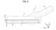
- a wire delivery device 1 (see FIG. 3) according to the first embodiment is a device for delivering a guide wire as an example of a wire.
- a guide wire is used, for example, to be advanced to a surgical site in a body cavity such as a blood vessel, and to penetrate an obstruction in the surgical site.
- the wire delivery device 1 is used by connecting a catheter into which a guide wire is inserted.
- FIG. 1 is a diagram illustrating a guide wire and a catheter connected to a wire delivery device according to the first embodiment, and a connector for connecting to the wire delivery device, and FIG. 2 shows their connection state.
- FIG. 4 is a diagram showing;
- a guide wire GW is inserted into a hollow catheter 51 .
- a catheter hub 52 for adjusting its orientation is non-rotatably mounted on the proximal end side of the catheter 51 .
- the left side of the drawing is the inside of the patient's body (distal side), and the right side of the drawing is the outside of the patient's body (base end).
- the catheter 51 is connected to a connector 60 as shown in FIG. 2 and connected to the wire delivery device 1 via the connector 60 .
- the connector 60 as shown in FIG. 1B, has a dial portion 60A, a mounting portion 60C, and a rear end portion 60D.
- the dial part 60A is a part for operating the direction of the catheter 51 connected to the connector 60 by the operator.
- the attachment portion 60C is formed in a cylindrical shape and is a portion for attachment to a connector connection portion 3 (see FIG. 3) of the wire feeding device 1, which will be described later.
- the length of the mounting portion 60C in the axial direction is substantially the same as the width in the X-axis direction of connecting pieces 3A and 3B of the connector connecting portion 3, which will be described later.
- the rear end portion 60D is formed in a disc shape with a diameter larger than the cylinder of the mounting portion 60C.
- the rear end portion 60 ⁇ /b>D acts to position the connector 60 in the X-axis direction with respect to the connector connection
- a through hole 60B extending in the longitudinal direction is formed in the connector 60 .
- Throughbore 60B is configured to engage rear end 52A of catheter hub 52 .
- FIG. 3 is a perspective view of the wire delivery device
- FIG. 4 is a perspective view of the wire delivery device to which the guidewire and catheter are connected.
- the wire feeding device 1 includes a housing 2 , a lever 31 , a connector connecting portion 3 , a guide wire housing portion 4 and a grasping portion 20 .
- the housing 2 has a substantially rectangular parallelepiped shape extending in the axial direction (the X-axis direction in the drawing) when the guide wire GW is attached.
- the housing 2 includes, in addition to the grasping part 20, various components described later for grasping and delivering the guide wire GW.
- the lever 31 is rotatable about a lever rotation shaft 31O, which will be described later, and is a part operated by the operator when feeding the guide wire GW. In this embodiment, the operator can deliver the guide wire GW by gripping and rotating the lever 31 with one hand.
- the connector connection portion 3 is a portion for connecting the attachment portion 60C of the connector 60, and has a pair of connection pieces 3A and 3B extending in the X-axis direction.
- the connection pieces 3A and 3B are made of, for example, an elastic material such as resin, and sandwich the outer peripheral surface of the mounting portion 60C from both sides in the Y-axis direction to connect the connector 60 in a rotatable manner.
- the guide wire housing portion 4 is a portion that houses the guide wire GW to be delivered, extends in the X-axis direction, and is formed in a concave shape that is open in the positive direction of the Z-axis over the entire X-axis direction.
- the grasping portion 20 is a portion capable of grasping the guide wire GW and movable in the X-axis direction. ) is open to the outside.
- the guide wire GW is placed on the surface of the guide wire accommodating portion 4 in the negative direction of the Z axis (here, also referred to as the bottom surface)
- the guide wire GW is placed on the gripping surface portion 21A and the gripping surface portion 22A of the gripping portion 20. is held (arranged) in the gap (arrangement space) between the
- the guide wire GW at the base end side of the connector 60 is placed on the bottom surface of the concave portion of the guide wire housing portion 4. Then, the attachment portion 60C connected to the catheter 51 into which the guide wire GW is inserted is fitted into the connection pieces 3A and 3B to be attached.
- the catheter 51 and the guide wire GW are connected to the wire delivery device 1 in this way, it becomes as shown in FIG.
- the operator can easily adjust the orientation of the catheter 51 by rotating the operation dial 60A.
- a gap is secured between the surface of the rear end portion 60D on the negative direction side of the X axis (the direction opposite to the direction of the arrow of the X axis) and the surface of the housing 2 on the positive direction side of the X axis. Since the catheter 51 is in such a state that the liquid such as blood or medicinal liquid has passed through the catheter 51, it is easy to flow down from the gap, and the structure on the side of the housing 2 can be properly prevented from coming into contact with the liquid. Further, when the lever 31 is in the initial state, the guide wire GW is not gripped as will be described later, so the direction can be adjusted by turning the guide wire GW.
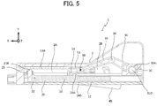
- FIG. 5 is a top cross-sectional view of the wire feeding device in its initial state, and the wire feeding device 1 includes a housing, a grip portion, a compression spring, a slider, a hook, and an ejection switch.
- 6 is a configuration diagram of the grip
- FIG. 7 is an enlarged view of part of the grip
- FIG. 8 is a bottom perspective view of the wire feeding device in its initial state
- FIG. 9 is an injection switch.
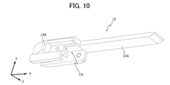
- 10 is a perspective view of a slider
- FIG. 11 is a perspective view of a hook.
- FIG. 7 is an enlarged view of a portion of the grip portion excluding the cylindrical portion.
- FIG. 8 shows a state in which a part of the housing 2 on the negative direction side of the Z-axis is removed from the wire feeding device 1 .
- the bottom perspective views of other drawings in this specification may show the same state.
- the wire feeding device 1 includes a housing 2, a grip portion 20, a compression spring 12, a slider 13, a hook 14, and an ejection switch 45.
- the compression spring 12 is an example of an elastic body.
- the slider 13 and hook 14 are examples of the biasing portion.
- the wire feeding device 1 further includes a lever 31, links 35 and 37, and joints 36 and 38 shown in FIG.
- the lever 31, the links 35, 37, the joints 36, 38, and the slider 13 are examples of the power transmission mechanism
- the slider 13, the hook 14, and the ejection switch 45 are examples of the release portion.
- the housing 2 includes a grip portion accommodating portion 2A that accommodates the grip portion 20 so as to be movable in the X-axis direction, and a slider accommodation portion that accommodates the slider 13 and the hook 14 so as to be movable in the X-axis direction. Part 2B and are formed.
- the housing 2 is formed with a support hole 2C that rotatably supports the cylindrical portion 35A on the one end side of the link 35 .
- the grip portion 20 is movable in the X-axis direction in the grip portion accommodating portion 2A.
- the grasping part 20 can grasp the guide wire GW.
- the gripping portion 20 has a first part 21, a second part 22, a gripping spring 23, and a cylindrical portion 24, as shown in FIG.
- the cylindrical part 24 is a cylindrical part that is connected to the first part 22 in the negative direction of the X axis and extends in the negative direction of the X axis.
- a convex portion 24A is formed on the cylindrical portion 24 on the side of the slider accommodating portion 2B.
- the convex portion 24A can be engaged with the spring hook 14A of the hook 14.
- the cylindrical portion 24 has a stepped portion 24B having a reduced outer diameter in the intermediate portion.
- a compression spring 12 is attached to the stepped portion 24B in the negative direction of the X axis.
- the portion of the compression spring 12 in the positive direction of the X axis contacts the surface of the stepped portion 24B in the negative direction of the X axis, and is located on the outer peripheral side of the portion in the negative direction of the X axis relative to the stepped portion 24B.
- a compression spring 12 is arranged as follows. With such a configuration, when the compression spring 12 is compressed, it is possible to appropriately prevent the compression spring 12 from bending in the X-axis direction and being compressed by the portion of the cylindrical portion 24 on the inner peripheral side.
- the compression spring 12 is, for example, a metal spring, is deformable (compressible) in the X-axis direction, and can apply a biasing force in the positive direction of the X-axis to the grip portion 20 . be.
- the first component 21 has, for example, a grip surface portion 21A formed extending in the X-axis direction and a substantially cylindrical leg portion 21B extending in the Y-axis direction.
- the second part 22 is formed extending in the X-axis direction, and has a gripping surface portion 22A facing the gripping surface portion 21A, concave portions 22B provided in both directions of the Z-axis direction, and through holes into which the leg portions 21B can be inserted. 22C and
- the first component 21 and the second component 22 are combined with the leg portion 21B inserted into the through hole of the through hole portion 22C.
- a gripping spring 23 is attached between the leg portion 21B and the second component 22, and the biasing force of the gripping spring 23 is applied to the surface (gripping surface) of the gripping surface portion 21A on the second component 22 side and the second component 22 side. It acts so that the surface (gripping surface) of the gripping surface portion 22A of 22 on the side of the first component 21 (gripping surface) approaches.
- the gripping surface of the gripping surface portion 21A on the side of the second component 22 and the gripping surface of the gripping surface portion 22A on the side of the first component 21 are separated, and a space (arrangement) is formed between them.
- the guide wire GW can be placed in the space, and then the grasping part 20 can grasp the guide wire GW by the biasing force of the grasping spring 23 .
- This arrangement space can be opened to the outside by an opening extending over the entire movable direction of the grip part 20 .
- the guide wire GW in the concave portion of the guide wire accommodating portion 4, it is guided substantially in the center in the Z-axis direction between the gripping surface of the gripping surface portion 21A and the gripping surface of the gripping surface portion 22A.
- a wire GW can be positioned.
- the leg portion 21B is pushed toward the first component 21 (negative direction of the Y axis) and the gripping spring 23 is compressed, the gripping surface of the gripping surface portion 21A and the gripping surface of the gripping surface portion 22A are brought into contact with each other. Since a space is created by separating them, the guide wire GW is no longer gripped by the gripping part 20 (grip release).
- the concave portion 22B engages with a convex portion (not shown) formed extending in the X-axis direction on both walls in the Z-axis direction of the grip portion accommodating portion 2A, thereby accurately guiding the grip portion 20 in the X-axis direction. act to
- the injection switch 45 has a convex portion 45A, an extension piece 45B, a convex portion 45C, a fixing hole 45D and a spring accommodation portion 45E.
- the convex portion 45A can come into contact with the convex portion 14B (see FIGS. 11 and 13) of the hook 14 and push up the convex portion 14B.
- the extension piece 45B is formed extending in the positive direction of the Y-axis.
- the convex portion 45C is formed at the tip of the extension piece 45B in the positive direction of the Y axis and protrudes in the negative direction of the Z axis.
- the convex portion 45C engages with the convex portion 13B (see FIGS.
- the fixing hole 45D is a hole into which a screw 46 for fixing the ejection switch 45 to the housing 2 so as to be rotatable is inserted.
- the ejection switch 45 is fixed to the housing 2 by screws 46, so that it can rotate around the fixing hole 45D.
- a spring (not shown) that biases the ejection switch 45 in the negative direction of the Y-axis is accommodated in the spring accommodating portion 45E. It should be noted that the injection switch 45 itself may be configured to have elasticity and be biased in the negative direction of the Y-axis without being provided with a spring.
- the slider 13 has an extension 13A extending in the positive direction of the X axis, a projection 13B engageable with the extension piece 45B and the projection 45C of the injection switch 45, and a hook 14. and a mounting portion 13C.
- the extended portion 13A has a plate-like shape with a surface in the negative direction of the Y-axis on the tip end side in the X-axis direction and having a slope such that the thickness becomes thinner toward the tip end side.
- the extension portion 13A is in a state of pushing down the leg portion 21B of the grip portion 20 in the negative direction of the Y-axis.
- the gripping spring 23 is compressed to move the leg portion 21B of the gripping portion 20 in the negative direction of the Y axis.
- the surface of the gripping surface portion 21A on the side of the second component 22 and the surface of the gripping surface portion 22A on the side of the first component 21 are separated, so that the grip of the guide wire GW is released.
- the hook 14 is attached to the attachment portion 13C of the slider.
- the hook 14, as shown in FIG. 11, has a spring hook 14A and a projection 14B.
- the spring hook 14A is engageable with the convex portion 24A of the grip portion 20.
- the convex portion 14B is a portion that contacts the convex portion 45A of the ejection switch 45.
- the hook 14 is elastically deformed, and the spring hook 14A is moved in the same direction.
- the slider 13 and the hook 14 are configured separately, but they may be integrated.
- the lever 31, the links 35, 37, the joints 36, 38, and the slider 13 constitute a power transmission mechanism.
- the lever 31 is a part that is manually rotated by the operator using the wire feeding device 1 .
- the lever 31 is rotatable around a lever rotation shaft 31O.
- the lever 31 and the cylindrical portion 35A of the link 35 are connected via a joint (not shown) so that the turning force can be transmitted from the lever 31 to the link 35.
- the link 35 is configured to rotate together with the rotation of the lever 31 .
- the other end of the link 35 and one end of the link 37 are rotatably connected via a joint 36 .
- the other end of the link 37 and the slider 13 are rotatably connected via a joint 38 .
- the slider 13 is linearly movable in the X-axis direction.
- the power transmission mechanism when the lever 31 is rotated in the R1 direction, the link 35 is rotated in the R2 direction. Move with movement.
- the power transmission mechanism is configured so that the lever 31 can be rotated over the entire range of movement in the X-axis direction, and the links 35 and 37 can be rotated. The length of is adjusted.
- the spring hook 14A engages with the convex portion 24A of the grip portion 20, and when it moves further, the grip portion 20 moves toward the proximal end. side to compress the push spring 12 .
- the projection 45C of the injection switch 45 rides over the projection 13B of the slider 13 in the positive direction of the X axis and engages with each other. As a result, the slider 13 cannot move in the positive direction of the X-axis while the push spring 12 is compressed.
- the convex portion 45A pushes the convex portion 14B in the positive direction of the Y axis, and the portion of the hook 14 on the positive side of the X axis is moved in the positive direction of the Y axis. It is deformed in the positive direction, and the engagement between the spring hook 14A and the convex portion 24A is released. As a result, the deformed state (compressed state) of the compression spring 12 is released at once, and the compression spring 12 pushes the grip portion 20 in the X-axis direction. Since the pressing spring 12 is in contact with the gripping portion 20 , the biasing force of the pressing spring 12 directly acts on the gripping portion 20 .
- FIG. 12 is a top cross-sectional view of the wire feeding device in a ready-to-feed state
- FIG. 13 is a bottom view thereof
- FIG. 14 is a bottom view during feeding
- FIG. 15 is a top cross-sectional view thereof
- FIG. 16 is a top cross-sectional view after delivery.
- the wire feeding device 1 operates in this order to grasp the guide wire GW, move the grasping portion 20 toward the distal end of the guide wire GW, release the grasp of the guide wire GW, and move the grasping portion 20 toward the rear end.
- the grip portion 20, the slider 13, and the hook 14 are configured to be interlocked.
- the guide wire GW is advanced along the blood vessel to the occlusion site.
- the catheter 51 is advanced to the site of obstruction using the guide wire GW as a guide.
- the connector 60 is connected to the catheter hub 52 of the catheter 51 , and the proximal end side of the guide wire GW is inserted into the guide wire accommodating portion 4 of the housing 2 while pushing the connector 60 into the connector connection portion 3 from the positive direction of the Z axis.
- the connector 60 is connected to the wire feeding device 1 by retracting from the positive side of the Z axis.
- the leg portion 21B is pressed in the negative direction of the Y axis by the extension portion 13A, and the gripping spring 23 is compressed. Then, the surface of the gripping surface portion 22A on the side of the first component 21 is separated to form an arrangement space, and the gripping of the guide wire GW by the gripping portion 20 is released. Therefore, as described above, by mounting the catheter 51 into which the guide wire GW has been inserted, the guide wire GW can be easily housed in the installation space. Therefore, the preparation time for delivering the guide wire GW by the wire delivery device 1 can be shortened, and the burden on the patient and operator can be reduced.
- the slider 13 and the hook 14 are slid to the base end side, and as shown in FIG. As the slider 13 moves, the grasping portion 20 moves to the base end side and the compression spring 12 is compressed.
- the slider 13 and the hook 14 slide further to the proximal side, as shown in FIG. , the convex portion 45C of the injection switch 45 climbs over the convex portion 13B of the slider 13 and is positioned in the positive direction of the X axis of the convex portion 13B, and they are engaged with each other.
- the slider 13 cannot move in the positive direction of the X axis, and the compression spring 12 is maintained in a compressed state, so that a state in which delivery is possible (a state in which compression is maintained: a state in which delivery is possible) is achieved.
- the leg portion 21B is pressed in the negative direction of the Y axis by the extension portion 13A, and the gripping spring 23 is compressed. Then, the surface of the gripping surface portion 22A on the side of the first component 21 is separated, and the gripping of the guide wire GW by the gripping portion 20 is released.
- the biasing force of the push spring 12 is applied to move the gripping portion 20 in the distal direction at once, and the gripping portion 20 moves in the distal direction and stops at the distal end position of the gripping portion 20 .
- the extension portion 13A does not come into contact with the leg portion 21B and does not compress the gripping spring 23.
- the guide wire GW is gripped between the surface on the side of the second component 22 and the surface of the grip surface portion 22A on the side of the first component 21 .
- the guide wire GW is maintained in a gripped state from the time it is gripped by the gripping portion 20 until the gripping portion 20 moves to the most distal position.
- the guide wire GW is delivered to the distal end side by a distance D from the position where it is gripped by the gripping part 20 until the gripping part 20 reaches the distal end position. This distance D corresponds to the wire feeding amount by the wire feeding device 1 at one time.
- the lever 31 can be rotated in the same manner as described above and the same operation can be performed.
- the wire feeding device 1 it is possible to apply the urging force accumulated in the compression spring 12 to the guide wire GW to feed out an appropriate amount. Since the biasing force can be applied to the guidewire GW in this manner, the obstruction can be penetrated more effectively by the guidewire GW.
- FIG. 17 is a top view of the wire feeding device in the initial state according to the second embodiment
- FIG. 18 is a top cross-sectional view of the wire feeding device in the initial state
- FIG. 19 is a wire feeding device in the initial state
- Figure 20 is a side view and Figure 20 is a perspective view of the slider of the wire delivery device; Parts similar to those of the wire feeding device 1 according to the first embodiment are denoted by the same reference numerals, and overlapping descriptions are omitted.
- the wire feeding device 201 includes a gripping portion 220 instead of the gripping portion 20, a slider 210 instead of the slider 13, and an adjusting portion 240 in the housing 2. As shown in FIG. 20, the slider 210 does not have the extended portion 13A of the slider 13. As shown in FIG. Parts of the slider 210 that are common to the slider 13 are given the same reference numerals.
- FIG. 21 is an exploded perspective view of a portion of the gripping portion
- FIG. 22 is a perspective view of a portion of the gripping portion in a grip-released state
- FIG. 23 is a side sectional view of the grip-released state
- 24 is a perspective view of the gripped state
- FIG. 25 is a side sectional view of the gripped state.
- the gripping portion 220 has the gripping portion 20 and the cylindrical portion 24 in common, and the other configurations are different. However, in FIGS. 21 to 25, illustration of the cylindrical portion 24 is omitted.
- the gripping portion 220 includes a body portion 221 as an example of a first gripping portion, a facing component 222 as an example of a second gripping portion, a cam portion 223, a grip release spring 224, a support pin 225, and a retaining ring 226. and have
- the body portion 221 has a gripping surface 221A and a wall portion 221B.
- the grip surface 221A is a surface in the negative direction of the Y axis that grips the guide wire GW, and for example, a rubber member may be attached to this surface.
- the gripping surface 221A has a surface that intersects the movable direction (X-axis direction) of the gripping portion 220 .
- the wall portion 221B has a hole 221C into which a support pin 225 that rotatably supports the cam portion 223 is inserted, and a hole 221D into which a support pin 225 that rotatably supports the opposing component 222 is inserted.
- the cam portion 223 has an operation convex portion 223A, a through hole 223B, and a contact surface 223C.
- the operation convex portion 223A is provided on the side surface of the cam portion 223 and is a portion for operating the state of the cam portion 223 .
- the through hole 223B is a hole into which a pin 225 for rotationally supporting the cam portion 223 is inserted.
- 223 C of contact surfaces are surfaces which contact the surface of the positive direction of the Y-axis of the opposing component 222. As shown in FIG.
- a cross-sectional shape (the same shape as the side surface) of the contact surface 223C on a plane perpendicular to the X axis has a linear portion 223D and a curved portion 223E.
- the cam portion 223 can be maintained in a state in which the grip portion 220 grips the guide wire GW.
- the facing component 222 has a gripping surface 222A and a through hole 222B.
- the gripping surface 222A is a surface in the positive direction of the Y-axis that grips the guide wire GW, and has a surface shape corresponding to the gripping surface 221A of the main body 221 .
- a rubber member may be attached to the grip surface 222A.
- the through-hole 222B is a hole into which a pin 225 is inserted to support rotation of the opposing component 222. As shown in FIG.
- the grip releasing spring 224 is biased and arranged so that the distance between the facing surfaces of the main body portion 221 and the facing component 222 widens.
- the grip release spring 224 is set so that the cam portion 223 and the opposing component 222 are positioned in the positive direction of the Z axis relative to the maximum outer shape portion 223F. , or the linear portion 223D, the gap between the opposing surfaces of the main body portion 221 and the opposing component 222 is widened.
- the support pin 225 is a columnar member having a head portion 225A at a first end and a groove portion 225B into which a snap ring 226 is fitted at a second end opposite to the first end. .
- the snap ring 226 prevents the support pin 225 from falling out of the holes 221C and 221D by being attached to the groove 225B of the support pin 225.
- the support pin 225 is inserted into the hole 221D in the negative direction of the X axis, the through hole 222B of the opposing part 222, and the positive direction of the X axis of the body portion 221.
- the retaining ring 226 is attached to the groove 225B of the support pin 225 .
- the support pin 225 is inserted into the hole 221C of the body portion 221 in the negative direction of the X axis, the through hole 223B of the cam portion 223, and the hole 221C of the body portion 221 in the positive direction of the X axis.
- a retaining ring 226 is attached to the .
- the grip portion 220 shown in FIG. 22 is completed.
- the grasping part 220 is in a state in which the grip of the guide wire GW is released (grip release state).
- the gripping portion 220 is such that the linear portion 223D of the contact surface 223C of the cam portion 223 is in contact with the surface of the corresponding component 222 in the positive direction of the Y axis, and the gripping surface 222A is in contact. and the grip surface 221A are separated from each other.
- the gripping portion 220 is in contact with the surface of the corresponding component 222 in the positive Y-axis direction at a position in the negative direction of the Z-axis rather than the maximum outer shape portion 223F, and the gripping surface 222A is in contact with the gripping surface 222A. and the grip surface 221A are in contact with each other. Since the distance from the rotation axis of the cam portion 223 is longer than the contact position, the maximum outer shape portion 223F suppresses the movement of the cam portion 223 in the direction opposite to the R3 direction. 222A and the gripping surface 221A are kept in contact with each other.
- the adjustment portion 240 is a substantially plate-shaped member, and as shown in FIG. 19, is arranged in a range that includes the moving range in the X-axis direction of the operation convex portion 223A on the positive direction side of the Y-axis of the grip portion 220. .
- the adjustment portion 240 has an adjustment frame 240A that can adjust the position of the operation convex portion 223A.
- the adjustment frame 240A guides the operation convex portion 223A as indicated by the arrow D1, and the grip portion 20 is moved to the position in the most negative direction of the X axis.
- the operation convex portion 223A is guided to a position in the negative direction of the Z axis, that is, a position where the grip portion 20 grips the guide wire GW.
- the adjusting frame 240A guides the guide convex portion 223A as indicated by the arrow D2, and the gripping portion 20 moves to the position in the most positive direction of the X axis.
- the operation convex portion 223A guides to the position in the positive direction of the Z axis, that is, the position where the grasping portion 20 releases the grip of the guide wire GW.
- the adjustment frame 240A has a rhombic shape whose apex is the position where the grip portion 20 grips or releases the guide wire GW, that is, the position where the operation convex portion 223A stops. It's becoming
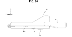
- FIG. 26 is a top view of the wire feeding device in a ready-to-deliver state
- FIG. 27 is a cross-sectional top view in the ready-to-delivery state
- FIG. 28 is a side view thereof. 26 to 28, the guide wire GW, catheter 51, connector 60, etc. are not shown, but the catheter 51 and connector 60 are connected to the wire delivery device 201. Subsequent processing will be described.
- the wire delivery device 201 operates in this order to grasp the guide wire GW, move the grasping portion 220 toward the distal end of the guide wire GW, release the grasp of the guide wire GW, and move the grasping portion 220 toward the rear end.
- the grip portion 220 and the slider 210 are configured to be interlocked.
- the operation convex portion 223A of the grip portion 220 is guided by the adjustment frame 240A of the adjustment portion 240 to the position where the grip of the grip portion 220 is released. , the grip surface 222A and the grip surface 221A are separated from each other, and the grip of the guide wire GW by the grip portion 220 is released.
- the slider 13 and the hook 14 are moved to the proximal side. 27 and 28, the projecting portion 45C of the extension piece 45B of the injection switch 45 overcomes the projecting portion 13B of the slider 210 and is positioned in the positive direction of the X axis of the projecting portion 13B. and engage each other. As a result, the slider 13 cannot move in the positive direction of the X axis, and the compression spring 12 is maintained in a compressed state, so that a state in which delivery is possible (a state in which compression is maintained: a state in which delivery is possible) is achieved.
- the adjustment frame 240A of the adjustment portion 240 guides the operation convex portion 223A to a position where the grip portion 220 is gripped, so that the guide wire GW is gripped between the grip surface 222A and the grip surface 221A. It will happen.
- the convex portion 45A pushes the convex portion 14B of the hook 14 in the positive direction of the Y axis, as in the case shown in FIG.
- the spring hook 14A moves in the positive direction of the Y-axis as in the case shown in FIG.
- the convex portion 45C of the ejection switch 45 moves in the positive direction from the surface of the slider 210 in the positive direction of the Y axis and is no longer engaged with the convex portion 13B of the slider 210, and the slider 210 moves in the positive direction of the X axis. becomes movable.
- the biasing force of the push spring 12 is applied to the movement of the grasping portion 220 in the distal direction at once, and the grasping portion 220 that grasps the guide wire GW moves in the distal direction and stops at the distal end position.
- the operation convex portion 223A is guided by the adjustment frame 240A to the position where the gripping of the gripping portion 220 is released, so that the gripping portion 220 is able to grip the guide wire GW. release.
- the grasping part 220 moves while maintaining the state of grasping the guide wire GW from the rearmost position to before reaching the most distal position.
- the guide wire GW is delivered to the distal side by the distance from the rear end position of the gripping portion 220 to the position where the gripping of the gripping portion 220 is released.
- the slider 210 moves in the positive direction of the X axis, and the wire feeding device 201 can be returned to the initial state shown in FIG. If the guide wire GW needs to be delivered continuously, the lever 31 can be rotated in the same manner as described above and the same operation can be performed.
- the wire feeding device 201 it is possible to apply the urging force accumulated in the compression spring 12 to the guide wire GW and feed the guide wire GW in an appropriate amount. Since the biasing force of the compression spring 12 can be applied to the guide wire GW in this manner, the obstruction can be effectively penetrated by the guide wire GW.
- a metal spring is used as the compression spring 12, but other types of elastic bodies such as rubber cords and leaf springs may be used. It can be material.
- An elastic body may be provided so as to extend against the movement of the body, and the extension of the elastic body may increase the biasing force.
- a mechanism for adjusting the movable range of the gripping parts 20 and 220 in the X-axis direction for example, a mechanism for moving the position of the wall in the X-axis direction that determines the movable range may be provided. With this configuration, the amount of wire fed by the wire feeding device can be adjusted easily and appropriately.
- a mechanism for adjusting the amount of compression of the compression spring 12 in the initial state for example, a mechanism for moving the position of the wall on the proximal end side of the compression spring 12 may be provided. By doing so, it is possible to easily and appropriately adjust the urging force applied to the gripping portions 20 and 220 in the wire feeding device.
- the guide wire GW is delivered by the operator manually turning the lever 31, it may be delivered by a motor operated by electric power.
- the link 35 may be rotated by power of a motor.
- the motor may be stopped when the link 35 is rotated by a predetermined angle.
- a switch for driving the motor may be provided, and when the switch is pressed once, the motor may be driven to rotate the link 35 by a predetermined angle.
- Wire feeding device (first embodiment) 2 Housing 2A Grasping Part Accommodating Part 2B Slider Accommodating Part 2C Support Hole 3 Connector Connecting Part 3A, 3B Connecting Piece 4 Guide Wire Accommodating Part 12 Pushing Spring 13 Slider 13A Extension 13B Projection 13C Mounting Part 14 Hook 14A Spring Hook 14B Convex portion 20 Grip portion 21 First component 21A Grip surface portion 21B Leg portion 22 Second component 22A Grip surface portion 22B Concave portion 22C Through hole 23 Grip spring 24 Cylindrical portion 24A Convex portion 24B Stepped portion 31 Lever 31O Lever rotating shaft 35,37 Link 35A Cylindrical portion 36, 38 Joint 45 Injection switch 45A Convex portion 45B Extension piece 45C Convex portion 45D Fixing hole 45E Spring housing portion 46 Screw 51 Catheter 52 Catheter hub 52A Rear end portion 60 Connector 60A Dial portion 60B Through hole 60C Mounting portion 60D Rear end part 201 wire feeding device (second embodiment) 210 slider 2
Landscapes
- Health & Medical Sciences (AREA)
- Life Sciences & Earth Sciences (AREA)
- Biophysics (AREA)
- Pulmonology (AREA)
- Engineering & Computer Science (AREA)
- Anesthesiology (AREA)
- Biomedical Technology (AREA)
- Heart & Thoracic Surgery (AREA)
- Hematology (AREA)
- Animal Behavior & Ethology (AREA)
- General Health & Medical Sciences (AREA)
- Public Health (AREA)
- Veterinary Medicine (AREA)
- Media Introduction/Drainage Providing Device (AREA)
Priority Applications (2)
| Application Number | Priority Date | Filing Date | Title |
|---|---|---|---|
| PCT/JP2021/016083 WO2022224360A1 (ja) | 2021-04-20 | 2021-04-20 | ワイヤ送出装置 |
| JP2023515937A JPWO2022224360A1 (https=) | 2021-04-20 | 2021-04-20 |
Applications Claiming Priority (1)
| Application Number | Priority Date | Filing Date | Title |
|---|---|---|---|
| PCT/JP2021/016083 WO2022224360A1 (ja) | 2021-04-20 | 2021-04-20 | ワイヤ送出装置 |
Publications (1)
| Publication Number | Publication Date |
|---|---|
| WO2022224360A1 true WO2022224360A1 (ja) | 2022-10-27 |
Family
ID=83722096
Family Applications (1)
| Application Number | Title | Priority Date | Filing Date |
|---|---|---|---|
| PCT/JP2021/016083 Ceased WO2022224360A1 (ja) | 2021-04-20 | 2021-04-20 | ワイヤ送出装置 |
Country Status (2)
| Country | Link |
|---|---|
| JP (1) | JPWO2022224360A1 (https=) |
| WO (1) | WO2022224360A1 (https=) |
Citations (4)
| Publication number | Priority date | Publication date | Assignee | Title |
|---|---|---|---|---|
| US5749371A (en) * | 1995-10-06 | 1998-05-12 | Zadini; Filiberto P. | Automatic guidewire placement device for medical catheters |
| JP2015510830A (ja) * | 2012-03-18 | 2015-04-13 | トラウマテック ソリューションズ ベー.フェー. | 血管内アクセスおよび治療のためのデバイスおよび方法 |
| US20160375223A1 (en) * | 2015-06-23 | 2016-12-29 | Traumatek Solutions, B.V. | Vessel cannulation device and method of use |
| JP2018064822A (ja) * | 2016-10-20 | 2018-04-26 | 株式会社ハイレックスコーポレーション | ガイドワイヤ操作具および該ガイドワイヤ操作具を備えたガイドワイヤのセット |
-
2021
- 2021-04-20 JP JP2023515937A patent/JPWO2022224360A1/ja active Pending
- 2021-04-20 WO PCT/JP2021/016083 patent/WO2022224360A1/ja not_active Ceased
Patent Citations (4)
| Publication number | Priority date | Publication date | Assignee | Title |
|---|---|---|---|---|
| US5749371A (en) * | 1995-10-06 | 1998-05-12 | Zadini; Filiberto P. | Automatic guidewire placement device for medical catheters |
| JP2015510830A (ja) * | 2012-03-18 | 2015-04-13 | トラウマテック ソリューションズ ベー.フェー. | 血管内アクセスおよび治療のためのデバイスおよび方法 |
| US20160375223A1 (en) * | 2015-06-23 | 2016-12-29 | Traumatek Solutions, B.V. | Vessel cannulation device and method of use |
| JP2018064822A (ja) * | 2016-10-20 | 2018-04-26 | 株式会社ハイレックスコーポレーション | ガイドワイヤ操作具および該ガイドワイヤ操作具を備えたガイドワイヤのセット |
Also Published As
| Publication number | Publication date |
|---|---|
| JPWO2022224360A1 (https=) | 2022-10-27 |
Similar Documents
| Publication | Publication Date | Title |
|---|---|---|
| CN111132623B (zh) | 用于夹具施放器的钳口 | |
| EP3546009B1 (en) | Steerable catheter suitable for left-hand operation | |
| KR101832511B1 (ko) | 스크류 전달 시스템 | |
| JP4198435B2 (ja) | 歯科治療麻酔薬用電動注射器 | |
| KR20170101829A (ko) | 트랜스미션 메커니즘, 특히 기어 트레인을 구비한 인젝터 | |
| CN111249630B (zh) | 口腔压舌支架 | |
| EP1800624B1 (en) | Spring-biased injector for an intraocular lens | |
| EP2083715B1 (en) | Removable handle for medical device | |
| WO2024245226A1 (zh) | 穿刺锁定装置及缝合设备 | |
| JP7250947B2 (ja) | ワイヤ送出装置 | |
| WO2022224360A1 (ja) | ワイヤ送出装置 | |
| US20240032959A1 (en) | Wire feeding device | |
| CN102665578A (zh) | 囊捕获勒除器 | |
| WO2024075199A1 (ja) | ワイヤ送出装置 | |
| CN219331585U (zh) | 内窥镜先端部用角度调节装置 | |
| EP4647032A1 (en) | Holding controller | |
| JP7369589B2 (ja) | ワイヤ送出装置 | |
| JP2010178988A (ja) | 医療装置 | |
| JP2003038427A (ja) | 内視鏡鉗子口用アダプタ | |
| CN222383133U (zh) | 操作手柄、内窥镜以及手术机器人 | |
| CN118303816B (zh) | 一种器械引导件和内窥镜及其使用方法 | |
| JP2000166863A (ja) | 内視鏡用穿刺具 | |
| CN219184490U (zh) | 一种眼内植入物植入装置 | |
| US20250312556A1 (en) | Catheter assembly for regional anaesthesia | |
| JP2025171500A (ja) | ガイドワイヤ操作器具 |
Legal Events
| Date | Code | Title | Description |
|---|---|---|---|
| 121 | Ep: the epo has been informed by wipo that ep was designated in this application |
Ref document number: 21937856 Country of ref document: EP Kind code of ref document: A1 |
|
| WWE | Wipo information: entry into national phase |
Ref document number: 2023515937 Country of ref document: JP |
|
| NENP | Non-entry into the national phase |
Ref country code: DE |
|
| 122 | Ep: pct application non-entry in european phase |
Ref document number: 21937856 Country of ref document: EP Kind code of ref document: A1 |