WO2022224305A1 - 磁気熱交換器および空調換気システム - Google Patents
磁気熱交換器および空調換気システム Download PDFInfo
- Publication number
- WO2022224305A1 WO2022224305A1 PCT/JP2021/015866 JP2021015866W WO2022224305A1 WO 2022224305 A1 WO2022224305 A1 WO 2022224305A1 JP 2021015866 W JP2021015866 W JP 2021015866W WO 2022224305 A1 WO2022224305 A1 WO 2022224305A1
- Authority
- WO
- WIPO (PCT)
- Prior art keywords
- space
- magnetic
- heat exchange
- exchange chamber
- magnetic field
- Prior art date
- Legal status (The legal status is an assumption and is not a legal conclusion. Google has not performed a legal analysis and makes no representation as to the accuracy of the status listed.)
- Ceased
Links
Images


Classifications
-
- F—MECHANICAL ENGINEERING; LIGHTING; HEATING; WEAPONS; BLASTING
- F24—HEATING; RANGES; VENTILATING
- F24F—AIR-CONDITIONING; AIR-HUMIDIFICATION; VENTILATION; USE OF AIR CURRENTS FOR SCREENING
- F24F7/00—Ventilation
- F24F7/04—Ventilation with ducting systems, e.g. by double walls; with natural circulation
- F24F7/06—Ventilation with ducting systems, e.g. by double walls; with natural circulation with forced air circulation, e.g. by fan positioning of a ventilator in or against a conduit
- F24F7/08—Ventilation with ducting systems, e.g. by double walls; with natural circulation with forced air circulation, e.g. by fan positioning of a ventilator in or against a conduit with separate ducts for supplied and exhausted air with provisions for reversal of the input and output systems
-
- F—MECHANICAL ENGINEERING; LIGHTING; HEATING; WEAPONS; BLASTING
- F25—REFRIGERATION OR COOLING; COMBINED HEATING AND REFRIGERATION SYSTEMS; HEAT PUMP SYSTEMS; MANUFACTURE OR STORAGE OF ICE; LIQUEFACTION SOLIDIFICATION OF GASES
- F25B—REFRIGERATION MACHINES, PLANTS OR SYSTEMS; COMBINED HEATING AND REFRIGERATION SYSTEMS; HEAT PUMP SYSTEMS
- F25B21/00—Machines, plants or systems, using electric or magnetic effects
-
- F—MECHANICAL ENGINEERING; LIGHTING; HEATING; WEAPONS; BLASTING
- F28—HEAT EXCHANGE IN GENERAL
- F28D—HEAT-EXCHANGE APPARATUS, NOT PROVIDED FOR IN ANOTHER SUBCLASS, IN WHICH THE HEAT-EXCHANGE MEDIA DO NOT COME INTO DIRECT CONTACT
- F28D11/00—Heat-exchange apparatus employing moving conduits
- F28D11/02—Heat-exchange apparatus employing moving conduits the movement being rotary, e.g. performed by a drum or roller
-
- F—MECHANICAL ENGINEERING; LIGHTING; HEATING; WEAPONS; BLASTING
- F28—HEAT EXCHANGE IN GENERAL
- F28F—DETAILS OF HEAT-EXCHANGE AND HEAT-TRANSFER APPARATUS, OF GENERAL APPLICATION
- F28F21/00—Constructions of heat-exchange apparatus characterised by the selection of particular materials
- F28F21/08—Constructions of heat-exchange apparatus characterised by the selection of particular materials of metal
-
- Y—GENERAL TAGGING OF NEW TECHNOLOGICAL DEVELOPMENTS; GENERAL TAGGING OF CROSS-SECTIONAL TECHNOLOGIES SPANNING OVER SEVERAL SECTIONS OF THE IPC; TECHNICAL SUBJECTS COVERED BY FORMER USPC CROSS-REFERENCE ART COLLECTIONS [XRACs] AND DIGESTS
- Y02—TECHNOLOGIES OR APPLICATIONS FOR MITIGATION OR ADAPTATION AGAINST CLIMATE CHANGE
- Y02B—CLIMATE CHANGE MITIGATION TECHNOLOGIES RELATED TO BUILDINGS, e.g. HOUSING, HOUSE APPLIANCES OR RELATED END-USER APPLICATIONS
- Y02B30/00—Energy efficient heating, ventilation or air conditioning [HVAC]
Definitions
- the present disclosure relates to magnetic heat exchangers and air conditioning ventilation systems.
- a magnetic heat exchanger that uses the magnetocaloric effect of a magnetic material (magnetocaloric material) that absorbs and heats by excitation and demagnetization is known (for example, Patent Document 1).
- the magnetic heat exchanger described in Patent Document 1 includes a plurality of heat transfer areas partitioned by isolation walls and each filled with a heat medium, and a magnetic field generated in each predetermined area within the plurality of heat transfer areas.
- a magnetocaloric material that changes in temperature due to changes in the magnetic field generated by the magnetic field generator and that is configured by inserting an isolation wall between a plurality of adjacent heat transfer regions;
- a rotating part for rotating the magnetocaloric material in the heat medium in the predetermined area of the first heat transfer area and in the heat medium outside the predetermined area of the second heat transfer area.
- a main object of the present disclosure is to provide a magnetic heat exchanger and an air conditioning ventilation system that can improve heat exchange efficiency without increasing the heat transfer area.
- a magnetic heat exchanger has a central axis and includes a first magnetic heat exchange chamber and a second magnetic heat exchange chamber arranged to sandwich the central axis in a radial direction with respect to the central axis; a magnetic field intensity distribution between a drive unit that rotates the heat exchange unit around the central axis and a first space located on one side of the central axis and a second space located on the other side in the radial direction with respect to the central axis; A first magnetic field generating section to be formed, and a case housing the heat exchange section and partitioning the first space and the second space are provided.
- Each of the first magnetic heat exchange chamber and the second magnetic heat exchange chamber includes a space penetrating in the extending direction of the central axis.
- a material forming at least a portion of each of the first magnetic heat exchange chamber and the second magnetic heat exchange chamber includes a magnetocaloric material.
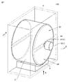
- FIG. 1 is a perspective view for explaining a magnetic heat exchanger according to Embodiment 1;
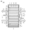
- FIG. 2 is a cross-sectional view as seen from arrow II-II in FIG. 1;
- FIG. FIG. 2 is a partial cross-sectional view of the heat exchange section in FIG. 1 as viewed in a cross section perpendicular to the central axis;
- FIG. 2 is a cross-sectional view showing a usage example of the magnetic heat exchanger according to Embodiment 1;
- FIG. 8 is a perspective view for explaining a magnetic heat exchanger according to Embodiment 2;
- FIG. 11 is a perspective view for explaining a magnetic heat exchanger according to Embodiment 3;
- FIG. 11 is a perspective view for explaining a magnetic heat exchanger according to Embodiment 4;
- FIG. 11 is a diagram for explaining an air-conditioning ventilation system according to Embodiment 5;
- the magnetic heat exchanger 100 according to Embodiment 1 is a magnetic heat exchanger in which heat is exchanged between a magnetocaloric material and a heat transport medium. Specifically, in the magnetic heat exchanger 100, heat exchange is performed between the magnetocaloric material and the first heat transport medium, and heat exchange is performed between the magnetocaloric material and the second heat transport medium. magnetic heat exchanger. As shown in FIGS. 1 and 2, the magnetic heat exchanger 100 includes a driving section 1, a first magnetic field generating section 2, a heat exchanging section 3, and a case 4. FIG.
- the drive unit 1 includes a first rotating shaft 11 and a motor 12 that rotates the first rotating shaft 11 .
- the 1st rotating shaft 11 is extended along the central axis line C of the heat exchange part 3 mentioned later.
- the central axis of the first rotating shaft 11 is arranged coaxially with the central axis C of the heat exchange section 3, for example.
- the extending direction of the central axis C of the heat exchange section 3 is simply referred to as the axial direction.
- a radial direction with respect to the center axis C is simply referred to as a radial direction.
- the circumferential direction with respect to the central axis C is simply called the circumferential direction.
- the axial direction is, for example, along the horizontal direction.
- the rotation speed (the number of rotations per unit time) of the first rotating shaft 11 is not particularly limited. be.
- the drive unit 1 is arranged outside the case 4, for example.
- the first magnetic field generator 2 is positioned between a first space S1 (see FIG. 2) located on one side of the central axis C and a second space S2 (see FIG. 2) located on the other side in the first direction A. form the intensity distribution of the magnetic field.
- the first direction A is a specific direction along the radial direction.
- the first direction A is, for example, the vertical direction.
- the first magnetic field generator 2 is arranged on the one side with respect to the central axis C.
- the distance between the first magnetic field generator 2 and the first space is longer than the distance between the first magnetic field generator 2 and the second space.
- the first magnetic field generator 2 generates a stronger magnetic field in the second space than in the first space.
- the first magnetic field generator 2 is provided to excite the magnetocaloric material that has moved from the first space to the second space and to demagnetize the magnetocaloric material that has moved from the second space to the first space.
- the first magnetic field generating section 2 is provided so as to periodically increase or decrease the strength of the magnetic field with respect to the heat exchanging section 3 rotated around the central axis C by the driving section 1 .
- the first magnetic field generator 2 does not rotate synchronously with the heat exchange section 3 .
- the first magnetic field generator 2 is fixed to, for example, a case 4 which will be described later.
- the first magnetic field generator 2 includes, for example, a permanent magnet as a magnetic force source.
- the magnetic force source of the first magnetic field generator 2 is composed of, for example, a permanent magnet.
- the first magnetic field generator 2 is arranged symmetrically with respect to a plane passing through the central axis C and extending along the first direction A, for example. Note that the first magnetic field generator 2 may be provided in the second space so as to generate a stronger magnetic field as it advances in the direction of rotation.
- the heat exchange section 3 has a central axis C.
- the heat exchange section 3 is fixed to the first rotating shaft 11 and rotated around the central axis C by the driving section 1 .
- the heat exchange section 3 includes a plurality of magnetic heat exchange chambers arranged side by side in the circumferential direction. By rotating the heat exchanging portion 3 in the circumferential direction by the drive portion 1, each of the plurality of magnetic heat exchanging chambers alternately and repeatedly moves inside each of the first space and the second space. In other words, each of the plurality of magnetic heat exchange chambers periodically moves within the space where the intensity distribution of the magnetic field is formed by the first magnetic field generator 2 .
- a space 30 (see FIG. 2) extending along the axial direction is formed in each of the plurality of magnetic heat exchange chambers.
- Each space 30 is provided so as to form a first channel through which the first heat transport medium flows in the axial direction or a second channel through which the second heat transport medium flows in the axial direction. 1, the illustration of the plurality of magnetic heat exchange chambers and the plurality of spaces 30 is omitted.
- the plurality of magnetic heat exchange chambers include a first magnetic heat exchange chamber and a second magnetic heat exchange chamber arranged so as to sandwich the central axis C in the radial direction.
- the first magnetic exchange chamber is arranged 180 degrees rotationally symmetrical to the second magnetic exchange chamber with respect to the central axis C, for example.
- the first magnetic heat exchange chamber is arranged in the first space and the second magnetic heat exchange chamber is arranged in the second space.
- a first state and a second state in which the first magnetic heat exchange chamber is arranged in the second space and the second magnetic heat exchange chamber is arranged in the first space are alternately switched.
- the heat exchange section 3 includes, for example, multiple annular members 31 and multiple corrugated members 32 .
- Each of the plurality of annular members 31 extends along the circumferential direction and is spaced apart from each other in the radial direction.
- Each of the plurality of annular members 31 is arranged concentrically, for example.
- Each of the multiple corrugated members 32 is connected to at least one annular member 31 of the multiple annular members 31 .
- Each of the plurality of corrugated members 32 connects, for example, two radially adjacent annular members 31 .
- Two radially adjacent annular members 31 and one corrugated member 32 arranged therebetween are provided so as to partition a plurality of spaces 30 .
- One space 30 and parts of the annular member 31 and the corrugated member 32 facing the one space 30 constitute one magnetic heat exchange chamber.
- the material that constitutes at least part of each of the plurality of magnetic heat exchange chambers includes a magnetocaloric material.
- the material forming each annular member 31 comprises a magnetocaloric material.
- the magnetocaloric material is a magnetic material that provides a magnetocaloric effect, and includes gadolinium (Gd), for example.
- the material forming the corrugated member 32 does not contain a magnetocaloric material, but only a material that is easier to process (has high ductility) than the magnetocaloric material.
- a material forming the corrugated member 32 includes, for example, aluminum (Al).
- the corrugated member 32 may be made of paper.
- the material that constitutes at least part of each of the plurality of magnetic heat exchange chambers contains a material that absorbs and releases moisture.
- Moisture-absorbing and desorbing materials include, for example, at least one of diatomaceous earth and silica gel.
- the outer shape of the heat exchange section 3 is circular, for example.
- the heat exchange section 3 is rotatably supported around the central axis C by the case 4 .
- the heat exchange section 3 is housed in the case 4 .
- the case 4 includes the first space and the second space as internal spaces.
- the case 4 is arranged so as to sandwich the first space in the axial direction, and a pair of first inlets and outlets (41, 42) are formed. Further, the case 4 is arranged so as to sandwich the second space in the axial direction, and a pair of second inlets and outlets ( 43, 44) are formed. In addition, in FIG. 1, the case 4 is indicated by a dashed line for convenience.
- a pair of first inlets and outlets includes a first inlet 41 for the first heat transport medium to flow into the first space and a first heat transport medium for the first heat transport medium to flow out of the first space. 1 outflow port 42 .
- a pair of second inlets includes a second inlet 43 for the second heat transport medium to flow into the second space and a second heat transport medium for the second heat transport medium to flow out of the second space. 2 outlets 44 .
- the first inlet 41 and the first outlet 42 are provided symmetrically with the heat exchange section 3 interposed therebetween.
- the second inlet 43 and the second outlet 44 are provided symmetrically with the heat exchange section 3 interposed therebetween.
- Each planar shape of the first inlet 41, the first outlet 42, the second inlet 43, and the second outlet 44 is, for example, a substantially semicircular shape.
- the second inlet 43 is arranged on the same side as the first outlet 42 with respect to the heat exchange section 3 in the axial direction.
- the second outlet 44 is arranged on the same side as the first inlet 41 with respect to the heat exchange section 3 in the axial direction.
- the case 4 has, for example, a circular first opening located on the axial side of the driving section 1 and a circular second opening located on the axial side opposite to the driving section 1 . is formed.
- the case 4 includes a first separator 45A that divides the first opening into the first inlet 41 and the second outlet 44, and a second opening into the first outlet 42 and the second inlet 43. and a second separator 45B.
- At least the first separator 45A has a through hole through which the first rotating shaft 11 is passed.
- the second separator 45B is also formed with a through hole through which the first rotating shaft 11 is passed.
- Each of the first separator 45A and the second separator 45B extends along a direction orthogonal to each of the axial direction and the first direction A. As shown in FIG. Both end faces in the axial direction of the heat exchanging portion 3 are parallel to the respective inner peripheral surfaces of the case 4 on which the first opening and the second opening are formed.
- FIG. 4 is a diagram showing a usage example of the magnetic heat exchanger 100.
- the magnetic heat exchanger 100 includes a third space S3 filled with a heat transport medium with a relatively high temperature and a fourth space S3 filled with a heat transport medium with a relatively low temperature. It is arranged in the space connecting S4.
- the first heat transport medium is a heat transport medium that flows from the third space S3 to the fourth space S4.
- the second heat transport medium is a heat transport medium that flows from the fourth space S4 to the third space S3.
- a first flow path and a second flow path that are separated from each other are formed in the space that connects the third space S3 and the fourth space S4.
- the heat transport medium is, but not limited to, air, for example.
- the first flow path includes an upstream flow path F1 through which the first heat transport medium flowing into the first space S1 of the magnetic heat exchanger 100 flows, and the first heat transport medium flowing in from the first space S1 of the magnetic heat exchanger 100. and a downstream flow path F2.
- the upstream flow path F1 is formed between the inlet 51 and the first inlet 41 through which the first heat transport medium flows from the third space S3.
- the downstream flow path F2 is formed between the first outlet 42 and the outlet 52 through which the first heat transport medium flows out to the fourth space S4.
- the second flow path includes an upstream flow path F3 in which the second heat transport medium flowing into the second space S2 of the magnetic heat exchanger 100 flows, and the second heat transport medium flowing in from the second space S2 of the magnetic heat exchanger 100. and a downstream flow path F4.
- the upstream flow path F3 is formed between the inlet 53 and the second inlet 43 through which the second heat transport medium flows from the fourth space S4.
- the downstream flow path F4 is formed between the second outlet 44 and the outlet 54 through which the second heat transport medium flows out to the third space S3.
- the first heat transport medium in the first flow path is sent in a first direction along the axial direction by, for example, a first pump 6 (for example, an air blower) arranged in the downstream flow path F2.
- the second heat transport medium in the second flow path is forced along the axial direction and in a second direction opposite to the first direction by, for example, a second pump 7 (eg, blower) located in the downstream flow path F4. Sent.
- the first magnetic heat exchange chamber is arranged in the first space and the second magnetic heat exchange chamber is arranged in the first space.
- the second state is alternately switched.
- the magnetocaloric material in the first magnetic heat exchange chamber moves from the first space to the second space and is excited by the first magnetic field generator 2 to generate heat.
- the magnetocaloric material in the second magnetic heat exchange chamber is demagnetized and absorbs heat as it moves from the second space to the first space.
- the magnetocaloric material in the first magnetic heat exchange chamber is demagnetized and absorbs heat as it moves from the second space to the first space.
- the magnetocaloric material in the second magnetic heat exchange chamber is excited and generates heat as it moves from the first space to the second space.
- part of the heat quantity of the first heat transport medium that has flowed into the first space from the upstream flow path F1 is recovered (heat stored) in the magnetic heat exchange chamber, and recovered (heat absorbed) by the magnetocaloric material in the heat absorbing state. ), and then flows out to the fourth space S4 via the downstream flow path F2.
- the second heat transport medium that has flowed into the second space from the upstream flow path F3 receives from the magnetic heat exchange chambers the amount of heat recovered when the magnetic heat exchange chambers move in the first space, and is in a heat generating state. It is heated by the magnetocaloric material and then flows out to the third space S3 through the downstream flow path F4.
- the magnetic heat exchanger 100 can provide the first heat transport medium with the heat amount recovered from the second heat transport medium and the heat amount generated by the magnetocaloric effect.
- the magnetocaloric effect of the magnetocaloric material can be used more efficiently, so the heat exchange efficiency can be improved without depending on the increase in the heat transfer area.
- the heat exchange portion 3 includes a plurality of annular members 31 extending along the circumferential direction, and a corrugated member 32 connected to at least one of the plurality of annular members 31. including.
- the material forming the annular member 31 includes a magnetocaloric material.
- the material forming the corrugated member 32 does not contain a magnetocaloric material.
- Annular members 31 containing magnetocaloric material can be manufactured more easily than corrugated members 32 containing magnetocaloric material. Therefore, the magnetic heat exchanger 100 can be manufactured easily and inexpensively compared to the case where the material forming the corrugated member 32 contains a magnetocaloric material.
- the first magnetic field generator 2 includes a permanent magnet. In this way, the power for generating the magnetic field in the first magnetic field generator 2 is eliminated or reduced, so the energy consumption of the magnetic heat exchanger 100 can be reduced. Moreover, when the magnetic force source of the first magnetic field generator 2 is composed of a permanent magnet, the number of parts can be reduced compared to the case where the first magnetic field generator 2 further includes an electromagnet as the magnetic force source.
- the magnetic heat exchanger 101 according to the second embodiment has basically the same configuration as the magnetic heat exchanger 100 according to the first embodiment, except that the drive unit 1 includes a motor 13, It differs from the magnetic heat exchanger 100 in that it includes the second rotating shaft 14 and the belt 15 . Differences from the magnetic heat exchanger 100 are mainly described below. 5, illustration of the plurality of magnetic heat exchange chambers and the plurality of spaces 30 is omitted. In FIG. 5, case 4 is indicated by a dashed line.
- the motor 13 rotates the second rotating shaft 14 .
- the central axis of the second rotating shaft 14 is arranged parallel to the central axis C of the heat exchange section 3 .
- the belt 15 is hung on the heat exchanging section 3 and the second rotating shaft 14 and is provided so as to transmit the rotational force of the second rotating shaft 14 to the heat exchanging section 3 .
- the belt 15 is wrapped around the outer peripheral surface of the heat exchange section 3 and the outer peripheral surface of the second rotating shaft 14 .
- the motor 13, the second rotating shaft 14, and the belt 15 of the drive unit 1 are housed in the case 4.
- Each of the motor 13, the second rotating shaft 14, and the belt 15 of the drive unit 1 is arranged outside the first space and the second space. Furthermore, each of the motor 13, the second rotating shaft 14, and the belt 15 of the drive unit 1 is arranged outside the first flow path and the second flow path.
- the drive unit 1 is arranged outside the first space, the second space, the first flow path, and the second flow path.
- the pressure loss of each of the first heat transport medium and the second heat transport medium can be reduced compared to the magnetic heat exchangers 100 arranged in each part of the passage.
- the axial dimension of the magnetic heat exchanger 101 is smaller than the axial dimension of the magnetic heat exchanger 100 .
- the magnetic heat exchanger 102 according to Embodiment 3 has basically the same configuration as the magnetic heat exchanger 100 according to Embodiment 1, but the first magnetic field generating section 2 is It differs from the magnetic heat exchanger 100 in that it includes an electromagnet 21 . Differences from the magnetic heat exchanger 100 are mainly described below. 6, the illustration of the plurality of magnetic heat exchange chambers and the plurality of spaces 30 is omitted. In FIG. 6, case 4 is indicated by dashed lines.
- the first magnetic field generator 2 is configured as a magnetic field modulation device provided to modulate the magnetic field.
- First magnetic field generator 2 includes electromagnet 21 and controller 22 that controls the strength of the magnetic field generated by electromagnet 21 .
- the control unit 22 controls the strength of the magnetic field generated by the electromagnet 21 according to, for example, the amount of heat to be transferred to the second transportation medium.
- the amount of heat to be transferred to the second transport medium by the magnetic heat exchanger 102 is, for example, the temperature of the second heat transport medium that has flowed into the second space from the upstream flow path F3 and the temperature of the second heat transport medium that has flowed into the third space S3 via the downstream flow path F4. 2 is set based on the difference from the temperature set for the heat transport medium.
- the electromagnet 21 is housed in the case 4.
- the control unit 22 is arranged outside the case 4, for example. Note that the control unit 22 may be accommodated in the case 4 .
- the strength of the magnetic field generated by the electromagnet 21 can be controlled according to the amount of heat to be transferred to the second transportation medium.
- the heat exchange efficiency is improved compared to the case where the strength of the magnetic field generated by 2 cannot be controlled according to the amount of heat to be transferred to the second transport medium.
- the magnetic heat exchanger 102 may have the same configuration as the magnetic heat exchanger 101 except that the first magnetic field generator 2 includes the electromagnet 21 .
- the magnetic heat exchanger 103 according to Embodiment 4 has basically the same configuration as the magnetic heat exchanger 100 according to Embodiment 1, except that the second magnetic field generator 8 is It differs from the magnetic heat exchanger 100 in that it is further provided. Differences from the magnetic heat exchanger 100 are mainly described below. 7, illustration of the plurality of magnetic heat exchange chambers and the plurality of spaces 30 is omitted. In FIG. 7, case 4 is indicated by a dashed line.
- the second magnetic field generator 8 forms a magnetic field strength distribution in the first direction A between the first space S1 and the second space S2.
- the second magnetic field generator 8 is arranged on the opposite side of the central axis C from the first magnetic field generator 2 .
- the distance between the second magnetic field generator 8 and the first space is shorter than the distance between the second magnetic field generator 8 and the second space.
- the second magnetic field generator 8 generates a stronger magnetic field in the first space than in the second space.
- Each of the first magnetic field generator 2 and the second magnetic field generator 8 includes, for example, an electromagnet.
- First magnetic field generator 2 includes electromagnet 21 and controller 22 that controls the strength of the magnetic field generated by electromagnet 21 .
- the second magnetic field generator 8 includes an electromagnet 81 and a controller 82 that controls the strength of the magnetic field generated by the electromagnet 81 .
- the control unit 22 and the control unit 82 are arranged outside the case 4, for example. Note that the control unit 22 and the control unit 82 may be accommodated in the case 4 .
- a third state in which the magnetic field in the first space is stronger than the magnetic field in the second space and a fourth state in which the magnetic field in the first space is weaker than the magnetic field in the second space are generated by the first magnetic field generator 2 and the second magnetic field generator 8 . state can be switched.
- the magnetocaloric material moving from the first space to the second space is demagnetized and heat is absorbed, and the magnetocaloric material moving from the second space to the first space is excited and generates heat.
- the magnetocaloric material in the first magnetic heat exchange chamber moves from the first space to the second space. is demagnetized and absorbs heat as it moves to At the same time, the magnetocaloric material in the second magnetic heat exchange chamber is excited and generates heat as it moves from the second space to the first space.
- the magnetocaloric material in the first magnetic heat exchange chamber is transferred from the second space to the first space. It is excited and heats up as it moves.
- the magnetocaloric material in the second magnetic heat exchange chamber is demagnetized and absorbs heat as it moves from the first space to the second space.
- the magnetocaloric material moving from the first space to the second space is excited and generates heat, and the magnetocaloric material moving from the second space to the first space is demagnetized and absorbs heat.
- the magnetocaloric material in the first magnetic heat exchange chamber is transferred from the first space to the second space. It is excited and heats up as it moves.
- the magnetocaloric material in the second magnetic heat exchange chamber is demagnetized and absorbs heat as it moves from the second space to the first space.
- the magnetocaloric material in the first magnetic heat exchange chamber is transferred from the second space to the first space. is demagnetized and absorbs heat as it moves to At the same time, the magnetocaloric material in the second magnetic heat exchange chamber is excited and generates heat as it moves from the first space to the second space.
- Switching between the third state and the fourth state by the first magnetic field generator 2 and the second magnetic field generator 8 is performed by changing the temperature of the heat transport medium in the third space S3 and the temperature of the heat transport medium in the fourth space S4. It is performed according to the magnitude relationship of When switching between the third state and the fourth state, the circulation direction of the first heat transport medium flowing through the first space S1 and the circulation direction of the second heat transport medium flowing through the second space S2 are kept constant.
- the third state is assumed.
- the second heat transport medium flowing from the fourth space S4 through the magnetic heat exchanger 103 to the third space S3 absorbs heat by the magnetic heat exchanger 103, and flows from the third space S3 through the magnetic heat exchanger 103.
- the first heat transport medium flowing in the fourth space S4 is heated by the magnetic heat exchanger 103 .
- the fourth state is set.
- the second heat transport medium flowing from the fourth space S4 through the magnetic heat exchanger 103 to the third space S3 is heated by the magnetic heat exchanger 103, and flows from the third space S3 through the magnetic heat exchanger 103.
- the magnetic heat exchanger 103 absorbs heat from the first heat transport medium flowing in the fourth space S4.
- the direction of flow of the first heat transport medium flowing through the first space S1 and the The temperature of the second heat transport medium flowing into the third space S3 via the magnetic heat exchanger 103 can be set to a predetermined temperature without reversing the flow direction of the second heat transport medium flowing through the second space S2. can.
- the magnetic heat exchanger 103 may have the same configuration as the magnetic heat exchanger 101 or the magnetic heat exchanger 102, except that the second magnetic field generator 8 is further provided.
- At least one of the first magnetic field generator 2 and the second magnetic field generator 8 should include an electromagnet.
- Either the magnetic force source of the first magnetic field generator 2 or the second magnetic field generator 8 may be a permanent magnet.
- a plurality of magnetic heat exchange chambers are composed of the annular member 31 and the corrugated member 32, but are not limited to this.
- Each of the plurality of magnetic heat exchange chambers may be composed of any structure containing a magnetocaloric material.
- the air conditioning ventilation system 200 includes flow paths F1 and F2 as first flow paths, flow paths F3 and F4 as second flow paths, and a first blower 6 as a first pump. , and a second blower 7 as a second pump.
- the magnetic heat exchanger 100, the flow paths F1, F2, the flow paths F3, F4, the first blower 6, and the second blower 7 of the air conditioning ventilation system 200 shown in FIG. flow paths F1, F2, flow paths F3, F4, first pump 6, and second pump 7, the third space S3 is an indoor space, and the fourth space S4 is an outdoor space. It differs from the example of use of the magnetic heat exchanger 100 shown in FIG. 4 in that it is a space. In the following, differences of the air-conditioning/ventilation system 200 from the usage example shown in FIG. 4 will be mainly described.
- the air conditioning ventilation system 200 is arranged in a space connecting the indoor space S3 and the outdoor space S4.
- the first heat transport medium is air (hereinafter referred to as ambient air) flowing from the indoor space S3 to the outdoor space S4.
- the second heat transport medium is air (hereinafter referred to as outside air) flowing from the outdoor space S4 to the indoor space S3.
- a first channel and a second channel are formed which are separated from each other.
- the first flow path includes an upstream flow path F1 in which the recirculating air flowing into the first space S1 of the magnetic heat exchanger 100 flows, and a downstream flow path F2 in which the recirculating air flowing in from the first space S1 of the magnetic heat exchanger 100 flows.
- the upstream flow path F1 is formed between the inflow port 51 and the first inflow port 41 through which recirculated air flows from the indoor space S3.
- the downstream flow path F2 is formed between the first outflow port 42 and the outflow port 52 for the recirculated air to flow out to the outdoor space S4.
- the second flow path includes an upstream flow path F3 through which the outside air flowing into the second space S2 of the magnetic heat exchanger 100 flows, and a downstream flow path F4 through which the outside air flowing in from the second space S2 of the magnetic heat exchanger 100 flows.
- the upstream flow path F3 is formed between the inflow port 53 and the second inflow port 43 through which the outside air flows in from the outdoor space S4.
- the downstream flow path F4 is formed between the second outlet 44 and an outlet 54 through which outside air flows out to the indoor space S3.
- the recirculating air in the first flow path is sent in a first direction along the axial direction by, for example, the first blower 6 arranged in the downstream flow path F2.
- the outside air in the second flow path is sent in a second direction opposite to the first direction along the axial direction, for example, by a second blower 7 arranged in the downstream flow path F4.
- the first magnetic heat exchange chamber is arranged in the first space and the second magnetic heat exchange chamber is arranged in the first space.
- the second state is alternately switched.
- the magnetocaloric material in the first magnetic heat exchange chamber moves from the first space to the second space and is excited by the first magnetic field generator 2 to generate heat.
- the magnetocaloric material in the second magnetic heat exchange chamber is demagnetized and absorbs heat as it moves from the second space to the first space.
- the magnetocaloric material in the first magnetic heat exchange chamber is demagnetized and absorbs heat as it moves from the second space to the first space.
- the magnetocaloric material in the second magnetic heat exchange chamber is excited and generates heat as it moves from the first space to the second space.
- part of the heat quantity of the recirculated air that has flowed into the first space from the upstream flow path F1 is recovered (heat stored) in the magnetic heat exchange chamber, and is also recovered (heat absorbed) by the magnetocaloric material in a heat-absorbing state, After that, it flows out to the outdoor space S4 through the downstream flow path F2.
- the outside air that has flowed into the second space from the upstream flow path F3 receives from the magnetic heat exchange chamber the amount of heat recovered when the magnetic heat exchange chamber moves in the first space, and the heat is generated by the magnetocaloric material in the heat generating state. After being heated, it flows out into the indoor space S3 through the downstream flow path F4.
- air-conditioning/ventilation system 200 includes the magnetic heat exchanger 100, air-conditioning/ventilation can be performed without separately preparing an auxiliary device such as a heater for heating the outside air flowing from the external space S4 to the indoor space S3. can.
- the air conditioning ventilation system 200 may include at least one of the heat exchangers 100 to 103 according to Embodiments 1 to 4.
- the air-conditioning ventilation system 200 may be provided to air-condition and ventilate between two indoor spaces.
- the fourth space S4 may be an indoor space different from the indoor space serving as the third space S3.
Landscapes
- Engineering & Computer Science (AREA)
- Mechanical Engineering (AREA)
- General Engineering & Computer Science (AREA)
- Physics & Mathematics (AREA)
- Thermal Sciences (AREA)
- Chemical & Material Sciences (AREA)
- Combustion & Propulsion (AREA)
- Heat-Exchange Devices With Radiators And Conduit Assemblies (AREA)
Priority Applications (2)
| Application Number | Priority Date | Filing Date | Title |
|---|---|---|---|
| PCT/JP2021/015866 WO2022224305A1 (ja) | 2021-04-19 | 2021-04-19 | 磁気熱交換器および空調換気システム |
| JP2021564167A JPWO2022224305A1 (https=) | 2021-04-19 | 2021-04-19 |
Applications Claiming Priority (1)
| Application Number | Priority Date | Filing Date | Title |
|---|---|---|---|
| PCT/JP2021/015866 WO2022224305A1 (ja) | 2021-04-19 | 2021-04-19 | 磁気熱交換器および空調換気システム |
Publications (1)
| Publication Number | Publication Date |
|---|---|
| WO2022224305A1 true WO2022224305A1 (ja) | 2022-10-27 |
Family
ID=83722072
Family Applications (1)
| Application Number | Title | Priority Date | Filing Date |
|---|---|---|---|
| PCT/JP2021/015866 Ceased WO2022224305A1 (ja) | 2021-04-19 | 2021-04-19 | 磁気熱交換器および空調換気システム |
Country Status (2)
| Country | Link |
|---|---|
| JP (1) | JPWO2022224305A1 (https=) |
| WO (1) | WO2022224305A1 (https=) |
Cited By (2)
| Publication number | Priority date | Publication date | Assignee | Title |
|---|---|---|---|---|
| DE102024120747A1 (de) * | 2024-07-22 | 2026-01-22 | Christian Theis | Lüftungsvorrichtung |
| WO2026069968A1 (ja) * | 2024-09-27 | 2026-04-02 | ダイキン工業株式会社 | 磁気冷凍システム |
Citations (5)
| Publication number | Priority date | Publication date | Assignee | Title |
|---|---|---|---|---|
| JP2005049005A (ja) * | 2003-07-28 | 2005-02-24 | Denso Corp | 磁性蓄熱材式温度調整装置および車両用空調装置 |
| JP2006512556A (ja) * | 2002-12-24 | 2006-04-13 | エコール ディ’インゲニエウルス ドゥ カントン デ ヴァウド | 電磁熱効果による冷気及び熱の連続生成方法および装置 |
| EP1736717A1 (en) * | 2005-06-20 | 2006-12-27 | Haute Ecole d'Ingénieurs et de Gestion du Canton | Continuously rotary magnetic refrigerator and heat pump and process for magnetic heating and/or cooling with such a refrigerator or heat pump |
| JP2007155267A (ja) * | 2005-12-07 | 2007-06-21 | Toshiba Corp | 磁性材料羽根を有する磁気冷凍装置 |
| WO2016038797A1 (ja) * | 2014-09-09 | 2016-03-17 | 株式会社デンソー | 熱磁気サイクル装置 |
Family Cites Families (1)
| Publication number | Priority date | Publication date | Assignee | Title |
|---|---|---|---|---|
| JP6464922B2 (ja) * | 2014-05-22 | 2019-02-06 | 株式会社デンソー | 熱磁気サイクル装置 |
-
2021
- 2021-04-19 WO PCT/JP2021/015866 patent/WO2022224305A1/ja not_active Ceased
- 2021-04-19 JP JP2021564167A patent/JPWO2022224305A1/ja active Pending
Patent Citations (5)
| Publication number | Priority date | Publication date | Assignee | Title |
|---|---|---|---|---|
| JP2006512556A (ja) * | 2002-12-24 | 2006-04-13 | エコール ディ’インゲニエウルス ドゥ カントン デ ヴァウド | 電磁熱効果による冷気及び熱の連続生成方法および装置 |
| JP2005049005A (ja) * | 2003-07-28 | 2005-02-24 | Denso Corp | 磁性蓄熱材式温度調整装置および車両用空調装置 |
| EP1736717A1 (en) * | 2005-06-20 | 2006-12-27 | Haute Ecole d'Ingénieurs et de Gestion du Canton | Continuously rotary magnetic refrigerator and heat pump and process for magnetic heating and/or cooling with such a refrigerator or heat pump |
| JP2007155267A (ja) * | 2005-12-07 | 2007-06-21 | Toshiba Corp | 磁性材料羽根を有する磁気冷凍装置 |
| WO2016038797A1 (ja) * | 2014-09-09 | 2016-03-17 | 株式会社デンソー | 熱磁気サイクル装置 |
Cited By (3)
| Publication number | Priority date | Publication date | Assignee | Title |
|---|---|---|---|---|
| DE102024120747A1 (de) * | 2024-07-22 | 2026-01-22 | Christian Theis | Lüftungsvorrichtung |
| WO2026069968A1 (ja) * | 2024-09-27 | 2026-04-02 | ダイキン工業株式会社 | 磁気冷凍システム |
| JP2026060287A (ja) * | 2024-09-27 | 2026-04-08 | ダイキン工業株式会社 | 磁気冷凍システム |
Also Published As
| Publication number | Publication date |
|---|---|
| JPWO2022224305A1 (https=) | 2022-10-27 |
Similar Documents
| Publication | Publication Date | Title |
|---|---|---|
| US9784482B2 (en) | Magnetic cooling apparatus and method of controlling the same | |
| JP5267689B2 (ja) | 磁気ヒートポンプ装置 | |
| JP5556739B2 (ja) | 磁気ヒートポンプ装置 | |
| JP6191539B2 (ja) | 熱磁気サイクル装置 | |
| US6959875B2 (en) | Humidity controller | |
| US9696064B2 (en) | Thermo-magnetism cycle apparatus | |
| WO2012102016A1 (ja) | 磁気冷凍システムおよび自動車用空調装置 | |
| JP2012229831A (ja) | 磁気熱量効果型ヒートポンプ装置 | |
| WO2022224305A1 (ja) | 磁気熱交換器および空調換気システム | |
| AU2002318752B2 (en) | Air conditioning device | |
| JP5641002B2 (ja) | 磁気ヒートポンプ装置 | |
| JP2017172820A (ja) | 熱磁気サイクル装置 | |
| JP6384256B2 (ja) | 磁気熱量素子および熱磁気サイクル装置 | |
| JP5821889B2 (ja) | 熱磁気サイクル装置 | |
| CN112303951B (zh) | 磁制冷装置 | |
| JP6583143B2 (ja) | 熱磁気サイクル装置 | |
| JP6060789B2 (ja) | 熱磁気サイクル装置 | |
| JP5253883B2 (ja) | 磁気冷凍装置 | |
| JP6365173B2 (ja) | 磁気ヒートポンプ装置 | |
| CN112229089B (zh) | 磁制冷装置 | |
| JP2020041742A (ja) | 磁気冷凍装置 | |
| JP6361413B2 (ja) | 磁気ヒートポンプ装置 | |
| CN222528405U (zh) | 一种转动式换热系统 | |
| JP2012154567A (ja) | 空調コア | |
| WO2019087695A1 (ja) | 吸着式冷凍装置 |
Legal Events
| Date | Code | Title | Description |
|---|---|---|---|
| ENP | Entry into the national phase |
Ref document number: 2021564167 Country of ref document: JP Kind code of ref document: A |
|
| 121 | Ep: the epo has been informed by wipo that ep was designated in this application |
Ref document number: 21937804 Country of ref document: EP Kind code of ref document: A1 |
|
| NENP | Non-entry into the national phase |
Ref country code: DE |
|
| 122 | Ep: pct application non-entry in european phase |
Ref document number: 21937804 Country of ref document: EP Kind code of ref document: A1 |