WO2022215220A1 - 共振回路 - Google Patents
共振回路 Download PDFInfo
- Publication number
- WO2022215220A1 WO2022215220A1 PCT/JP2021/014865 JP2021014865W WO2022215220A1 WO 2022215220 A1 WO2022215220 A1 WO 2022215220A1 JP 2021014865 W JP2021014865 W JP 2021014865W WO 2022215220 A1 WO2022215220 A1 WO 2022215220A1
- Authority
- WO
- WIPO (PCT)
- Prior art keywords
- capacitor
- circuit
- electrodes
- film
- water
- Prior art date
- Legal status (The legal status is an assumption and is not a legal conclusion. Google has not performed a legal analysis and makes no representation as to the accuracy of the status listed.)
- Ceased
Links
Images




Classifications
-
- G—PHYSICS
- G01—MEASURING; TESTING
- G01N—INVESTIGATING OR ANALYSING MATERIALS BY DETERMINING THEIR CHEMICAL OR PHYSICAL PROPERTIES
- G01N27/00—Investigating or analysing materials by the use of electric, electrochemical, or magnetic means
- G01N27/02—Investigating or analysing materials by the use of electric, electrochemical, or magnetic means by investigating impedance
Definitions
- the present invention relates to resonant circuits using biocompatible materials.
- Non-Patent Document 1 exists as an example of a resonant circuit using a biocompatible material. This resonant circuit uses sugar, zinc, gold, etc. as its constituent materials.
- the resonant circuit of Non-Patent Document 1 is composed of an RLC circuit tag that combines a capacitor, an antenna coil, and a resistive element whose capacitance changes according to the pH in the body. These are intended to be placed inside the body. The purpose of this is to estimate the state inside the body by reading the change in the resonance frequency of the RLC circuit tag from outside the body through magnetic field coupling via an external coil that is assumed to be installed outside the body.
- the resonance frequency is determined by the LC circuit, and the LC circuit includes a capacitor, which is the sensing part. Therefore, when the capacitor comes into contact with water such as gastric juice or intestinal juice during in-vivo sensing, the resistance between the plates changes. As a result, there is concern that reading the resonance frequency may be difficult due to a decrease in reading distance or occurrence of leakage current. When collecting information inside the body from outside the body, the reading distance must be from the surface of the body to the center of the body.
- the present invention has been made to solve the above-described problems, and it is an object of the present invention to prevent a decrease in reading distance, difficulty in reading, etc., without introducing a separate configuration. .
- a resonant circuit includes a sensor circuit composed of a first capacitor and a first inductor, and a communication circuit connected to the sensor circuit and composed of a second capacitor and a second inductor. , is connected in series with a first capacitor, and a second capacitor and a second inductor are connected in parallel with the sensor circuit, each of the first capacitor and the second capacitor being sandwiched between two electrodes and two electrodes. and a polymer film made of sodium polyacrylate disposed thereon, a first capacitor disposed over the outer surface of each of the two electrodes and configured to undergo a sol-gel transition at a predetermined range of temperatures centered on the body temperature of the living body.
- a second capacitor comprising a biocompatible hydrogel membrane composed of a mixture of a first biocompatible material and a second biocompatible material that does not undergo a sol-gel change with temperature;
- a protective membrane is disposed over the outer surface of each of the two electrodes to inhibit water ingress to the sides of the two electrodes.
- the sensor circuit is composed of the first capacitor and the first inductor, and the outer surface of each of the two electrodes of the first capacitor is covered with a hydrogel film, so a separate configuration is introduced. Therefore, it is possible to prevent the reduction of the reading distance and the difficulty of reading.
- FIG. 1A is a configuration diagram showing the configuration of a resonance circuit according to an embodiment of the invention.
- FIG. 1B is a cross-sectional view showing a partial configuration of the resonance circuit according to the embodiment of the invention.
- FIG. 1C is a cross-sectional view showing a partial configuration of the resonance circuit according to the embodiment of the invention.
- FIG. 2A is a characteristic diagram showing impedance measurement results and capacitance of a capacitor with a polymer film (dry film) made of sodium polyacrylate that does not contain water.
- FIG. 2B is a characteristic diagram showing impedance measurement results and capacitance of a capacitor with a polymer film (wet film) of sodium polyacrylate containing water.
- FIG. 1A is a characteristic diagram showing impedance measurement results and capacitance of a capacitor with a polymer film (dry film) made of sodium polyacrylate that does not contain water.
- FIG. 2B is a characteristic diagram showing impedance measurement results and capacitance of a capacitor with a
- FIG. 2C is a characteristic diagram showing impedance measurement results and capacitance of an aluminum electrolytic capacitor.
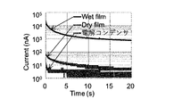
- FIG. 3 is a characteristic diagram showing measurement results of leakage currents of a dry film capacitor, a wet film capacitor, and an aluminum electrolytic capacitor.
- FIG. 4 is a characteristic diagram showing S 11 measurement results in the case of an LC circuit using a dry film capacitor, a wet film capacitor, and an aluminum electrolytic capacitor.
- FIG. 5 is an explanatory diagram for explaining a circuit used to perform a simulation for a configuration in which a communication circuit is an LC circuit and a sensor circuit is also an LC circuit.
- FIG. 6 is a characteristic diagram showing the results of a simulation of a configuration in which the communication circuit is an LC circuit and the sensor circuit is also an LC circuit.
- FIG. 7A is a characteristic diagram showing changes in resonance characteristics in a state in which a capacitor to which a "wet film” is applied in an LC+LC circuit is immersed in water.
- FIG. 7B is a characteristic diagram showing changes in resonance characteristics in a state in which a capacitor to which a "wet film” is applied in an LC+LC circuit is immersed in HCl/NaCl water simulating gastric juice.
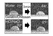
- FIG. 8 is a photograph showing the contact angle between water and the contact angle between HCl/NaCl water in the hydrogel film.
- FIGS. 1A, 1B, and 1C A resonant circuit according to an embodiment of the present invention will be described below with reference to FIGS. 1A, 1B, and 1C.
- This resonant circuit includes a sensor circuit 101 and a communication circuit 102 connected to the sensor circuit 101 .
- a sensor circuit 101 is composed of a first capacitor 103 and a first inductor 104 .
- Communication circuit 102 includes a second capacitor 105 and a second inductor 106 .
- a first inductor 104 is connected in series with the first capacitor 103 .
- a second capacitor 105 and a second inductor 106 are connected in parallel to the sensor circuit 101 .
- the first capacitor 103 includes two electrodes 111a and 111b, and a polymer film 112 made of sodium polyacrylate sandwiched between the electrodes 111a and 111b.
- the electrodes 111a and 111b can be films (metal films) made of metal such as Au.
- the electrodes can also be constructed from a conductive polymeric material.
- the first capacitor 103 also includes a biocompatible hydrogel film 113a and a hydrogel film 113b arranged to cover the outer surfaces of the electrodes 111a and 111b, respectively.
- the hydrogel film 113a and the hydrogel film 113b are composed of a first material that undergoes a sol-gel change at a temperature within a predetermined range centering on body temperature and is compatible with the body, and a second material that is compatible with the body and does not undergo a sol-gel change at temperature. Constructed from a mixture of materials.
- the first material can be gelatin and the second material can be chitosan.
- the first material can be a material having a melting point near body temperature, such as butter, cocoa butter, shea butter, coconut oil, or the like.
- the second material can also be a material with a slightly higher melting point, such as agar or agar.
- the first capacitor 103 is covered with a hydrogel film 113a and a hydrogel film 113b formed by mixing a first material that undergoes a sol-gel change near body temperature and a second material that does not undergo a sol-gel change. You can control your time.
- the hydrogel film 113a and the hydrogel film 113b swell and easily collapse by absorbing water in the body.
- the change in the internal environment can be measured from the collapse time of the first capacitor 103. If the first capacitor 103 collapses, the resonance frequency cannot be read outside the body via the communication circuit 102, so the time until collapse can be measured.
- the second capacitor 105 includes two electrodes 121a and 121b, and a polymer film 122 made of sodium polyacrylate sandwiched between the electrodes 121a and 121b. These configurations are similar to those of the first capacitor 103 .
- the second capacitor 105 includes a protective film 123a and a protective film 123b formed on the outer surfaces of the electrodes 121a and 121b to prevent water from penetrating into the electrodes 121a and 121b.
- the protective films 123a and 123b can be made of a waterproof material or a water-repellent material.
- the protective film 123a and the protective film 123b can be composed of, for example, an insolubilizing film composed of sodium alginate and calcium chloride.
- the protective films 123a and 123b can be made of a water-repellent film made of beeswax, for example.
- FIG. 2A and 2B show the impedance measurement results and capacitance of these capacitors.
- FIG. 2C shows the impedance of an aluminum electrolytic capacitor with a capacity of 100 nF.
- ESR equivalent series resistance consisting of losses in the dielectric and electrodes
- ESL parasitic inductance due to coil components of the electrodes and lead wires
- IR equivalent circuit due to resistance to leakage current flowing between the plates
- ESR equivalent series resistance
- C and ESL is determined by ESL.
- Fig. 3 shows the measurement results of the leakage current of each capacitor described above.
- the capacitance is higher, but the leakage current is also higher, as shown in FIG.
- FIG. 4 shows the S 11 measurement results for an LC circuit using a capacitor made of a biocompatible material.
- “Dry film” and electrolytic capacitors resonance can be confirmed according to the capacitance, but with “Wet film” resonance cannot be confirmed. This suggests that if water enters between the two electrodes (polymer film) that make up the capacitor, it may stop functioning.
- FIG. 5(b), (c), and (d) are equivalent circuits of a device in which a capacitor is connected to a tag formed with an LC circuit shown in FIG. 5(a) by a lead wire.
- FIG. 5(b) is an equivalent circuit of a tag forming an LC circuit
- FIG. 5(c) is an equivalent circuit of a lead wire
- FIG. 5(d) is an equivalent circuit of a capacitor.
- ESR corresponds to R3
- IR corresponds to R2.
- a simulation was performed using S 11 as the ratio to the power supply voltage at the position ⁇ in FIG. 5(b).
- the hydrogel film composed of gelatin and chitosan has different contact angles with water than with HCl/NaCl water.
- this hydrogel film has different absorption rates between water and HCl/NaCl water. Therefore, it is considered that the first capacitor 103 according to the embodiment also changes in the time during which it functions as a capacitor.
- the swelling time of the hydrogel membranes 113a and 113b can be controlled by changing the pore size after drying the hydrogel membranes 113a and 113b by changing the drying speed, temperature, and the like.
- a protective film such as a water-repellent film is formed on the outer surface of the hydrogel film 113a and the hydrogel film 113b to suppress the infiltration of water. Control such as extending the swelling time is possible.
- the target liquid is not limited to water
- the change in the swelling time of the gel can be controlled by using a gel whose volume change changes depending on the pH, ions, polymers, or other contents.
- the collapse time of the hydrogel film covering the electrodes of the first capacitor of the resonant circuit according to the embodiment the internal state of the body can be estimated based on the difference in time change in the S 11 measurement described above. can do.
- the sensor circuit is composed of the first capacitor and the first inductor, and the outer surface of each of the two electrodes of the first capacitor is covered with a hydrogel film, so a separate configuration is introduced. Therefore, it is possible to prevent the reduction of the reading distance and the difficulty of reading.
- the present invention by using an LC circuit in the sensor circuit, even if moisture enters between the plates of the first capacitor and leakage current occurs, the resonance frequency can be read via the communication circuit.
- the resonant circuit according to the present invention may be a wireless tag that measures the state of gastric juice or intestinal juice (pH, contents, etc.).
- the application is not limited to the inside of the body, and since biodegradable materials are used, measurement in water (external stimulation response gel is selected, for example, water quality survey, hydroponics, aquaculture, etc.) measurement of ions, pH, etc.).
Landscapes
- Chemical & Material Sciences (AREA)
- Chemical Kinetics & Catalysis (AREA)
- Electrochemistry (AREA)
- Physics & Mathematics (AREA)
- Health & Medical Sciences (AREA)
- Life Sciences & Earth Sciences (AREA)
- Analytical Chemistry (AREA)
- Biochemistry (AREA)
- General Health & Medical Sciences (AREA)
- General Physics & Mathematics (AREA)
- Immunology (AREA)
- Pathology (AREA)
- Investigating Or Analyzing Materials By The Use Of Electric Means (AREA)
Priority Applications (2)
| Application Number | Priority Date | Filing Date | Title |
|---|---|---|---|
| PCT/JP2021/014865 WO2022215220A1 (ja) | 2021-04-08 | 2021-04-08 | 共振回路 |
| JP2023512597A JP7537605B2 (ja) | 2021-04-08 | 2021-04-08 | 共振回路 |
Applications Claiming Priority (1)
| Application Number | Priority Date | Filing Date | Title |
|---|---|---|---|
| PCT/JP2021/014865 WO2022215220A1 (ja) | 2021-04-08 | 2021-04-08 | 共振回路 |
Publications (1)
| Publication Number | Publication Date |
|---|---|
| WO2022215220A1 true WO2022215220A1 (ja) | 2022-10-13 |
Family
ID=83545297
Family Applications (1)
| Application Number | Title | Priority Date | Filing Date |
|---|---|---|---|
| PCT/JP2021/014865 Ceased WO2022215220A1 (ja) | 2021-04-08 | 2021-04-08 | 共振回路 |
Country Status (2)
| Country | Link |
|---|---|
| JP (1) | JP7537605B2 (https=) |
| WO (1) | WO2022215220A1 (https=) |
Citations (10)
| Publication number | Priority date | Publication date | Assignee | Title |
|---|---|---|---|---|
| JP2009544009A (ja) * | 2006-07-10 | 2009-12-10 | スリーエム イノベイティブ プロパティズ カンパニー | 誘導センサ |
| JP2009544010A (ja) * | 2006-07-10 | 2009-12-10 | スリーエム イノベイティブ プロパティズ カンパニー | 可撓性誘導センサ |
| JP2010127927A (ja) * | 2008-12-01 | 2010-06-10 | Ind Technol Res Inst | 気体検知器 |
| JP2013509583A (ja) * | 2009-10-30 | 2013-03-14 | ゼネラル・エレクトリック・カンパニイ | 共振センサの性能向上のための方法及びシステム |
| JP2015114213A (ja) * | 2013-12-12 | 2015-06-22 | 国立大学法人山形大学 | 液体検知センサーおよび液体検知装置 |
| JP2016128803A (ja) * | 2014-12-30 | 2016-07-14 | ゼネラル・エレクトリック・カンパニイ | ガス状物質を検出するための材料及びセンサ |
| JP2017150888A (ja) * | 2016-02-23 | 2017-08-31 | 国立大学法人山形大学 | 液体検知センサおよび液体検知装置 |
| JP2017150889A (ja) * | 2016-02-23 | 2017-08-31 | 国立大学法人山形大学 | おむつ用液体検知センサおよび液体検知装置 |
| WO2019202157A1 (en) * | 2018-04-20 | 2019-10-24 | Pampett Ab | A method of manufacturing a device for detecting moisture at an absorbent article |
| US20200249237A1 (en) * | 2019-01-31 | 2020-08-06 | C2Sense, Inc. | Gas sensing identification |
-
2021
- 2021-04-08 WO PCT/JP2021/014865 patent/WO2022215220A1/ja not_active Ceased
- 2021-04-08 JP JP2023512597A patent/JP7537605B2/ja active Active
Patent Citations (10)
| Publication number | Priority date | Publication date | Assignee | Title |
|---|---|---|---|---|
| JP2009544009A (ja) * | 2006-07-10 | 2009-12-10 | スリーエム イノベイティブ プロパティズ カンパニー | 誘導センサ |
| JP2009544010A (ja) * | 2006-07-10 | 2009-12-10 | スリーエム イノベイティブ プロパティズ カンパニー | 可撓性誘導センサ |
| JP2010127927A (ja) * | 2008-12-01 | 2010-06-10 | Ind Technol Res Inst | 気体検知器 |
| JP2013509583A (ja) * | 2009-10-30 | 2013-03-14 | ゼネラル・エレクトリック・カンパニイ | 共振センサの性能向上のための方法及びシステム |
| JP2015114213A (ja) * | 2013-12-12 | 2015-06-22 | 国立大学法人山形大学 | 液体検知センサーおよび液体検知装置 |
| JP2016128803A (ja) * | 2014-12-30 | 2016-07-14 | ゼネラル・エレクトリック・カンパニイ | ガス状物質を検出するための材料及びセンサ |
| JP2017150888A (ja) * | 2016-02-23 | 2017-08-31 | 国立大学法人山形大学 | 液体検知センサおよび液体検知装置 |
| JP2017150889A (ja) * | 2016-02-23 | 2017-08-31 | 国立大学法人山形大学 | おむつ用液体検知センサおよび液体検知装置 |
| WO2019202157A1 (en) * | 2018-04-20 | 2019-10-24 | Pampett Ab | A method of manufacturing a device for detecting moisture at an absorbent article |
| US20200249237A1 (en) * | 2019-01-31 | 2020-08-06 | C2Sense, Inc. | Gas sensing identification |
Also Published As
| Publication number | Publication date |
|---|---|
| JP7537605B2 (ja) | 2024-08-21 |
| JPWO2022215220A1 (https=) | 2022-10-13 |
Similar Documents
| Publication | Publication Date | Title |
|---|---|---|
| CN105324652B (zh) | 压力感应植入物 | |
| US7248458B2 (en) | Orientation-insensitive ultra-wideband coupling capacitor and method of making | |
| JP7245792B2 (ja) | 安定した近距離アンテナを含む無線感知デバイス | |
| EP2041760A2 (en) | Inductive sensor | |
| US4264943A (en) | Hollow cored capacitor | |
| JP7537605B2 (ja) | 共振回路 | |
| JPH06120088A (ja) | チップ型固体電解コンデンサ | |
| US3518500A (en) | Flat plate feed-through capacitor | |
| US3236936A (en) | Miniature electrical component with protected terminal-wire connections | |
| KR100268529B1 (ko) | 리드단자를수지로도포한전자부품 | |
| CN101529540A (zh) | 螺旋电容器及其制造方法 | |
| CN111351596A (zh) | 一种测量温度的电容式传感器 | |
| CN107785170A (zh) | 固体电解电容器元件及其制造方法、固体电解电容器及其制造方法 | |
| US2552306A (en) | Artificial transmission line | |
| JP7537515B2 (ja) | キャパシタ | |
| US3371295A (en) | Distributed resistance-capacitance unit | |
| CN108054017A (zh) | 一种塑封无极性高分子聚合物钽电容器 | |
| CN219476502U (zh) | 耐潮防污电容器 | |
| JPS6096910A (ja) | ノイズ・フイルタ | |
| CN112515646A (zh) | 压力传感器及其制备方法和使用方法 | |
| US3258740A (en) | Hurley etal hydrophones | |
| CN210897611U (zh) | 一种方向图可重构的胶囊天线 | |
| JPH0342671Y2 (https=) | ||
| CN108022755A (zh) | 不需要负极导电箔片的电容器封装结构及其卷绕式组件 | |
| CN117233489A (zh) | 合成绝缘子串温度监测的无线传感装置及其制造方法 |
Legal Events
| Date | Code | Title | Description |
|---|---|---|---|
| 121 | Ep: the epo has been informed by wipo that ep was designated in this application |
Ref document number: 21936024 Country of ref document: EP Kind code of ref document: A1 |
|
| ENP | Entry into the national phase |
Ref document number: 2023512597 Country of ref document: JP Kind code of ref document: A |
|
| NENP | Non-entry into the national phase |
Ref country code: DE |
|
| 122 | Ep: pct application non-entry in european phase |
Ref document number: 21936024 Country of ref document: EP Kind code of ref document: A1 |