WO2022210986A1 - 表皮材 - Google Patents
表皮材 Download PDFInfo
- Publication number
- WO2022210986A1 WO2022210986A1 PCT/JP2022/016323 JP2022016323W WO2022210986A1 WO 2022210986 A1 WO2022210986 A1 WO 2022210986A1 JP 2022016323 W JP2022016323 W JP 2022016323W WO 2022210986 A1 WO2022210986 A1 WO 2022210986A1
- Authority
- WO
- WIPO (PCT)
- Prior art keywords
- layer
- skin material
- skin
- intermediate layer
- design
- Prior art date
- Legal status (The legal status is an assumption and is not a legal conclusion. Google has not performed a legal analysis and makes no representation as to the accuracy of the status listed.)
- Ceased
Links
Images



Classifications
-
- C—CHEMISTRY; METALLURGY
- C08—ORGANIC MACROMOLECULAR COMPOUNDS; THEIR PREPARATION OR CHEMICAL WORKING-UP; COMPOSITIONS BASED THEREON
- C08J—WORKING-UP; GENERAL PROCESSES OF COMPOUNDING; AFTER-TREATMENT NOT COVERED BY SUBCLASSES C08B, C08C, C08F, C08G or C08H
- C08J7/00—Chemical treatment or coating of shaped articles made of macromolecular substances
- C08J7/04—Coating
- C08J7/042—Coating with two or more layers, where at least one layer of a composition contains a polymer binder
-
- B—PERFORMING OPERATIONS; TRANSPORTING
- B23—MACHINE TOOLS; METAL-WORKING NOT OTHERWISE PROVIDED FOR
- B23K—SOLDERING OR UNSOLDERING; WELDING; CLADDING OR PLATING BY SOLDERING OR WELDING; CUTTING BY APPLYING HEAT LOCALLY, e.g. FLAME CUTTING; WORKING BY LASER BEAM
- B23K26/00—Working by laser beam, e.g. welding, cutting or boring
- B23K26/36—Removing material
- B23K26/362—Laser etching
- B23K26/364—Laser etching for making a groove or trench, e.g. for scribing a break initiation groove
-
- B—PERFORMING OPERATIONS; TRANSPORTING
- B23—MACHINE TOOLS; METAL-WORKING NOT OTHERWISE PROVIDED FOR
- B23K—SOLDERING OR UNSOLDERING; WELDING; CLADDING OR PLATING BY SOLDERING OR WELDING; CUTTING BY APPLYING HEAT LOCALLY, e.g. FLAME CUTTING; WORKING BY LASER BEAM
- B23K26/00—Working by laser beam, e.g. welding, cutting or boring
- B23K26/36—Removing material
- B23K26/40—Removing material taking account of the properties of the material involved
- B23K26/402—Removing material taking account of the properties of the material involved involving non-metallic material, e.g. isolators
-
- B—PERFORMING OPERATIONS; TRANSPORTING
- B32—LAYERED PRODUCTS
- B32B—LAYERED PRODUCTS, i.e. PRODUCTS BUILT-UP OF STRATA OF FLAT OR NON-FLAT, e.g. CELLULAR OR HONEYCOMB, FORM
- B32B3/00—Layered products comprising a layer with external or internal discontinuities or unevennesses, or a layer of non-planar shape; Layered products comprising a layer having particular features of form
- B32B3/26—Layered products comprising a layer with external or internal discontinuities or unevennesses, or a layer of non-planar shape; Layered products comprising a layer having particular features of form characterised by a particular shape of the outline of the cross-section of a continuous layer; characterised by a layer with cavities or internal voids ; characterised by an apertured layer
- B32B3/266—Layered products comprising a layer with external or internal discontinuities or unevennesses, or a layer of non-planar shape; Layered products comprising a layer having particular features of form characterised by a particular shape of the outline of the cross-section of a continuous layer; characterised by a layer with cavities or internal voids ; characterised by an apertured layer characterised by an apertured layer, the apertures going through the whole thickness of the layer, e.g. expanded metal, perforated layer, slit layer regular cells B32B3/12
-
- B—PERFORMING OPERATIONS; TRANSPORTING
- B32—LAYERED PRODUCTS
- B32B—LAYERED PRODUCTS, i.e. PRODUCTS BUILT-UP OF STRATA OF FLAT OR NON-FLAT, e.g. CELLULAR OR HONEYCOMB, FORM
- B32B3/00—Layered products comprising a layer with external or internal discontinuities or unevennesses, or a layer of non-planar shape; Layered products comprising a layer having particular features of form
- B32B3/26—Layered products comprising a layer with external or internal discontinuities or unevennesses, or a layer of non-planar shape; Layered products comprising a layer having particular features of form characterised by a particular shape of the outline of the cross-section of a continuous layer; characterised by a layer with cavities or internal voids ; characterised by an apertured layer
- B32B3/30—Layered products comprising a layer with external or internal discontinuities or unevennesses, or a layer of non-planar shape; Layered products comprising a layer having particular features of form characterised by a particular shape of the outline of the cross-section of a continuous layer; characterised by a layer with cavities or internal voids ; characterised by an apertured layer characterised by a layer formed with recesses or projections, e.g. hollows, grooves, protuberances, ribs
-
- B—PERFORMING OPERATIONS; TRANSPORTING
- B32—LAYERED PRODUCTS
- B32B—LAYERED PRODUCTS, i.e. PRODUCTS BUILT-UP OF STRATA OF FLAT OR NON-FLAT, e.g. CELLULAR OR HONEYCOMB, FORM
- B32B7/00—Layered products characterised by the relation between layers; Layered products characterised by the relative orientation of features between layers, or by the relative values of a measurable parameter between layers, i.e. products comprising layers having different physical, chemical or physicochemical properties; Layered products characterised by the interconnection of layers
- B32B7/02—Physical, chemical or physicochemical properties
- B32B7/023—Optical properties
-
- C—CHEMISTRY; METALLURGY
- C08—ORGANIC MACROMOLECULAR COMPOUNDS; THEIR PREPARATION OR CHEMICAL WORKING-UP; COMPOSITIONS BASED THEREON
- C08J—WORKING-UP; GENERAL PROCESSES OF COMPOUNDING; AFTER-TREATMENT NOT COVERED BY SUBCLASSES C08B, C08C, C08F, C08G or C08H
- C08J7/00—Chemical treatment or coating of shaped articles made of macromolecular substances
- C08J7/12—Chemical modification
- C08J7/123—Treatment by wave energy or particle radiation
-
- B—PERFORMING OPERATIONS; TRANSPORTING
- B23—MACHINE TOOLS; METAL-WORKING NOT OTHERWISE PROVIDED FOR
- B23K—SOLDERING OR UNSOLDERING; WELDING; CLADDING OR PLATING BY SOLDERING OR WELDING; CUTTING BY APPLYING HEAT LOCALLY, e.g. FLAME CUTTING; WORKING BY LASER BEAM
- B23K2101/00—Articles made by soldering, welding or cutting
- B23K2101/006—Vehicles
-
- B—PERFORMING OPERATIONS; TRANSPORTING
- B23—MACHINE TOOLS; METAL-WORKING NOT OTHERWISE PROVIDED FOR
- B23K—SOLDERING OR UNSOLDERING; WELDING; CLADDING OR PLATING BY SOLDERING OR WELDING; CUTTING BY APPLYING HEAT LOCALLY, e.g. FLAME CUTTING; WORKING BY LASER BEAM
- B23K2103/00—Materials to be soldered, welded or cut
- B23K2103/16—Composite materials
- B23K2103/166—Multilayered materials
- B23K2103/172—Multilayered materials wherein at least one of the layers is non-metallic
-
- B—PERFORMING OPERATIONS; TRANSPORTING
- B23—MACHINE TOOLS; METAL-WORKING NOT OTHERWISE PROVIDED FOR
- B23K—SOLDERING OR UNSOLDERING; WELDING; CLADDING OR PLATING BY SOLDERING OR WELDING; CUTTING BY APPLYING HEAT LOCALLY, e.g. FLAME CUTTING; WORKING BY LASER BEAM
- B23K2103/00—Materials to be soldered, welded or cut
- B23K2103/30—Organic materials
- B23K2103/32—Material from living organisms, e.g. skins
- B23K2103/34—Leather
-
- B—PERFORMING OPERATIONS; TRANSPORTING
- B32—LAYERED PRODUCTS
- B32B—LAYERED PRODUCTS, i.e. PRODUCTS BUILT-UP OF STRATA OF FLAT OR NON-FLAT, e.g. CELLULAR OR HONEYCOMB, FORM
- B32B2605/00—Vehicles
- B32B2605/003—Interior finishings
-
- B—PERFORMING OPERATIONS; TRANSPORTING
- B60—VEHICLES IN GENERAL
- B60R—VEHICLES, VEHICLE FITTINGS, OR VEHICLE PARTS, NOT OTHERWISE PROVIDED FOR
- B60R7/00—Stowing or holding appliances inside vehicle primarily intended for personal property smaller than suit-cases, e.g. travelling articles, or maps
- B60R7/04—Stowing or holding appliances inside vehicle primarily intended for personal property smaller than suit-cases, e.g. travelling articles, or maps in driver or passenger space, e.g. using racks
-
- C—CHEMISTRY; METALLURGY
- C08—ORGANIC MACROMOLECULAR COMPOUNDS; THEIR PREPARATION OR CHEMICAL WORKING-UP; COMPOSITIONS BASED THEREON
- C08J—WORKING-UP; GENERAL PROCESSES OF COMPOUNDING; AFTER-TREATMENT NOT COVERED BY SUBCLASSES C08B, C08C, C08F, C08G or C08H
- C08J2300/00—Characterised by the use of unspecified polymers
- C08J2300/12—Polymers characterised by physical features, e.g. anisotropy, viscosity or electrical conductivity
Definitions
- the present invention relates to a skin material used for interior parts of a vehicle, for example.
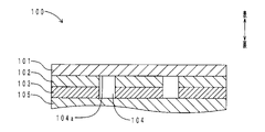
- FIG. 11 shows a cross-sectional view of the decorative sheet of Patent Document 1 in the front and back directions.
- the skin material (decorative sheet) 100 includes a base material portion 101, a pattern portion 102, and a shielding portion 103 from the front side to the back side.
- the skin material 100 also has a plurality of recesses (light transmitting portions) 104 .
- a plurality of recesses 104 are arranged in portions where the pattern portion 102 and the shielding portion 103 are removed.
- the recessed portion 104 has a recessed shape that opens to the back surface of the upholstery material 100 .
- a display device 105 is arranged on the back side of the skin material 100 .
- the display device 105 When the display device 105 is off, the design of the skin material 100 itself appears on the surface of the skin material 100 . When the display device 105 is on, predetermined patterns, switches, and the like appear on the surface of the skin material 100 due to the light transmitted through the plurality of concave portions 104 and the base material portion 101 .
- the bottom surface 104a of all the concave portions 104 is uniformly used on the back surface of the base material portion 101. Therefore, the light that has passed through all the concave portions 104 uniformly passes through the base material portion 101 and appears on the surface of the skin material 100 . Therefore, the degree of design freedom is low. Further, according to the skin material 100 of Patent Document 1, the depth of the bottoms 104a of all the recesses 104 (the depth from the back surface of the skin material 100) is constant. Also in this respect, the degree of design freedom is low. Further, according to the skin material 100 of Patent Document 1, all the concave portions 104 uniformly extend in the surface normal direction of the surface of the decorative sheet 100 . Also in this respect, the degree of design freedom is low. Accordingly, an object of the present invention is to provide a skin material with a high degree of design freedom.
- the skin material of the present invention comprises a skin layer having translucency, an intermediate layer disposed on the back side of the skin layer and having a lower translucency than the skin layer, and the intermediate layer a design layer arranged on the back side of the intermediate layer and having a lower translucency than the intermediate layer; It is characterized by having an intermediate layer reaching portion arranged in the intermediate layer.
- the mode in which the bottom of the recess has the intermediate layer reaching portion includes the mode in which part of the bottom of a single recess is the intermediate layer reaching portion, and the mode in which some of the bottoms of a plurality of recesses have intermediate layer reaching portions.
- a form that is a layer reaching part, etc. are included.
- the skin material of the present invention comprises a skin layer having translucency, an intermediate layer disposed on the back side of the skin layer and having a lower translucency than the skin layer, and the A skin material comprising a design layer disposed on the back side of an intermediate layer and having a lower translucency than the intermediate layer, and at least one recess opening in the back surface of the design layer, wherein the bottom of the recess is , a base portion, and a deep bottom portion deeper than the base portion.
- the form in which the bottom of the recess has a base part and a deep part includes a form in which part of the bottom of a single recess is the base part and the rest is the deep part. Forms in which some bottoms are basal and remaining bottoms are deep are included.
- the skin material of the present invention comprises a skin layer having translucency, an intermediate layer disposed on the back side of the skin layer and having a lower translucency than the skin layer, and the A skin material comprising a design layer disposed on the back side of an intermediate layer and having a lower translucency than the intermediate layer, and at least one recess opening in the back surface of the design layer, wherein the side surface of the recess is and an inclined portion extending in a direction intersecting with a surface normal direction of the surface of the skin layer.
- the form in which the side surface of the recess has an inclined portion includes a form in which a part of the side surface of a single recess is an inclined part, a form in which a part of the side surfaces of a plurality of recesses is an inclined part, and the like. is included.
- the bottom of the concave portion of the skin material of the present invention has an intermediate layer reaching portion.
- the intermediate layer reach is arranged within the layer of the intermediate layer. Therefore, the light transmittance can be reduced as compared with the case where the bottoms of the recesses are uniformly the back surface of the skin layer. On the contrary, the light transmittance can be improved compared to the case where the bottom of the recess is uniformly the back surface of the intermediate layer. Further, when the intermediate layer reaching portion is arranged closer to the skin layer, the concave portion becomes deeper accordingly. Therefore, the light transmittance can be improved. On the contrary, if the intermediate layer reaching portion is arranged closer to the design layer, the concave portion becomes shallower accordingly. Therefore, the light transmittance can be reduced. In this way, by adjusting the front-back direction position of the intermediate layer reaching portion, it is possible to adjust the design that appears on the surface of the upholstery material. Therefore, the degree of design freedom is increased.
- the bottom of the concave portion of the skin material of the present invention has a base portion and a deep bottom portion.
- the depth of the concave portion differs between the base portion and the deep bottom portion. Due to the depth difference, a difference in light transmittance can be provided. Therefore, the design that appears on the surface of the skin material can be adjusted. Therefore, the degree of design freedom is increased.
- the side surface of the concave portion of the skin material of the present invention has an inclined portion.
- the inclined portion extends in a direction intersecting the surface normal direction of the surface of the skin layer. Therefore, when light traveling through the concave portion in the normal direction of the surface is incident on the inclined portion, at least part of the light may be reflected by the inclined portion. Also, light may be refracted by the inclined portion. Therefore, the design that appears on the surface of the skin material can be adjusted. Therefore, the degree of design freedom is increased.
- FIG. 1 is a layout diagram of the skin material of the first embodiment.
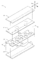
- 2 is an exploded perspective view within a frame II of FIG. 1.
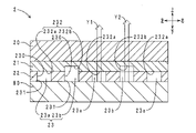
- FIG. 3 is a cross-sectional view taken along the line III-III of FIG.
- FIG. 4 is a schematic diagram of a laser processing step in the manufacturing method of the skin material.
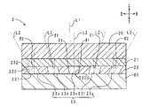
- FIG. 5 is a front-rear cross-sectional view of the skin material of the second embodiment.
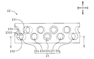
- 6 is a surface view of the design layer of FIG. 5.
- FIG. FIG. 7 is a front-rear cross-sectional view of the skin material of the third embodiment.
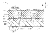
- FIG. 8 is a front-rear cross-sectional view of the skin material of the fourth embodiment.
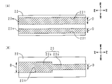
- FIG. 9A is a back view of the design layer of the skin material of another embodiment (No. 1).
- FIG. 9(B) is a back view of the design layer of the skin material of another embodiment (No. 2).
- FIG. 10 is a cross-sectional view in the front and back direction of the skin material of another embodiment (No. 3).
- FIG. 11 is a cross-sectional view of a conventional decorative sheet in the front and back direction.
- FIG. 1 shows a layout diagram of the skin material of this embodiment.
- FIG. 2 shows an exploded perspective view within frame II of FIG.
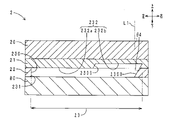
- FIG. 3 shows a cross-sectional view along the III-III direction of FIG.
- FIG. 4 shows a schematic diagram of a laser processing step in the manufacturing method of the skin material. 3 and 4, the thickness in the front-back direction is emphasized.
- the skin material 2 is arranged on the entire surface (upper surface) of the console box (interior part) 90 of the passenger compartment.
- the skin material 2 includes a skin layer 20, an intermediate layer 21, a design layer 22, and a plurality of concave portions from the front side (inside the vehicle, upper side) to the back side (outer side, lower side). 23 and.
- the skin layer 20 is made of synthetic leather and has a layered shape.
- the skin layer 20 has translucency and flexibility.
- a textured pattern (not shown) is formed on the surface of the skin layer 20 .
- the intermediate layer 21 is laminated on the back surface (lower surface) of the skin layer 20 .
- the intermediate layer 21 is made of translucent ink and has a layered shape.
- the intermediate layer 21 has translucency and flexibility.
- the intermediate layer 21 has lower translucency than the skin layer 20 . That is, the intermediate layer 21 is smoky translucent. Further, the intermediate layer 21 is colored and transparent.
- the design layer 22 is laminated on the back surface of the intermediate layer 21 .
- the design layer 22 is made of opaque ink and has a layered shape.
- the design layer 22 has opacity and flexibility. That is, the design layer 22 does not transmit light.
- a plurality of recesses 23 are recessed in the back surface of the design layer 22 . Concave portion 23 will be described later in detail.
- a sheet-like light source 80 is arranged on the back side of the design layer 22 , that is, the back side of the skin material 2 .
- the light source 80 includes a plurality of LEDs (not shown). The surface of the light source 80 can emit light entirely.
- the plurality of recesses 23 are arranged over the entire back surface of the design layer 22, and as a whole form a polka dot design as shown in FIG.
- the concave portion 23 has a circular shape when viewed from the front and back directions.
- the internal space of the recess 23 has a cylindrical shape.
- the plurality of recesses 23 are classified into a plurality of reference recesses 23a and a plurality of deep recesses 23b.
- the reference recesses 23 a and the deep recesses 23 b are alternately arranged in the left-right direction (uniaxial direction) on the lower surface of the design layer 22 .
- the reference concave portion 23a includes a side surface (inner peripheral surface) 230, an opening portion 231, and a base portion 232a.
- the side surface 230 extends in the front-back direction.
- the side surface 230 has the shape of a straight pipe (specifically, the shape of the inner peripheral surface of a straight pipe).
- the side surface 230 extends parallel to the surface normal direction of the surface of the skin layer 20 .
- the opening 231 is arranged on the back surface of the design layer 22 .
- the base portion 232 a is arranged on the front side of the opening portion 231 .
- the deep recess 23b has a side surface (inner peripheral surface) 230 and an opening 231, like the reference recess 23a.
- the deep recess 23b has a deep bottom 232b instead of the base 232a.
- the deep bottom portion 232b is included in the concepts of "deep bottom portion" and "intermediate layer reaching portion” of the present invention.
- the only difference between the reference concave portion 23a and the deep concave portion 23b is the bottom portion 232 (base portion 232a, deep bottom portion 232b). Both the reference recess 23 a and the deep recess 23 b penetrate the design layer 22 . The reference recess 23 a does not reach the intermediate layer 21 . The base portion 232 a is arranged on the lower surface of the intermediate layer 21 . On the other hand, the deep recess 23b reaches the intermediate layer 21 . The deep bottom portion 232b is arranged in the middle of the intermediate layer 21 in the front-back direction.
- the manufacturing method of the skin material of this embodiment has a lamination process and a laser processing process.
- the lamination step the intermediate layer 21 and the design layer 22 are laminated on the back surface of the skin layer 20 by screen printing.
- the laminate is placed inside out (so that the back surface of the design layer 22 faces upward)
- a laser processing machine 91 is used to form recesses 23 (reference recesses 23 a and deep recesses 23 b ) on the back surface of the design layer 22 .
- a nozzle 910 of the laser processing machine 91 is relatively movable in the horizontal direction Y3 and the swing direction Y4 with respect to the laminate.
- a polka dot design consisting of a plurality of concave portions 23 is formed on the back surface of the design layer 22 .
- the depth of the recess 23 is adjusted by adjusting the laser output (power value). That is, the reference concave portion 23a and the deep concave portion 23b are separately formed.
- the skin material 2 is arranged on the front side of the light source 80 .
- the light source 80 When the light source 80 is on, the light source 80 emits light. For this reason, on the surface of the skin material 2, light transmitted through the plurality of reference recesses 23a, the intermediate layer 21 (the entire length of the thickness in the front-back direction), and the skin layer 20 (see arrow Y1 in FIG. 3), and a plurality of depths Light transmitted through the recesses 23b, the intermediate layer 21 (part of the thickness in the front-back direction), and the skin layer 20 (see arrow Y2 in FIG. 3) appears.
- the design of the design layer 22 (the polka dot pattern shown in FIG. 2) appears on the surface of the skin material 2 by these two types of light.
- the light transmitted through the deep recess 23b (arrow Y2) is brighter than the light transmitted through the reference recess 23a (arrow Y1). Therefore, on the surface of the skin material 2, two types of light and dark polka dot patterns emerge.
- the skin material 2 has a deep recess 23b, that is, a deep bottom 232b.
- the deep bottom 232b is arranged within the intermediate layer 21 layer. Therefore, the light transmittance can be reduced compared to the case where the bottoms 232 of the recesses 23 are uniformly the back surface of the skin layer 20 . On the contrary, the transmittance of light from the light source 80 can be improved compared to the case where the bottom 232 of the recess 23 is uniformly the back surface of the intermediate layer 21 . Further, when the deep bottom portion 232b is arranged closer to the skin layer 20, the deep recess portion 23b becomes deeper accordingly.
- the transmittance of light from the light source 80 can be improved.
- the deep bottom portion 232b is arranged closer to the design layer 22, the deep concave portion 23b becomes shallower accordingly. Therefore, the transmittance of light from the light source 80 can be reduced.
- the position of the deep bottom portion 232b in the front-back direction in this way, the design that appears on the surface of the upholstery material 2 can be adjusted. Therefore, the degree of design freedom is increased.
- the depth of the recess 23 differs between the base portion 232a and the deep bottom portion 232b. Due to the depth difference, a difference in light transmittance can be provided. Therefore, the design that appears on the surface of the skin material 2 can be adjusted. Therefore, the degree of design freedom is increased.
- the skin material 2 is provided with a translucent intermediate layer 21 . Therefore, when the light source 80 is off, the design of the design layer 22 can be suppressed from appearing on the surface of the skin material 2 . On the other hand, when the light source 80 is on, it can help the design of the design layer 22 to appear on the surface of the skin material 2 .
- the method for manufacturing the skin material 2 of the present embodiment has a lamination step and a laser processing step. According to the method for manufacturing the skin material 2 of the present embodiment, after the design layer 22 is printed on the back surface of the intermediate layer 21, the recesses 23 can be arranged in the design layer 22 by laser processing. Therefore, even if the design of the design layer 22 is changed, it is not necessary to change the screen mask one by one.
- the design of the design layer 22 can be changed simply by changing the movement of the nozzle 910 shown in FIG. 4 and the laser output. Therefore, the cost and downtime required for design change can be reduced. In addition, it is suitable for manufacturing a large variety of skin materials 2 in small quantities.
- ⁇ Second embodiment> A difference between the skin material of this embodiment and the skin material of the first embodiment is that the concave portion has an inclined portion. Only the points of difference are described here.
- FIG. 5 shows a front-back cross-sectional view of the skin material of this embodiment. Parts corresponding to those in FIG. 3 are denoted by the same reference numerals.
- the five recesses 23 are classified into one vertical recess 23c and four inclined recesses 23d to 23g.
- the bottoms 232 of the five recesses 23 (the vertical recesses 23c and the inclined recesses 23d to 23g) are arranged on the back surface of the intermediate layer 21, respectively.
- a side surface 230 of the recess 23 has an inclined portion 2300 .
- the vertical concave portion 23c extends in the vertical direction (front and back direction). That is, the axis L2 of the vertical concave portion 23c extends parallel to the direction in which the surface normal L1 of the surface of the skin layer 20 extends (front and back direction) (the inclination angle is 0°).
- An inclined portion 2300 of the vertical concave portion 23c has a tapered shape that tapers from the front side toward the back side at an inclination angle ⁇ 1.
- the inclined recess 23d to the left of the vertical recess 23c extends leftward from the opening 231 toward the bottom 232 (from the back side to the front side). That is, the axis L2 of the inclined recess 23d is inclined leftward by the inclination angle ⁇ 1 with respect to the extending direction of the surface normal L1.
- a side surface 230 of the inclined recess 23d has a straight tubular shape. Therefore, the inclined portion 2300 is inclined leftward by the inclination angle ⁇ 1, like the axis L2.
- the inclined recessed portion 23e on the left side of the inclined recessed portion 23d extends leftward from the opening portion 231 toward the bottom portion 232. That is, the axis L2 of the inclined recess 23e is inclined leftward with respect to the extending direction of the surface normal L1 by an inclination angle ⁇ 2 (> ⁇ 1).
- a side surface 230 of the inclined recess 23e has a straight tubular shape. Therefore, the inclined portion 2300 is inclined leftward by an inclination angle ⁇ 2, like the axis L2.
- the inclined recessed portion 23f on the right side of the vertical recessed portion 23c extends rightward from the opening portion 231 toward the bottom portion 232 at an inclination angle ⁇ 1.
- Other configurations are the same as those of the inclined recess 23d.
- the inclined recessed portion 23g on the right side of the inclined recessed portion 23f extends rightward from the opening portion 231 toward the bottom portion 232 at an inclination angle ⁇ 2.
- Other configurations are the same as those of the inclined recess 23e.
- Fig. 6 shows a surface view of the design layer in Fig. 5.
- the design layer in FIG. 5 corresponds to the cross-sectional view taken along the line VV in FIG.
- the outer peripheral edges of the bottoms 232 of the five recesses 23 (the vertical recesses 23c and the inclined recesses 23d to 23g) and the outer peripheral edges of the openings 231 do not match. That is, when seen through from the front side, the outer peripheral edges of the bottoms 232 of the five recesses 23 and the outer peripheral edges of the openings 231 are arranged so as to be offset from each other.
- the skin material of the present embodiment and the skin material of the first embodiment have the same action and effect with respect to the portions having the common configurations.
- side surfaces 230 of a plurality of recesses 23 each have an inclined portion 2300.
- the inclined portion 2300 extends in a direction crossing the extending direction of the surface normal L1. Therefore, when the light traveling in the direction of the surface normal L ⁇ b>1 in the concave portion 23 is incident on the inclined portion 2300 , at least part of the light may be reflected by the inclined portion 2300 . Also, the light may be refracted by the inclined portion 2300 . Therefore, the design that appears on the surface of the skin material 2 can be adjusted. Therefore, the degree of design freedom is increased.
- the inclination directions of the plurality of concave portions 23 are different from each other. In this respect as well, the design that appears on the surface of the skin material 2 can be adjusted. In addition, a plurality of inclination angles (0°, ⁇ 1, ⁇ 2) are set for the inclined portions 2300 of the plurality of concave portions 23 . In this respect as well, the design that appears on the surface of the skin material 2 can be adjusted.
- ⁇ Third embodiment> The difference between the skin material of this embodiment and the skin materials of the first and second embodiments is that the concave portion has an intermediate layer reaching portion, a base portion, a deep bottom portion, and an inclined portion. Another difference is that the intermediate layer has a two-layer structure. Only the points of difference are described here.
- FIG. 7 shows a front-back cross-sectional view of the skin material of this embodiment. Parts corresponding to those in FIGS. 3 and 5 are denoted by the same reference numerals.
- the intermediate layer 21 includes a surface layer (first layer) 210 and a back layer (second layer) 211 . Each of the surface layer 210 and the back layer 211 has translucency.
- the back layer 211 has a lower translucency than the surface layer 210 . Also, the back layer 211 and the surface layer 210 have different colors.
- the recess 23l on the right end corresponds to the reference recess 23a in FIG.
- the remaining four recesses 23h-23k correspond to the deep recess 23b in FIG. That is, the bottom portion (specifically, the front side edge of the bottom portion; the same applies hereinafter) 232l of the concave portion 23l is included in the concept of the "base portion" of the present invention. Further, the bottoms 232h-232k of the recesses 23h-23k are included in the concepts of "deep bottom” and "intermediate layer reaching portion” of the present invention. The bottoms 232 h - 232 k are arranged within layers of the intermediate layer 21 .
- the five recesses 23h to 23l correspond to the inclined recesses 23d to 23g in FIG. That is, the side surfaces 230 of the five recesses 23h to 23l each have an inclined portion 2300. As shown in FIG. The axes L2 of the five concave portions 23h to 23l are inclined rightward by an inclination angle ⁇ 3 with respect to the extending direction of the surface normal L1. Side surfaces 230 of the five recesses 23h to 23l each have a straight tubular shape. Therefore, the five inclined portions 2300 are inclined rightward by the inclination angle ⁇ 3, like the axis L2.
- a plurality of inclined portions 2300 may be inclined in the same direction as in this embodiment. In this way, the design appearing on the surface of the upholstery material 2 can have directivity (the characteristic that the design is easily visible from a predetermined direction (for example, the driver's seat side and the passenger's seat side)). Also, the plurality of inclined portions 2300 may be inclined at the same inclination angle ⁇ 3. In this way, the degrees of reflection and refraction of light can be made uniform in the plurality of inclined portions 2300 . Therefore, the design appearing on the surface of the skin material 2 can be made uniform.
- the depths of the plurality of recesses 23h to 23l may all be different.
- the base portion 232l of the concave portion 23l may be arranged within the design layer 22 .
- the intermediate layer 21 may be composed of a plurality of layers (the surface layer 210 and the back layer 211).
- the intermediate layer 21 may be composed of a plurality of layers, and the translucency of each layer may be gradually decreased from the front side to the back side.
- the intermediate layer 21 may be composed of a plurality of layers, and each layer may have a different color.
- the design layer 22 when the design layer 22 has translucency, the design layer 22 may be composed of a plurality of layers, and the translucency of each layer may be gradually reduced from the front side to the back side. Moreover, the design layer 22 may be composed of a plurality of layers, and each layer may have a different color.
- ⁇ Fourth embodiment> The difference between the skin material of this embodiment and the skin material of the third embodiment is that a single concave portion has an intermediate layer reaching portion, a base portion, a deep bottom portion, and an inclined portion. Another difference is that the intermediate layer has a single-layer structure. Only the points of difference are described here.
- FIG. 8 shows a front-back cross-sectional view of the skin material of this embodiment. Parts corresponding to those in FIGS. 3 and 5 are denoted by the same reference numerals.
- the bottom portion 232 of the recess 23 has a base portion 232a and a deep bottom portion 232b.
- the deep bottom portion 232b is included in the concepts of "deep bottom portion” and "intermediate layer reaching portion” of the present invention.
- An inclined portion 2300 is arranged in a portion of the side surface 230 of the recess 23 that continues to the deep bottom portion 232b.
- the inclined portion 2300 is inclined rightward by an inclination angle ⁇ 4 with respect to the extending direction of the surface normal L1.
- a single concave portion 23 may include a base portion 232a, a deep bottom portion (intermediate layer reaching portion) 232b, and an inclined portion 2300 as in this embodiment.
- FIG. 9A shows a back view of the design layer of the skin material of another embodiment (No. 1).
- FIG. 9B shows a back view of the design layer of the skin material of another embodiment (No. 2). Parts corresponding to those in FIG. 3 are denoted by the same reference numerals. Moreover, hatching is applied to the concave portion.
- each of the two recesses 23m and 23n has a strip shape extending in the left-right direction.
- 23 m of recessed parts are included in the concept of the "wide part" of this invention.
- the concave portion 23n is included in the concept of the "basal width portion” of the present invention.
- the recess 23m has an opening width (specifically, the width in the front-rear direction of the opening 231 (the width in the direction orthogonal to the extending direction of the recesses 23m and 23n; the width in the lateral direction)) D that is wider than the recess 23n.
- the concave portion 23 has a strip shape extending in the left-right direction.
- the left portion 23o of the recess 23 is included in the concept of the "wide portion” of the present invention.
- the right portion 23p is included in the concept of the "basal portion” of the present invention.
- the left portion 23o has a wider opening width D than the right portion 23p.
- FIGS. 9A and 9B by arranging portions (base width portion and wide width portion) having different opening widths D in the recess 23, the design that appears on the surface of the upholstery material 2 can be adjusted. be able to. Therefore, the degree of design freedom is increased. 9(A) and 9(B) can be incorporated into the recesses 23 shown in FIGS. 3, 5, 7 and 8. FIG.
- FIG. 10 shows a cross-sectional view of the surface material of another embodiment (No. 3) in the front and back direction. Parts corresponding to those in FIG. 3 are denoted by the same reference numerals.
- the intermediate layer 21 includes a left layer (first layer) 212 and a right layer (second layer) 213 . Each of the left layer 212 and the right layer 213 has translucency. The left layer 212 and the right layer 213 are different in color and translucency.
- the design layer 22 includes a left layer (first layer) 222 and a right layer (second layer) 223 . Each of the left layer 222 and the right layer 223 is opaque. The left layer 222 and the right layer 223 have different colors. As shown in FIG.
- At least one of the intermediate layer 21 and the design layer 22 may have a plurality of layers arranged in the surface direction (direction orthogonal to the front-back direction). By doing so, the design that appears on the surface of the skin material 2 can be adjusted. Therefore, the degree of design freedom is increased.
- the positions of the base portions 232a, 232l and the deep bottom portions 232b, 232h to 232k shown in FIGS. 3, 7 and 8 are not particularly limited. It may be inside the design layer 22 (when the design layer 22 is translucent), on the back surface of the intermediate layer 21, inside the intermediate layer 21, or the like.
- the inclination angle and extending direction (inclination direction) of the inclined portion 2300 shown in FIGS. 5, 7, and 8 are not particularly limited.
- the design that appears on the skin material 2 by the recesses 23 is not particularly limited. For example, patterns (polka dots, striped patterns, lattice patterns, heathered patterns, marble patterns, etc.), characters (alphabet, hiragana, katakana, kanji, numbers, etc.), figures (polygons, circles, etc.), symbols (for device operation) buttons, icons indicating device status, etc.).
- the color of the design appearing on the skin material 2 may be monochromatic or multicolored. The color may be displayed on the skin material 2 by one or more selected from the skin layer 20 , the intermediate layer 21 , the design layer 22 and the light source 80 . In particular, if a portion overlapping with the concave portion 23 when viewed from the front side is colored, the light from the light source 80 tends to cause the skin material 2 to develop a color.
- the translucency of the skin layer 20 and intermediate layer 21 is not particularly limited. It may be colorless and transparent, colored and transparent, translucent, and the like.
- the intermediate layer 21 may have a gradation in which the color changes from the back surface to the front surface. In this way, the color that appears on the surface of the upholstery material 2 can be changed according to the positions of the intermediate layer reaching portions (the deep bottom portion 232b in FIGS. 3 and 8 and the bottom portions 232h to 232k in FIG. 7).
- the gradation of the intermediate layer 21 may be formed by a plurality of layers.
- the design layer 22 does not have to be opaque. In other words, the design layer 22 should have a lower translucency than the intermediate layer 21 .
- the design layer 22 may have a gradation in which the color changes from the back surface to the front surface. By doing so, the color that appears on the surface of the upholstery material 2 can be changed according to the position of the bottom portion (the base portion 232l in FIG. 7).
- the colors (hue, saturation, brightness) of the skin layer 20, the intermediate layer 21, the design layer 22, and the light source 80 are not particularly limited. Also, the brightness of the light source 80 is not particularly limited.
- a translucent sensor for example, a capacitive sensor
- the skin material 2 can be used as a sensor or a switch.
- the timing at which the light source 80 is turned on is not particularly limited. It may be always on. Also, the light source 80 may be turned on in conjunction with the room lamp, headlight, or the like of the vehicle. Alternatively, the light source 80 may be turned on when a proximity sensor (for example, a capacitive sensor) detects the proximity of the user to the upholstery 2 .
- a proximity sensor for example, a capacitive sensor
- the type of light source 80 is not particularly limited. It may be an organic EL sheet or an inorganic EL sheet. Also, the light source 80 may include a light source main body (for example, an LED) and a light guide plate (for example, an acrylic plate). In this case, the light source body may be arranged next to the light guide plate in the surface direction, the surface of the light guide plate may be surface-emitting, and the skin material 2 may be arranged on the front side of the light guide plate.
- the light source 80 may be a phosphorescent sheet.
- the interior parts on which the skin material 2 is arranged are not particularly limited. Examples include door trims, seats, floors, ceilings, instrument panels, center clusters, glove compartments, steering wheels (handles), center consoles, and registers.
- the surface on which the skin material 2 is installed in the interior member may be flat or curved.
- the orientation (orientation in the front/back direction) when arranging the skin material 2 is not particularly limited.
- the skin material 2 may be arranged on interior parts of ships, aircraft, buildings, and houses other than vehicles.
- the configuration of the skin material 2 is not particularly limited. Of the skin layer 20, the intermediate layer 21, the design layer 22, and the light source 80, two layers adjacent in the front and back direction (between the skin layer 20 and the intermediate layer 21, between the intermediate layer 21 and the design layer 22, and the design layer 22) and the light source 80), other layers may be interposed. Further, another layer may be arranged on the front side of the skin layer 20 .
- the material of the skin layer 20 is not particularly limited. Examples include synthetic leather, resins, elastomers, nonwoven fabrics, and various types of cloth (woven fabrics, knitted fabrics, etc.). Synthetic leather, resins, and elastomers include acrylic, polyethylene terephthalate, polycarbonate, polyvinyl chloride, silicone, epoxy, polyurethane, styrenic thermoplastic elastomers, olefinic thermoplastic elastomers, dynamic cross-linking thermoplastic elastomers, and the like. is mentioned. Examples of nonwoven fabrics and various fabrics include polyester, polypropylene, nylon, and cotton.
- the skin layer 20 may contain colored particles such as colored polyethylene particles, light diffusing particles such as titanium oxide, and light absorbing particles such as titanium black and carbon black.
- the visible light transmittance of the skin layer 20 is preferably 50% or more and 100% or less. This makes it possible to make the design of the design layer 22 stand out more on the surface of the skin material 2 when the light source 80 is turned on.
- the visible light transmittance is a value calculated by measuring the transmission spectrum at a wavelength of 380 to 780 nm with a spectrophotometer "UV3100PC" manufactured by Shimadzu Corporation in accordance with JIS A5759:2016. adopt.
- the material of the intermediate layer 21 is not particularly limited. Examples include resins and elastomers such as acrylic, polyethylene terephthalate, polycarbonate, polyvinyl chloride, silicone, polyester, epoxy, polyurethane, styrene-based thermoplastic elastomer, olefin-based thermoplastic elastomer, and dynamic cross-linking thermoplastic elastomer. .
- the intermediate layer 21 may contain colored particles such as colored polyethylene particles, light diffusing particles such as titanium oxide, and light absorbing particles such as titanium black and carbon black.
- the visible light transmittance of the intermediate layer 21 is preferably more than 0% and 40% or less. This makes the design of the design layer 22 less noticeable when the light source 80 is off.
- the material of the design layer 22 is not particularly limited. Examples include resins and elastomers such as acrylic, polyethylene terephthalate, polycarbonate, polyvinyl chloride, silicone, polyester, epoxy, polyurethane, styrene-based thermoplastic elastomer, olefin-based thermoplastic elastomer, and dynamic cross-linking thermoplastic elastomer. .
- the design layer 22 may contain colored particles such as colored polyethylene particles, light diffusing particles such as titanium oxide, and light absorbing particles such as titanium black and carbon black.
- the method of laminating the skin layer 20, the intermediate layer 21, and the design layer 22 is not particularly limited. In addition to screen printing, gravure printing, inkjet printing, flexographic printing, and the like may be used. Moreover, each layer may be laminated by adhesion, vapor deposition, or the like. A method for forming the concave portion 23 is not particularly limited. In addition to laser processing, photoetching or the like may be used.
Landscapes
- Chemical & Material Sciences (AREA)
- Engineering & Computer Science (AREA)
- Physics & Mathematics (AREA)
- Optics & Photonics (AREA)
- Medicinal Chemistry (AREA)
- Organic Chemistry (AREA)
- Polymers & Plastics (AREA)
- Health & Medical Sciences (AREA)
- Chemical Kinetics & Catalysis (AREA)
- Plasma & Fusion (AREA)
- Mechanical Engineering (AREA)
- General Chemical & Material Sciences (AREA)
- Laminated Bodies (AREA)
- Laser Beam Processing (AREA)
Abstract
表皮材(2)は、透光性を有する表皮層(20)と、表皮層(20)の裏側に配置され、表皮層(20)よりも低い透光性を有する中間層(21)と、中間層(21)の裏側に配置され、中間層(21)よりも低い透光性を有する意匠層(22)と、意匠層(22)の裏面に開口する少なくとも一つの凹部(23)と、を備える。凹部(23)の底部(232)は、中間層(21)に配置される中間層到達部(232b)を有する。
Description
本発明は、例えば車両の内装部品に用いられる表皮材に関する。
車両の内装分野においては、バックライトにより模様やスイッチが発現する表皮材の開発が進んでいる。一例として、図11に、特許文献1の加飾シートの表裏方向断面図を示す。図11に示すように、表皮材(加飾シート)100は、表側から裏側に向かって、基材部101と、絵柄部102と、遮蔽部103と、を備えている。また、表皮材100は、複数の凹部(光透過部)104を備えている。複数の凹部104は、絵柄部102および遮蔽部103が除去された部分に配置されている。凹部104は、表皮材100の裏面に開口する凹部状を呈している。表皮材100の裏側には、表示装置105が配置されている。
表示装置105がオフの場合、表皮材100の表面には、表皮材100自体の意匠が発現する。表示装置105がオンの場合、表皮材100の表面には、複数の凹部104、基材部101を透過した光により、所定の模様やスイッチなどが浮かび上がる。
特許文献1の表皮材100によると、全ての凹部104の底部104aとして、一律に基材部101の裏面が用いられている。このため、全ての凹部104を通過した光は、一律に基材部101を透過し、表皮材100の表面に発現することになる。したがって、意匠性の自由度が低い。また、特許文献1の表皮材100によると、全ての凹部104の底部104aの深さ(表皮材100の裏面からの深さ)は一定である。この点においても、意匠性の自由度が低い。また、特許文献1の表皮材100によると、全ての凹部104は、一律に加飾シート100の表面の面法線方向に延在している。この点においても、意匠性の自由度が低い。そこで、本発明は、意匠性の自由度が高い表皮材を提供することを目的とする。
上記課題を解決するため、本発明の表皮材は、透光性を有する表皮層と、前記表皮層の裏側に配置され、前記表皮層よりも低い透光性を有する中間層と、前記中間層の裏側に配置され、前記中間層よりも低い透光性を有する意匠層と、前記意匠層の裏面に開口する少なくとも一つの凹部と、を備える表皮材であって、前記凹部の底部は、前記中間層に配置される中間層到達部を有することを特徴とする。ここで、凹部の底部が中間層到達部を有する形態には、単一の凹部の底部の一部が中間層到達部である形態や、複数の凹部の底部のうち、一部の底部が中間層到達部である形態などが含まれる。
また、上記課題を解決するため、本発明の表皮材は、透光性を有する表皮層と、前記表皮層の裏側に配置され、前記表皮層よりも低い透光性を有する中間層と、前記中間層の裏側に配置され、前記中間層よりも低い透光性を有する意匠層と、前記意匠層の裏面に開口する少なくとも一つの凹部と、を備える表皮材であって、前記凹部の底部は、基底部と、前記基底部よりも深い深底部と、を有することを特徴とする。ここで、凹部の底部が基底部と深底部とを有する形態には、単一の凹部の底部の一部が基底部であり残部が深底部である形態や、複数の凹部の底部のうち、一部の底部が基底部であり残部の底部が深底部である形態などが含まれる。
また、上記課題を解決するため、本発明の表皮材は、透光性を有する表皮層と、前記表皮層の裏側に配置され、前記表皮層よりも低い透光性を有する中間層と、前記中間層の裏側に配置され、前記中間層よりも低い透光性を有する意匠層と、前記意匠層の裏面に開口する少なくとも一つの凹部と、を備える表皮材であって、前記凹部の側面は、前記表皮層の表面の面法線方向に対して交差する方向に延在する傾斜部を有することを特徴とする。ここで、凹部の側面が傾斜部を有する形態には、単一の凹部の側面の一部が傾斜部である形態や、複数の凹部の側面のうち一部の側面が傾斜部である形態などが含まれる。
本発明の表皮材の凹部の底部は、中間層到達部を有している。中間層到達部は中間層の層内に配置されている。このため、凹部の底部が一律に表皮層の裏面である場合と比較して、光の透過率を低下させることができる。反対に、凹部の底部が一律に中間層の裏面である場合と比較して、光の透過率を向上させることができる。また、中間層到達部を表皮層寄りに配置すると、その分凹部が深くなる。このため、光の透過率を向上させることができる。反対に、中間層到達部を意匠層寄りに配置すると、その分凹部が浅くなる。このため、光の透過率を低下させることができる。このように、中間層到達部の表裏方向位置を調整することにより、表皮材の表面に発現する意匠を調整することができる。したがって、意匠性の自由度が高くなる。
また、本発明の表皮材の凹部の底部は、基底部と深底部とを有している。基底部と深底部とでは、凹部の深さが異なる。当該深さの差に起因して、光の透過率に差を設けることができる。したがって、表皮材の表面に発現する意匠を調整することができる。よって、意匠性の自由度が高くなる。
また、本発明の表皮材の凹部の側面は、傾斜部を有している。傾斜部は、表皮層の表面の面法線方向に対して交差する方向に延在している。このため、凹部を当該面法線方向に進行する光が、傾斜部に入射すると、光の少なくとも一部が傾斜部により反射される場合がある。また、光が傾斜部により屈折する場合がある。このため、表皮材の表面に発現する意匠を調整することができる。よって、意匠性の自由度が高くなる。
以下、本発明の表皮材の実施の形態について説明する。
<第一実施形態>
[表皮材の配置、構成]
まず、本実施形態の表皮材の配置、構成について説明する。図1に、本実施形態の表皮材の配置図を示す。図2に、図1の枠II内の分解斜視図を示す。図3に、図2のIII-III方向断面図を示す。図4に、同表皮材の製造方法のレーザー加工工程の模式図を示す。なお、図3、図4においては、表裏方向厚さを強調して示す。
[表皮材の配置、構成]
まず、本実施形態の表皮材の配置、構成について説明する。図1に、本実施形態の表皮材の配置図を示す。図2に、図1の枠II内の分解斜視図を示す。図3に、図2のIII-III方向断面図を示す。図4に、同表皮材の製造方法のレーザー加工工程の模式図を示す。なお、図3、図4においては、表裏方向厚さを強調して示す。
図1に示すように、表皮材2は、車室のコンソールボックス(内装部品)90の表面(上面)全体に配置されている。図2に示すように、表皮材2は、表側(車内側、上側)から裏側(車外側、下側)に向かって、表皮層20と、中間層21と、意匠層22と、複数の凹部23と、を備えている。
図3に示すように、表皮層20の表面(上面)は車内に露出している。表皮層20は、合成皮革製であって、層状を呈している。表皮層20は透光性、柔軟性を有している。表皮層20の表面には、シボ模様(図略)が形成されている。中間層21は、表皮層20の裏面(下面)に積層されている。中間層21は、透光性インク製であって、層状を呈している。中間層21は透光性、柔軟性を有している。中間層21は表皮層20よりも透光性が低い。すなわち、中間層21はスモーク調の半透明である。また、中間層21は有色透明である。意匠層22は、中間層21の裏面に積層されている。意匠層22は、不透光性インク製であって、層状を呈している。意匠層22は不透光性、柔軟性を有している。すなわち、意匠層22は、光を透過しない。複数の凹部23は、意匠層22の裏面に凹設されている。凹部23については、後で詳しく説明する。
意匠層22の裏側つまり表皮材2の裏側には、シート状の光源80が配置されている。光源80は、複数のLED(図略)を備えている。光源80の表面は、全面的に発光可能である。
[凹部の配置、構成]
次に、本実施形態の表皮材の凹部の配置、構成について説明する。複数の凹部23は、意匠層22の裏面の全面に亘って配置されており、図2に示すように全体として水玉模様の意匠を形成している。凹部23は、表裏方向から見て円形を呈している。凹部23の内部空間は、円柱状を呈している。
次に、本実施形態の表皮材の凹部の配置、構成について説明する。複数の凹部23は、意匠層22の裏面の全面に亘って配置されており、図2に示すように全体として水玉模様の意匠を形成している。凹部23は、表裏方向から見て円形を呈している。凹部23の内部空間は、円柱状を呈している。
図2、図3に示すように、複数の凹部23は、複数の基準凹部23aと、複数の深凹部23bと、に分類される。基準凹部23aと深凹部23bとは、意匠層22の下面の左右方向(一軸方向)に、交互に配置されている。
図3に示すように、基準凹部23aは、側面(内周面)230と、開口部231と、基底部232aと、を備えている。側面230は、表裏方向に延在している。側面230は、直管状(詳しくは直管の内周面状)を呈している。側面230は、表皮層20の表面の面法線方向に対して、平行に延在している。開口部231は、意匠層22の裏面に配置されている。基底部232aは、開口部231よりも表側に配置されている。深凹部23bは、基準凹部23aと同様に、側面(内周面)230と、開口部231と、を備えている。深凹部23bは、基底部232aの代わりに、深底部232bを備えている。深底部232bは、本発明の「深底部」、「中間層到達部」の概念に含まれる。
基準凹部23aと深凹部23bとの相違点は、底部232(基底部232a、深底部232b)だけである。基準凹部23a、深凹部23bは、共に意匠層22を貫通している。基準凹部23aは、中間層21には到達していない。基底部232aは、中間層21の下面に配置されている。他方、深凹部23bは、中間層21に到達している。深底部232bは、中間層21の表裏方向中間に配置されている。
[表皮材の製造方法]
次に、本実施形態の表皮材の製造方法について説明する。本実施形態の表皮材の製造方法は、積層工程と、レーザー加工工程と、を有している。まず、積層工程においては、表皮層20の裏面に、中間層21と意匠層22とを、スクリーン印刷により積層させる。次に、図4に示すように、レーザー加工工程においては、積層体(表皮層20、中間層21、意匠層22)を裏返しに(意匠層22の裏面が上向きになるように)配置し、レーザー加工機91を用いて、意匠層22の裏面に凹部23(基準凹部23a、深凹部23b)を形成する。レーザー加工機91のノズル910は、積層体に対して、水平方向Y3、揺動方向Y4に相対的に移動可能である。ノズル910を適宜移動させることにより、意匠層22の裏面に、複数の凹部23からなる水玉模様の意匠を形成する。レーザー出力(電力値)を調整することにより、凹部23の深さを調整する。すなわち、基準凹部23aと深凹部23bとを作り分ける。最後に、光源80の表側に表皮材2を配置する。
次に、本実施形態の表皮材の製造方法について説明する。本実施形態の表皮材の製造方法は、積層工程と、レーザー加工工程と、を有している。まず、積層工程においては、表皮層20の裏面に、中間層21と意匠層22とを、スクリーン印刷により積層させる。次に、図4に示すように、レーザー加工工程においては、積層体(表皮層20、中間層21、意匠層22)を裏返しに(意匠層22の裏面が上向きになるように)配置し、レーザー加工機91を用いて、意匠層22の裏面に凹部23(基準凹部23a、深凹部23b)を形成する。レーザー加工機91のノズル910は、積層体に対して、水平方向Y3、揺動方向Y4に相対的に移動可能である。ノズル910を適宜移動させることにより、意匠層22の裏面に、複数の凹部23からなる水玉模様の意匠を形成する。レーザー出力(電力値)を調整することにより、凹部23の深さを調整する。すなわち、基準凹部23aと深凹部23bとを作り分ける。最後に、光源80の表側に表皮材2を配置する。
[表皮材の使用方法]
次に、本実施形態の表皮材の使用方法について説明する。図3に示すように、光源80がオフの場合は、光源80が発光しない。このため、表皮材2の表面には、表皮材2自体の意匠(主に、表皮層20、中間層21の意匠)が発現する。中間層21は表皮層20よりも透光性が低い。このため、意匠層22は表皮材2の表側からは視認しにくい。
次に、本実施形態の表皮材の使用方法について説明する。図3に示すように、光源80がオフの場合は、光源80が発光しない。このため、表皮材2の表面には、表皮材2自体の意匠(主に、表皮層20、中間層21の意匠)が発現する。中間層21は表皮層20よりも透光性が低い。このため、意匠層22は表皮材2の表側からは視認しにくい。
光源80がオンの場合は、光源80が発光する。このため、表皮材2の表面には、複数の基準凹部23aと中間層21(表裏方向厚さの全長)と表皮層20とを透過した光(図3の矢印Y1参照)と、複数の深凹部23bと中間層21(表裏方向厚さの一部)と表皮層20とを透過した光(図3の矢印Y2参照)と、が発現する。これら二種類の光により、表皮材2の表面に意匠層22の意匠(図2に示す水玉模様)が浮かび上がる。深凹部23bを透過した光(矢印Y2)は、基準凹部23aを透過した光(矢印Y1)よりも明るい。このため、表皮材2の表面には、明暗二種類の水玉模様が浮かび上がる。
[作用効果]
次に、本実施形態の表皮材の作用効果について説明する。図3に示すように、表皮材2は深凹部23bつまり深底部232bを備えている。深底部232bは、中間層21の層内に配置されている。このため、凹部23の底部232が一律に表皮層20の裏面である場合と比較して、光の透過率を低下させることができる。反対に、凹部23の底部232が一律に中間層21の裏面である場合と比較して、光源80からの光の透過率を向上させることができる。また、深底部232bを表皮層20寄りに配置すると、その分深凹部23bが深くなる。このため、光源80からの光の透過率を向上させることができる。反対に、深底部232bを意匠層22寄りに配置すると、その分深凹部23bが浅くなる。このため、光源80からの光の透過率を低下させることができる。このように、深底部232bの表裏方向位置を調整することにより、表皮材2の表面に発現する意匠を調整することができる。したがって、意匠性の自由度が高くなる。
次に、本実施形態の表皮材の作用効果について説明する。図3に示すように、表皮材2は深凹部23bつまり深底部232bを備えている。深底部232bは、中間層21の層内に配置されている。このため、凹部23の底部232が一律に表皮層20の裏面である場合と比較して、光の透過率を低下させることができる。反対に、凹部23の底部232が一律に中間層21の裏面である場合と比較して、光源80からの光の透過率を向上させることができる。また、深底部232bを表皮層20寄りに配置すると、その分深凹部23bが深くなる。このため、光源80からの光の透過率を向上させることができる。反対に、深底部232bを意匠層22寄りに配置すると、その分深凹部23bが浅くなる。このため、光源80からの光の透過率を低下させることができる。このように、深底部232bの表裏方向位置を調整することにより、表皮材2の表面に発現する意匠を調整することができる。したがって、意匠性の自由度が高くなる。
また、基底部232aと深底部232bとでは、凹部23(基準凹部23a、深凹部23b)の深さが異なる。当該深さの差に起因して、光の透過率に差を設けることができる。したがって、表皮材2の表面に発現する意匠を調整することができる。よって、意匠性の自由度が高くなる。
また、図3に示すように、表皮材2は半透明の中間層21を備えている。このため、光源80がオフの場合は、意匠層22の意匠が表皮材2の表面に発現するのを、抑制することができる。他方、光源80がオンの場合は、意匠層22の意匠が表皮材2の表面に発現するのを、補助することができる。
仮に、表皮材2を、スクリーン印刷のみにより製造する場合、中間層21の裏面に意匠層22を印刷する際、意匠層22の意匠に応じたスクリーンマスクを用いる必要がある。このため、意匠層22の意匠が変更される場合、逐一スクリーンマスクを変更する必要がある。この点、本実施形態の表皮材2の製造方法は、積層工程と、レーザー加工工程と、を有している。本実施形態の表皮材2の製造方法によると、中間層21の裏面に意匠層22を印刷した後、レーザー加工により意匠層22に凹部23を配置することができる。このため、意匠層22の意匠が変更される場合であっても、逐一スクリーンマスクを変更する必要がない。図4に示すノズル910の動きやレーザー出力などを変更するだけで、意匠層22の意匠の変更に対応することができる。したがって、意匠変更に要するコストやダウンタイムを削減することができる。また、少量多品種の表皮材2を製造する際に好適である。
<第二実施形態>
本実施形態の表皮材と、第一実施形態の表皮材との相違点は、凹部が傾斜部を備えている点である。ここでは、相違点についてのみ説明する。
本実施形態の表皮材と、第一実施形態の表皮材との相違点は、凹部が傾斜部を備えている点である。ここでは、相違点についてのみ説明する。
図5に、本実施形態の表皮材の表裏方向断面図を示す。なお、図3と対応する部位については、同じ符号で示す。図5に示すように、五つの凹部23は、一つの垂直凹部23cと、四つの傾斜凹部23d~23gと、に分類される。五つの凹部23(垂直凹部23c、傾斜凹部23d~23g)の底部232は、各々、中間層21の裏面に配置されている。凹部23の側面230は、傾斜部2300を備えている。
垂直凹部23cは、垂直方向(表裏方向)に延在している。すなわち、表皮層20の表面の面法線L1の延在方向(表裏方向)に対して、垂直凹部23cの軸L2は、平行に延在している(傾斜角は0°)。垂直凹部23cの傾斜部2300は、傾斜角θ1で表側から裏側に向かって尖る、テーパ状を呈している。
垂直凹部23cの左隣りの傾斜凹部23dは、開口部231から底部232に向かって(裏側から表側に向かって)、左向きに延在している。すなわち、面法線L1の延在方向に対して、傾斜凹部23dの軸L2は、傾斜角θ1だけ、左向きに傾斜している。傾斜凹部23dの側面230は、直管状を呈している。このため、傾斜部2300は、軸L2同様に、傾斜角θ1だけ、左向きに傾斜している。
傾斜凹部23dの左隣りの傾斜凹部23eは、開口部231から底部232に向かって、左向きに延在している。すなわち、面法線L1の延在方向に対して、傾斜凹部23eの軸L2は、傾斜角θ2(>θ1)だけ、左向きに傾斜している。傾斜凹部23eの側面230は、直管状を呈している。このため、傾斜部2300は、軸L2同様に、傾斜角θ2だけ、左向きに傾斜している。
垂直凹部23cの右隣りの傾斜凹部23fは、開口部231から底部232に向かって、傾斜角θ1で、右向きに延在している。その他の構成は傾斜凹部23dと同様である。傾斜凹部23fの右隣りの傾斜凹部23gは、開口部231から底部232に向かって、傾斜角θ2で、右向きに延在している。その他の構成は傾斜凹部23eと同様である。
図6に、図5の意匠層の表面図を示す。なお、図5の意匠層は、図6のV-V方向断面図に対応する。図6に示すように、表側から見て(透視して)、五つの凹部23(垂直凹部23c、傾斜凹部23d~23g)の底部232の外周縁と、開口部231の外周縁と、は互いに一致していない。すなわち、表側から透視して、五つの凹部23の底部232の外周縁と、開口部231の外周縁と、は互いにずれて配置されている。
本実施形態の表皮材と、第一実施形態の表皮材とは、構成が共通する部分に関しては、同様の作用効果を有する。図5、図6に示すように、複数の凹部23(垂直凹部23c、傾斜凹部23d~23g)の側面230は、各々、傾斜部2300を備えている。傾斜部2300は、面法線L1の延在方向に対して交差する方向に延在している。このため、凹部23を面法線L1の方向に進行する光が、傾斜部2300に入射すると、光の少なくとも一部が傾斜部2300により反射される場合がある。また、光が傾斜部2300により屈折する場合がある。このため、表皮材2の表面に発現する意匠を調整することができる。よって、意匠性の自由度が高くなる。
また、複数の凹部23の傾斜方向は、各々相違している。この点においても、表皮材2の表面に発現する意匠を調整することができる。また、複数の凹部23の傾斜部2300の傾斜角は、複数(0°、θ1、θ2)設定されている。この点においても、表皮材2の表面に発現する意匠を調整することができる。
<第三実施形態>
本実施形態の表皮材と、第一実施形態、第二実施形態の表皮材との相違点は、凹部が中間層到達部、基底部、深底部、傾斜部を備えている点である。また、中間層が二層構造を呈している点である。ここでは、相違点についてのみ説明する。
本実施形態の表皮材と、第一実施形態、第二実施形態の表皮材との相違点は、凹部が中間層到達部、基底部、深底部、傾斜部を備えている点である。また、中間層が二層構造を呈している点である。ここでは、相違点についてのみ説明する。
図7に、本実施形態の表皮材の表裏方向断面図を示す。なお、図3、図5と対応する部位については、同じ符号で示す。図7に示すように、中間層21は、表層(第一層)210と裏層(第二層)211とを備えている。表層210、裏層211は、各々、透光性を有している。裏層211は表層210よりも透光性が低い。また、裏層211と表層210とでは互いに色が異なる。
図7に示す五つの凹部23h~23lのうち、右端の凹部23lは、図3の基準凹部23aに対応する。残りの四つの凹部23h~23kは、図3の深凹部23bに対応する。すなわち、凹部23lの底部(詳しくは底部の表側の端。以下同様。)232lは、本発明の「基底部」の概念に含まれる。また、凹部23h~23kの底部232h~232kは、本発明の「深底部」、「中間層到達部」の概念に含まれる。底部232h~232kは、中間層21の層内に配置されている。
また、五つの凹部23h~23lは、図5の傾斜凹部23d~23gに対応する。すなわち、五つの凹部23h~23lの側面230は、各々、傾斜部2300を備えている。面法線L1の延在方向に対して、五つの凹部23h~23lの軸L2は、傾斜角θ3だけ、右向きに傾斜している。五つの凹部23h~23lの側面230は、各々、直管状を呈している。このため、五つの傾斜部2300は、軸L2同様に、傾斜角θ3だけ、右向きに傾斜している。
本実施形態の表皮材と、第一実施形態、第二実施形態の表皮材とは、構成が共通する部分に関しては、同様の作用効果を有する。本実施形態のように、複数の傾斜部2300が、同じ向きに傾斜していてもよい。こうすると、表皮材2の表面に発現する意匠に指向性(所定の方向(例えば運転席側、助手席側)から当該意匠を視認しやすい特性)を持たせることができる。また、複数の傾斜部2300が、同じ傾斜角θ3で傾斜していてもよい。こうすると、複数の傾斜部2300における、光の反射や屈折の程度を揃えることができる。このため、表皮材2の表面に発現する意匠に統一性を持たせることができる。また、複数の凹部23h~23lの深さが全て異なっていてもよい。また、意匠層22が透光性を有する場合は、凹部23lの基底部232lが意匠層22の層内に配置されていてもよい。また、中間層21が複数の層(表層210、裏層211)で構成されていてもよい。例えば、中間層21を複数の層で構成し、表側から裏側に向かって、各層の透光性を徐々に低下させてもよい。また、中間層21を複数の層で構成し、層毎に色を変えてもよい。
中間層21と同様に、意匠層22が透光性を有する場合は、意匠層22を複数の層で構成し、表側から裏側に向かって、各層の透光性を徐々に低下させてもよい。また、意匠層22を複数の層で構成し、層毎に色を変えてもよい。
<第四実施形態>
本実施形態の表皮材と、第三実施形態の表皮材との相違点は、単一の凹部が中間層到達部、基底部、深底部、傾斜部を備えている点である。また、中間層が単層構造を呈している点である。ここでは、相違点についてのみ説明する。
本実施形態の表皮材と、第三実施形態の表皮材との相違点は、単一の凹部が中間層到達部、基底部、深底部、傾斜部を備えている点である。また、中間層が単層構造を呈している点である。ここでは、相違点についてのみ説明する。
図8に、本実施形態の表皮材の表裏方向断面図を示す。なお、図3、図5と対応する部位については、同じ符号で示す。図8に示すように、凹部23の底部232は、基底部232aと深底部232bとを備えている。深底部232bは、本発明の「深底部」、「中間層到達部」の概念に含まれる。凹部23の側面230のうち、深底部232bに連なる部分には、傾斜部2300が配置されている。面法線L1の延在方向に対して、傾斜部2300は、傾斜角θ4だけ、右向きに傾斜している。
本実施形態の表皮材と、第一実施形態、第二実施形態の表皮材とは、構成が共通する部分に関しては、同様の作用効果を有する。本実施形態のように、単一の凹部23が、基底部232a、深底部(中間層到達部)232b、傾斜部2300を備えていてもよい。
<その他>
以上、本発明の表皮材の実施の形態について説明した。しかしながら、実施の形態は上記形態に特に限定されるものではない。当業者が行いうる種々の変形的形態、改良的形態で実施することも可能である。
以上、本発明の表皮材の実施の形態について説明した。しかしながら、実施の形態は上記形態に特に限定されるものではない。当業者が行いうる種々の変形的形態、改良的形態で実施することも可能である。
[構成について]
図9(A)に、その他の実施形態(その1)の表皮材の意匠層の裏面図を示す。図9(B)に、その他の実施形態(その2)の表皮材の意匠層の裏面図を示す。なお、図3と対応する部位については、同じ符号で示す。また、凹部にハッチングを施す。
図9(A)に、その他の実施形態(その1)の表皮材の意匠層の裏面図を示す。図9(B)に、その他の実施形態(その2)の表皮材の意匠層の裏面図を示す。なお、図3と対応する部位については、同じ符号で示す。また、凹部にハッチングを施す。
図9(A)に示すように、二つの凹部23m、23nは、各々、左右方向に延在する帯状を呈している。凹部23mは、本発明の「広幅部」の概念に含まれる。凹部23nは、本発明の「基幅部」の概念に含まれる。凹部23mは凹部23nよりも、開口幅(詳しくは、開口部231の前後方向幅(凹部23m、23nの延在方向に対して直交する方向の幅。短手方向幅))Dが広い。
図9(B)に示すように、凹部23は、左右方向に延在する帯状を呈している。凹部23のうち、左側部分23oは、本発明の「広幅部」の概念に含まれる。右側部分23pは、本発明の「基幅部」の概念に含まれる。左側部分23oは右側部分23pよりも、開口幅Dが広い。図9(A)、図9(B)に示すように、凹部23に、開口幅Dが異なる部位(基幅部、広幅部)を配置すると、表皮材2の表面に発現する意匠を調整することができる。よって、意匠性の自由度が高くなる。図9(A)、図9(B)の広幅部、狭幅部は、図3、図5、図7、図8の凹部23に組み込むことができる。
図10に、その他の実施形態(その3)の表皮材の表裏方向断面図を示す。なお、図3と対応する部位については、同じ符号で示す。図10に示すように、中間層21は、左層(第一層)212と右層(第二層)213とを備えている。左層212、右層213は、各々、透光性を有している。左層212と右層213とは互いに色、透光性が異なる。意匠層22は、左層(第一層)222と右層(第二層)223とを備えている。左層222、右層223は、各々、不透光性を有している。左層222と右層223とは互いに色が異なる。図10に示すように、中間層21および意匠層22のうち少なくとも一方が、面方向(表裏方向に対して直交する方向)に並ぶ複数の層を備えていてもよい。こうすると、表皮材2の表面に発現する意匠を調整することができる。よって、意匠性の自由度が高くなる。
図3、図7、図8に示す基底部232a、232l、深底部232b、232h~232kの位置は特に限定しない。意匠層22(意匠層22が透光性を有する場合)の層内、中間層21の裏面、中間層21の層内などであってもよい。図5、図7、図8に示す傾斜部2300の傾斜角、延在方向(傾斜方向)は特に限定しない。
凹部23により表皮材2に発現する意匠は特に限定しない。例えば、模様(水玉模様、縞模様、格子模様、杢目模様、大理石模様など)、文字(アルファベット、ひらがな、カタカナ、漢字、数字など)、図形(多角形、円形など)、記号(機器操作用のボタン、機器の状態を示すアイコンなど)から選ばれる一種以上を含む意匠などが挙げられる。また、表皮材2に発現する意匠の色は単色でも多色でもよい。色は、表皮層20、中間層21、意匠層22、光源80から選ばれる一種以上により、表皮材2に表示すればよい。特に、表側から見て凹部23と重複する部位に色を付けると、光源80からの光により、表皮材2に色が発現しやすい。
表皮層20、中間層21の透光性は特に限定しない。無色透明、有色透明、半透明などであってもよい。中間層21は、裏面から表面に向かって色が変化するグラデーションを有していてもよい。こうすると、中間層到達部(図3、図8の深底部232b、図7の底部232h~232k)の位置に応じて、表皮材2の表面に発現する色を変えることができる。なお、中間層21のグラデーションは、複数の層により形成されていてもよい。意匠層22は、不透光性を有していなくてもよい。すなわち、意匠層22は、中間層21よりも低い透光性を有していればよい。この場合、中間層21と同様に、意匠層22が、裏面から表面に向かって色が変化するグラデーションを有していてもよい。こうすると、底部(図7の基底部232l)の位置に応じて、表皮材2の表面に発現する色を変えることができる。表皮層20、中間層21、意匠層22、光源80の色(色相、彩度、明度)は特に限定しない。また、光源80の輝度は特に限定しない。
意匠層22と光源80との間に、透光性を有するセンサ(例えば静電容量型センサ)を介装してもよい。こうすると、表皮材2をセンサやスイッチとして利用することができる。光源80がオンになるタイミングは特に限定しない。常時オンであってもよい。また、車両のルームランプや前照灯などと連動して、光源80がオンになってもよい。また、近接センサ(例えば静電容量型センサ)が表皮材2に対する使用者の近接を検出した場合に、光源80をオンにしてもよい。
光源80の種類は特に限定しない。有機ELシート、無機ELシートであってもよい。また、光源80が、光源本体(例えばLED)と、導光板(例えばアクリル板)と、を備えていてもよい。この場合、導光板の面方向隣りに光源本体を配置し、導光板の表面を面発光させ、当該導光板の表側に表皮材2を配置すればよい。光源80は、蓄光シートであってもよい。
表皮材2を配置する内装部品は特に限定しない。例えば、ドアトリム、シート、床、天井、インストルメントパネル、センタークラスター、グローブボックス、ステアリングホイール(ハンドル)、センターコンソール、レジスターなどが挙げられる。内装部材における表皮材2の設置面は、平面でも曲面でもよい。表皮材2を配置する際の向き(表裏方向の向き)は特に限定しない。車両以外の船舶、航空機、ビル、家屋の内装部品に表皮材2を配置してもよい。
表皮材2の構成は特に限定しない。表皮層20、中間層21、意匠層22、光源80のうち、表裏方向に隣接する二層間(表皮層20と中間層21との間、中間層21と意匠層22との間、意匠層22と光源80との間)に他の層が介在していてもよい。また、表皮層20の表側に他の層が配置されていてもよい。
[材質について]
表皮層20の材質は特に限定しない。例えば、合成皮革、樹脂、エラストマー、不織布、各種布(織物、編物など)などが挙げられる。合成皮革、樹脂、エラストマーとしては、具体的にはアクリル、ポリエチレンテレフタレート、ポリカーボネート、ポリ塩化ビニル、シリコーン、エポキシ、ポリウレタン、スチレン系熱可塑性エラストマー、オレフィン系熱可塑性エラストマー、動的架橋型熱可塑性エラストマーなどが挙げられる。不織布、各種布としては、ポリエステル、ポリプロピレン、ナイロン、綿などが挙げられる。表皮層20は、着色ポリエチレン粒子などの着色粒子、酸化チタンなどの光拡散粒子、チタンブラック、カーボンブラックなどの光吸収粒子を含有していてもよい。
表皮層20の材質は特に限定しない。例えば、合成皮革、樹脂、エラストマー、不織布、各種布(織物、編物など)などが挙げられる。合成皮革、樹脂、エラストマーとしては、具体的にはアクリル、ポリエチレンテレフタレート、ポリカーボネート、ポリ塩化ビニル、シリコーン、エポキシ、ポリウレタン、スチレン系熱可塑性エラストマー、オレフィン系熱可塑性エラストマー、動的架橋型熱可塑性エラストマーなどが挙げられる。不織布、各種布としては、ポリエステル、ポリプロピレン、ナイロン、綿などが挙げられる。表皮層20は、着色ポリエチレン粒子などの着色粒子、酸化チタンなどの光拡散粒子、チタンブラック、カーボンブラックなどの光吸収粒子を含有していてもよい。
表皮層20の可視光線透過率は、50%以上100%以下とする方がよい。こうすると、光源80がオンの場合に、意匠層22の意匠を表皮材2の表面に、より浮かび上がらせることができる。なお、本明細書において、可視光線透過率は、JIS A5759:2016に準じ、(株)島津製作所製の分光光度計「UV3100PC」により波長380~780nmの透過スペクトルを測定して計算された値を採用する。
中間層21の材質は特に限定しない。例えば、アクリル、ポリエチレンテレフタレート、ポリカーボネート、ポリ塩化ビニル、シリコーン、ポリエステル、エポキシ、ポリウレタン、スチレン系熱可塑性エラストマー、オレフィン系熱可塑性エラストマー、動的架橋型熱可塑性エラストマーなどの、樹脂やエラストマーなどが挙げられる。中間層21は、着色ポリエチレン粒子などの着色粒子、酸化チタンなどの光拡散粒子、チタンブラック、カーボンブラックなどの光吸収粒子を含有していてもよい。
中間層21の可視光線透過率は、0%超過40%以下とする方がよい。こうすると、光源80がオフの場合に、意匠層22の意匠が、より目立ちにくくなる。
意匠層22の材質は特に限定しない。例えば、アクリル、ポリエチレンテレフタレート、ポリカーボネート、ポリ塩化ビニル、シリコーン、ポリエステル、エポキシ、ポリウレタン、スチレン系熱可塑性エラストマー、オレフィン系熱可塑性エラストマー、動的架橋型熱可塑性エラストマーなどの、樹脂やエラストマーなどが挙げられる。意匠層22は、着色ポリエチレン粒子などの着色粒子、酸化チタンなどの光拡散粒子、チタンブラック、カーボンブラックなどの光吸収粒子を含有していてもよい。
[製造方法について]
表皮層20、中間層21、意匠層22の積層方法は特に限定しない。スクリーン印刷の他、グラビア印刷、インクジェット印刷、フレキソ印刷などを用いてもよい。また、接着や蒸着などにより各層を積層してもよい。凹部23の形成方法は特に限定しない。レーザー加工の他、フォトエッチングなどを用いてもよい。
表皮層20、中間層21、意匠層22の積層方法は特に限定しない。スクリーン印刷の他、グラビア印刷、インクジェット印刷、フレキソ印刷などを用いてもよい。また、接着や蒸着などにより各層を積層してもよい。凹部23の形成方法は特に限定しない。レーザー加工の他、フォトエッチングなどを用いてもよい。
2:表皮材、20:表皮層、21:中間層、210:表層、211:裏層、212:左層、213:右層、22:意匠層、23:凹部、23a:基準凹部、23b:深凹部、23c:垂直凹部、23d~23g:傾斜凹部、23h~23l:凹部、23m:凹部(広幅部)、23n:凹部(基幅部)、23o:左側部分(広幅部)、23p:右側部分(基幅部)、230:側面、2300:傾斜部、231:開口部、232:底部、232a:基底部、232b:深底部(中間層到達部)、232h~232k:底部(深底部、中間層到達部)、232l:底部(基底部)、80:光源、90:コンソールボックス、91:レーザー加工機、910:ノズル
θ1~θ4:傾斜角、D:開口幅、L1:面法線、L2:軸
θ1~θ4:傾斜角、D:開口幅、L1:面法線、L2:軸
Claims (9)
- 透光性を有する表皮層と、
前記表皮層の裏側に配置され、前記表皮層よりも低い透光性を有する中間層と、
前記中間層の裏側に配置され、前記中間層よりも低い透光性を有する意匠層と、
前記意匠層の裏面に開口する少なくとも一つの凹部と、
を備える表皮材であって、
前記凹部の底部は、前記中間層に配置される中間層到達部を有することを特徴とする表皮材。 - 透光性を有する表皮層と、
前記表皮層の裏側に配置され、前記表皮層よりも低い透光性を有する中間層と、
前記中間層の裏側に配置され、前記中間層よりも低い透光性を有する意匠層と、
前記意匠層の裏面に開口する少なくとも一つの凹部と、
を備える表皮材であって、
前記凹部の底部は、基底部と、前記基底部よりも深い深底部と、を有することを特徴とする表皮材。 - 透光性を有する表皮層と、
前記表皮層の裏側に配置され、前記表皮層よりも低い透光性を有する中間層と、
前記中間層の裏側に配置され、前記中間層よりも低い透光性を有する意匠層と、
前記意匠層の裏面に開口する少なくとも一つの凹部と、
を備える表皮材であって、
前記凹部の側面は、前記表皮層の表面の面法線方向に対して交差する方向に延在する傾斜部を有することを特徴とする表皮材。 - 前記凹部の底部は、基底部と、前記基底部よりも深い深底部と、を有する請求項1に記載の表皮材。
- 前記凹部の側面は、前記表皮層の表面の面法線方向に対して交差する方向に延在する傾斜部を有する請求項4に記載の表皮材。
- 前記凹部の側面は、前記表皮層の表面の面法線方向に対して交差する方向に延在する傾斜部を有する請求項1または請求項2に記載の表皮材。
- 前記凹部の側面は、延在方向が異なる複数の前記傾斜部を有する請求項3、請求項5、請求項6のいずれかに記載の表皮材。
- 前記表皮層の表面の面法線方向から見て、
前記凹部は、基幅部と、前記基幅部よりも幅が広い広幅部と、を有する請求項1ないし請求項7のいずれかに記載の表皮材。 - 前記凹部は、レーザー加工により形成される請求項1ないし請求項8のいずれかに記載の表皮材。
Priority Applications (2)
| Application Number | Priority Date | Filing Date | Title |
|---|---|---|---|
| CN202280019307.9A CN116917116A (zh) | 2021-03-31 | 2022-03-30 | 表皮材料 |
| US18/462,430 US20230407027A1 (en) | 2021-03-31 | 2023-09-07 | Skin material |
Applications Claiming Priority (2)
| Application Number | Priority Date | Filing Date | Title |
|---|---|---|---|
| JP2021-062358 | 2021-03-31 | ||
| JP2021062358A JP7777927B2 (ja) | 2021-03-31 | 2021-03-31 | 表皮材 |
Related Child Applications (1)
| Application Number | Title | Priority Date | Filing Date |
|---|---|---|---|
| US18/462,430 Continuation US20230407027A1 (en) | 2021-03-31 | 2023-09-07 | Skin material |
Publications (1)
| Publication Number | Publication Date |
|---|---|
| WO2022210986A1 true WO2022210986A1 (ja) | 2022-10-06 |
Family
ID=83459610
Family Applications (1)
| Application Number | Title | Priority Date | Filing Date |
|---|---|---|---|
| PCT/JP2022/016323 Ceased WO2022210986A1 (ja) | 2021-03-31 | 2022-03-30 | 表皮材 |
Country Status (4)
| Country | Link |
|---|---|
| US (1) | US20230407027A1 (ja) |
| JP (1) | JP7777927B2 (ja) |
| CN (1) | CN116917116A (ja) |
| WO (1) | WO2022210986A1 (ja) |
Cited By (3)
| Publication number | Priority date | Publication date | Assignee | Title |
|---|---|---|---|---|
| WO2025142409A1 (ja) * | 2023-12-28 | 2025-07-03 | 東海化成工業株式会社 | 積層部材製造方法 |
| WO2025142408A1 (ja) * | 2023-12-28 | 2025-07-03 | 東海化成工業株式会社 | 加飾シート |
| WO2025142407A1 (ja) * | 2023-12-28 | 2025-07-03 | 東海化成工業株式会社 | 加飾シートおよびその製造方法 |
Citations (3)
| Publication number | Priority date | Publication date | Assignee | Title |
|---|---|---|---|---|
| JP2018163341A (ja) * | 2017-03-24 | 2018-10-18 | 大日本印刷株式会社 | 加飾シート、及び透過型投射システム |
| JP2020101781A (ja) * | 2018-12-20 | 2020-07-02 | パナソニックIpマネジメント株式会社 | 照明装置 |
| JP2020163834A (ja) * | 2019-03-28 | 2020-10-08 | 大日本印刷株式会社 | 加飾シートの製造方法、加飾シート及び加飾シート付き表示装置 |
Family Cites Families (4)
| Publication number | Priority date | Publication date | Assignee | Title |
|---|---|---|---|---|
| US8157400B2 (en) * | 2006-07-25 | 2012-04-17 | Showa Denko K.K. | Light emitting apparatus, display apparatus and method for manufacturing light emitting apparatus |
| DE102008054721B3 (de) * | 2008-12-16 | 2010-04-15 | Lisa Dräxlmaier GmbH | Lichtstreuender Dekorverbund, Verfahren zu seiner Herstellung sowie seine Verwendung für eine Interieurkomponente für ein Fahrzeug |
| AT517576B1 (de) * | 2015-11-27 | 2017-03-15 | Hornschuch Ag K | Verfahren zur Herstellung eines Verbundmaterials und Verbundmaterial |
| JP2021022448A (ja) * | 2019-07-25 | 2021-02-18 | パナソニックIpマネジメント株式会社 | 照明装置 |
-
2021
- 2021-03-31 JP JP2021062358A patent/JP7777927B2/ja active Active
-
2022
- 2022-03-30 WO PCT/JP2022/016323 patent/WO2022210986A1/ja not_active Ceased
- 2022-03-30 CN CN202280019307.9A patent/CN116917116A/zh active Pending
-
2023
- 2023-09-07 US US18/462,430 patent/US20230407027A1/en active Pending
Patent Citations (3)
| Publication number | Priority date | Publication date | Assignee | Title |
|---|---|---|---|---|
| JP2018163341A (ja) * | 2017-03-24 | 2018-10-18 | 大日本印刷株式会社 | 加飾シート、及び透過型投射システム |
| JP2020101781A (ja) * | 2018-12-20 | 2020-07-02 | パナソニックIpマネジメント株式会社 | 照明装置 |
| JP2020163834A (ja) * | 2019-03-28 | 2020-10-08 | 大日本印刷株式会社 | 加飾シートの製造方法、加飾シート及び加飾シート付き表示装置 |
Cited By (3)
| Publication number | Priority date | Publication date | Assignee | Title |
|---|---|---|---|---|
| WO2025142409A1 (ja) * | 2023-12-28 | 2025-07-03 | 東海化成工業株式会社 | 積層部材製造方法 |
| WO2025142408A1 (ja) * | 2023-12-28 | 2025-07-03 | 東海化成工業株式会社 | 加飾シート |
| WO2025142407A1 (ja) * | 2023-12-28 | 2025-07-03 | 東海化成工業株式会社 | 加飾シートおよびその製造方法 |
Also Published As
| Publication number | Publication date |
|---|---|
| JP2022157880A (ja) | 2022-10-14 |
| US20230407027A1 (en) | 2023-12-21 |
| CN116917116A (zh) | 2023-10-20 |
| JP7777927B2 (ja) | 2025-12-01 |
Similar Documents
| Publication | Publication Date | Title |
|---|---|---|
| US20230407027A1 (en) | Skin material | |
| JP7731311B2 (ja) | 加飾シートおよび内装部材 | |
| JP2017154581A (ja) | 車両用透光部材、車両用加飾装置および車両用加飾方法 | |
| JP6497424B2 (ja) | 車両の車室内構造 | |
| JP7117636B2 (ja) | 照明装置 | |
| US11958416B2 (en) | Display panel | |
| GB2566258A (en) | Illuminated trim for a vehicle | |
| US12583318B2 (en) | Component for vehicle interior | |
| JP2020157956A (ja) | ステアリングホイール | |
| EP2428408B1 (en) | Vehicle upholstery member | |
| JP2025069439A (ja) | センサアセンブリおよびその製造方法 | |
| JP7543993B2 (ja) | 乗物用スイッチ装置 | |
| KR102384653B1 (ko) | 차량용 발광 내장재 | |
| TW202246084A (zh) | 包含整合顯示區域之裝飾元件 | |
| JP7711024B2 (ja) | 内装部材 | |
| WO2025142407A1 (ja) | 加飾シートおよびその製造方法 | |
| JP2018025509A (ja) | 車両表示装置 | |
| JP2021022448A (ja) | 照明装置 | |
| JP2024065138A (ja) | 内装部材 | |
| KR20080070000A (ko) | 표시 장치 | |
| WO2025142408A1 (ja) | 加飾シート | |
| JP2011196976A (ja) | 照明装置 | |
| JP4342151B2 (ja) | ウォーニング表示装置 | |
| CN113612470A (zh) | 用于车辆的显示装置 | |
| JP2025097415A (ja) | 表示パネルおよびそれを備えた表示灯装置、ならびに表示パネルの製造方法 |
Legal Events
| Date | Code | Title | Description |
|---|---|---|---|
| 121 | Ep: the epo has been informed by wipo that ep was designated in this application |
Ref document number: 22781196 Country of ref document: EP Kind code of ref document: A1 |
|
| WWE | Wipo information: entry into national phase |
Ref document number: 202280019307.9 Country of ref document: CN |
|
| NENP | Non-entry into the national phase |
Ref country code: DE |
|
| 122 | Ep: pct application non-entry in european phase |
Ref document number: 22781196 Country of ref document: EP Kind code of ref document: A1 |