WO2022210719A1 - 成形システム及び圧縮成形品の製造方法 - Google Patents
成形システム及び圧縮成形品の製造方法 Download PDFInfo
- Publication number
- WO2022210719A1 WO2022210719A1 PCT/JP2022/015471 JP2022015471W WO2022210719A1 WO 2022210719 A1 WO2022210719 A1 WO 2022210719A1 JP 2022015471 W JP2022015471 W JP 2022015471W WO 2022210719 A1 WO2022210719 A1 WO 2022210719A1
- Authority
- WO
- WIPO (PCT)
- Prior art keywords
- plate portion
- portable
- portable mold
- molding
- mold
- Prior art date
- Legal status (The legal status is an assumption and is not a legal conclusion. Google has not performed a legal analysis and makes no representation as to the accuracy of the status listed.)
- Ceased
Links
Images




Classifications
-
- B—PERFORMING OPERATIONS; TRANSPORTING
- B29—WORKING OF PLASTICS; WORKING OF SUBSTANCES IN A PLASTIC STATE IN GENERAL
- B29C—SHAPING OR JOINING OF PLASTICS; SHAPING OF MATERIAL IN A PLASTIC STATE, NOT OTHERWISE PROVIDED FOR; AFTER-TREATMENT OF THE SHAPED PRODUCTS, e.g. REPAIRING
- B29C43/00—Compression moulding, i.e. applying external pressure to flow the moulding material; Apparatus therefor
- B29C43/02—Compression moulding, i.e. applying external pressure to flow the moulding material; Apparatus therefor of articles of definite length, i.e. discrete articles
-
- B—PERFORMING OPERATIONS; TRANSPORTING
- B29—WORKING OF PLASTICS; WORKING OF SUBSTANCES IN A PLASTIC STATE IN GENERAL
- B29C—SHAPING OR JOINING OF PLASTICS; SHAPING OF MATERIAL IN A PLASTIC STATE, NOT OTHERWISE PROVIDED FOR; AFTER-TREATMENT OF THE SHAPED PRODUCTS, e.g. REPAIRING
- B29C43/00—Compression moulding, i.e. applying external pressure to flow the moulding material; Apparatus therefor
- B29C43/32—Component parts, details or accessories; Auxiliary operations
- B29C43/56—Compression moulding under special conditions, e.g. vacuum
-
- B—PERFORMING OPERATIONS; TRANSPORTING
- B29—WORKING OF PLASTICS; WORKING OF SUBSTANCES IN A PLASTIC STATE IN GENERAL
- B29C—SHAPING OR JOINING OF PLASTICS; SHAPING OF MATERIAL IN A PLASTIC STATE, NOT OTHERWISE PROVIDED FOR; AFTER-TREATMENT OF THE SHAPED PRODUCTS, e.g. REPAIRING
- B29C70/00—Shaping composites, i.e. plastics material comprising reinforcements, fillers or preformed parts, e.g. inserts
- B29C70/04—Shaping composites, i.e. plastics material comprising reinforcements, fillers or preformed parts, e.g. inserts comprising reinforcements only, e.g. self-reinforcing plastics
- B29C70/06—Fibrous reinforcements only
-
- B—PERFORMING OPERATIONS; TRANSPORTING
- B29—WORKING OF PLASTICS; WORKING OF SUBSTANCES IN A PLASTIC STATE IN GENERAL
- B29C—SHAPING OR JOINING OF PLASTICS; SHAPING OF MATERIAL IN A PLASTIC STATE, NOT OTHERWISE PROVIDED FOR; AFTER-TREATMENT OF THE SHAPED PRODUCTS, e.g. REPAIRING
- B29C70/00—Shaping composites, i.e. plastics material comprising reinforcements, fillers or preformed parts, e.g. inserts
- B29C70/04—Shaping composites, i.e. plastics material comprising reinforcements, fillers or preformed parts, e.g. inserts comprising reinforcements only, e.g. self-reinforcing plastics
- B29C70/28—Shaping operations therefor
- B29C70/40—Shaping or impregnating by compression not applied
- B29C70/42—Shaping or impregnating by compression not applied for producing articles of definite length, i.e. discrete articles
-
- B—PERFORMING OPERATIONS; TRANSPORTING
- B29—WORKING OF PLASTICS; WORKING OF SUBSTANCES IN A PLASTIC STATE IN GENERAL
- B29K—INDEXING SCHEME ASSOCIATED WITH SUBCLASSES B29B, B29C OR B29D, RELATING TO MOULDING MATERIALS OR TO MATERIALS FOR MOULDS, REINFORCEMENTS, FILLERS OR PREFORMED PARTS, e.g. INSERTS
- B29K2101/00—Use of unspecified macromolecular compounds as moulding material
- B29K2101/10—Thermosetting resins
-
- B—PERFORMING OPERATIONS; TRANSPORTING
- B29—WORKING OF PLASTICS; WORKING OF SUBSTANCES IN A PLASTIC STATE IN GENERAL
- B29K—INDEXING SCHEME ASSOCIATED WITH SUBCLASSES B29B, B29C OR B29D, RELATING TO MOULDING MATERIALS OR TO MATERIALS FOR MOULDS, REINFORCEMENTS, FILLERS OR PREFORMED PARTS, e.g. INSERTS
- B29K2105/00—Condition, form or state of moulded material or of the material to be shaped
- B29K2105/06—Condition, form or state of moulded material or of the material to be shaped containing reinforcements, fillers or inserts
- B29K2105/08—Condition, form or state of moulded material or of the material to be shaped containing reinforcements, fillers or inserts of continuous length, e.g. cords, rovings, mats, fabrics, strands or yarns
Definitions
- the present invention relates to a molding system and method for manufacturing compression molded articles from thermosetting resin materials.
- This application claims priority based on Japanese Patent Application No. 2021-059523 filed in Japan on March 31, 2021, the content of which is incorporated herein.
- Fiber reinforced plastic is lightweight and has excellent mechanical properties, so it is widely used in sports and leisure applications, as well as industrial applications such as automobiles and aircraft.
- a molded article made of fiber-reinforced plastic can be manufactured by compression molding using prepreg as a starting material (Patent Document 1).
- the mold is heated to a temperature that allows the prepreg to be sufficiently cured before being charged with the prepreg.
- a multistage press is known for manufacturing a large number of molded plates made of a resin composition at once (Patent Document 2).
- the main object of the present invention is to provide a molding system and a manufacturing method for efficiently producing compression-molded articles with few voids using thermosetting resin materials.
- a molding system for manufacturing compression molded articles from thermosetting resin materials.
- the molding system consists of a press and at least one portable mold.
- the press includes a lower plate portion including a lower heating plate, an upper plate portion including an upper heating plate, and at least one ring-shaped plate portion each fixed to either the lower plate portion or the upper plate portion. and a side wall member, and when the lower plate portion and the upper plate portion are brought close to each other, a depressurizable closed space surrounded by the lower plate portion, the upper plate portion, and the at least one side wall member is formed. and the portable mold is arranged in the closed space so that the lower plate portion and the upper plate portion can be pressurized.
- a first step of charging a portable mold with a thermosetting resin material outside the press A second step of sandwiching between a lower heating plate and an upper heating plate preheated to the molding temperature of a press and surrounding it with a space that can be reduced in pressure; A third step of further pressurizing the portable mold between the lowered lower heating plate and the upper heating plate to harden the resin material in the portable mold; and a fifth step of removing the compression molded article from the portable mold.
- a preferred embodiment of the present invention provides a molding system and manufacturing method for efficiently producing a compression-molded product with few voids using a thermosetting resin material.
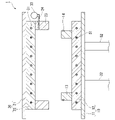
- FIG. 1 is a partially cutaway front view of a press.
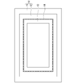
- FIG. 2 is a plan view showing the lower plate portion of the press.
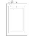
- FIG. 3 is a plan view (seen from below) showing the upper plate portion of the press.
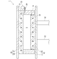
- FIG. 4 is a partially cutaway front view of the press.
- FIG. 5 is a partially cutaway front view of the press.
- FIG. 6 is a partially cutaway front view of the press.
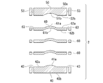
- FIG. 7 shows a portable mold.
- FIG. 8 shows a portable mold.
- FIG. 9 shows a portable mold.
- FIG. 10 is a partially cutaway front view showing a state in which the charged portable mold is pressed by a press.
- FIG. 11 is a drawing for explaining manufacturing steps included in the manufacturing method according to the embodiment.
- FIG. 12A and 12B are diagrams for explaining manufacturing steps included in the manufacturing method according to the embodiment.
- 13A and 13B are diagrams for explaining manufacturing steps included in the manufacturing method according to the embodiment.
- 14A and 14B are diagrams for explaining manufacturing steps included in the manufacturing method according to the embodiment.
- FIG. 15 is a drawing showing the relationship between the height of the workbench, the height of the loading platform of the cart, and the height of the upper surface of the lower heating platen of the press machine.
- Molding System One embodiment of the present invention relates to a molding system for producing compression molded articles (hereinafter also referred to simply as "molded articles") from thermoset resin materials.
- a molding system according to an embodiment includes a press and at least one portable mold.
- FIG. 1 shows an example of a press machine that can constitute a molding system according to an embodiment.
- the press machine 1 includes a lower plate portion 10, an upper plate portion 20 disposed above the lower plate portion 10 so as to face the lower plate portion 10, and the lower plate portion 10 and the upper plate portion 20.
- a pressurizing mechanism (only the cylinder 32 of the pressurizing mechanism is shown in FIG. 1) is provided for moving them in a direction to bring them closer together.
- the lower plate portion 10 is composed of a horizontally arranged lower substrate 11 and a lower heating platen 12 attached to the upper surface side of the lower substrate 11 .
- the upper plate portion 20 is composed of a horizontally arranged upper substrate 21 and an upper heating plate 22 attached to the lower surface side of the upper substrate 21 .
- FIG. 1 illustration of a frame for fixing the upper plate portion 20 and the like is omitted.
- the pressurizing mechanism is preferably hydraulic because the pressure can be easily controlled.
- the cylinder 32 of the pressure mechanism may be arranged to act on the upper plate portion 20 instead of the lower plate portion 10 .
- a heater 31 is built in each of the lower heating plate 12 and the upper heating plate 22 . Examples of heater 31 include, but are not limited to, steam heaters, oil heaters, electric heaters, and electromagnetic induction heaters.
- An annular lower wall member 13 is fixed to the upper surface of the lower heating platen 12 .
- the lower wall member 13 has a structure in which four vertical walls perpendicular to the upper surface of the lower heating plate 12 are connected to form a rectangular ring. It is arranged slightly inside the peripheral surface of the board 12 .
- the lower heating plate 12 and the lower wall member 13 may be seamlessly integrated.
- the lower wall member 13 is provided with a groove extending around its outer peripheral surface, and a vacuum sealing ring 14 is fitted in the groove.
- An annular upper wall member 23 is fixed to the lower surface of the upper heating plate 22 .
- the upper wall member 23 has a structure in which four vertical walls perpendicular to the lower surface of the upper heating plate 22 are connected to form a rectangular ring. and are arranged along the peripheral surface of the upper heating plate 22 .
- the upper heating plate 22 and the upper wall member 23 may be seamlessly integrated.
- the upper wall member 23 is provided with an exhaust hole 24 passing through one of the vertical walls.
- the exhaust hole 24 is connected to a vacuum pump 33 .
- the lower wall member 13 may be omitted and the lower heating platen 12 and the upper wall member 23 may be fitted together via the vacuum sealing ring 14 .
- the lower plate portion 10 and the upper plate portion 20 are brought close to each other, a closed space S surrounded by the lower heating plate 12, the upper heating plate 22 and the upper wall member 23 is formed.
- a lower wall member 13 and an upper wall member 23, which are fitted together via a vacuum sealing ring, are fixed to the upper surface of the lower substrate 11 and the lower surface of the upper substrate 21, respectively.
- the upper wall member 23 is arranged so as to surround the upper heating plate 22 .
- a closed space S surrounded by the lower substrate 11, the lower wall member 13, the upper substrate 21 and the upper wall member 23 is formed.
- FIG. 7 shows an example of a portable mold that constitutes the molding system according to the embodiment.
- the portable mold 2 consists of a bottom plate 40 , a top plate 50 and three intermediate plates 60 .
- the planar shape of each plate is, for example, a rectangle. Handles can be attached to the sides of any plate if desired. All plates have the same contour shape and dimensions in plan view and can be superimposed on each other.
- the lowermost plate 40 and the intermediate plate 60 directly above it are stacked.
- one and the other of the plates that are adjacent when stacked in the correct order are provided with an alignment protrusion and an alignment recess, respectively, so that the two plates only fit together when they are stacked such that they are exactly on top of each other. You may do so.
- Each plate has two pin holes. After stacking the plates, two pins 3 are inserted into the pin holes 53 of the uppermost plate 50 as shown in FIG. , through the pin holes 63 of the intermediate plate 60 and into the pin holes 43 of the bottom plate 40 .
- the number of intermediate plates that the portable mold can have is not limited to three, and may be two or less or three or more.
- the portable mold can be configured with only the bottom plate and the top plate without using the intermediate plate.
- Both the bottom surface 40b of the bottom plate 40 and the top surface 50a of the top plate 50 are entirely flat.
- the upper surface 40a of the lowermost plate 40, the lower surface 50b of the uppermost plate 50, the upper surface 60a and the lower surface 60b of each intermediate plate 60, respectively, have first regions 41a, 51b, 61a, 61b approximately in the center of each surface, and , has second regions 42a, 52b, 62a, 62b around the first region.
- the first area of each face is the area that will become the inner surface of the mold cavity when the plates are stacked. Accordingly, the first region 41a of the upper surface of the bottom plate and the first region 61a of the upper surface of each intermediate plate have a shape complementary to one surface of the molded article to be manufactured, and the first region of the lower surface of the top plate has a shape complementary to that of one surface. 51b and the first region 61b of the lower surface of each intermediate plate have a shape complementary to the other surface of the molded article to be produced.
- a second region of each face is flat.
- a second region 42a of the top surface of the bottom plate is parallel to the bottom surface 40b of the bottom plate, and a second region 52b of the bottom surface of the top plate is parallel to the top surface 50a of the top plate.
- the second region 62a on the upper surface and the second region 62b on the lower surface of each intermediate plate 60 are parallel to each other.
- both pin holes are formed through a second region that the plate has on its top and/or bottom surface.
- the portable mold according to the preferred embodiment multiple molding cavities are formed between any adjacent plates when all the plates are stacked.
- the portable mold 2 shown in FIG. 9 has nine first regions on the top surface of the bottom plate 40, the top and bottom surfaces of each of the two intermediate plates 60, and the bottom surface of the top plate 50. ing. When these plates are stacked, between the bottom plate 40 and the lower intermediate plate 60, between the two intermediate plates 60, and between the upper intermediate plate 60 and the top plate 50, 9 Individual mold cavities are formed. Therefore, if this portable mold is used, 27 (9 ⁇ 3) pieces of compression-molded products P can be obtained by one-time molding.
- At least part of the plate that constitutes the portable mold may be split into two or more.
- at least some of the plates may have an insert structure and consist of a matrix and a nest.
- the portable mold may include a set core in addition to the bottom plate, top plate and middle plate. Placement cores are used when manufacturing moldings with undercuts.
- a portable mold 2 charged with a thermosetting resin material M is placed in a closed space S formed in the press machine 1 described above, and pressed by a lower plate portion 10 and an upper plate portion 20. Show where you are pressing. Since the lower heating plate 12 and the upper heating plate 22 are exposed in the lower plate portion 10 and the upper plate portion 20 respectively, the portable mold 2 is in direct contact with the lower heating plate 12 and the upper heating plate 22 . Since the lower surface (lower surface 40b of the lowermost plate) and the upper surface (upper surface 50a of the uppermost plate) are flat, the contact with the respective lower heating plate 12 and upper heating plate 22 is planar. On the other hand, the sides of the portable mold 2 are in contact with neither the lower wall member 13 nor the upper wall member 23 . In other words, the sides of the portable mold 2 are surrounded by spaces.
- the resin material M is melted in the molding cavity of the portable mold 2, and part of the melted resin flows through the gap between the plates forming the molding cavity and flows into the portable mold 2. Acts as a trap to prevent resin material M from entering the vacuum line if it leaks out of the .
- the space between the side of the portable mold 2 and the lower wall member 13 and the upper wall member 23 is also advantageous in that the operation of placing the portable mold 2 inside these side wall members is facilitated. is.
- Examples of materials for portable molds include carbon steel and alloy steel (steel to which chromium, molybdenum, tungsten, vanadium, etc. are added) that have traditionally been used as steel materials for plastic molding.
- each plate that constitutes the portable mold 2 normally does not have a heat source inside.
- a heat source for heating the resin material M is a heater 31 built in each of the lower heating plate 12 and the upper heating plate 22 . Therefore, it is desirable to facilitate heat transfer from the lower heating plate 12 and the upper heating plate 22 to the resin material M through the portable mold 2 in order to cure the resin material M in a shorter time.
- the material of the portable mold 2 may be an aluminum alloy or a copper alloy such as beryllium copper, which has higher thermal conductivity than steel. These alloys have a high thermal conductivity of 100 W/(m ⁇ K) or more at 20°C. Aluminum alloys are particularly preferred due to their high thermal conductivity and light weight. The specific gravity at 20° C. is around 7.9 for steel materials and exceeds 8 for beryllium copper, whereas aluminum alloys are usually 2.7 to 2.8.
- Examples of aluminum alloys include 7000 series aluminum alloys (Al-Zn-Mg alloys), which are said to have the highest strength among aluminum alloys, and 2000 series aluminum alloys (Al-Cu alloys), which have strength comparable to steel materials. ), including but not limited to.
- the thermal conductivity of aluminum alloys varies depending on the refining, but the thermal conductivity at 20°C is 130 to 190 W/(m K) for A2017 (duralumin), 150 W/(m K) for A7003, and 150 W/(m K) for A7075 (exceeding Super duralumin) is said to be 130 W/(m ⁇ K).
- the weight of the portable mold 2 can be, for example, 2 kg or more and 30 kg or less. A weight within this range is convenient for transporting the portable mold. However, the weight of the portable mold is not limited within this range. If a power-equipped transport mechanism is introduced, a portable mold weighing nearly 200 kg can be used.
- the molding system according to the embodiment may further include a workbench as a component other than the press and the portable mold.
- the workbench can be used not only for charging the portable mold 2 with the resin material M, but also for removing the compression-molded product P from the portable mold 2 . These operations can be performed using the same workbench or different workbench.
- a molding system according to embodiments may further include a carriage for transporting the portable mold 2 . For preferred aspects of the workbench and carriage, see 2. below. section.
- a molding system may include at least one of each component.
- the molding system includes at least two portable dies per press.
- the at least two transportable molds may include a plurality of transportable molds with the same cavity shape, or may include transportable molds with mutually different cavity shapes.
- the number of transportable molds per press machine is described in 3. below. In the continuous production described in the section, it is preferable that the number is more than the required number so that the press machine does not have a waiting time due to shortage of portable dies. If each plate of the portable mold has an insert structure and the shape of the cavity can be changed by exchanging the inserts, it is possible to manufacture molded products of various shapes using a single portable mold. , the number of transportable dies required can be reduced.
- Another embodiment of the invention relates to a method of making compression molded articles.
- the above 1. The molding system described in Section 1 above can preferably be used.
- a manufacturing method according to an embodiment typically includes the following steps.
- First step outside the press, a portable die is charged with a thermosetting resin material (Fig. 11).
- Second step The portable mold charged in the first step is sandwiched between the lower heating platen and the upper heating platen preheated to the molding temperature of the press machine, and the surroundings are surrounded by a decompressible space (Fig. 12). ).
- Third step While reducing the pressure in the depressurizable space, the portable mold is further pressurized between the lower and upper heating plates maintained at the molding temperature to harden the resin material in the portable mold. .
- Fourth step Take out the portable mold from the press (Fig. 13).
- Fifth step Take out the compression-molded product from the portable mold (Fig. 14).
- thermosetting resin material (resin composition) M outside the press machine 1 .
- the resin material M may be placed in the portable mold 2 while being superimposed on a core material such as a honeycomb core or foam core.
- thermosetting resins that are blended as base resins in resin materials include epoxy resins, unsaturated polyester resins, acrylic resins, vinyl ester resins, phenol resins, and benzoxazine resins.
- the resin material may optionally contain various additives such as reactive diluents, release agents, defoaming agents, UV absorbers, and fillers.
- the resin material may be prepreg.
- a prepreg is a fiber reinforcement impregnated with a thermosetting matrix resin.
- the fibrous reinforcement consists of at least one fiber, each of which may be inorganic, organic or metallic.
- inorganic fibers include carbon fibers, silicon carbide fibers, alumina fibers, tungsten carbide fibers, boron fibers, and glass fibers.
- Inorganic fibers may be coated with metal.
- Organic fibers include aramid fibers, polyimide fibers, ultra-high molecular weight polyethylene fibers, nylon fibers, polyester fibers and the like.
- metal fibers include stainless fibers and iron fibers.
- a prepreg obtained by impregnating a fiber reinforcing material made of carbon fibers with a thermosetting resin composition, especially an epoxy resin composition, is one of the most preferable resin materials because it gives a lightweight and high-strength FRP by curing.
- prepreg examples include UD prepreg and woven prepreg.
- the basis weight of the fiber reinforcing material in these prepregs is preferably 50-800 g/m 2 , more preferably 75-300 g/m 2 .
- Textile prepregs include, for example, plain weave, twill weave, satin weave, triaxial weave, and the like.
- Other prepregs include SMC (sheet molding compound).
- a single layer of prepreg may be used, or a plurality of prepregs may be used by stacking them.
- a plurality of prepregs are stacked and used, only prepregs of the same kind may be laminated, or prepregs of different kinds may be laminated.
- UD prepregs are stacked and used, cross-ply lamination or angle-ply lamination is preferred.
- the woven fabric prepreg may be used only for the outermost layer so that a molded product having a surface through which the highly designed fabric can be seen through can be obtained.
- SMC can also be used overlaid with UD prepreg or woven prepreg.
- thermal grease may be applied to the contact surfaces between the adjacent plates in order to reduce the contact thermal resistance between the plates. Reduce the contact thermal resistance between the portable mold 2 and these heating plates when the portable mold 2 is sandwiched between the lower heating plate 12 and the upper heating plate 22 in the second step and the fourth step later.
- the lower surface 40b of the lowermost plate and the upper surface 50a of the uppermost plate of the portable mold 2 may be coated with thermal conductive grease.
- the work of charging the portable mold 2 with the resin material M is performed in a room at a temperature of 17 to 28° C. using a workbench with a top plate on which the plate of the portable mold can be stably placed. can be done.
- the temperature of the portable mold during charging can be the same as room temperature.
- a portable mold heated for the purpose of drying after washing may be charged before the temperature drops to room temperature, but wrinkles may occur during handling when the resin material is UD prepreg or textile prepreg.
- a low temperature of the portable mold during charging for example below 40° C. or even below 28° C., is necessary when charging takes a relatively long time due to the complexity of the shape of the part to be produced. It is advantageous to This is because there is no problem that the temperature of the resin material rises during charging and the tackiness increases, making handling difficult.
- the low temperature of the portable mold during charging is also advantageous when the duration of the first step is long because the portable mold has a large number of molding cavities. This is because the molded product obtained from the resin material placed in the portable mold immediately after the start of the first process and the molded product obtained from the resin material placed in the portable mold immediately before the end of the first process This is because there is substantially no difference in physical properties between them due to the difference in thermal history received in the first step.
- the portable mold 2 charged with the resin material M is preferably preheated prior to the second step. By preheating, the time for the subsequent fourth step can be shortened. Preheating is performed so that the viscosity of the resin material does not significantly decrease.
- the temperature of the portable mold after preheating is preferably 40° C. or higher and 80° C. or lower, and more preferably 60° C. or higher and 80° C. or lower. If the temperature of the portable mold is 80° C. or less, the mold can be touched with a gloved hand, so there is no problem in transportation.
- the portable mold charged on the workbench is transported to the heater as necessary, preheated, and then transported to the press for the second process.
- the transportation may be carried out manually or by using a trolley.
- the weight of the portable mold is large or when many portable molds are transported at once, it is preferable to use a trolley.
- the height of the platform of the trolley is preferably the same as the height of the workbench.
- the portable mold can be transferred from the workbench to the carriage simply by sliding it horizontally. Furthermore, if a roller conveyor is provided on the loading platform of the carriage, the transfer becomes easier.
- the height of the platform of the truck means the height of the lower surface of the portable mold (lower surface of the bottom plate) when the portable mold is appropriately placed on the platform.
- the height of the workbench refers to the height of the upper surface of the top surface of the workbench. Even if the height of the platform of the carriage and the height of the workbench are slightly different, if the difference is smaller than the thickness of the bottom plate of the portable mold, both heights can be regarded as the same.
- Second Step In the second step, as shown in FIG. 12, the portable mold 2 charged in the first step is placed between the lower heating platen 12 and the upper heating platen 22 of the press machine 1 preheated to the molding temperature. and surrounded by a closed space S.
- the reason why the lower heating platen 12 and the upper heating platen 22 of the press machine 1 are preliminarily heated to the molding temperature is to shorten the time required for the subsequent fourth step.
- the molding temperature can be 110° C. to 130° C., 130° C. to 135° C., 135° C. to 145° C., 145° C. to 150° C., 150° C. to 180° C., and the like.
- the lower plate portion 10 and the upper plate portion 20 are separated until the upper surface of the portable mold (the upper surface 50 a of the top plate) contacts the upper heating platen 22 . bring closer.
- the lower wall member 13 and the upper wall member 23, which are annular, are fitted together via the vacuum sealing ring 14, and a closed space S that can be decompressed is formed around the portable mold 2.
- the surface pressure that the portable mold 2 receives is preferably about 1 to 15 mPa.
- Third step In the third step, the closed space S formed around the portable mold 2 in the second step is decompressed, and the pressure is reduced between the lower heating platen 12 and the upper heating platen 22 maintained at the molding temperature.
- the transport mold is further pressurized to harden the resin material M in the transport mold 2 .
- the closed space S is decompressed by operating the vacuum pump 33 so that the pressure after decompression is preferably 0.1 Pa or less, more preferably 0.01 Pa or less.
- the pressurization of the portable mold 2 is performed so that the surface pressure is preferably in the range of 1 to 15 MPa.
- the pressurization may be started at the same time as the pressure reduction of the closed space S is started, or may be after.
- pressurization may be started before or after the closed space S is sufficiently depressurized.
- the purpose of reducing the pressure in the closed space S is to deaerate the resin material M and obtain a void-free compression-molded product P. Therefore, it is desirable that the closed space S is sufficiently decompressed before the resin material M gels. This is because a resin material whose viscosity has increased significantly due to gelation is difficult to deaerate.
- the time for the third step is set to a time sufficient for the resin material M to harden to the required degree.
- the curing characteristics of the resin material, the size of the compression-molded product to be manufactured, the molding temperature, the material of the portable mold, the number of plates included in the portable mold, etc., should be taken into account, Can be determined by error.
- the portable mold 2 is removed from the press machine 1 .
- the transportable mold 2 that has been taken out is transported onto the workbench.
- the workbench may be the same as that used in the first step, or it may be different.
- Transportation may be performed manually or by using a trolley.
- the lower wall member 13 of the press machine 1 since the upper end of the lower wall member 13 of the press machine 1 is higher than the upper surface of the lower heating platen 12, when the portable mold 2 is transferred from the lower heating platen 12 to the carriage, the lower wall member It is necessary to lift above the top of 13.
- the mold 2 can be easily transferred from the lower heating platen 12 to the carriage.
- the portable mold can be transferred from the lower heating plate to the truck simply by horizontally sliding it. If the height of the loading platform of the truck is the same as that of the workbench, it is only necessary to horizontally slide the portable mold from the truck to the workbench.
- the compression-molded product P is taken out from the portable mold 2 . It is preferable to forcibly cool the compression-molded product P immediately after taking it out of the portable mold 2 while taking care not to deform it.
- Portable molds are also preferably forced to cool immediately after removal of the compression molded article for use in the next molding cycle. The forced cooling of the portable mold 2 can also be performed before the compression-molded product P is taken out.
- a plurality of charged portable molds are arranged side by side between the lower heating platen and the upper heating platen of one press machine, and in the third step, the plurality of portable molds may be pressurized at the same time.
- a plurality of charged portable molds are vertically stacked between the lower heating platen and the upper heating platen of one press machine, and in the third step, the plurality of of portable molds may be pressurized at the same time.
- the portable mold can be easily remounted by simply horizontally sliding it between the lower heating plate 12 and the carriage 72 and between the carriage 72 and the workbench 71.
- the height of the upper surface of the lower heating plate should be adjusted to the height of the workbench.
- a lift truck to transport the portable mold.
- different portable molds with different cavity shapes can be used for the Nth molding cycle and the (N+1)th molding cycle.
- the second step of the (N+1)th molding cycle can be performed while the lower substrate and the upper substrate of the press machine are maintained at the molding temperature without being cooled. Therefore, it is possible to produce various molded products in small quantities with high efficiency.
- Embodiments of the invention include the following.
- a molding system for manufacturing a compression-molded product from a thermosetting resin material comprising a press and one or more portable molds, the press having a lower a lower plate portion including a heating plate; an upper plate portion including an upper heating plate; and at least one annular side wall member each fixed to the lower plate portion or the upper plate portion, and a closed space surrounded by the lower plate portion, the upper plate portion, and the at least one side wall member, which can be depressurized, is formed when the plate portion and the upper plate portion are brought closer to each other;
- a molding system which is a pressing machine in which at least one portable mold is arranged in a space so that pressure can be applied between the lower plate portion and the upper plate portion.
- the closed space is defined by an annular lower wall member fixed to the lower plate portion and an annular upper wall member fixed to the upper plate portion, or an annular lower wall member fixed to the lower plate portion. and the upper heating plate, or alternatively, the upper wall member fixed to the upper plate portion and the lower heating plate may be formed by fitting together via a vacuum sealing ring.
- the at least one sidewall member of the press comprises a sidewall member secured to the top plate portion.
- the at least one side wall member of the press includes a side wall member provided with an exhaust port, the exhaust port being connected to a vacuum pump.
- the portable mold is composed of a plurality of plates including a bottom plate having a flat bottom surface and a top plate having a flat top surface, and the bottom plate and the top plate are respectively located at the bottom. and when the plurality of plates are stacked on top, the bottom surface of the bottom plate and the top surface of the top plate are parallel to each other, and there is at least one molding cavity between any adjacent plates A molding system according to any of embodiments 1-3, formed.
- Embodiment 5 The molding system according to Embodiment 4, wherein said plurality of plates includes said bottom plate and said top plate plus at least one intermediate plate.
- Embodiment 6 Any one of Embodiments 1 to 5, wherein the material of the portable mold is an aluminum alloy that may be 2000 series or 7000 series, or may be A2017, A7003 or A7075. molding system.
- Embodiment 7 The molding system according to any one of Embodiments 1 to 6, wherein the weight of the portable mold is 2 kg or more and 30 kg or less.
- the at least one portable mold can be arranged in the closed space so as not to contact any of the at least one side wall member. molding system.
- Each of the lower heating platen and the upper heating platen is in direct and surface contact with at least one of the portable molds pressurized by the lower plate portion and the upper plate portion.
- Embodiment 12 The molding system according to any one of Embodiments 1 to 11, further comprising a workbench used for taking out the compression-molded product from the portable mold.
- Embodiment 13 The molding system according to any one of Embodiments 1 to 12, further comprising a carriage for transporting the portable mold.
- Embodiment 14 A molding system according to Embodiment 13, wherein the carriage is a lifting carriage.
- the first workbench includes a first workbench used for charging the portable mold with the resin material, and a carriage for transporting the portable mold. 11.
- the height of the carriage and the height of the carriage bed are the same.
- a second workbench used for taking out the compression-molded product from the portable mold is included, and the height of the first workbench and the height of the second workbench are the same.
- a molding system according to Embodiment 15. [Embodiment 17] The height of the upper surface of the lower heating plate of the press machine is fixed at the same height as the loading platform of the carriage, and the portable mold is horizontally slid to lift the lower heating plate. 17.
- Embodiment 18 A method for manufacturing a compression-molded article, wherein the molding system according to any one of Embodiments 1 to 17 is used to manufacture a compression-molded article from a thermosetting resin material.
- Embodiment 19 A first step of charging a portable mold with a thermosetting resin material outside the press; A second step of sandwiching between a lower heating plate and an upper heating plate preheated to a molding temperature and surrounding the surroundings with a pressure-reducing space; depressurizing the pressure-reducing space and the lower heat maintained at the molding temperature A third step of further pressurizing the portable mold between the platen and the upper heating plate to harden the resin material in the portable mold; a fourth step of removing the portable mold from the press machine.
- Embodiment 20 A manufacturing method according to Embodiment 19, wherein the first step is performed in a room at a temperature of 17 to 28°C.
- Embodiment 21 The manufacturing method according to Embodiment 20, wherein the temperature of the portable mold in the first step is 40°C or less and may be the same as the temperature in the chamber.
- the portable mold is composed of a plurality of plates including a bottom plate having a flat bottom surface and a top plate having a flat top surface, and the bottom plate and the top plate are respectively located at the bottom.
- Embodiment 23 The method of Embodiment 22, wherein said plurality of plates comprises said bottom plate and said top plate plus at least one intermediate plate.
- Embodiment 24 The manufacturing method according to Embodiment 22 or 23, wherein the material of the portable mold is an aluminum alloy that may be 2000 series or 7000 series, or may be A2017, A7003 or A7075. .
- Embodiment 25 The manufacturing method according to any one of Embodiments 22 to 24, wherein the weight of the portable mold is 2 kg or more and 30 kg or less.
- Embodiment 26 The manufacturing method according to any one of Embodiments 22 to 25, wherein in the first step, heat-conducting grease is applied to contact surfaces between adjacent plates.
- Embodiment 27 The manufacturing method according to any one of Embodiments 22 to 26, wherein the bottom surface of the bottom plate and the top surface of the top plate are coated with heat conductive grease before the second step.
- each of the lower heating platen and the upper heating platen is directly connected to at least one of the portable molds pressurized between the lower heating platen and the upper heating platen. and in surface contact.
- the depressurizable space is depressurized to 0.1 Pa or less, preferably 0.01 Pa or less, and the portable mold is pressurized with a surface pressure within the range of 1 to 15 MPa. 29.
- the manufacturing method according to any one of embodiments 19-28.
- the press includes a lower plate portion including the lower heating plate and an upper plate portion including the upper heating plate, each of which is fixed to the lower plate portion or the upper plate portion and has an annular shape. and at least one side wall member, and is decompressible surrounded by the lower plate portion, the upper plate portion, and the at least one side wall member when the lower plate portion and the upper plate portion are brought close to each other.
- N is an integer of 1 or more
- the 32 is any one of embodiments 19 to 31, wherein the molding cycle is repeated so as to perform the second step of the (N+1)th molding cycle while maintaining the lower heating platen and the upper heating platen at the molding temperature without cooling.
- the manufacturing method which concerns.
- Embodiment 33 The manufacturing method according to Embodiment 32, wherein the portable mold used in the Nth molding cycle is different from the portable mold used in the (N+1)th molding cycle.
- Embodiment 34 According to embodiment 33, wherein the portable mold used in the Nth molding cycle and the portable mold used in the (N+1)th molding cycle have molding cavities of different shapes. The manufacturing method which concerns.
- Embodiment 35 The manufacturing method according to any one of Embodiments 19 to 34, wherein the resin material is prepreg.
Landscapes
- Engineering & Computer Science (AREA)
- Mechanical Engineering (AREA)
- Chemical & Material Sciences (AREA)
- Composite Materials (AREA)
- Casting Or Compression Moulding Of Plastics Or The Like (AREA)
- Moulds For Moulding Plastics Or The Like (AREA)
Priority Applications (1)
| Application Number | Priority Date | Filing Date | Title |
|---|---|---|---|
| JP2023511383A JP7843275B2 (ja) | 2021-03-31 | 2022-03-29 | 成形システム及び圧縮成形品の製造方法 |
Applications Claiming Priority (2)
| Application Number | Priority Date | Filing Date | Title |
|---|---|---|---|
| JP2021059523 | 2021-03-31 | ||
| JP2021-059523 | 2021-03-31 |
Publications (1)
| Publication Number | Publication Date |
|---|---|
| WO2022210719A1 true WO2022210719A1 (ja) | 2022-10-06 |
Family
ID=83456367
Family Applications (1)
| Application Number | Title | Priority Date | Filing Date |
|---|---|---|---|
| PCT/JP2022/015471 Ceased WO2022210719A1 (ja) | 2021-03-31 | 2022-03-29 | 成形システム及び圧縮成形品の製造方法 |
Country Status (2)
| Country | Link |
|---|---|
| JP (1) | JP7843275B2 (https=) |
| WO (1) | WO2022210719A1 (https=) |
Citations (6)
| Publication number | Priority date | Publication date | Assignee | Title |
|---|---|---|---|---|
| JPS6447517A (en) * | 1987-08-18 | 1989-02-22 | Nec Corp | Preparation of multilayered printed-circuit board |
| JPH0732400A (ja) * | 1993-07-23 | 1995-02-03 | Seiichiro Yamagami | 真空加硫成形機 |
| JP2007090851A (ja) * | 2005-09-05 | 2007-04-12 | Komatsu Sanki Kk | プレス成形装置 |
| JP2009113369A (ja) * | 2007-11-07 | 2009-05-28 | Fukui Prefecture | 熱可塑性樹脂複合材料成形品の成形方法 |
| JP2016155356A (ja) * | 2015-02-26 | 2016-09-01 | 富士通株式会社 | 金型搬送装置及び金型搬送方法 |
| WO2019097969A1 (ja) * | 2017-11-17 | 2019-05-23 | 三菱重工業株式会社 | 成形装置 |
-
2022
- 2022-03-29 JP JP2023511383A patent/JP7843275B2/ja active Active
- 2022-03-29 WO PCT/JP2022/015471 patent/WO2022210719A1/ja not_active Ceased
Patent Citations (6)
| Publication number | Priority date | Publication date | Assignee | Title |
|---|---|---|---|---|
| JPS6447517A (en) * | 1987-08-18 | 1989-02-22 | Nec Corp | Preparation of multilayered printed-circuit board |
| JPH0732400A (ja) * | 1993-07-23 | 1995-02-03 | Seiichiro Yamagami | 真空加硫成形機 |
| JP2007090851A (ja) * | 2005-09-05 | 2007-04-12 | Komatsu Sanki Kk | プレス成形装置 |
| JP2009113369A (ja) * | 2007-11-07 | 2009-05-28 | Fukui Prefecture | 熱可塑性樹脂複合材料成形品の成形方法 |
| JP2016155356A (ja) * | 2015-02-26 | 2016-09-01 | 富士通株式会社 | 金型搬送装置及び金型搬送方法 |
| WO2019097969A1 (ja) * | 2017-11-17 | 2019-05-23 | 三菱重工業株式会社 | 成形装置 |
Also Published As
| Publication number | Publication date |
|---|---|
| JP7843275B2 (ja) | 2026-04-09 |
| JPWO2022210719A1 (https=) | 2022-10-06 |
Similar Documents
| Publication | Publication Date | Title |
|---|---|---|
| US6855917B2 (en) | Induction processable ceramic die with durable die liner | |
| US5567499A (en) | Resin transfer molding in combination with honeycomb core | |
| JP6041430B2 (ja) | 炭素繊維複合成形品のプレス成形装置、炭素繊維複合成形品のプレス成形システム、および炭素繊維複合成形品のプレス方法 | |
| CN101484291B (zh) | 使用模塑芯制备纤维复合材料部件的方法及该模塑芯 | |
| US5066351A (en) | Hot/cold press forming methods for shaping thermoformable materials | |
| US20180229406A1 (en) | Method for molding fiber-reinforced plastic, and molding device for same | |
| JP2009542483A (ja) | 複合部品の製造方法 | |
| CN104797407A (zh) | 金属/cfrp复合结构及其制造方法和制造设备 | |
| EP2842711B1 (en) | Apparatus and method for producing a composite material aircraft component | |
| TW201304940A (zh) | 纖維強化樹脂與輕量化芯部之複合材料及製造其之方法與裝置 | |
| WO2022210719A1 (ja) | 成形システム及び圧縮成形品の製造方法 | |
| KR102286766B1 (ko) | 복합소재 성형장치 | |
| KR102485826B1 (ko) | 복합소재 성형장치 | |
| US4701293A (en) | Molding process and apparatus utilizing memory metal alloy springs | |
| JP2018024097A (ja) | 繊維強化樹脂成形体の製造方法 | |
| JP6712430B1 (ja) | 熱可塑性繊維強化樹脂成形品の製造方法 | |
| CN114311731A (zh) | 耐高温双马树脂基复合材料分段固化成型的方法 | |
| JPWO2017061146A1 (ja) | 繊維強化複合部材の成形装置 | |
| JP5762694B2 (ja) | 賦形成形方法及び繊維強化樹脂成形品 | |
| KR102529929B1 (ko) | 복합 소재 제조 시스템 및 방법 | |
| WO2019097969A1 (ja) | 成形装置 | |
| EP4289604B1 (en) | Composite manufacturing method | |
| JP2011208039A (ja) | 賦形成形方法及び繊維強化樹脂成形品 | |
| JP6724335B2 (ja) | 熱硬化性の樹脂を用いた樹脂成形品の成形方法および成形装置 | |
| JP2025118309A (ja) | 成形方法及び成形装置 |
Legal Events
| Date | Code | Title | Description |
|---|---|---|---|
| 121 | Ep: the epo has been informed by wipo that ep was designated in this application |
Ref document number: 22780930 Country of ref document: EP Kind code of ref document: A1 |
|
| WWE | Wipo information: entry into national phase |
Ref document number: 2023511383 Country of ref document: JP |
|
| NENP | Non-entry into the national phase |
Ref country code: DE |
|
| 122 | Ep: pct application non-entry in european phase |
Ref document number: 22780930 Country of ref document: EP Kind code of ref document: A1 |