WO2022210719A1 - 成形システム及び圧縮成形品の製造方法 - Google Patents
成形システム及び圧縮成形品の製造方法 Download PDFInfo
- Publication number
- WO2022210719A1 WO2022210719A1 PCT/JP2022/015471 JP2022015471W WO2022210719A1 WO 2022210719 A1 WO2022210719 A1 WO 2022210719A1 JP 2022015471 W JP2022015471 W JP 2022015471W WO 2022210719 A1 WO2022210719 A1 WO 2022210719A1
- Authority
- WO
- WIPO (PCT)
- Prior art keywords
- plate portion
- portable
- portable mold
- molding
- mold
- Prior art date
Links
- 238000000465 moulding Methods 0.000 title claims abstract description 117
- 238000004519 manufacturing process Methods 0.000 title claims abstract description 60
- 238000000034 method Methods 0.000 title claims description 10
- 239000000463 material Substances 0.000 claims abstract description 63
- 229920005989 resin Polymers 0.000 claims abstract description 55
- 239000011347 resin Substances 0.000 claims abstract description 55
- 229920001187 thermosetting polymer Polymers 0.000 claims abstract description 17
- 238000010438 heat treatment Methods 0.000 claims description 110
- 229910000838 Al alloy Inorganic materials 0.000 claims description 12
- 230000006835 compression Effects 0.000 claims description 9
- 238000007906 compression Methods 0.000 claims description 9
- 239000004519 grease Substances 0.000 claims description 6
- 238000001816 cooling Methods 0.000 claims description 4
- 239000004634 thermosetting polymer Substances 0.000 claims description 2
- 239000000835 fiber Substances 0.000 description 16
- 239000000758 substrate Substances 0.000 description 12
- 229910000831 Steel Inorganic materials 0.000 description 7
- 230000007246 mechanism Effects 0.000 description 7
- 238000007789 sealing Methods 0.000 description 7
- 239000010959 steel Substances 0.000 description 7
- 239000011162 core material Substances 0.000 description 5
- 229920002430 Fibre-reinforced plastic Polymers 0.000 description 4
- 239000011151 fibre-reinforced plastic Substances 0.000 description 4
- 230000004048 modification Effects 0.000 description 4
- 238000012986 modification Methods 0.000 description 4
- 239000003677 Sheet moulding compound Substances 0.000 description 3
- 229910045601 alloy Inorganic materials 0.000 description 3
- 239000000956 alloy Substances 0.000 description 3
- 230000000295 complement effect Effects 0.000 description 3
- 238000010924 continuous production Methods 0.000 description 3
- 238000010586 diagram Methods 0.000 description 3
- 230000002093 peripheral effect Effects 0.000 description 3
- 239000012779 reinforcing material Substances 0.000 description 3
- 239000011342 resin composition Substances 0.000 description 3
- 230000037303 wrinkles Effects 0.000 description 3
- 229920000049 Carbon (fiber) Polymers 0.000 description 2
- 229910000975 Carbon steel Inorganic materials 0.000 description 2
- 229910000737 Duralumin Inorganic materials 0.000 description 2
- XEEYBQQBJWHFJM-UHFFFAOYSA-N Iron Chemical compound [Fe] XEEYBQQBJWHFJM-UHFFFAOYSA-N 0.000 description 2
- DMFGNRRURHSENX-UHFFFAOYSA-N beryllium copper Chemical compound [Be].[Cu] DMFGNRRURHSENX-UHFFFAOYSA-N 0.000 description 2
- 239000004917 carbon fiber Substances 0.000 description 2
- 239000010962 carbon steel Substances 0.000 description 2
- 239000003795 chemical substances by application Substances 0.000 description 2
- 239000003822 epoxy resin Substances 0.000 description 2
- 239000012784 inorganic fiber Substances 0.000 description 2
- 238000003475 lamination Methods 0.000 description 2
- 239000011159 matrix material Substances 0.000 description 2
- 229910052751 metal Inorganic materials 0.000 description 2
- 239000002184 metal Substances 0.000 description 2
- 238000010137 moulding (plastic) Methods 0.000 description 2
- 229920000647 polyepoxide Polymers 0.000 description 2
- 238000003825 pressing Methods 0.000 description 2
- 230000002787 reinforcement Effects 0.000 description 2
- 239000004753 textile Substances 0.000 description 2
- CMLFRMDBDNHMRA-UHFFFAOYSA-N 2h-1,2-benzoxazine Chemical compound C1=CC=C2C=CNOC2=C1 CMLFRMDBDNHMRA-UHFFFAOYSA-N 0.000 description 1
- 239000004925 Acrylic resin Substances 0.000 description 1
- 229920000178 Acrylic resin Polymers 0.000 description 1
- 229910000851 Alloy steel Inorganic materials 0.000 description 1
- 229910018182 Al—Cu Inorganic materials 0.000 description 1
- 229910018571 Al—Zn—Mg Inorganic materials 0.000 description 1
- ZOXJGFHDIHLPTG-UHFFFAOYSA-N Boron Chemical compound [B] ZOXJGFHDIHLPTG-UHFFFAOYSA-N 0.000 description 1
- VYZAMTAEIAYCRO-UHFFFAOYSA-N Chromium Chemical compound [Cr] VYZAMTAEIAYCRO-UHFFFAOYSA-N 0.000 description 1
- 229910000881 Cu alloy Inorganic materials 0.000 description 1
- ZOKXTWBITQBERF-UHFFFAOYSA-N Molybdenum Chemical compound [Mo] ZOKXTWBITQBERF-UHFFFAOYSA-N 0.000 description 1
- 239000004642 Polyimide Substances 0.000 description 1
- 239000004699 Ultra-high molecular weight polyethylene Substances 0.000 description 1
- 239000006096 absorbing agent Substances 0.000 description 1
- 239000000654 additive Substances 0.000 description 1
- PNEYBMLMFCGWSK-UHFFFAOYSA-N aluminium oxide Inorganic materials [O-2].[O-2].[O-2].[Al+3].[Al+3] PNEYBMLMFCGWSK-UHFFFAOYSA-N 0.000 description 1
- 239000002518 antifoaming agent Substances 0.000 description 1
- 239000004760 aramid Substances 0.000 description 1
- 229920006231 aramid fiber Polymers 0.000 description 1
- 229910052796 boron Inorganic materials 0.000 description 1
- QHIWVLPBUQWDMQ-UHFFFAOYSA-N butyl prop-2-enoate;methyl 2-methylprop-2-enoate;prop-2-enoic acid Chemical compound OC(=O)C=C.COC(=O)C(C)=C.CCCCOC(=O)C=C QHIWVLPBUQWDMQ-UHFFFAOYSA-N 0.000 description 1
- 229910052804 chromium Inorganic materials 0.000 description 1
- 239000011651 chromium Substances 0.000 description 1
- VNTLIPZTSJSULJ-UHFFFAOYSA-N chromium molybdenum Chemical compound [Cr].[Mo] VNTLIPZTSJSULJ-UHFFFAOYSA-N 0.000 description 1
- 238000000748 compression moulding Methods 0.000 description 1
- 230000006837 decompression Effects 0.000 description 1
- 239000003085 diluting agent Substances 0.000 description 1
- 238000001035 drying Methods 0.000 description 1
- 230000005674 electromagnetic induction Effects 0.000 description 1
- 239000004744 fabric Substances 0.000 description 1
- 239000000945 filler Substances 0.000 description 1
- 239000006260 foam Substances 0.000 description 1
- 239000000499 gel Substances 0.000 description 1
- 238000001879 gelation Methods 0.000 description 1
- 239000003365 glass fiber Substances 0.000 description 1
- 230000005484 gravity Effects 0.000 description 1
- LNEPOXFFQSENCJ-UHFFFAOYSA-N haloperidol Chemical compound C1CC(O)(C=2C=CC(Cl)=CC=2)CCN1CCCC(=O)C1=CC=C(F)C=C1 LNEPOXFFQSENCJ-UHFFFAOYSA-N 0.000 description 1
- 229910052742 iron Inorganic materials 0.000 description 1
- 238000010030 laminating Methods 0.000 description 1
- 239000010410 layer Substances 0.000 description 1
- 239000000203 mixture Substances 0.000 description 1
- 229910052750 molybdenum Inorganic materials 0.000 description 1
- 239000011733 molybdenum Substances 0.000 description 1
- 229920001778 nylon Polymers 0.000 description 1
- 239000003921 oil Substances 0.000 description 1
- 239000005011 phenolic resin Substances 0.000 description 1
- 230000000704 physical effect Effects 0.000 description 1
- 229920000728 polyester Polymers 0.000 description 1
- 229920001721 polyimide Polymers 0.000 description 1
- 238000007670 refining Methods 0.000 description 1
- HBMJWWWQQXIZIP-UHFFFAOYSA-N silicon carbide Chemical compound [Si+]#[C-] HBMJWWWQQXIZIP-UHFFFAOYSA-N 0.000 description 1
- 229910010271 silicon carbide Inorganic materials 0.000 description 1
- 239000002356 single layer Substances 0.000 description 1
- 239000007858 starting material Substances 0.000 description 1
- 230000007723 transport mechanism Effects 0.000 description 1
- WFKWXMTUELFFGS-UHFFFAOYSA-N tungsten Chemical compound [W] WFKWXMTUELFFGS-UHFFFAOYSA-N 0.000 description 1
- 229910052721 tungsten Inorganic materials 0.000 description 1
- 239000010937 tungsten Substances 0.000 description 1
- UONOETXJSWQNOL-UHFFFAOYSA-N tungsten carbide Chemical compound [W+]#[C-] UONOETXJSWQNOL-UHFFFAOYSA-N 0.000 description 1
- 229920000785 ultra high molecular weight polyethylene Polymers 0.000 description 1
- 229920006337 unsaturated polyester resin Polymers 0.000 description 1
- 229910052720 vanadium Inorganic materials 0.000 description 1
- GPPXJZIENCGNKB-UHFFFAOYSA-N vanadium Chemical compound [V]#[V] GPPXJZIENCGNKB-UHFFFAOYSA-N 0.000 description 1
- 229920001567 vinyl ester resin Polymers 0.000 description 1
- 238000005406 washing Methods 0.000 description 1
- 238000005303 weighing Methods 0.000 description 1
- 239000002759 woven fabric Substances 0.000 description 1
Images


Classifications
-
- B—PERFORMING OPERATIONS; TRANSPORTING
- B29—WORKING OF PLASTICS; WORKING OF SUBSTANCES IN A PLASTIC STATE IN GENERAL
- B29C—SHAPING OR JOINING OF PLASTICS; SHAPING OF MATERIAL IN A PLASTIC STATE, NOT OTHERWISE PROVIDED FOR; AFTER-TREATMENT OF THE SHAPED PRODUCTS, e.g. REPAIRING
- B29C43/00—Compression moulding, i.e. applying external pressure to flow the moulding material; Apparatus therefor
- B29C43/02—Compression moulding, i.e. applying external pressure to flow the moulding material; Apparatus therefor of articles of definite length, i.e. discrete articles
-
- B—PERFORMING OPERATIONS; TRANSPORTING
- B29—WORKING OF PLASTICS; WORKING OF SUBSTANCES IN A PLASTIC STATE IN GENERAL
- B29C—SHAPING OR JOINING OF PLASTICS; SHAPING OF MATERIAL IN A PLASTIC STATE, NOT OTHERWISE PROVIDED FOR; AFTER-TREATMENT OF THE SHAPED PRODUCTS, e.g. REPAIRING
- B29C43/00—Compression moulding, i.e. applying external pressure to flow the moulding material; Apparatus therefor
- B29C43/32—Component parts, details or accessories; Auxiliary operations
- B29C43/56—Compression moulding under special conditions, e.g. vacuum
-
- B—PERFORMING OPERATIONS; TRANSPORTING
- B29—WORKING OF PLASTICS; WORKING OF SUBSTANCES IN A PLASTIC STATE IN GENERAL
- B29C—SHAPING OR JOINING OF PLASTICS; SHAPING OF MATERIAL IN A PLASTIC STATE, NOT OTHERWISE PROVIDED FOR; AFTER-TREATMENT OF THE SHAPED PRODUCTS, e.g. REPAIRING
- B29C70/00—Shaping composites, i.e. plastics material comprising reinforcements, fillers or preformed parts, e.g. inserts
- B29C70/04—Shaping composites, i.e. plastics material comprising reinforcements, fillers or preformed parts, e.g. inserts comprising reinforcements only, e.g. self-reinforcing plastics
- B29C70/06—Fibrous reinforcements only
-
- B—PERFORMING OPERATIONS; TRANSPORTING
- B29—WORKING OF PLASTICS; WORKING OF SUBSTANCES IN A PLASTIC STATE IN GENERAL
- B29C—SHAPING OR JOINING OF PLASTICS; SHAPING OF MATERIAL IN A PLASTIC STATE, NOT OTHERWISE PROVIDED FOR; AFTER-TREATMENT OF THE SHAPED PRODUCTS, e.g. REPAIRING
- B29C70/00—Shaping composites, i.e. plastics material comprising reinforcements, fillers or preformed parts, e.g. inserts
- B29C70/04—Shaping composites, i.e. plastics material comprising reinforcements, fillers or preformed parts, e.g. inserts comprising reinforcements only, e.g. self-reinforcing plastics
- B29C70/28—Shaping operations therefor
- B29C70/40—Shaping or impregnating by compression not applied
- B29C70/42—Shaping or impregnating by compression not applied for producing articles of definite length, i.e. discrete articles
-
- B—PERFORMING OPERATIONS; TRANSPORTING
- B29—WORKING OF PLASTICS; WORKING OF SUBSTANCES IN A PLASTIC STATE IN GENERAL
- B29K—INDEXING SCHEME ASSOCIATED WITH SUBCLASSES B29B, B29C OR B29D, RELATING TO MOULDING MATERIALS OR TO MATERIALS FOR MOULDS, REINFORCEMENTS, FILLERS OR PREFORMED PARTS, e.g. INSERTS
- B29K2101/00—Use of unspecified macromolecular compounds as moulding material
- B29K2101/10—Thermosetting resins
-
- B—PERFORMING OPERATIONS; TRANSPORTING
- B29—WORKING OF PLASTICS; WORKING OF SUBSTANCES IN A PLASTIC STATE IN GENERAL
- B29K—INDEXING SCHEME ASSOCIATED WITH SUBCLASSES B29B, B29C OR B29D, RELATING TO MOULDING MATERIALS OR TO MATERIALS FOR MOULDS, REINFORCEMENTS, FILLERS OR PREFORMED PARTS, e.g. INSERTS
- B29K2105/00—Condition, form or state of moulded material or of the material to be shaped
- B29K2105/06—Condition, form or state of moulded material or of the material to be shaped containing reinforcements, fillers or inserts
- B29K2105/08—Condition, form or state of moulded material or of the material to be shaped containing reinforcements, fillers or inserts of continuous length, e.g. cords, rovings, mats, fabrics, strands or yarns
Definitions
- the present invention relates to a molding system and method for manufacturing compression molded articles from thermosetting resin materials.
- This application claims priority based on Japanese Patent Application No. 2021-059523 filed in Japan on March 31, 2021, the content of which is incorporated herein.
- Fiber reinforced plastic is lightweight and has excellent mechanical properties, so it is widely used in sports and leisure applications, as well as industrial applications such as automobiles and aircraft.
- a molded article made of fiber-reinforced plastic can be manufactured by compression molding using prepreg as a starting material (Patent Document 1).
- the mold is heated to a temperature that allows the prepreg to be sufficiently cured before being charged with the prepreg.
- a multistage press is known for manufacturing a large number of molded plates made of a resin composition at once (Patent Document 2).
- the main object of the present invention is to provide a molding system and a manufacturing method for efficiently producing compression-molded articles with few voids using thermosetting resin materials.
- a molding system for manufacturing compression molded articles from thermosetting resin materials.
- the molding system consists of a press and at least one portable mold.
- the press includes a lower plate portion including a lower heating plate, an upper plate portion including an upper heating plate, and at least one ring-shaped plate portion each fixed to either the lower plate portion or the upper plate portion. and a side wall member, and when the lower plate portion and the upper plate portion are brought close to each other, a depressurizable closed space surrounded by the lower plate portion, the upper plate portion, and the at least one side wall member is formed. and the portable mold is arranged in the closed space so that the lower plate portion and the upper plate portion can be pressurized.
- a first step of charging a portable mold with a thermosetting resin material outside the press A second step of sandwiching between a lower heating plate and an upper heating plate preheated to the molding temperature of a press and surrounding it with a space that can be reduced in pressure; A third step of further pressurizing the portable mold between the lowered lower heating plate and the upper heating plate to harden the resin material in the portable mold; and a fifth step of removing the compression molded article from the portable mold.
- a preferred embodiment of the present invention provides a molding system and manufacturing method for efficiently producing a compression-molded product with few voids using a thermosetting resin material.
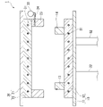
- FIG. 1 is a partially cutaway front view of a press.
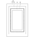
- FIG. 2 is a plan view showing the lower plate portion of the press.
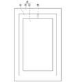
- FIG. 3 is a plan view (seen from below) showing the upper plate portion of the press.
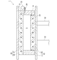
- FIG. 4 is a partially cutaway front view of the press.
- FIG. 5 is a partially cutaway front view of the press.
- FIG. 6 is a partially cutaway front view of the press.
- FIG. 7 shows a portable mold.
- FIG. 8 shows a portable mold.
- FIG. 9 shows a portable mold.
- FIG. 10 is a partially cutaway front view showing a state in which the charged portable mold is pressed by a press.
- FIG. 11 is a drawing for explaining manufacturing steps included in the manufacturing method according to the embodiment.
- FIG. 12A and 12B are diagrams for explaining manufacturing steps included in the manufacturing method according to the embodiment.
- 13A and 13B are diagrams for explaining manufacturing steps included in the manufacturing method according to the embodiment.
- 14A and 14B are diagrams for explaining manufacturing steps included in the manufacturing method according to the embodiment.
- FIG. 15 is a drawing showing the relationship between the height of the workbench, the height of the loading platform of the cart, and the height of the upper surface of the lower heating platen of the press machine.
- Molding System One embodiment of the present invention relates to a molding system for producing compression molded articles (hereinafter also referred to simply as "molded articles") from thermoset resin materials.
- a molding system according to an embodiment includes a press and at least one portable mold.
- FIG. 1 shows an example of a press machine that can constitute a molding system according to an embodiment.
- the press machine 1 includes a lower plate portion 10, an upper plate portion 20 disposed above the lower plate portion 10 so as to face the lower plate portion 10, and the lower plate portion 10 and the upper plate portion 20.
- a pressurizing mechanism (only the cylinder 32 of the pressurizing mechanism is shown in FIG. 1) is provided for moving them in a direction to bring them closer together.
- the lower plate portion 10 is composed of a horizontally arranged lower substrate 11 and a lower heating platen 12 attached to the upper surface side of the lower substrate 11 .
- the upper plate portion 20 is composed of a horizontally arranged upper substrate 21 and an upper heating plate 22 attached to the lower surface side of the upper substrate 21 .
- FIG. 1 illustration of a frame for fixing the upper plate portion 20 and the like is omitted.
- the pressurizing mechanism is preferably hydraulic because the pressure can be easily controlled.
- the cylinder 32 of the pressure mechanism may be arranged to act on the upper plate portion 20 instead of the lower plate portion 10 .
- a heater 31 is built in each of the lower heating plate 12 and the upper heating plate 22 . Examples of heater 31 include, but are not limited to, steam heaters, oil heaters, electric heaters, and electromagnetic induction heaters.
- An annular lower wall member 13 is fixed to the upper surface of the lower heating platen 12 .
- the lower wall member 13 has a structure in which four vertical walls perpendicular to the upper surface of the lower heating plate 12 are connected to form a rectangular ring. It is arranged slightly inside the peripheral surface of the board 12 .
- the lower heating plate 12 and the lower wall member 13 may be seamlessly integrated.
- the lower wall member 13 is provided with a groove extending around its outer peripheral surface, and a vacuum sealing ring 14 is fitted in the groove.
- An annular upper wall member 23 is fixed to the lower surface of the upper heating plate 22 .
- the upper wall member 23 has a structure in which four vertical walls perpendicular to the lower surface of the upper heating plate 22 are connected to form a rectangular ring. and are arranged along the peripheral surface of the upper heating plate 22 .
- the upper heating plate 22 and the upper wall member 23 may be seamlessly integrated.
- the upper wall member 23 is provided with an exhaust hole 24 passing through one of the vertical walls.
- the exhaust hole 24 is connected to a vacuum pump 33 .
- the lower wall member 13 may be omitted and the lower heating platen 12 and the upper wall member 23 may be fitted together via the vacuum sealing ring 14 .
- the lower plate portion 10 and the upper plate portion 20 are brought close to each other, a closed space S surrounded by the lower heating plate 12, the upper heating plate 22 and the upper wall member 23 is formed.
- a lower wall member 13 and an upper wall member 23, which are fitted together via a vacuum sealing ring, are fixed to the upper surface of the lower substrate 11 and the lower surface of the upper substrate 21, respectively.
- the upper wall member 23 is arranged so as to surround the upper heating plate 22 .
- a closed space S surrounded by the lower substrate 11, the lower wall member 13, the upper substrate 21 and the upper wall member 23 is formed.
- FIG. 7 shows an example of a portable mold that constitutes the molding system according to the embodiment.
- the portable mold 2 consists of a bottom plate 40 , a top plate 50 and three intermediate plates 60 .
- the planar shape of each plate is, for example, a rectangle. Handles can be attached to the sides of any plate if desired. All plates have the same contour shape and dimensions in plan view and can be superimposed on each other.
- the lowermost plate 40 and the intermediate plate 60 directly above it are stacked.
- one and the other of the plates that are adjacent when stacked in the correct order are provided with an alignment protrusion and an alignment recess, respectively, so that the two plates only fit together when they are stacked such that they are exactly on top of each other. You may do so.
- Each plate has two pin holes. After stacking the plates, two pins 3 are inserted into the pin holes 53 of the uppermost plate 50 as shown in FIG. , through the pin holes 63 of the intermediate plate 60 and into the pin holes 43 of the bottom plate 40 .
- the number of intermediate plates that the portable mold can have is not limited to three, and may be two or less or three or more.
- the portable mold can be configured with only the bottom plate and the top plate without using the intermediate plate.
- Both the bottom surface 40b of the bottom plate 40 and the top surface 50a of the top plate 50 are entirely flat.
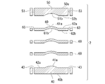
- the upper surface 40a of the lowermost plate 40, the lower surface 50b of the uppermost plate 50, the upper surface 60a and the lower surface 60b of each intermediate plate 60, respectively, have first regions 41a, 51b, 61a, 61b approximately in the center of each surface, and , has second regions 42a, 52b, 62a, 62b around the first region.
- the first area of each face is the area that will become the inner surface of the mold cavity when the plates are stacked. Accordingly, the first region 41a of the upper surface of the bottom plate and the first region 61a of the upper surface of each intermediate plate have a shape complementary to one surface of the molded article to be manufactured, and the first region of the lower surface of the top plate has a shape complementary to that of one surface. 51b and the first region 61b of the lower surface of each intermediate plate have a shape complementary to the other surface of the molded article to be produced.
- a second region of each face is flat.
- a second region 42a of the top surface of the bottom plate is parallel to the bottom surface 40b of the bottom plate, and a second region 52b of the bottom surface of the top plate is parallel to the top surface 50a of the top plate.
- the second region 62a on the upper surface and the second region 62b on the lower surface of each intermediate plate 60 are parallel to each other.
- both pin holes are formed through a second region that the plate has on its top and/or bottom surface.
- the portable mold according to the preferred embodiment multiple molding cavities are formed between any adjacent plates when all the plates are stacked.
- the portable mold 2 shown in FIG. 9 has nine first regions on the top surface of the bottom plate 40, the top and bottom surfaces of each of the two intermediate plates 60, and the bottom surface of the top plate 50. ing. When these plates are stacked, between the bottom plate 40 and the lower intermediate plate 60, between the two intermediate plates 60, and between the upper intermediate plate 60 and the top plate 50, 9 Individual mold cavities are formed. Therefore, if this portable mold is used, 27 (9 ⁇ 3) pieces of compression-molded products P can be obtained by one-time molding.
- At least part of the plate that constitutes the portable mold may be split into two or more.
- at least some of the plates may have an insert structure and consist of a matrix and a nest.
- the portable mold may include a set core in addition to the bottom plate, top plate and middle plate. Placement cores are used when manufacturing moldings with undercuts.
- a portable mold 2 charged with a thermosetting resin material M is placed in a closed space S formed in the press machine 1 described above, and pressed by a lower plate portion 10 and an upper plate portion 20. Show where you are pressing. Since the lower heating plate 12 and the upper heating plate 22 are exposed in the lower plate portion 10 and the upper plate portion 20 respectively, the portable mold 2 is in direct contact with the lower heating plate 12 and the upper heating plate 22 . Since the lower surface (lower surface 40b of the lowermost plate) and the upper surface (upper surface 50a of the uppermost plate) are flat, the contact with the respective lower heating plate 12 and upper heating plate 22 is planar. On the other hand, the sides of the portable mold 2 are in contact with neither the lower wall member 13 nor the upper wall member 23 . In other words, the sides of the portable mold 2 are surrounded by spaces.
- the resin material M is melted in the molding cavity of the portable mold 2, and part of the melted resin flows through the gap between the plates forming the molding cavity and flows into the portable mold 2. Acts as a trap to prevent resin material M from entering the vacuum line if it leaks out of the .
- the space between the side of the portable mold 2 and the lower wall member 13 and the upper wall member 23 is also advantageous in that the operation of placing the portable mold 2 inside these side wall members is facilitated. is.
- Examples of materials for portable molds include carbon steel and alloy steel (steel to which chromium, molybdenum, tungsten, vanadium, etc. are added) that have traditionally been used as steel materials for plastic molding.
- each plate that constitutes the portable mold 2 normally does not have a heat source inside.
- a heat source for heating the resin material M is a heater 31 built in each of the lower heating plate 12 and the upper heating plate 22 . Therefore, it is desirable to facilitate heat transfer from the lower heating plate 12 and the upper heating plate 22 to the resin material M through the portable mold 2 in order to cure the resin material M in a shorter time.
- the material of the portable mold 2 may be an aluminum alloy or a copper alloy such as beryllium copper, which has higher thermal conductivity than steel. These alloys have a high thermal conductivity of 100 W/(m ⁇ K) or more at 20°C. Aluminum alloys are particularly preferred due to their high thermal conductivity and light weight. The specific gravity at 20° C. is around 7.9 for steel materials and exceeds 8 for beryllium copper, whereas aluminum alloys are usually 2.7 to 2.8.
- Examples of aluminum alloys include 7000 series aluminum alloys (Al-Zn-Mg alloys), which are said to have the highest strength among aluminum alloys, and 2000 series aluminum alloys (Al-Cu alloys), which have strength comparable to steel materials. ), including but not limited to.
- the thermal conductivity of aluminum alloys varies depending on the refining, but the thermal conductivity at 20°C is 130 to 190 W/(m K) for A2017 (duralumin), 150 W/(m K) for A7003, and 150 W/(m K) for A7075 (exceeding Super duralumin) is said to be 130 W/(m ⁇ K).
- the weight of the portable mold 2 can be, for example, 2 kg or more and 30 kg or less. A weight within this range is convenient for transporting the portable mold. However, the weight of the portable mold is not limited within this range. If a power-equipped transport mechanism is introduced, a portable mold weighing nearly 200 kg can be used.
- the molding system according to the embodiment may further include a workbench as a component other than the press and the portable mold.
- the workbench can be used not only for charging the portable mold 2 with the resin material M, but also for removing the compression-molded product P from the portable mold 2 . These operations can be performed using the same workbench or different workbench.
- a molding system according to embodiments may further include a carriage for transporting the portable mold 2 . For preferred aspects of the workbench and carriage, see 2. below. section.
- a molding system may include at least one of each component.
- the molding system includes at least two portable dies per press.
- the at least two transportable molds may include a plurality of transportable molds with the same cavity shape, or may include transportable molds with mutually different cavity shapes.
- the number of transportable molds per press machine is described in 3. below. In the continuous production described in the section, it is preferable that the number is more than the required number so that the press machine does not have a waiting time due to shortage of portable dies. If each plate of the portable mold has an insert structure and the shape of the cavity can be changed by exchanging the inserts, it is possible to manufacture molded products of various shapes using a single portable mold. , the number of transportable dies required can be reduced.
- Another embodiment of the invention relates to a method of making compression molded articles.
- the above 1. The molding system described in Section 1 above can preferably be used.
- a manufacturing method according to an embodiment typically includes the following steps.
- First step outside the press, a portable die is charged with a thermosetting resin material (Fig. 11).
- Second step The portable mold charged in the first step is sandwiched between the lower heating platen and the upper heating platen preheated to the molding temperature of the press machine, and the surroundings are surrounded by a decompressible space (Fig. 12). ).
- Third step While reducing the pressure in the depressurizable space, the portable mold is further pressurized between the lower and upper heating plates maintained at the molding temperature to harden the resin material in the portable mold. .
- Fourth step Take out the portable mold from the press (Fig. 13).
- Fifth step Take out the compression-molded product from the portable mold (Fig. 14).
- thermosetting resin material (resin composition) M outside the press machine 1 .
- the resin material M may be placed in the portable mold 2 while being superimposed on a core material such as a honeycomb core or foam core.
- thermosetting resins that are blended as base resins in resin materials include epoxy resins, unsaturated polyester resins, acrylic resins, vinyl ester resins, phenol resins, and benzoxazine resins.
- the resin material may optionally contain various additives such as reactive diluents, release agents, defoaming agents, UV absorbers, and fillers.
- the resin material may be prepreg.
- a prepreg is a fiber reinforcement impregnated with a thermosetting matrix resin.
- the fibrous reinforcement consists of at least one fiber, each of which may be inorganic, organic or metallic.
- inorganic fibers include carbon fibers, silicon carbide fibers, alumina fibers, tungsten carbide fibers, boron fibers, and glass fibers.
- Inorganic fibers may be coated with metal.
- Organic fibers include aramid fibers, polyimide fibers, ultra-high molecular weight polyethylene fibers, nylon fibers, polyester fibers and the like.
- metal fibers include stainless fibers and iron fibers.
- a prepreg obtained by impregnating a fiber reinforcing material made of carbon fibers with a thermosetting resin composition, especially an epoxy resin composition, is one of the most preferable resin materials because it gives a lightweight and high-strength FRP by curing.
- prepreg examples include UD prepreg and woven prepreg.
- the basis weight of the fiber reinforcing material in these prepregs is preferably 50-800 g/m 2 , more preferably 75-300 g/m 2 .
- Textile prepregs include, for example, plain weave, twill weave, satin weave, triaxial weave, and the like.
- Other prepregs include SMC (sheet molding compound).
- a single layer of prepreg may be used, or a plurality of prepregs may be used by stacking them.
- a plurality of prepregs are stacked and used, only prepregs of the same kind may be laminated, or prepregs of different kinds may be laminated.
- UD prepregs are stacked and used, cross-ply lamination or angle-ply lamination is preferred.
- the woven fabric prepreg may be used only for the outermost layer so that a molded product having a surface through which the highly designed fabric can be seen through can be obtained.
- SMC can also be used overlaid with UD prepreg or woven prepreg.
- thermal grease may be applied to the contact surfaces between the adjacent plates in order to reduce the contact thermal resistance between the plates. Reduce the contact thermal resistance between the portable mold 2 and these heating plates when the portable mold 2 is sandwiched between the lower heating plate 12 and the upper heating plate 22 in the second step and the fourth step later.
- the lower surface 40b of the lowermost plate and the upper surface 50a of the uppermost plate of the portable mold 2 may be coated with thermal conductive grease.
- the work of charging the portable mold 2 with the resin material M is performed in a room at a temperature of 17 to 28° C. using a workbench with a top plate on which the plate of the portable mold can be stably placed. can be done.
- the temperature of the portable mold during charging can be the same as room temperature.
- a portable mold heated for the purpose of drying after washing may be charged before the temperature drops to room temperature, but wrinkles may occur during handling when the resin material is UD prepreg or textile prepreg.
- a low temperature of the portable mold during charging for example below 40° C. or even below 28° C., is necessary when charging takes a relatively long time due to the complexity of the shape of the part to be produced. It is advantageous to This is because there is no problem that the temperature of the resin material rises during charging and the tackiness increases, making handling difficult.
- the low temperature of the portable mold during charging is also advantageous when the duration of the first step is long because the portable mold has a large number of molding cavities. This is because the molded product obtained from the resin material placed in the portable mold immediately after the start of the first process and the molded product obtained from the resin material placed in the portable mold immediately before the end of the first process This is because there is substantially no difference in physical properties between them due to the difference in thermal history received in the first step.
- the portable mold 2 charged with the resin material M is preferably preheated prior to the second step. By preheating, the time for the subsequent fourth step can be shortened. Preheating is performed so that the viscosity of the resin material does not significantly decrease.
- the temperature of the portable mold after preheating is preferably 40° C. or higher and 80° C. or lower, and more preferably 60° C. or higher and 80° C. or lower. If the temperature of the portable mold is 80° C. or less, the mold can be touched with a gloved hand, so there is no problem in transportation.
- the portable mold charged on the workbench is transported to the heater as necessary, preheated, and then transported to the press for the second process.
- the transportation may be carried out manually or by using a trolley.
- the weight of the portable mold is large or when many portable molds are transported at once, it is preferable to use a trolley.
- the height of the platform of the trolley is preferably the same as the height of the workbench.
- the portable mold can be transferred from the workbench to the carriage simply by sliding it horizontally. Furthermore, if a roller conveyor is provided on the loading platform of the carriage, the transfer becomes easier.
- the height of the platform of the truck means the height of the lower surface of the portable mold (lower surface of the bottom plate) when the portable mold is appropriately placed on the platform.
- the height of the workbench refers to the height of the upper surface of the top surface of the workbench. Even if the height of the platform of the carriage and the height of the workbench are slightly different, if the difference is smaller than the thickness of the bottom plate of the portable mold, both heights can be regarded as the same.
- Second Step In the second step, as shown in FIG. 12, the portable mold 2 charged in the first step is placed between the lower heating platen 12 and the upper heating platen 22 of the press machine 1 preheated to the molding temperature. and surrounded by a closed space S.
- the reason why the lower heating platen 12 and the upper heating platen 22 of the press machine 1 are preliminarily heated to the molding temperature is to shorten the time required for the subsequent fourth step.
- the molding temperature can be 110° C. to 130° C., 130° C. to 135° C., 135° C. to 145° C., 145° C. to 150° C., 150° C. to 180° C., and the like.
- the lower plate portion 10 and the upper plate portion 20 are separated until the upper surface of the portable mold (the upper surface 50 a of the top plate) contacts the upper heating platen 22 . bring closer.
- the lower wall member 13 and the upper wall member 23, which are annular, are fitted together via the vacuum sealing ring 14, and a closed space S that can be decompressed is formed around the portable mold 2.
- the surface pressure that the portable mold 2 receives is preferably about 1 to 15 mPa.
- Third step In the third step, the closed space S formed around the portable mold 2 in the second step is decompressed, and the pressure is reduced between the lower heating platen 12 and the upper heating platen 22 maintained at the molding temperature.
- the transport mold is further pressurized to harden the resin material M in the transport mold 2 .
- the closed space S is decompressed by operating the vacuum pump 33 so that the pressure after decompression is preferably 0.1 Pa or less, more preferably 0.01 Pa or less.
- the pressurization of the portable mold 2 is performed so that the surface pressure is preferably in the range of 1 to 15 MPa.
- the pressurization may be started at the same time as the pressure reduction of the closed space S is started, or may be after.
- pressurization may be started before or after the closed space S is sufficiently depressurized.
- the purpose of reducing the pressure in the closed space S is to deaerate the resin material M and obtain a void-free compression-molded product P. Therefore, it is desirable that the closed space S is sufficiently decompressed before the resin material M gels. This is because a resin material whose viscosity has increased significantly due to gelation is difficult to deaerate.
- the time for the third step is set to a time sufficient for the resin material M to harden to the required degree.
- the curing characteristics of the resin material, the size of the compression-molded product to be manufactured, the molding temperature, the material of the portable mold, the number of plates included in the portable mold, etc., should be taken into account, Can be determined by error.
- the portable mold 2 is removed from the press machine 1 .
- the transportable mold 2 that has been taken out is transported onto the workbench.
- the workbench may be the same as that used in the first step, or it may be different.
- Transportation may be performed manually or by using a trolley.
- the lower wall member 13 of the press machine 1 since the upper end of the lower wall member 13 of the press machine 1 is higher than the upper surface of the lower heating platen 12, when the portable mold 2 is transferred from the lower heating platen 12 to the carriage, the lower wall member It is necessary to lift above the top of 13.
- the mold 2 can be easily transferred from the lower heating platen 12 to the carriage.
- the portable mold can be transferred from the lower heating plate to the truck simply by horizontally sliding it. If the height of the loading platform of the truck is the same as that of the workbench, it is only necessary to horizontally slide the portable mold from the truck to the workbench.
- the compression-molded product P is taken out from the portable mold 2 . It is preferable to forcibly cool the compression-molded product P immediately after taking it out of the portable mold 2 while taking care not to deform it.
- Portable molds are also preferably forced to cool immediately after removal of the compression molded article for use in the next molding cycle. The forced cooling of the portable mold 2 can also be performed before the compression-molded product P is taken out.
- a plurality of charged portable molds are arranged side by side between the lower heating platen and the upper heating platen of one press machine, and in the third step, the plurality of portable molds may be pressurized at the same time.
- a plurality of charged portable molds are vertically stacked between the lower heating platen and the upper heating platen of one press machine, and in the third step, the plurality of of portable molds may be pressurized at the same time.
- the portable mold can be easily remounted by simply horizontally sliding it between the lower heating plate 12 and the carriage 72 and between the carriage 72 and the workbench 71.
- the height of the upper surface of the lower heating plate should be adjusted to the height of the workbench.
- a lift truck to transport the portable mold.
- different portable molds with different cavity shapes can be used for the Nth molding cycle and the (N+1)th molding cycle.
- the second step of the (N+1)th molding cycle can be performed while the lower substrate and the upper substrate of the press machine are maintained at the molding temperature without being cooled. Therefore, it is possible to produce various molded products in small quantities with high efficiency.
- Embodiments of the invention include the following.
- a molding system for manufacturing a compression-molded product from a thermosetting resin material comprising a press and one or more portable molds, the press having a lower a lower plate portion including a heating plate; an upper plate portion including an upper heating plate; and at least one annular side wall member each fixed to the lower plate portion or the upper plate portion, and a closed space surrounded by the lower plate portion, the upper plate portion, and the at least one side wall member, which can be depressurized, is formed when the plate portion and the upper plate portion are brought closer to each other;
- a molding system which is a pressing machine in which at least one portable mold is arranged in a space so that pressure can be applied between the lower plate portion and the upper plate portion.
- the closed space is defined by an annular lower wall member fixed to the lower plate portion and an annular upper wall member fixed to the upper plate portion, or an annular lower wall member fixed to the lower plate portion. and the upper heating plate, or alternatively, the upper wall member fixed to the upper plate portion and the lower heating plate may be formed by fitting together via a vacuum sealing ring.
- the at least one sidewall member of the press comprises a sidewall member secured to the top plate portion.
- the at least one side wall member of the press includes a side wall member provided with an exhaust port, the exhaust port being connected to a vacuum pump.
- the portable mold is composed of a plurality of plates including a bottom plate having a flat bottom surface and a top plate having a flat top surface, and the bottom plate and the top plate are respectively located at the bottom. and when the plurality of plates are stacked on top, the bottom surface of the bottom plate and the top surface of the top plate are parallel to each other, and there is at least one molding cavity between any adjacent plates A molding system according to any of embodiments 1-3, formed.
- Embodiment 5 The molding system according to Embodiment 4, wherein said plurality of plates includes said bottom plate and said top plate plus at least one intermediate plate.
- Embodiment 6 Any one of Embodiments 1 to 5, wherein the material of the portable mold is an aluminum alloy that may be 2000 series or 7000 series, or may be A2017, A7003 or A7075. molding system.
- Embodiment 7 The molding system according to any one of Embodiments 1 to 6, wherein the weight of the portable mold is 2 kg or more and 30 kg or less.
- the at least one portable mold can be arranged in the closed space so as not to contact any of the at least one side wall member. molding system.
- Each of the lower heating platen and the upper heating platen is in direct and surface contact with at least one of the portable molds pressurized by the lower plate portion and the upper plate portion.
- Embodiment 12 The molding system according to any one of Embodiments 1 to 11, further comprising a workbench used for taking out the compression-molded product from the portable mold.
- Embodiment 13 The molding system according to any one of Embodiments 1 to 12, further comprising a carriage for transporting the portable mold.
- Embodiment 14 A molding system according to Embodiment 13, wherein the carriage is a lifting carriage.
- the first workbench includes a first workbench used for charging the portable mold with the resin material, and a carriage for transporting the portable mold. 11.
- the height of the carriage and the height of the carriage bed are the same.
- a second workbench used for taking out the compression-molded product from the portable mold is included, and the height of the first workbench and the height of the second workbench are the same.
- a molding system according to Embodiment 15. [Embodiment 17] The height of the upper surface of the lower heating plate of the press machine is fixed at the same height as the loading platform of the carriage, and the portable mold is horizontally slid to lift the lower heating plate. 17.
- Embodiment 18 A method for manufacturing a compression-molded article, wherein the molding system according to any one of Embodiments 1 to 17 is used to manufacture a compression-molded article from a thermosetting resin material.
- Embodiment 19 A first step of charging a portable mold with a thermosetting resin material outside the press; A second step of sandwiching between a lower heating plate and an upper heating plate preheated to a molding temperature and surrounding the surroundings with a pressure-reducing space; depressurizing the pressure-reducing space and the lower heat maintained at the molding temperature A third step of further pressurizing the portable mold between the platen and the upper heating plate to harden the resin material in the portable mold; a fourth step of removing the portable mold from the press machine.
- Embodiment 20 A manufacturing method according to Embodiment 19, wherein the first step is performed in a room at a temperature of 17 to 28°C.
- Embodiment 21 The manufacturing method according to Embodiment 20, wherein the temperature of the portable mold in the first step is 40°C or less and may be the same as the temperature in the chamber.
- the portable mold is composed of a plurality of plates including a bottom plate having a flat bottom surface and a top plate having a flat top surface, and the bottom plate and the top plate are respectively located at the bottom.
- Embodiment 23 The method of Embodiment 22, wherein said plurality of plates comprises said bottom plate and said top plate plus at least one intermediate plate.
- Embodiment 24 The manufacturing method according to Embodiment 22 or 23, wherein the material of the portable mold is an aluminum alloy that may be 2000 series or 7000 series, or may be A2017, A7003 or A7075. .
- Embodiment 25 The manufacturing method according to any one of Embodiments 22 to 24, wherein the weight of the portable mold is 2 kg or more and 30 kg or less.
- Embodiment 26 The manufacturing method according to any one of Embodiments 22 to 25, wherein in the first step, heat-conducting grease is applied to contact surfaces between adjacent plates.
- Embodiment 27 The manufacturing method according to any one of Embodiments 22 to 26, wherein the bottom surface of the bottom plate and the top surface of the top plate are coated with heat conductive grease before the second step.
- each of the lower heating platen and the upper heating platen is directly connected to at least one of the portable molds pressurized between the lower heating platen and the upper heating platen. and in surface contact.
- the depressurizable space is depressurized to 0.1 Pa or less, preferably 0.01 Pa or less, and the portable mold is pressurized with a surface pressure within the range of 1 to 15 MPa. 29.
- the manufacturing method according to any one of embodiments 19-28.
- the press includes a lower plate portion including the lower heating plate and an upper plate portion including the upper heating plate, each of which is fixed to the lower plate portion or the upper plate portion and has an annular shape. and at least one side wall member, and is decompressible surrounded by the lower plate portion, the upper plate portion, and the at least one side wall member when the lower plate portion and the upper plate portion are brought close to each other.
- N is an integer of 1 or more
- the 32 is any one of embodiments 19 to 31, wherein the molding cycle is repeated so as to perform the second step of the (N+1)th molding cycle while maintaining the lower heating platen and the upper heating platen at the molding temperature without cooling.
- the manufacturing method which concerns.
- Embodiment 33 The manufacturing method according to Embodiment 32, wherein the portable mold used in the Nth molding cycle is different from the portable mold used in the (N+1)th molding cycle.
- Embodiment 34 According to embodiment 33, wherein the portable mold used in the Nth molding cycle and the portable mold used in the (N+1)th molding cycle have molding cavities of different shapes. The manufacturing method which concerns.
- Embodiment 35 The manufacturing method according to any one of Embodiments 19 to 34, wherein the resin material is prepreg.
Landscapes
- Engineering & Computer Science (AREA)
- Mechanical Engineering (AREA)
- Chemical & Material Sciences (AREA)
- Composite Materials (AREA)
- Casting Or Compression Moulding Of Plastics Or The Like (AREA)
- Moulds For Moulding Plastics Or The Like (AREA)
Abstract
熱硬化性の樹脂材料から圧縮成形品を製造するための成形システムであって、前記成形システムはプレス機と少なくともひとつの可搬金型とからなり、前記プレス機は、下熱盤を含む下板部と、上熱盤を含む上板部と、それぞれが前記下板部又は前記上板部に固定され、かつ環状である少なくともひとつの側壁部材とを有し、前記下板部と前記上板部を互いに近付けたときに、前記下板部、前記上板部及び前記少なくともひとつの側壁部材で囲まれた減圧可能な閉空間が形成されるように、かつ、前記閉空間内に前記可搬金型を配置して前記下板部と前記上板部とで加圧できるようにしたプレス機である、成形システムが提供される。
Description
本発明は、熱硬化性の樹脂材料から圧縮成形品を製造するための成形システム及び圧縮成形品の製造方法に関する。
本願は、2021年3月31日に日本に出願された特願2021-059523号に基づき優先権を主張し、その内容をここに援用する。
本願は、2021年3月31日に日本に出願された特願2021-059523号に基づき優先権を主張し、その内容をここに援用する。
繊維強化プラスチック(FRP)は、軽量で優れた機械特性を有するため、スポーツ、レジャー用途から、自動車や航空機等の産業用途まで、幅広く用いられている。
繊維強化プラスチックからなる成形品は、プリプレグを出発材料に用いて、圧縮成形法により製造することができる(特許文献1)。
特許文献1に記載された方法では、プリプレグでチャージする前に金型が、プリプレグを十分に硬化させ得る温度まで加熱されている。
樹脂組成物からなる成形板を一度に多数製造するための多段プレス機が知られている(特許文献2)。
本発明の主たる目的は、熱硬化性の樹脂材料を用いてボイドの少ない圧縮成形品を効率よく生産するための成形システム及び製造方法を提供することにある。
本発明の一態様によれば、熱硬化性の樹脂材料から圧縮成形品を製造するための成形システムが提供される。前記成形システムはプレス機と少なくともひとつの可搬金型とからなる。前記プレス機は、下熱盤を含む下板部と、上熱盤を含む上板部と、それぞれが前記下板部又は前記上板部のいずれかに固定され、かつ環状である少なくともひとつの側壁部材とを有し、前記下板部と前記上板部を互いに近付けたときに、前記下板部、前記上板部及び前記少なくともひとつの側壁部材で囲まれた減圧可能な閉空間が形成されるように、かつ、前記閉空間内に前記可搬金型を配置して前記下板部と前記上板部とで加圧できるようにしたプレス機である。
本発明の他の一態様によれば、プレス機の外部にて、可搬金型を熱硬化性の樹脂材料でチャージする第一工程;第一工程でチャージされた前記可搬金型を、プレス機の予め成形温度に加熱された下熱盤と上熱盤とで挟むとともに、その周囲を減圧可能な空間で取り囲む第二工程;前記減圧可能な空間を減圧するとともに、前記成形温度に保たれた前記下熱盤と前記上熱盤の間で前記可搬金型を更に加圧し、前記可搬金型内の前記樹脂材料を硬化させる第三工程;前記可搬金型を前記プレス機から取り出す第四工程;前記可搬金型から圧縮成形品を取り出す第五工程;を含む、圧縮成形品の製造方法が提供される。
本発明の好ましい実施形態によれば、熱硬化性の樹脂材料を用いてボイドの少ない圧縮成形品を効率よく生産するための成形システム及び製造方法が提供される。
以下では本発明の実施形態を説明する。ただし、本発明は後述する実施形態に限定されず、本発明の要旨を逸脱しない限り種々の変形が可能である。
1.成形システム
本発明の一実施形態は、熱硬化性の樹脂材料から圧縮成形品(以下では単に「成形品」とも呼ぶ)を製造するための成形システムに関する。
実施形態に係る成形システムは、プレス機と少なくともひとつの可搬金型とからなる。
本発明の一実施形態は、熱硬化性の樹脂材料から圧縮成形品(以下では単に「成形品」とも呼ぶ)を製造するための成形システムに関する。
実施形態に係る成形システムは、プレス機と少なくともひとつの可搬金型とからなる。
1.1.プレス機
図1に、実施形態に係る成形システムを構成し得るプレス機の一例を示す。 図1を参照すると、プレス機1は、下板部10と、下板部10の上方において下板部10と対向配置された上板部20と、下板部10と上板部20とを互いに近づける方向に動かす加圧機構(図1では加圧機構のシリンダー32のみ図示)を備えている。
下板部10は、水平に配置された下基板11と、下基板11の上面側に取り付けられた下熱盤12とからなる。
上板部20は、水平に配置された上基板21と、上基板21の下面側に取り付けられた上熱盤22とからなる。
図1において、上板部20等を固定するフレームの図示は省略している。
図1に、実施形態に係る成形システムを構成し得るプレス機の一例を示す。 図1を参照すると、プレス機1は、下板部10と、下板部10の上方において下板部10と対向配置された上板部20と、下板部10と上板部20とを互いに近づける方向に動かす加圧機構(図1では加圧機構のシリンダー32のみ図示)を備えている。
下板部10は、水平に配置された下基板11と、下基板11の上面側に取り付けられた下熱盤12とからなる。
上板部20は、水平に配置された上基板21と、上基板21の下面側に取り付けられた上熱盤22とからなる。
図1において、上板部20等を固定するフレームの図示は省略している。
加圧機構は、圧力をコントロールしやすいことから、液圧式であることが好ましい。加圧機構のシリンダー32は、下板部10ではなく、上板部20に作用するように配置されてもよい。
下熱盤12と上熱盤22にはそれぞれヒーター31が内蔵されている。
ヒーター31の例には蒸気ヒーター、オイルヒーター、電熱ヒーター及び電磁誘導ヒーターが含まれるが、これらに限定されない。
下熱盤12と上熱盤22にはそれぞれヒーター31が内蔵されている。
ヒーター31の例には蒸気ヒーター、オイルヒーター、電熱ヒーター及び電磁誘導ヒーターが含まれるが、これらに限定されない。
下熱盤12の上面には、環状の下側壁部材13が固定されている。図2に平面図を示すように、下側壁部材13は、それぞれ下熱盤12の上面に対し垂直な4つの垂直壁が、矩形の環を成すようにつながった構造をしており、下熱盤12の周面よりやや内側に配置されている。下熱盤12と下側壁部材13は継目なしに一体化していてもよい。
下側壁部材13には外周面を一周する溝が設けられ、その溝には真空シーリング・リング14が嵌め込まれている。
下側壁部材13には外周面を一周する溝が設けられ、その溝には真空シーリング・リング14が嵌め込まれている。
上熱盤22の下面には、環状の上側壁部材23が固定されている。図3に平面図(下方から見たところ)を示すように、上側壁部材23は、それぞれ上熱盤22の下面に対し垂直な4つの垂直壁が、矩形の環を成すようにつながった構造をしており、上熱盤22の周面に沿って配置されている。上熱盤22と上側壁部材23は継目なしに一体化していてもよい。
上側壁部材23には、垂直壁のひとつを貫通する排気孔24が設けられている。排気孔24は真空ポンプ33に接続されている。
上側壁部材23には、垂直壁のひとつを貫通する排気孔24が設けられている。排気孔24は真空ポンプ33に接続されている。
加圧機構を作動させて下板部10を上板部20に近付けると、図4に示すように下側壁部材13と上側壁部材23が真空シーリング・リング14を介して篏合し、下熱盤12、下側壁部材13、上熱盤22及び上側壁部材23で囲まれた閉空間Sが形成される。この閉空間は、真空ポンプ33を作動させることにより減圧することができる。
変形例においては、図5に示すように、下側壁部材13を省略し、下熱盤12と上側壁部材23が真空シーリング・リング14を介して篏合するように構成してもよい。この場合は、下板部10と上板部20を近付けたとき、下熱盤12、上熱盤22及び上側壁部材23で囲まれた閉空間Sが形成される。
他の変形例においては、図6に示すように、真空シーリング・リングを介して互いに篏合する下側壁部材13と上側壁部材23を、下基板11の上面と上基板21の下面にそれぞれ固定してもよい。下側壁部材13は下熱盤12を取り囲むように配置し、また、上側壁部材23は上熱盤22を取り囲むように配置する。この場合は、下板部10と上板部20を近付けたとき、下基板11、下側壁部材13、上基板21及び上側壁部材23で囲まれた閉空間Sが形成される。
1.2.可搬金型
実施形態に係る成形システムを構成する可搬金型の一例を図7に示す。
図2を参照すると、可搬金型2は、最下プレート40と最上プレート50と3枚の中間プレート60からなる。各プレートの平面形状は、例えば矩形である。 必要に応じて、どのプレートにも側部に取手を取り付けることができる。
全てのプレートは平面視における外郭形状と外郭寸法が同じであり、互いにぴったり重ね合わせることができる。
実施形態に係る成形システムを構成する可搬金型の一例を図7に示す。
図2を参照すると、可搬金型2は、最下プレート40と最上プレート50と3枚の中間プレート60からなる。各プレートの平面形状は、例えば矩形である。 必要に応じて、どのプレートにも側部に取手を取り付けることができる。
全てのプレートは平面視における外郭形状と外郭寸法が同じであり、互いにぴったり重ね合わせることができる。
図8に示すように、最下プレート40の上に3枚の中間プレート60と最上プレート50を、この順に、互いにぴったりと重なるように積み重ねたとき、最下プレート40とその直上の中間プレート60との間、隣り合う中間プレート60の間、及び、最上プレート50とその直下の中間プレート60との間に、それぞれ成形キャビティが形成される。
一例では、正しい順序で積み重ねたときに隣り合うプレートの一方と他方に、それぞれアライメント用凸部とアライメント用凹部を設け、2つのプレートがぴったり重なるように積み重ねたときにのみ、これらが篏合するようにしてもよい。
一例では、正しい順序で積み重ねたときに隣り合うプレートの一方と他方に、それぞれアライメント用凸部とアライメント用凹部を設け、2つのプレートがぴったり重なるように積み重ねたときにのみ、これらが篏合するようにしてもよい。
各プレートには2個のピン穴が設けられている。プレートを積み重ねた後、プレート間で方向のズレ(回転ズレ)や位置のズレ(水平ズレ)が発生しないよう、図8に示すように、2本のピン3をそれぞれ最上プレート50のピン穴53から、中間プレート60のピン穴63を通って最下プレート40のピン穴43に入るよう差し込むことができる。
可搬金型が有し得る中間プレートは3枚に限定されるものではなく、2枚以下であってもよいし3枚以上でもよい。一例では、中間プレートを用いないで、最下プレートと最上プレートだけで可搬金型を構成することもできる。
最下プレート40の下面40b及び最上プレート50の上面50aは、いずれも全体が平坦である。
最下プレート40の上面40a、最上プレート50の下面50b、各中間プレート60の上面60a及び下面60bは、それぞれ、各面の略中央に第一領域41a、51b、61a、61bを有し、また、第一領域の周囲に第二領域42a、52b、62a、62bを有する。
最下プレート40の上面40a、最上プレート50の下面50b、各中間プレート60の上面60a及び下面60bは、それぞれ、各面の略中央に第一領域41a、51b、61a、61bを有し、また、第一領域の周囲に第二領域42a、52b、62a、62bを有する。
各面の第一領域は、プレートを積み重ねたときに成形キャビティの内面となる領域である。
従って、最下プレートの上面の第一領域41aと各中間プレートの上面の第一領域61aは、製造する成形品の一方の面と相補的な形状を有し、最上プレートの下面の第一領域51bと各中間プレートの下面の第一領域61bは、製造する成形品の他方の面と相補的な形状を有する。
従って、最下プレートの上面の第一領域41aと各中間プレートの上面の第一領域61aは、製造する成形品の一方の面と相補的な形状を有し、最上プレートの下面の第一領域51bと各中間プレートの下面の第一領域61bは、製造する成形品の他方の面と相補的な形状を有する。
各面の第二領域は平坦である。
最下プレートの上面の第二領域42aは当該最下プレートの下面40bと平行であり、最上プレートの下面の第二領域52bは当該最上プレートの上面50aと平行である。各中間プレート60の上面の第二領域62aと下面の第二領域62bは互いに平行である。
最下プレートの上面の第二領域42aは当該最下プレートの下面40bと平行であり、最上プレートの下面の第二領域52bは当該最上プレートの上面50aと平行である。各中間プレート60の上面の第二領域62aと下面の第二領域62bは互いに平行である。
プレートを積み重ねたとき、隣り合うプレート間では第二領域同士が接触する。従って、全てのプレートを積み重ねたとき、最下プレートの下面40bと最上プレートの上面50aは互いに平行となる。
各プレートにおいて、2個のピン穴はいずれも、当該プレートが上面及び/又は下面に有する第二領域を通過するように形成される。
各プレートにおいて、2個のピン穴はいずれも、当該プレートが上面及び/又は下面に有する第二領域を通過するように形成される。
好適例に係る可搬金型では、全てのプレートを積み重ねたときに、どの隣り合うプレートの間にも複数の成形キャビティが形成される。
例えば、図9に示す可搬金型2は、最下プレート40の上面、2枚の中間プレート60それぞれの上面及び下面、最上プレート50の下面のそれぞれに、9個の第一領域を有している。これらのプレートを積み重ねたとき、最下プレート40と下側の中間プレート60との間、2枚の中間プレート60の間、及び、上側の中間プレート60と最上プレート50との間に、それぞれ9個の成形キャビティが形成される。従って、この可搬金型を用いれば、一度の成形で27(9×3)個の圧縮成形品Pを得ることができる。
例えば、図9に示す可搬金型2は、最下プレート40の上面、2枚の中間プレート60それぞれの上面及び下面、最上プレート50の下面のそれぞれに、9個の第一領域を有している。これらのプレートを積み重ねたとき、最下プレート40と下側の中間プレート60との間、2枚の中間プレート60の間、及び、上側の中間プレート60と最上プレート50との間に、それぞれ9個の成形キャビティが形成される。従って、この可搬金型を用いれば、一度の成形で27(9×3)個の圧縮成形品Pを得ることができる。
一例では、可搬金型を構成するプレートの少なくとも一部が、二つ以上に分割可能であってもよい。言い換えれば、少なくとも一部のプレートはインサート構造を有し、母型と入れ子型とから構成されていてもよい。
他の一例では、可搬金型が、最下プレート、最上プレート及び中間プレートの他に、置き中子を含んでいてもよい。置き中子は、アンダーカットを有する成形品を製造するときに使用される。
他の一例では、可搬金型が、最下プレート、最上プレート及び中間プレートの他に、置き中子を含んでいてもよい。置き中子は、アンダーカットを有する成形品を製造するときに使用される。
図10は、熱硬化性の樹脂材料Mでチャージした可搬金型2を、前述のプレス機1に形成される閉空間S内に配置し、下板部10と上板部20とで加圧しているところを示す。
下板部10と上板部20でそれぞれ下熱盤12と上熱盤22が露出しているので、可搬金型2は下熱盤12及び上熱盤22と直に接している。
可搬金型2の下面(最下プレートの下面40b)と上面(最上プレートの上面50a)は平坦であるため、それぞれの下熱盤12及び上熱盤22との接触は面的である。
一方、可搬金型2の側部は、下側壁部材13にも上側壁部材23にも接していない。言い換えれば、可搬金型2の側部は空間で囲まれている。
下板部10と上板部20でそれぞれ下熱盤12と上熱盤22が露出しているので、可搬金型2は下熱盤12及び上熱盤22と直に接している。
可搬金型2の下面(最下プレートの下面40b)と上面(最上プレートの上面50a)は平坦であるため、それぞれの下熱盤12及び上熱盤22との接触は面的である。
一方、可搬金型2の側部は、下側壁部材13にも上側壁部材23にも接していない。言い換えれば、可搬金型2の側部は空間で囲まれている。
可搬金型2の側部を囲む空間は、可搬金型2の成形キャビティ内で樹脂材料Mが溶融し、その一部が成形キャビティを形成するプレートとプレートの隙間を通して可搬金型2の外部に漏れ出した場合に、樹脂材料Mが真空ラインに入るのを防止するトラップとして作用する。
可搬金型2の側部と下側壁部材13及び上側壁部材23との間に余裕があることは、可搬金型2をこれらの側壁部材の内側に置く操作が容易となる点でも有利である。
可搬金型2の側部と下側壁部材13及び上側壁部材23との間に余裕があることは、可搬金型2をこれらの側壁部材の内側に置く操作が容易となる点でも有利である。
可搬金型の材質としては、プラスチック成形用の鋼材として従来から使用されている炭素鋼や合金鋼(クロム、モリブデン、タングステン、バナジウム等が添加された鋼)が例示される。
可搬金型2を構成する各プレートは、通常、内部に熱源を有さない。樹脂材料Mを加熱するための熱源は、下熱盤12と上熱盤22にそれぞれ内蔵されたヒーター31である。従って、下熱盤12と上熱盤22から可搬金型2を通して樹脂材料Mに熱が伝わり易くすることが、樹脂材料Mをより短時間で硬化させるうえで望ましい。
かかる観点から、好適例では、可搬金型2の材質が、鋼材に比べて高い熱伝導性を有するアルミニウム合金やベリリウム銅のような銅合金であり得る。これらの合金は20℃において100W/(m・K)以上という高い熱伝導率を有する。
アルミニウム合金は熱伝導性が高いうえに軽量であることから特に好ましい。20℃における比重は、鋼材で7.9前後、ベリリウム銅では8を超えるのに対し、アルミニウム合金では通常2.7~2.8である。
かかる観点から、好適例では、可搬金型2の材質が、鋼材に比べて高い熱伝導性を有するアルミニウム合金やベリリウム銅のような銅合金であり得る。これらの合金は20℃において100W/(m・K)以上という高い熱伝導率を有する。
アルミニウム合金は熱伝導性が高いうえに軽量であることから特に好ましい。20℃における比重は、鋼材で7.9前後、ベリリウム銅では8を超えるのに対し、アルミニウム合金では通常2.7~2.8である。
アルミニウム合金の例には、アルミニウム合金の中でも最も強度が高いとされる7000系アルミニウム合金(Al-Zn-Mg系合金)や、鋼材に匹敵する強度を持つ2000系アルミニウム合金(Al-Cu系合金)が含まれるが、これらに限定されるものではない。
アルミニウム合金の熱伝導率は調質により変動するが、20℃での熱伝導率はA2017(ジュラルミン)で130~190W/(m・K)、A7003で150W/(m・K)、A7075(超超ジュラルミン)で130W/(m・K)といわれている。
それに対し、プラスチック成形用の鋼材では、熱伝導性が比較的高いクロムモリブデン鋼でさえ20℃における熱伝導率が約60W/(m・K)であり、炭素鋼の熱伝導率はこれよりも低い。
アルミニウム合金の熱伝導率は調質により変動するが、20℃での熱伝導率はA2017(ジュラルミン)で130~190W/(m・K)、A7003で150W/(m・K)、A7075(超超ジュラルミン)で130W/(m・K)といわれている。
それに対し、プラスチック成形用の鋼材では、熱伝導性が比較的高いクロムモリブデン鋼でさえ20℃における熱伝導率が約60W/(m・K)であり、炭素鋼の熱伝導率はこれよりも低い。
可搬金型2の重量は、例えば2kg以上30kg以下であり得る。重量がこの範囲内であることは、可搬金型を運搬するうえで都合がよい。ただし、可搬金型の重量は、この範囲内に限定されるものではない。動力付きの運搬機構を導入すれば、重量が200kg近い可搬金型を用いることもできる。
1.3.その他
実施形態に係る成形システムの構成要素は、プレス機と可搬金型に限定されない。実施形態に係る成形システムは、プレス機と可搬金型以外の構成要素として、更に、作業台を含んでもよい。
作業台は、可搬金型2を樹脂材料Mでチャージする作業で使用され得る他、可搬金型2から圧縮成形品Pを取り出す作業で使用され得る。これらの作業は、同じ作業台又は異なる作業台を用いて行われ得る。
実施形態に係る成形システムは、更に、可搬金型2を運搬するための台車を含み得る。
作業台と台車の好ましい態様については、後記2.項において説明される。
実施形態に係る成形システムの構成要素は、プレス機と可搬金型に限定されない。実施形態に係る成形システムは、プレス機と可搬金型以外の構成要素として、更に、作業台を含んでもよい。
作業台は、可搬金型2を樹脂材料Mでチャージする作業で使用され得る他、可搬金型2から圧縮成形品Pを取り出す作業で使用され得る。これらの作業は、同じ作業台又は異なる作業台を用いて行われ得る。
実施形態に係る成形システムは、更に、可搬金型2を運搬するための台車を含み得る。
作業台と台車の好ましい態様については、後記2.項において説明される。
実施形態に係る成形システムは、各構成要素を少なくともひとつ含んでいればよい。
好適例において、実施形態に係る成形システムはプレス機1台当たり少なくとも2つの可搬金型を含む。少なくとも2つの可搬金型は、キャビティ形状が同じである可搬金型を複数含んでもよいし、キャビティ形状が互いに異なる可搬金型を含んでもよい。
好適例において、実施形態に係る成形システムはプレス機1台当たり少なくとも2つの可搬金型を含む。少なくとも2つの可搬金型は、キャビティ形状が同じである可搬金型を複数含んでもよいし、キャビティ形状が互いに異なる可搬金型を含んでもよい。
プレス機1台当たりの可搬金型の数は、後記3.項で説明する連続生産において、可搬金型の不足によりプレス機に待機時間が発生しないために必要な数以上であることが好ましい。
可搬金型の各プレートをインサート構造とし、入れ子を交換することによりキャビティ形状を変更できるようにすれば、1つの可搬金型を用いて様々な形状の成形品を製造することができるので、必要な可搬金型の数を削減することができる。
可搬金型の各プレートをインサート構造とし、入れ子を交換することによりキャビティ形状を変更できるようにすれば、1つの可搬金型を用いて様々な形状の成形品を製造することができるので、必要な可搬金型の数を削減することができる。
2.成形品の製造方法
本発明の他の一実施形態は、圧縮成形品の製造方法に関する。
実施形態に係る製造方法では、前記1.項で説明した成形システムを好ましく用い得る。
実施形態に係る製造方法は、典型的には以下の工程を含む。
本発明の他の一実施形態は、圧縮成形品の製造方法に関する。
実施形態に係る製造方法では、前記1.項で説明した成形システムを好ましく用い得る。
実施形態に係る製造方法は、典型的には以下の工程を含む。
第一工程:プレス機の外部にて、可搬金型を熱硬化性の樹脂材料でチャージする(図11)。
第二工程:第一工程でチャージされた可搬金型を、プレス機の予め成形温度に加熱された下熱盤と上熱盤とで挟むとともに、その周囲を減圧可能空間で取り囲む(図12)。
第三工程:前記減圧可能空間を減圧するとともに、前記成形温度に保たれた下熱盤と上熱盤の間で可搬金型を更に加圧し、可搬金型内の樹脂材料を硬化させる。
第四工程:可搬金型を前記プレス機から取り出す(図13)。
第五工程:可搬金型から圧縮成形品を取り出す(図14)。
第二工程:第一工程でチャージされた可搬金型を、プレス機の予め成形温度に加熱された下熱盤と上熱盤とで挟むとともに、その周囲を減圧可能空間で取り囲む(図12)。
第三工程:前記減圧可能空間を減圧するとともに、前記成形温度に保たれた下熱盤と上熱盤の間で可搬金型を更に加圧し、可搬金型内の樹脂材料を硬化させる。
第四工程:可搬金型を前記プレス機から取り出す(図13)。
第五工程:可搬金型から圧縮成形品を取り出す(図14)。
以下、前記1.項で説明した成形システムを用いる場合を例に用いて、各工程の詳細を説明する。
2.1.第一工程
第一工程では、プレス機1の外部にて、可搬金型2を熱硬化性の樹脂材料(樹脂組成物)Mでチャージする。樹脂材料Mは、ハニカムコアや発泡コアのような芯材と重ね合わせて可搬金型2内に置いてもよい。
第一工程では、プレス機1の外部にて、可搬金型2を熱硬化性の樹脂材料(樹脂組成物)Mでチャージする。樹脂材料Mは、ハニカムコアや発泡コアのような芯材と重ね合わせて可搬金型2内に置いてもよい。
樹脂材料にベース樹脂として配合される熱硬化性樹脂としては、例えば、エポキシ樹脂、不飽和ポリエステル樹脂、アクリル樹脂、ビニルエステル樹脂、フェノール樹脂及びベンゾオキサジン樹脂が挙げられる。
樹脂材料には、硬化剤が配合される他、必要に応じて、反応性希釈剤、離型剤、脱泡剤、紫外線吸収剤、充填材などの各種添加剤等が配合され得る。
樹脂材料には、硬化剤が配合される他、必要に応じて、反応性希釈剤、離型剤、脱泡剤、紫外線吸収剤、充填材などの各種添加剤等が配合され得る。
好適例において、樹脂材料はプリプレグであってもよい。プリプレグは、熱硬化性のマトリックス樹脂で繊維補強材を含浸させたものである。
繊維補強材は、それぞれ無機繊維、有機繊維又は金属繊維であってもよい少なくとも1種の繊維からなる。
無機繊維としては、炭素繊維、炭化珪素繊維、アルミナ繊維、タングステンカーバイド繊維、ボロン繊維、ガラス繊維等が挙げられる。無機繊維は金属で被覆されてもよい。有機繊維としては、アラミド繊維、ポリイミド繊維、超高分子量ポリエチレン繊維、ナイロン繊維、ポリエステル繊維等が挙げられる。金属繊維としては、ステンレス繊維、鉄繊維等が挙げられる。
炭素繊維からなる繊維補強材を熱硬化性樹脂組成物、とりわけエポキシ樹脂組成物で含浸させたプリプレグは、硬化によって軽量かつ高強度のFRPを与えることから、最も好ましい樹脂材料のひとつである。
プリプレグの典型例としては、UDプリプレグと織物プリプレグが挙げられる。これらのプリプレグにおける繊維補強材の目付は、50~800g/m2が好ましく、75~300g/m2がより好ましい。
織物プリプレグには、例えば、平織型、綾織型、朱子織型、三軸織型等がある。
その他のプリプレグとして、SMC(シートモールディングコンパウンド)が挙げられる。
織物プリプレグには、例えば、平織型、綾織型、朱子織型、三軸織型等がある。
その他のプリプレグとして、SMC(シートモールディングコンパウンド)が挙げられる。
プリプレグは、単層で使用してもよいし、複数枚を重ねて使用してもよい。複数枚を重ねて使用するときは、同一種類のプリプレグのみを積層してもよいし、異なる種類のプリプレグを積層してもよい。
UDプリプレグ同士を重ねて使用するときは、クロスプライ積層又はアングルプライ積層することが好ましい。
一例では、意匠性の高い織物が透けて見える表面を持つ成形品が得られるように、複数枚のプリプレグを積層するときに、最外層にのみ織物プリプレグを用いてもよい。
SMCを、UDプリプレグ又は織物プリプレグと重ねて使用することもできる。
UDプリプレグ同士を重ねて使用するときは、クロスプライ積層又はアングルプライ積層することが好ましい。
一例では、意匠性の高い織物が透けて見える表面を持つ成形品が得られるように、複数枚のプリプレグを積層するときに、最外層にのみ織物プリプレグを用いてもよい。
SMCを、UDプリプレグ又は織物プリプレグと重ねて使用することもできる。
可搬金型2をチャージするとき、プレート間の接触熱抵抗を下げるために、隣り合うプレート間の接触面に熱伝導グリス(thermal grease)を塗ってもよい。
後の第二工程及び第四工程において下熱盤12と上熱盤22で可搬金型2を挟んだときの、可搬金型2とこれらの熱盤との間の接触熱抵抗を下げるために、可搬金型2の最下プレートの下面40bと最上プレートの上面50aに熱伝導グリスを塗ることもできる。
後の第二工程及び第四工程において下熱盤12と上熱盤22で可搬金型2を挟んだときの、可搬金型2とこれらの熱盤との間の接触熱抵抗を下げるために、可搬金型2の最下プレートの下面40bと最上プレートの上面50aに熱伝導グリスを塗ることもできる。
可搬金型2を樹脂材料Mでチャージする作業は、その上に可搬金型のプレートを安定に置くことが可能な天板を備える作業台を用いて、温度17~28℃の室内にて行われ得る。チャージする際の可搬金型の温度は室温と同じであり得る。
例えば洗浄後の乾燥の目的で加熱された可搬金型を、温度が室温まで低下しないうちにチャージしてもよいが、樹脂材料がUDプリプレグや織物プリプレグであるときはハンドリング中にシワを発生させないために、可搬金型の温度が40℃以下となるまで待つことが好ましい。これらのプリプレグでは、シワを発生させると繊維補強材の配向が乱れるために、硬化後の機械特性が変化するからである。可搬金型の温度が40℃以下であれば、チャージ作業中に表面のタック性が過度に高くなる程にプリプレグの温度が上がらないので、プリプレグにシワが発生し難い。
例えば洗浄後の乾燥の目的で加熱された可搬金型を、温度が室温まで低下しないうちにチャージしてもよいが、樹脂材料がUDプリプレグや織物プリプレグであるときはハンドリング中にシワを発生させないために、可搬金型の温度が40℃以下となるまで待つことが好ましい。これらのプリプレグでは、シワを発生させると繊維補強材の配向が乱れるために、硬化後の機械特性が変化するからである。可搬金型の温度が40℃以下であれば、チャージ作業中に表面のタック性が過度に高くなる程にプリプレグの温度が上がらないので、プリプレグにシワが発生し難い。
チャージ中の可搬金型の温度が、例えば40℃以下や更には28℃以下という低い温度であることは、製造すべき成形品の形状が複雑なせいでチャージに比較的長い時間を要する場合に有利である。なぜなら、チャージ中に樹脂材料の温度が上がってタック性が強くなり、ハンドリングが難しくなる問題がないからである。
チャージ中の可搬金型の温度が低いことは、可搬金型が多数の成形キャビティを有するという理由で第一工程の所要時間が長い場合においても有利である。なぜなら、第一工程の開始直後に可搬金型内に置かれた樹脂材料から得られる成形品と、第一工程の終了直前に可搬金型内に置かれた樹脂材料から得られる成形品の間で、第一工程において受ける熱履歴の違いに起因する物性差が実質的に生じないからである。
チャージ中の可搬金型の温度が低いことは、可搬金型が多数の成形キャビティを有するという理由で第一工程の所要時間が長い場合においても有利である。なぜなら、第一工程の開始直後に可搬金型内に置かれた樹脂材料から得られる成形品と、第一工程の終了直前に可搬金型内に置かれた樹脂材料から得られる成形品の間で、第一工程において受ける熱履歴の違いに起因する物性差が実質的に生じないからである。
樹脂材料Mでチャージした可搬金型2は、第二工程に先立ち予熱することが好ましい。予熱を行うことにより、後の第四工程の時間を短縮することができる。
予熱は、樹脂材料の粘度が著しく低下しないように行われる。具体的には、予熱後の可搬金型の温度は、40℃以上80℃以下であることが好ましく、60℃以上80℃以下であることがより好ましい。可搬金型の温度が80℃以下であれば、手袋をした手で触ることができるので、運搬等に支障が生じない。
予熱は、樹脂材料の粘度が著しく低下しないように行われる。具体的には、予熱後の可搬金型の温度は、40℃以上80℃以下であることが好ましく、60℃以上80℃以下であることがより好ましい。可搬金型の温度が80℃以下であれば、手袋をした手で触ることができるので、運搬等に支障が生じない。
作業台の上でチャージされた可搬金型は、必要に応じて加熱器まで運搬されて余熱された後、第二工程のためにプレス機まで運搬される。運搬は、人の手で行ってもよいし、台車を用いて行ってもよい。可搬金型の重量が大きいときや、一度に多数の可搬金型を運搬するときは、台車を用いることが好ましい。
台車を用いる場合、好ましくは、台車の荷台の高さと作業台の高さを同じとする。そうすれば、可搬金型を水平にスライドさせるだけで作業台から台車に載せ替えることができる。更に、台車の荷台にはローラーコンベヤを設けると、載せ替えは更に容易となる。
本明細書において、台車の荷台の高さとは、荷台の上に可搬金型を適切に載せたときの可搬金型の下面(最下プレートの下面)の高さをいう。
本明細書において、作業台の高さとは、作業台の天面の上面の高さをいう。
台車の荷台の高さと作業台の高さが僅かに異なっていても、その差が可搬金型の最下プレートの厚さより小さければ、両者の高さは同じとみなしてよい。
本明細書において、台車の荷台の高さとは、荷台の上に可搬金型を適切に載せたときの可搬金型の下面(最下プレートの下面)の高さをいう。
本明細書において、作業台の高さとは、作業台の天面の上面の高さをいう。
台車の荷台の高さと作業台の高さが僅かに異なっていても、その差が可搬金型の最下プレートの厚さより小さければ、両者の高さは同じとみなしてよい。
2.2.第二工程
第二工程では、図12に示すように、第一工程でチャージされた可搬金型2を、プレス機1の予め成形温度に加熱された下熱盤12と上熱盤22とで挟むとともに、その周囲を閉空間Sで取り囲む。
プレス機1の下熱盤12と上熱盤22を予め成形温度に加熱する理由は、後の第四工程の時間を短縮するためである。
成形温度は、110℃以上130℃以下、130℃以上135℃以下、135℃以上145℃以下、145℃以上150℃以下、150℃以上180℃以下などであり得る。
第二工程では、図12に示すように、第一工程でチャージされた可搬金型2を、プレス機1の予め成形温度に加熱された下熱盤12と上熱盤22とで挟むとともに、その周囲を閉空間Sで取り囲む。
プレス機1の下熱盤12と上熱盤22を予め成形温度に加熱する理由は、後の第四工程の時間を短縮するためである。
成形温度は、110℃以上130℃以下、130℃以上135℃以下、135℃以上145℃以下、145℃以上150℃以下、150℃以上180℃以下などであり得る。
チャージした可搬金型2を下熱盤12に載せた後、その可搬金型の上面(最上プレートの上面50a)が上熱盤22に接触するまで下板部10と上板部20を近づける。このとき、それぞれが環状である下側壁部材13と上側壁部材23が真空シーリング・リング14を介して篏合し、可搬金型2の周囲に減圧可能な閉空間Sが形成される。この段階で可搬金型2が受ける面圧は、好ましくは1~15mPa程度とする。
図12に示す例では、プレス機1の下側壁部材13の上端が下熱盤12の上面より高い位置にあるので、チャージした可搬金型2を台車から下熱盤12に載せ替えるとき下側壁部材13の上端よりも上まで持ち上げる必要がある。
それに対し、図5の例のように下側壁部材13を省略するか、あるいは、図6の例のように、下側壁部材13の上端の位置を下熱盤12の上面より高くしないことで、チャージした可搬金型2の台車から下熱盤12への載せ替えが容易となる。更に、台車の荷台の高さと下熱盤の上面の高さを合わせると、可搬金型を水平にスライドさせるだけで台車から下熱盤に載せ替えることができる。
台車の荷台の高さと熱盤の上面の高さが僅かに異なっていても、その差が可搬金型の最下プレートの厚さより小さければ、両者の高さは同じとみなしてよい。
それに対し、図5の例のように下側壁部材13を省略するか、あるいは、図6の例のように、下側壁部材13の上端の位置を下熱盤12の上面より高くしないことで、チャージした可搬金型2の台車から下熱盤12への載せ替えが容易となる。更に、台車の荷台の高さと下熱盤の上面の高さを合わせると、可搬金型を水平にスライドさせるだけで台車から下熱盤に載せ替えることができる。
台車の荷台の高さと熱盤の上面の高さが僅かに異なっていても、その差が可搬金型の最下プレートの厚さより小さければ、両者の高さは同じとみなしてよい。
2.3.第三工程
第三工程では、第二工程で可搬金型2の周囲に形成された閉空間Sを減圧するとともに、成形温度に保たれた下熱盤12と上熱盤22の間で可搬金型を更に加圧し、可搬金型2内の樹脂材料Mを硬化させる。
閉空間Sの減圧は、真空ポンプ33を作動させて、減圧後の圧力が好ましくは0.1Pa以下、より好ましくは0.01Pa以下となるように行う。
可搬金型2の加圧は、面圧が好ましくは1~15MPaの範囲内となるように行う。
第三工程では、第二工程で可搬金型2の周囲に形成された閉空間Sを減圧するとともに、成形温度に保たれた下熱盤12と上熱盤22の間で可搬金型を更に加圧し、可搬金型2内の樹脂材料Mを硬化させる。
閉空間Sの減圧は、真空ポンプ33を作動させて、減圧後の圧力が好ましくは0.1Pa以下、より好ましくは0.01Pa以下となるように行う。
可搬金型2の加圧は、面圧が好ましくは1~15MPaの範囲内となるように行う。
加圧によってプレス機1の下熱盤12と上熱盤22が可搬金型2に密着すると、可搬金型2の温度が成形温度に向かって急速に上昇し、やがて樹脂材料Mが硬化する。
加圧の開始は、閉空間Sの減圧開始と同時であってもよいし、後であってもよい。減圧の開始よりも後に加圧を開始する場合、加圧の開始は閉空間Sが十分に減圧される前であってもよいし後であってもよい。
加圧の開始は、閉空間Sの減圧開始と同時であってもよいし、後であってもよい。減圧の開始よりも後に加圧を開始する場合、加圧の開始は閉空間Sが十分に減圧される前であってもよいし後であってもよい。
閉空間Sを減圧する目的は、樹脂材料Mを脱気して、ボイドのない圧縮成形品Pを得ることにある。従って、樹脂材料Mがゲル化する前に閉空間Sが十分に減圧されることが望ましい。ゲル化によって粘度が著しく増加した樹脂材料は脱気され難いからである。
第三工程の時間は、樹脂材料Mが必要な程度に硬化するのに十分な時間に設定される。具体的な時間は、樹脂材料の硬化特性、製造すべき圧縮成形品のサイズ、成形温度、可搬金型の材質、可搬金型に含まれるプレートの枚数等を考慮しつつ、通常の試行錯誤により決定することができる。
2.4.第四工程
第四工程では、図13に示すように、可搬金型2をプレス機1から取り出す。
取り出された可搬金型2は、作業台の上まで運搬される。作業台は第一工程で使用されたものと同じであってもよいし、異なっていてもよい。運搬は、人の手により行ってもよいし、台車を用いて行ってもよい。
第四工程では、図13に示すように、可搬金型2をプレス機1から取り出す。
取り出された可搬金型2は、作業台の上まで運搬される。作業台は第一工程で使用されたものと同じであってもよいし、異なっていてもよい。運搬は、人の手により行ってもよいし、台車を用いて行ってもよい。
図13に示す例では、プレス機1の下側壁部材13の上端が下熱盤12の上面より高い位置にあるので、可搬金型2を下熱盤12から台車に載せ替えるとき下側壁部材13の上端よりも上まで持ち上げる必要がある。
図5の例のように下側壁部材13を省略するか、あるいは、図6の例のように、下側壁部材13の上端の位置を下熱盤12の上面より高くしないことで、可搬金型2の下熱盤12から台車への載せ替えが容易となる。更に、台車の荷台の高さと下熱盤の上面の高さを合わせれば、可搬金型を水平にスライドさせるだけで下熱盤から台車に載せ替えることができる。
台車の荷台の高さを作業台の高さと同じとすれば、可搬金型を台車から作業台に載せ替えるときも、水平にスライドさせるだけでよい。
図5の例のように下側壁部材13を省略するか、あるいは、図6の例のように、下側壁部材13の上端の位置を下熱盤12の上面より高くしないことで、可搬金型2の下熱盤12から台車への載せ替えが容易となる。更に、台車の荷台の高さと下熱盤の上面の高さを合わせれば、可搬金型を水平にスライドさせるだけで下熱盤から台車に載せ替えることができる。
台車の荷台の高さを作業台の高さと同じとすれば、可搬金型を台車から作業台に載せ替えるときも、水平にスライドさせるだけでよい。
2.5.第五工程
第五工程では、図14に示すように、可搬金型2から圧縮成形品Pを取り出す。圧縮成形品Pは、可搬金型2から取り出した後すぐに、変形しないように注意しながら強制的に冷却することが好ましい。
可搬金型もまた、圧縮成形品を取り出した後すぐに、次の成形サイクルでの使用に備えて強制的に冷却することが好ましい。
可搬金型2の強制的な冷却は、圧縮成形品Pを取り出す前に行うことも可能である。
第五工程では、図14に示すように、可搬金型2から圧縮成形品Pを取り出す。圧縮成形品Pは、可搬金型2から取り出した後すぐに、変形しないように注意しながら強制的に冷却することが好ましい。
可搬金型もまた、圧縮成形品を取り出した後すぐに、次の成形サイクルでの使用に備えて強制的に冷却することが好ましい。
可搬金型2の強制的な冷却は、圧縮成形品Pを取り出す前に行うことも可能である。
2.6.その他
以上において図9~図14を参照しながら説明した圧縮成形品の製造方法は例示であり、例えば次のように変更して実施することもできる。
一実施形態では、第二工程において1台のプレス機の下熱盤と上熱盤の間に、チャージした可搬金型を複数並べて配置し、第三工程で、その複数の可搬金型を同時に加圧してもよい。
他の一実施形態では、第二工程において1台のプレス機の下熱盤と上熱盤の間に、チャージした可搬金型を複数縦に積んで配置し、第三工程で、その複数の可搬金型を同時に加圧してもよい。
以上において図9~図14を参照しながら説明した圧縮成形品の製造方法は例示であり、例えば次のように変更して実施することもできる。
一実施形態では、第二工程において1台のプレス機の下熱盤と上熱盤の間に、チャージした可搬金型を複数並べて配置し、第三工程で、その複数の可搬金型を同時に加圧してもよい。
他の一実施形態では、第二工程において1台のプレス機の下熱盤と上熱盤の間に、チャージした可搬金型を複数縦に積んで配置し、第三工程で、その複数の可搬金型を同時に加圧してもよい。
一実施形態では、下板部を固定し、上板部を加圧機構によって昇降させるように構成したプレス機を用いることができる。その場合、図15に示すように、下熱盤12の上面の高さを作業台71の高さと同じとし、更に、台車72の荷台の高さをこれらの高さに合わせることが好ましい。そうすれば、下熱盤12と台車72との間でも、台車72と作業台71との間でも、可搬金型を水平にスライドさせるだけで容易に載せ替えができる。
下板部を昇降させるプレス機を用いるときや、下板部を固定し、上板部を昇降させるプレス機を用いるが、事情により下熱盤の上面の高さを作業台の高さに合わせられないときは、可搬金型の運搬に昇降台車を用いることが好ましい。下熱盤と昇降台車の間で可搬金型を載せ替えるときは、昇降台車の荷台の高さを下熱盤の上面に合わせ、作業台と昇降台車の間で可搬金型を載せ替えるときは、昇降台車の荷台の高さを作業台の高さに合わせることができる。
3.連続生産
前記2.項で述べた製造方法にいう第一工程から第五工程をひとつの成形サイクルとしたとき、この成形サイクルを繰り返すことにより、成形品を連続生産することができる。連続生産では、第N成形サイクル(Nは1以上の整数である)の第四工程が終了した後、プレス機の下熱盤と上熱盤を冷却しないで成形温度に保持したまま、第(N+1)成形サイクルの第二工程を行うことにより、生産効率を向上させ得る。この場合、複数の可搬金型を使用し、ある可搬金型を用いた第N成形サイクルの第四工程が終了する前に、別の可搬金型を用いた第(N+1)成形サイクルの第一工程を完了させておくことが好ましい。
前記2.項で述べた製造方法にいう第一工程から第五工程をひとつの成形サイクルとしたとき、この成形サイクルを繰り返すことにより、成形品を連続生産することができる。連続生産では、第N成形サイクル(Nは1以上の整数である)の第四工程が終了した後、プレス機の下熱盤と上熱盤を冷却しないで成形温度に保持したまま、第(N+1)成形サイクルの第二工程を行うことにより、生産効率を向上させ得る。この場合、複数の可搬金型を使用し、ある可搬金型を用いた第N成形サイクルの第四工程が終了する前に、別の可搬金型を用いた第(N+1)成形サイクルの第一工程を完了させておくことが好ましい。
一例では、第N成形サイクルと第(N+1)成形サイクルとでキャビティ形状の異なる別の可搬金型を使用することができる。この場合も、第N成形サイクルの第四工程が終了した後、プレス機の下基板と上基板を冷却しないで成形温度に保持したまま、第(N+1)成形サイクルの第二工程を行うことができるため、高い効率で様々な成形品を少量ずつ生産することができる。
4.実施形態のまとめ
本発明の実施形態には以下が含まれる。
本発明の実施形態には以下が含まれる。
[実施形態1]熱硬化性の樹脂材料から圧縮成形品を製造するための成形システムであって、前記成形システムはプレス機とひとつ以上の可搬金型とからなり、前記プレス機は、下熱盤を含む下板部と、上熱盤を含む上板部と、それぞれが前記下板部又は前記上板部に固定され、かつ環状である少なくともひとつの側壁部材とを有し、前記下板部と前記上板部を互いに近付けたときに、前記下板部、前記上板部及び前記少なくともひとつの側壁部材で囲まれた減圧可能な閉空間が形成されるように、かつ、前記閉空間内に少なくともひとつの前記可搬金型を配置して前記下板部と前記上板部とで加圧できるようにしたプレス機である、成形システム。前記閉空間は、前記下板部に固定された環状の下側壁部材と前記上板部に固定された環状の上側壁部材とが、あるいは、前記下板部に固定された環状の下側壁部材と前記上熱盤とが、あるいは、前記上板部に固定された前記上側壁部材と前記下熱盤とが、真空シーリング・リングを介して篏合することによって形成され得る。
[実施形態2]前記プレス機の前記少なくともひとつの側壁部材が、前記上板部に固定された側壁部材を含む、実施形態1に係る成形システム。
[実施形態3]前記プレス機の前記少なくともひとつの側壁部材が、排気口を設けた側壁部材を含み、前記排気口は真空ポンプに接続されている、実施形態1又は2に係る成形システム。
[実施形態4]前記可搬金型は、平坦な下面を有する最下プレートと平坦な上面を有する最上プレートとを含む複数のプレートからなり、前記最下プレートと前記最上プレートをそれぞれ一番下と一番上にして前記複数のプレートを積み重ねたとき、前記最下プレートの前記下面と前記最上プレートの前記上面が互いに平行となり、かつ、どの隣り合うプレートの間にも少なくともひとつの成形キャビティが形成される、実施形態1~3のいずれかに係る成形システム。
[実施形態5]前記複数のプレートが、前記最下プレートと前記最上プレートに加え少なくとも1枚の中間プレートを含む、実施形態4に係る成形システム。
[実施形態6]前記可搬金型の材質が、2000系又は7000系であってもよく更にはA2017、A7003又はA7075であってもよいアルミニウム合金である、実施形態1~5のいずれかに係る成形システム。
[実施形態7]前記可搬金型の重量が2kg以上30kg以下である、実施形態1~6のいずれかに係る成形システム。
[実施形態8]少なくともひとつの前記可搬金型を、前記少なくともひとつの側壁部材のいずれとも接触しないように、前記閉空間内に配置することができる、実施形態1~7のいずれかに係る成形システム。
[実施形態9]前記下熱盤及び前記上熱盤は、それぞれが、前記下板部と前記上板部とで加圧される前記可搬金型の少なくともひとつと直に、かつ面で接触し得る、実施形態1~8のいずれかに係る成形システム。
[実施形態10]前記プレス機1台あたり2つ以上の前記可搬金型を含む、実施形態1~9のいずれかに係る成形システム。
[実施形態11]更に、前記可搬金型を前記樹脂材料でチャージする作業に用いる作業台を含む、実施形態1~10のいずれかに係る成形システム。
[実施形態12]更に、前記可搬金型から前記圧縮成形品を取り出す作業に用いる作業台を含む、実施形態1~11のいずれかに係る成形システム。
[実施形態13]更に、前記可搬金型を運搬するための台車を含む、実施形態1~12のいずれかに係る成形システム。
[実施形態14]前記台車が昇降台車である、実施形態13に係る成形システム。
[実施形態15]更に、前記可搬金型を前記樹脂材料でチャージする作業に用いる第一の作業台と、前記可搬金型を運搬するための台車とを含み、前記第一の作業台の高さと前記台車の荷台の高さが同じである、実施形態1~10のいずれかに係る成形システム。
[実施形態16]更に、前記可搬金型から前記圧縮成形品を取り出す作業に用いる第二の作業台を含み、前記第一の作業台の高さと前記第二の作業台の高さが同じである、実施形態15に係る成形システム。
[実施形態17]前記プレス機の前記下熱盤の上面の高さが前記台車の荷台と同じ高さに固定されており、前記可搬金型を水平にスライドさせることにより前記下熱盤と前記台車との間での前記可搬金型の載せ替えが可能とされた、実施形態15又は16に係る成形システム。
[実施形態18]実施形態1~17のいずれかに係る成形システムを用いて熱硬化性の樹脂材料から圧縮成形品を製造する、圧縮成形品の製造方法。
[実施形態19]プレス機の外部にて、可搬金型を熱硬化性の樹脂材料でチャージする第一工程;第一工程でチャージされたひとつ以上の前記可搬金型を、プレス機の予め成形温度に加熱された下熱盤と上熱盤とで挟むとともに、その周囲を減圧可能空間で取り囲む第二工程;前記減圧可能空間を減圧するとともに、前記成形温度に保たれた前記下熱盤と前記上熱盤の間で前記可搬金型を更に加圧し、前記可搬金型内の前記樹脂材料を硬化させる第三工程;前記可搬金型を前記プレス機から取り出す第四工程;前記可搬金型から圧縮成形品を取り出す第五工程;を含む、圧縮成形品の製造方法。
[実施形態20]前記第一工程が温度17~28℃の室内にて行われる、実施形態19に係る製造方法。
[実施形態21]前記第一工程における前記可搬金型の温度が40℃以下であり、前記室内の温度と同じであってもよい、実施形態20に係る製造方法。
[実施形態22]前記可搬金型は、平坦な下面を有する最下プレートと平坦な上面を有する最上プレートとを含む複数のプレートからなり、前記最下プレートと前記最上プレートをそれぞれ一番下と一番上にして前記複数のプレートを積み重ねたとき、前記最下プレートの前記下面と前記最上プレートの前記上面が互いに平行となり、かつ、どの隣り合うプレートの間にも少なくともひとつの成形キャビティが形成される、実施形態19~21のいずれかに係る製造方法。
[実施形態23]前記複数のプレートが、前記最下プレートと前記最上プレートに加え少なくとも1枚の中間プレートを含む、実施形態22に係る製造方法。
[実施形態24]前記可搬金型の材質が、2000系又は7000系であってもよく更にはA2017、A7003又はA7075であってもよいアルミニウム合金である、実施形態22又は23に係る製造方法。
[実施形態25]前記可搬金型の重量が2kg以上30kg以下である、実施形態22~24のいずれかに係る製造方法。
[実施形態26]前記第一工程では、隣り合うプレート間の接触面に熱伝導グリスを塗る、実施形態22~25のいずれかに係る製造方法。
[実施形態27]前記第二工程の前に、前記最下プレートの下面と前記最上プレートの上面に熱伝導グリスを塗る、実施形態22~26のいずれかに係る製造方法。
[実施形態28]前記第三工程では、前記下熱盤及び前記上熱盤のそれぞれが、前記下熱盤と前記上熱盤の間で加圧される前記可搬金型の少なくともひとつと直に、かつ面で接触する、実施形態19~27のいずれかに係る製造方法。
[実施形態29]前記第三工程では、前記減圧可能空間が0.1Pa以下、好ましくは0.01Pa以下に減圧され、前記可搬金型が1~15MPaの範囲内の面圧で加圧される、実施形態19~28のいずれかに係る製造方法。
[実施形態30]前記成形温度が110℃以上130℃以下、130℃以上135℃以下、135℃以上145℃以下、145℃以上150℃以下、又は、150℃以上180℃以下である、実施形態19~29のいずれかに係る製造方法。
[実施形態31]前記プレス機は、前記下熱盤を含む下板部と、前記上熱盤を含む上板部と、それぞれが前記下板部又は前記上板部に固定され、かつ環状である少なくともひとつの側壁部材とを有し、前記下板部と前記上板部を互いに近付けたときに、前記下板部、前記上板部及び前記少なくともひとつの側壁部材で囲まれた減圧可能な閉空間が形成されるように、かつ、前記閉空間内に少なくともひとつの前記可搬金型を配置して前記下板部と前記上板部とで加圧できるようにしたプレス機である、実施形態19~30のいずれかに係る製造方法。
[実施形態32]前記第一工程から第五工程をひとつの成形サイクルとしたとき、第N成形サイクル(Nは1以上の整数である)の第四工程が終了した後、前記プレス機の前記下熱盤と前記上熱盤を冷却しないで前記成形温度に保持したまま、第(N+1)成形サイクルの第二工程を行うように、前記成形サイクルを繰り返す、実施形態19~31のいずれかに係る製造方法。
[実施形態33]前記第N成形サイクルで使用される前記可搬金型と、前記第(N+1)成形サイクルで使用される前記可搬金型が異なる、実施形態32に係る製造方法。
[実施形態34]前記第N成形サイクルで使用される前記可搬金型と、第(N+1)成形サイクルで使用される前記可搬金型が、異なる形状の成形キャビティを有する、実施形態33に係る製造方法。
[実施形態35]前記樹脂材料がプリプレグである、実施形態19~34のいずれかに係る製造方法。
以上、本発明を具体的な実施形態に即して説明したが、各実施形態は例として提示されたものであり、本発明の範囲を限定するものではない。本明細書に記載された各実施形態は、発明の効果が奏される範囲内で、様々に変形することができ、かつ、実施可能な範囲内で、他の実施形態により説明された特徴と組み合わせることができる。
M 樹脂材料
P 圧縮成形品
S 閉空間
1 プレス機
2 可搬金型
3 ピン
10 下板部
11 下基板
12 下熱盤
13 下側壁部材
14 真空シーリング・リング
20 上板部
21 上基板
22 上熱盤
23 上側壁部材
24 排気孔
31 ヒーター
32 加圧機構のシリンダー
33 真空ポンプ
40 最下プレート
41a 第一領域
42a 第二領域
43 ピン穴
50 最上プレート
51b 第一領域
52b 第二領域
53 ピン穴
60 中間プレート
61a 第一領域
61b 第一領域
62a 第二領域
62b 第二領域
63 ピン穴
71 作業台
72 台車
P 圧縮成形品
S 閉空間
1 プレス機
2 可搬金型
3 ピン
10 下板部
11 下基板
12 下熱盤
13 下側壁部材
14 真空シーリング・リング
20 上板部
21 上基板
22 上熱盤
23 上側壁部材
24 排気孔
31 ヒーター
32 加圧機構のシリンダー
33 真空ポンプ
40 最下プレート
41a 第一領域
42a 第二領域
43 ピン穴
50 最上プレート
51b 第一領域
52b 第二領域
53 ピン穴
60 中間プレート
61a 第一領域
61b 第一領域
62a 第二領域
62b 第二領域
63 ピン穴
71 作業台
72 台車
Claims (35)
- 熱硬化性の樹脂材料から圧縮成形品を製造するための成形システムであって、
前記成形システムはプレス機とひとつ以上の可搬金型とからなり、
前記プレス機は、下熱盤を含む下板部と、上熱盤を含む上板部と、それぞれが前記下板部又は前記上板部に固定され、かつ環状である少なくともひとつの側壁部材とを有し、前記下板部と前記上板部を互いに近付けたときに、前記下板部、前記上板部及び前記少なくともひとつの側壁部材で囲まれた減圧可能な閉空間が形成されるように、かつ、前記閉空間内に少なくともひとつの前記可搬金型を配置して前記下板部と前記上板部とで加圧できるようにしたプレス機である、
成形システム。 - 前記プレス機の前記少なくともひとつの側壁部材が、前記上板部に固定された側壁部材を含む、請求項1に記載の成形システム。
- 前記プレス機の前記少なくともひとつの側壁部材が、排気口を設けた側壁部材を含み、
前記排気口は真空ポンプに接続されている、
請求項1又は2に記載の成形システム。 - 前記可搬金型は、平坦な下面を有する最下プレートと平坦な上面を有する最上プレートとを含む複数のプレートからなり、
前記最下プレートと前記最上プレートをそれぞれ一番下と一番上にして前記複数のプレートを積み重ねたとき、前記最下プレートの前記下面と前記最上プレートの前記上面が互いに平行となり、かつ、どの隣り合うプレートの間にも少なくともひとつの成形キャビティが形成される、
請求項1~3のいずれか1項に記載の成形システム。 - 前記複数のプレートが、前記最下プレートと前記最上プレートに加え少なくとも1枚の中間プレートを含む、請求項4に記載の成形システム。
- 前記可搬金型の材質がアルミニウム合金である、請求項1~5のいずれか1項に記載の成形システム。
- 前記可搬金型の重量が2kg以上30kg以下である、請求項1~6のいずれか1項に記載の成形システム。
- 少なくともひとつの前記可搬金型を、前記少なくともひとつの側壁部材のいずれとも接触しないように、前記閉空間内に配置することができる、請求項1~7のいずれか1項に記載の成形システム。
- 前記下熱盤及び前記上熱盤は、それぞれが、前記下板部と前記上板部とで加圧される前記可搬金型の少なくともひとつと直に、かつ面で接触し得る、請求項1~8のいずれか1項に記載の成形システム。
- 前記プレス機1台あたり2つ以上の前記可搬金型を含む、請求項1~9のいずれか1項に記載の成形システム。
- 更に、前記可搬金型を前記樹脂材料でチャージする作業に用いる作業台を含む、請求項1~10のいずれか1項に記載の成形システム。
- 更に、前記可搬金型から前記圧縮成形品を取り出す作業に用いる作業台を含む、請求項1~11のいずれか1項に記載の成形システム。
- 更に、前記可搬金型を運搬するための台車を含む、請求項1~12のいずれか1項に記載の成形システム。
- 前記台車が昇降台車である、請求項13に記載の成形システム。
- 更に、前記可搬金型を前記樹脂材料でチャージする作業に用いる第一の作業台と、前記可搬金型を運搬するための台車と、を含み、
前記第一の作業台の高さと前記台車の荷台の高さが同じである、
請求項1~10のいずれか1項に記載の成形システム。 - 更に、前記可搬金型から前記圧縮成形品を取り出す作業に用いる第二の作業台を含み、
前記第一の作業台の高さと前記第二の作業台の高さが同じである、
請求項15に記載の成形システム。 - 前記プレス機の前記下熱盤の上面の高さが前記台車の荷台と同じ高さに固定されており、
前記可搬金型を水平にスライドさせることにより前記下熱盤と前記台車との間での前記可搬金型の載せ替えが可能とされた、
請求項15又は16に記載の成形システム。 - 請求項1~17のいずれか1項に記載の成形システムを用いて熱硬化性の樹脂材料から圧縮成形品を製造する、圧縮成形品の製造方法。
- プレス機の外部にて、可搬金型を熱硬化性の樹脂材料でチャージする第一工程と、
前記第一工程でチャージされたひとつ以上の前記可搬金型を、プレス機の予め成形温度に加熱された下熱盤と上熱盤とで挟むとともに、その周囲を減圧可能な空間で取り囲む第二工程と、
前記減圧可能な空間を減圧するとともに、前記成形温度に保たれた前記下熱盤と前記上熱盤の間で前記可搬金型を更に加圧し、前記可搬金型内の前記樹脂材料を硬化させる第三工程と、
前記可搬金型を前記プレス機から取り出す第四工程と、
前記可搬金型から圧縮成形品を取り出す第五工程と、
を含む、圧縮成形品の製造方法。 - 前記第一工程が温度17~28℃の室内にて行われる、請求項19に記載の製造方法。
- 前記第一工程における前記可搬金型の温度が40℃以下である、請求項20に記載の製造方法。
- 前記可搬金型は、平坦な下面を有する最下プレートと平坦な上面を有する最上プレートとを含む複数のプレートからなり、
前記最下プレートと前記最上プレートをそれぞれ一番下と一番上にして前記複数のプレートを積み重ねたとき、前記最下プレートの前記下面と前記最上プレートの前記上面が互いに平行となり、かつ、どの隣り合うプレートの間にも少なくともひとつの成形キャビティが形成される、
請求項19~21のいずれか1項に記載の製造方法。 - 前記複数のプレートが、前記最下プレートと前記最上プレートに加え少なくとも1枚の中間プレートを含む、請求項22に記載の製造方法。
- 前記可搬金型の材質がアルミニウム合金である、請求項22又は23に記載の製造方法。
- 前記可搬金型の重量が2kg以上30kg以下である、請求項22~24のいずれか1項に記載の製造方法。
- 前記第一工程では、隣り合うプレート間の接触面に熱伝導グリスを塗る、請求項22~25のいずれか1項に記載の製造方法。
- 前記第二工程の前に、前記最下プレートの下面と前記最上プレートの上面に熱伝導グリスを塗る、請求項22~26のいずれか1項に記載の製造方法。
- 前記第三工程では、前記下熱盤及び前記上熱盤のそれぞれが、前記下熱盤と上熱盤との間で加圧される前記可搬金型の少なくともひとつと直に、かつ面で接触する、請求項19~27のいずれか1項に記載の製造方法。
- 前記第三工程では、前記減圧可能な空間が0.1Pa以下に減圧され、前記可搬金型が1~15MPaの範囲内の面圧で加圧される、請求項19~28のいずれか1項に記載の製造方法。
- 前記成形温度が110℃以上180℃以下である、請求項19~29のいずれか1項に記載の製造方法。
- 前記プレス機は、前記下熱盤を含む下板部と、前記上熱盤を含む上板部と、それぞれが前記下板部又は前記上板部に固定され、かつ環状である少なくともひとつの側壁部材とを有し、前記下板部と前記上板部を互いに近付けたときに、前記下板部、前記上板部及び前記少なくともひとつの側壁部材で囲まれた減圧可能な閉空間が形成されるように、かつ、前記閉空間内に少なくともひとつの前記可搬金型を配置して前記下板部と前記上板部とで加圧できるようにしたプレス機である、請求項19~30のいずれか1項に記載の製造方法。
- 前記第一工程から第五工程をひとつの成形サイクルとしたとき、第N成形サイクル(Nは1以上の整数である)の第四工程が終了した後、前記プレス機の前記下熱盤と前記上熱盤を冷却しないで前記成形温度に保持したまま、第(N+1)成形サイクルの第二工程を行うように、前記成形サイクルを繰り返す、請求項19~31のいずれか1項に記載の製造方法。
- 前記第N成形サイクルで使用される前記可搬金型と、前記第(N+1)成形サイクルで使用される前記可搬金型が異なる、請求項32に記載の製造方法。
- 前記第N成形サイクルで使用される前記可搬金型と、第(N+1)成形サイクルで使用される前記可搬金型が、異なる形状の成形キャビティを有する、請求項32に記載の製造方法。
- 前記樹脂材料がプリプレグである、請求項19~34のいずれか1項に記載の製造方法。
Priority Applications (1)
| Application Number | Priority Date | Filing Date | Title |
|---|---|---|---|
| JP2023511383A JPWO2022210719A1 (ja) | 2021-03-31 | 2022-03-29 |
Applications Claiming Priority (2)
| Application Number | Priority Date | Filing Date | Title |
|---|---|---|---|
| JP2021-059523 | 2021-03-31 | ||
| JP2021059523 | 2021-03-31 |
Publications (1)
| Publication Number | Publication Date |
|---|---|
| WO2022210719A1 true WO2022210719A1 (ja) | 2022-10-06 |
Family
ID=83456367
Family Applications (1)
| Application Number | Title | Priority Date | Filing Date |
|---|---|---|---|
| PCT/JP2022/015471 WO2022210719A1 (ja) | 2021-03-31 | 2022-03-29 | 成形システム及び圧縮成形品の製造方法 |
Country Status (2)
| Country | Link |
|---|---|
| JP (1) | JPWO2022210719A1 (ja) |
| WO (1) | WO2022210719A1 (ja) |
Citations (6)
| Publication number | Priority date | Publication date | Assignee | Title |
|---|---|---|---|---|
| JPS6447517A (en) * | 1987-08-18 | 1989-02-22 | Nec Corp | Preparation of multilayered printed-circuit board |
| JPH0732400A (ja) * | 1993-07-23 | 1995-02-03 | Seiichiro Yamagami | 真空加硫成形機 |
| JP2007090851A (ja) * | 2005-09-05 | 2007-04-12 | Komatsu Sanki Kk | プレス成形装置 |
| JP2009113369A (ja) * | 2007-11-07 | 2009-05-28 | Fukui Prefecture | 熱可塑性樹脂複合材料成形品の成形方法 |
| JP2016155356A (ja) * | 2015-02-26 | 2016-09-01 | 富士通株式会社 | 金型搬送装置及び金型搬送方法 |
| WO2019097969A1 (ja) * | 2017-11-17 | 2019-05-23 | 三菱重工業株式会社 | 成形装置 |
-
2022
- 2022-03-29 WO PCT/JP2022/015471 patent/WO2022210719A1/ja active Application Filing
- 2022-03-29 JP JP2023511383A patent/JPWO2022210719A1/ja active Pending
Patent Citations (6)
| Publication number | Priority date | Publication date | Assignee | Title |
|---|---|---|---|---|
| JPS6447517A (en) * | 1987-08-18 | 1989-02-22 | Nec Corp | Preparation of multilayered printed-circuit board |
| JPH0732400A (ja) * | 1993-07-23 | 1995-02-03 | Seiichiro Yamagami | 真空加硫成形機 |
| JP2007090851A (ja) * | 2005-09-05 | 2007-04-12 | Komatsu Sanki Kk | プレス成形装置 |
| JP2009113369A (ja) * | 2007-11-07 | 2009-05-28 | Fukui Prefecture | 熱可塑性樹脂複合材料成形品の成形方法 |
| JP2016155356A (ja) * | 2015-02-26 | 2016-09-01 | 富士通株式会社 | 金型搬送装置及び金型搬送方法 |
| WO2019097969A1 (ja) * | 2017-11-17 | 2019-05-23 | 三菱重工業株式会社 | 成形装置 |
Also Published As
| Publication number | Publication date |
|---|---|
| JPWO2022210719A1 (ja) | 2022-10-06 |
Similar Documents
| Publication | Publication Date | Title |
|---|---|---|
| US6855917B2 (en) | Induction processable ceramic die with durable die liner | |
| US20180229406A1 (en) | Method for molding fiber-reinforced plastic, and molding device for same | |
| US5567499A (en) | Resin transfer molding in combination with honeycomb core | |
| JP5600739B2 (ja) | 電磁力及び伝導熱伝達を利用する硬化システム及び方法 | |
| KR101582705B1 (ko) | Rtm 성형 방법, 및 섬유 강화 수지 성형체의 제조 방법 | |
| EP2637849B1 (en) | Method for producing an aircraft structural component | |
| US20130122764A1 (en) | Apparatus for Resin Transfer Molding Composite Parts | |
| JP2009542483A (ja) | 複合部品の製造方法 | |
| EP2842711B1 (en) | Apparatus and method for producing a composite material aircraft component | |
| CN108349174A (zh) | 用于由纤维复合材料制造构件的方法 | |
| WO2022210719A1 (ja) | 成形システム及び圧縮成形品の製造方法 | |
| KR102485826B1 (ko) | 복합소재 성형장치 | |
| KR102286766B1 (ko) | 복합소재 성형장치 | |
| JP6717105B2 (ja) | 繊維強化樹脂成形体の製造方法 | |
| US4701293A (en) | Molding process and apparatus utilizing memory metal alloy springs | |
| KR102529929B1 (ko) | 복합 소재 제조 시스템 및 방법 | |
| CN112996653A (zh) | Frp成形系统和方法 | |
| JP2012224016A (ja) | 賦形成形方法及び繊維強化樹脂成形品 | |
| JP5762694B2 (ja) | 賦形成形方法及び繊維強化樹脂成形品 | |
| JP5814481B1 (ja) | 樹脂成形品の製造装置及び製造方法 | |
| WO2019097969A1 (ja) | 成形装置 | |
| JPWO2017061146A1 (ja) | 繊維強化複合部材の成形装置 | |
| JP2011208039A (ja) | 賦形成形方法及び繊維強化樹脂成形品 | |
| EP4289604A1 (en) | Composite manufacturing method and tool | |
| JP6712430B1 (ja) | 熱可塑性繊維強化樹脂成形品の製造方法 |
Legal Events
| Date | Code | Title | Description |
|---|---|---|---|
| 121 | Ep: the epo has been informed by wipo that ep was designated in this application |
Ref document number: 22780930 Country of ref document: EP Kind code of ref document: A1 |
|
| WWE | Wipo information: entry into national phase |
Ref document number: 2023511383 Country of ref document: JP |
|
| NENP | Non-entry into the national phase |
Ref country code: DE |
|
| 122 | Ep: pct application non-entry in european phase |
Ref document number: 22780930 Country of ref document: EP Kind code of ref document: A1 |