WO2022210291A1 - ロボット装置またはワークに作用する外力の許容値を算出する計算装置およびロボットの制御装置 - Google Patents
ロボット装置またはワークに作用する外力の許容値を算出する計算装置およびロボットの制御装置 Download PDFInfo
- Publication number
- WO2022210291A1 WO2022210291A1 PCT/JP2022/014108 JP2022014108W WO2022210291A1 WO 2022210291 A1 WO2022210291 A1 WO 2022210291A1 JP 2022014108 W JP2022014108 W JP 2022014108W WO 2022210291 A1 WO2022210291 A1 WO 2022210291A1
- Authority
- WO
- WIPO (PCT)
- Prior art keywords
- robot
- external force
- action
- allowable value
- point
- Prior art date
- Legal status (The legal status is an assumption and is not a legal conclusion. Google has not performed a legal analysis and makes no representation as to the accuracy of the status listed.)
- Ceased
Links
Images



Classifications
-
- B—PERFORMING OPERATIONS; TRANSPORTING
- B25—HAND TOOLS; PORTABLE POWER-DRIVEN TOOLS; MANIPULATORS
- B25J—MANIPULATORS; CHAMBERS PROVIDED WITH MANIPULATION DEVICES
- B25J13/00—Controls for manipulators
- B25J13/08—Controls for manipulators by means of sensing devices, e.g. viewing or touching devices
- B25J13/085—Force or torque sensors
-
- B—PERFORMING OPERATIONS; TRANSPORTING
- B25—HAND TOOLS; PORTABLE POWER-DRIVEN TOOLS; MANIPULATORS
- B25J—MANIPULATORS; CHAMBERS PROVIDED WITH MANIPULATION DEVICES
- B25J13/00—Controls for manipulators
- B25J13/06—Control stands, e.g. consoles, switchboards
-
- B—PERFORMING OPERATIONS; TRANSPORTING
- B25—HAND TOOLS; PORTABLE POWER-DRIVEN TOOLS; MANIPULATORS
- B25J—MANIPULATORS; CHAMBERS PROVIDED WITH MANIPULATION DEVICES
- B25J9/00—Program-controlled manipulators
- B25J9/16—Program controls
- B25J9/1628—Program controls characterised by the control loop
- B25J9/1633—Program controls characterised by the control loop compliant, force, torque control, e.g. combined with position control
-
- B—PERFORMING OPERATIONS; TRANSPORTING
- B25—HAND TOOLS; PORTABLE POWER-DRIVEN TOOLS; MANIPULATORS
- B25J—MANIPULATORS; CHAMBERS PROVIDED WITH MANIPULATION DEVICES
- B25J9/00—Program-controlled manipulators
- B25J9/16—Program controls
- B25J9/1679—Program controls characterised by the tasks executed
- B25J9/1687—Assembly, peg and hole, palletising, straight line, weaving pattern movement
-
- G—PHYSICS
- G06—COMPUTING OR CALCULATING; COUNTING
- G06T—IMAGE DATA PROCESSING OR GENERATION, IN GENERAL
- G06T11/00—Two-dimensional [2D] image generation
- G06T11/60—Creating or editing images; Combining images with text
-
- G—PHYSICS
- G08—SIGNALLING
- G08B—SIGNALLING SYSTEMS, e.g. PERSONAL CALLING SYSTEMS; ORDER TELEGRAPHS; ALARM SYSTEMS
- G08B21/00—Alarms responsive to a single specified undesired or abnormal condition and not otherwise provided for
- G08B21/18—Status alarms
- G08B21/182—Level alarms, e.g. alarms responsive to variables exceeding a threshold
-
- G—PHYSICS
- G05—CONTROLLING; REGULATING
- G05B—CONTROL OR REGULATING SYSTEMS IN GENERAL; FUNCTIONAL ELEMENTS OF SUCH SYSTEMS; MONITORING OR TESTING ARRANGEMENTS FOR SUCH SYSTEMS OR ELEMENTS
- G05B2219/00—Program-control systems
- G05B2219/30—Nc systems
- G05B2219/39—Robotics, robotics to robotics hand
- G05B2219/39505—Control of gripping, grasping, contacting force, force distribution
-
- G—PHYSICS
- G05—CONTROLLING; REGULATING
- G05B—CONTROL OR REGULATING SYSTEMS IN GENERAL; FUNCTIONAL ELEMENTS OF SUCH SYSTEMS; MONITORING OR TESTING ARRANGEMENTS FOR SUCH SYSTEMS OR ELEMENTS
- G05B2219/00—Program-control systems
- G05B2219/30—Nc systems
- G05B2219/40—Robotics, robotics mapping to robotics vision
- G05B2219/40586—6-DOF force sensor
Definitions
- the present invention relates to a robot device or a calculation device for calculating an allowable value of an external force acting on a workpiece, and a robot control device.
- a robot device in which a hand for gripping a workpiece is attached to the robot, and the robot changes its position and posture to transport the workpiece to a predetermined position.
- a work for precisely adjusting the position and posture of a work when moving the work a work of bringing one work into contact with or fitting another work is known.
- the position and posture of the robot can be adjusted based on the force output from the force sensor when one work contacts another work. For example, it is known to drive a robot based on the force acting on both workpieces so that the surface of one workpiece and the surface of the other workpiece are brought together (for example, 2017-19039).
- a force sensor By attaching a force sensor to the robot, it is possible to detect the external force acting on the point of action set on the robot device or work.
- the operator can set the target value of the external force acting on the action point in a predetermined direction in the operation program when the robot is driven.
- the robot control device can drive the robot so that the external force acting on the point of action becomes a target value.
- load is applied to the components that make up the robot, such as arms, motors, and sensors. For example, bending forces are applied to the components, and torque is applied at the pivot shaft. If the load applied to each component exceeds the allowable load value, the component may be damaged or the robot may not operate normally. For this reason, it is preferable to control the robot so that the load applied to each component is below the allowable value.
- the target value of the external force acting on the point of action can be set low so as not to cause an abnormality in the robot device. For example, for each component, the magnitude of the external force that can be applied to the point of action is calculated. Among the external forces that can act on the point of action in various positions and postures of the robot, the smallest value can be determined as the allowable value of the external force.
- the target value of the external force can be set to a value equal to or less than the allowable value of the external force. In this manner, the allowable value of the external force is set under the condition (worst condition) in which the external force acting on the point of action is minimized.
- the range of allowable values for such external force is described, for example, in the operation manual. Then, the operator sets the target value from the range of allowable values. For this reason, even when a large external force can be applied to the action point at a predetermined robot position and posture, the robot is driven with a target value of a small external force. As a result, the working time of the robot device may become long.
- the robot control device performs control so that the robot is not driven when the external force acting on the point of action exceeds the allowable value. For example, when the robot is driven such that the external force exceeds the allowable value, the control device issues a warning and performs control to stop the robot.
- this control requires work for recovery after the robot device stops. As a result, there is a problem that the cycle time becomes long and the productivity deteriorates.
- a computing device includes a processing unit that calculates an allowable value of external force that is allowed to act on a robot, workpiece, or work tool.
- a permissible value of the load that can be applied to the components of the robot is predetermined.
- the processing unit calculates the allowable value of the external force in the direction in which the external force acts, based on the position and posture of the robot, the position of the point of action where the external force acts, and the allowable value of the load of the constituent members of the robot.
- a robot control device includes the above-described computing device and a motion control unit that controls the motion of the robot.
- FIG. 1 is a schematic diagram of a robot device according to an embodiment
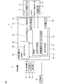
- FIG. 1 is a block diagram of a robot device according to an embodiment
- FIG. FIG. 4 is an enlarged perspective view of the work when fitting the first work to the second work
- 1 is a schematic diagram of a robot apparatus when the robot is in a first position and orientation
- FIG. FIG. 4 is a schematic diagram of the robotic device when the robot is in a second position and orientation
- It is a second image displayed on the display section of the teaching console.
- 1 is a block diagram of a simulation device in an embodiment
- FIG. It is an image displayed on the display unit of the simulation device.
- FIG. A computing device calculates an allowable value of an external force applied to a robot device or a workpiece gripped by the robot device.
- FIG. 1 is a schematic diagram of the robot device according to the present embodiment.
- the robot device 5 includes a hand 2 as a work tool and a robot 1 that moves the hand 2 .
- the robot 1 of this embodiment is an articulated robot including a plurality of joints 18a, 18b, and 18c.
- the robot 1 includes a plurality of moveable components. The components of robot 1 are configured to rotate about respective drive axes.
- the robot 1 of this embodiment includes a base portion 14 and a swivel base 13 that rotates with respect to the base portion 14 .
- Robot 1 includes upper arm 11 and lower arm 12 .
- the lower arm 12 is rotatably supported by the swivel base 13 .
- the upper arm 11 is rotatably supported by the lower arm 12 .
- the robot 1 includes a wrist portion 15 rotatably supported by the upper arm 11 .
- the hand 2 is fixed to the flange 16 of the wrist portion 15 . Additionally, the upper arm 11 or flange 16 rotates around a predetermined drive axis.
- the robot of this embodiment has six drive axes, it is not limited to this form. A robot that changes its position and orientation with any mechanism can be employed.
- the work tool of the present embodiment is a hand having two claws, it is not limited to this form. Any device suitable for the work performed by the robot device can be adopted as the work tool.
- a reference coordinate system 76 is set in the robot device 5 of the present embodiment.
- Reference coordinate system 76 is also referred to as the world coordinate system.
- the reference coordinate system 76 is a coordinate system in which the position of the origin is fixed and the directions of the coordinate axes are fixed.
- a tool coordinate system having an origin set at an arbitrary position of the work tool is set in the robot device 5 .
- the origin of the tool coordinate system is set at the tool tip point, which is the middle point between the tips of the two claws of the hand 2 .
- a tool coordinate system is a coordinate system that changes position and orientation with the work tool.
- the position of robot 1 corresponds to the position of the origin of the tool coordinate system in reference coordinate system 76 .
- the posture of the robot 1 corresponds to the orientation of the tool coordinate system with respect to the reference coordinate system 76 .
- FIG. 2 shows a block diagram of the robot device according to this embodiment.
- robot 1 includes a robot driving device that changes the position and posture of robot 1 .
- the robot drive includes robot drive motors 22 that drive components such as arms and wrists.
- a plurality of robot drive motors 22 are arranged corresponding to each drive shaft.
- the robot device 5 includes a hand driving device that drives the hand 2.
- the hand drive device includes a hand drive motor 21 that drives the claw portion of the hand 2 . As the hand driving motor 21 is driven, the claw portion of the hand 2 is opened and closed.
- the hand may be formed so as to be driven by air pressure or the like.
- the robot device 5 includes a control device 4 that controls the robot 1 and the hand 2.
- the control device 4 includes a control device main body 40 and a teaching operation panel 37 for operating the control device main body 40 by an operator.
- the control device body 40 includes an arithmetic processing device (computer) having a CPU (Central Processing Unit) as a processor.
- the arithmetic processing unit has a RAM (Random Access Memory), a ROM (Read Only Memory), etc., which are connected to the CPU via a bus.
- the teaching operation panel 37 is connected to the control device body 40 via a communication device.
- the teaching operation panel 37 includes an input section 38 for inputting information regarding the robot 1 and the hand 2 .
- the input unit 38 is composed of input members such as a keyboard and dials.
- the teaching operation panel 37 includes a display section 39 that displays information regarding the robot 1 and hand 2 .
- the display unit 39 can be configured by an arbitrary display panel such as a liquid crystal display panel or an organic EL (Electro Luminescence) display panel.
- the teaching console panel includes a touch panel type display panel, the display panel functions as an input section and a display section.
- An operation program 46 created in advance for operating the robot 1 and the hand 2 is input to the control device 4 .
- the operator can set the teaching point of the robot 1 by operating the teaching operation panel 37 to drive the robot 1 .
- the control device 4 can generate an operation program 46 based on the teaching points.
- the control device main body 40 includes a motion control section 43 that controls motions of the robot 1 and the hand 2 .
- the motion control section 43 sends a motion command for driving the robot 1 to the robot driving section 45 .
- Robot drive section 45 includes an electrical circuit that drives robot drive motor 22 .
- the robot driving section 45 supplies electricity to the robot driving motor 22 based on the operation command.
- the motion control unit 43 sends a motion command for driving the hand 2 to the hand driving unit 44 .
- the hand drive section 44 includes an electric circuit that drives the hand drive motor 21 .
- the hand drive unit 44 supplies electricity to the hand drive motor 21 based on the operation command.
- the control device main body 40 includes a storage section 42 that stores information regarding control of the robot 1 and hand 2 .
- the storage unit 42 can be configured by a non-temporary storage medium capable of storing information.
- the storage unit 42 can be configured with a storage medium such as a volatile memory, a nonvolatile memory, a magnetic storage medium, or an optical storage medium.
- the operating program 46 is stored in the storage unit 42 .
- the operation control unit 43 corresponds to a processor driven according to the operation program 46.
- the processor is formed so as to be able to read information stored in the storage unit 42 .
- the processor functions as the motion control unit 43 by reading the motion program 46 and controlling the robot 1 and the hand 2 determined by the motion program 46 .
- the processor also functions as an operation control unit 43 by driving the robot 1 and the hand 2 based on the operation of the input unit 38 of the teaching operation panel 37 .
- the robot 1 includes a state detector for detecting the position and orientation of the robot 1.
- the state detectors in this embodiment include position detectors 19 that detect the rotational position attached to the robot drive motors 22 of the respective drive shafts.
- the position detector 19 can be composed of an encoder that detects the rotation angle of the output shaft of the robot drive motor 22 .
- the position and posture of robot 1 are detected based on the outputs of a plurality of position detectors 19 .
- the control device 4 includes a force sensor 24 as a force detector attached to the robot 1.
- the force sensor 24 of this embodiment is a 6-axis sensor.
- the force sensor 24 is arranged between the flange 16 and the hand 2 .
- the force sensor 24 detects external forces including forces and moments acting on the workpiece 71 .
- any force sensor such as a sensor including a strain sensor or a capacitive sensor can be employed.
- a sensor coordinate system for detecting force acting on the sensor is set in the force sensor 24 in the present embodiment.
- Forces detected by the force sensor 24 include forces in directions of three mutually orthogonal axes in the sensor coordinate system and forces around the three axes. More specifically, the force sensor 24 detects forces in directions of orthogonal three axes (X-axis, Y-axis, and Z-axis) and forces in directions of axes (W-axis, P-axis, and R-axis) around the three axes.
- Moments (Mx, My, Mz) as forces are detected.
- FIG. 3 shows an enlarged perspective view of the first work and the second work in this embodiment.
- robot device 5 performs control to fit first work 71 to second work 72 .
- the robot device 5 is driven by the robot 1 to move the first work 71 toward the second work 72 .
- the first work 71 is inserted into the concave portion 72 a of the second work 72 as indicated by an arrow 91 .
- the first workpiece 71 of this embodiment has a cylindrical shape.
- the end surface of the first work 71 is planar.
- the second workpiece 72 has a rectangular parallelepiped shape.
- a second work 72 is fixed to a workbench 75 .
- the concave portion 72a of the second work 72 is formed in a cylindrical shape.
- the concave portion 72a has a shape corresponding to the shape of the first work 71 so that the first work 71 is fitted therein.
- the control device 4 performs control to fit the cylindrical work 71 into the recess 72 a of the work 72 .
- the central axis 71a of the work 71 and the central axis 72aa of the recess 72a are on the same line, the work 71 is smoothly inserted into the recess 72a of the work 72.
- the central axis 71a may deviate in position or posture with respect to the central axis 72aa.
- control device 4 performs force control based on the output of the force sensor 24 when fitting the workpiece 71 into the recess 72a.
- control for adjusting the position and posture of the robot based on the force detected by the force detector is called force control.
- Force control utilizes the force generated when the workpieces come into contact with each other.
- the control device 4 Based on the force detected by the force sensor 24 as a force detector, the control device 4 performs control to change the speed in the direction perpendicular to the moving direction of the work and control to change the orientation of the work. be able to.
- the control device 4 can perform compliance control, impedance control, or the like based on the force detected by the force sensor 24, for example.
- a control point corresponds to an action point at which an external force acts on the robot device 5 or the workpiece 71 .
- a work tip point 73 is predetermined as a control point on the end face of the first work 71 .
- the workpiece tip point 73 is arranged at the center of the planar circle on the end surface of the first workpiece 71 .
- a direction indicated by an arrow 74 is set in advance as a movement direction of the work 71 supported by the robot 1 when fitting the work 71 into the recess 72a.
- the force sensor 24 detects an external force acting on the point of action.
- the robot device 5 of the present embodiment includes a calculation device that calculates the allowable value of external force.
- the control device body 40 of the control device 4 functions as a computing device.
- the control device body 40 includes a processing section 51 that performs arithmetic processing.
- the processing unit 51 includes an allowable force calculation unit 54 that calculates an allowable value of external force that is allowed to act on the robot, workpiece, or work tool.
- the processing unit 51 includes a movable range calculation unit 55 that calculates the region of the position of the action point where the current target value of the external force is equal to or less than the allowable value when the position and posture of the robot 1 change.
- the processing unit 51 includes a model generation unit 56 that generates a model of the robot device and a model of the work based on the three-dimensional shape data 58 of the robot device and the work.
- Processing unit 51 includes a display control unit 57 that controls an image displayed on display unit 39 of teaching operation panel 37 .
- the operation program 46 includes a program for performing calculations regarding the allowable value of external force and generating a model of the constituent members of the robot device.
- the processing unit 51 corresponds to a processor driven according to the operating program 46 .
- the processor functions as the processing unit 51 by executing control defined in the operating program 46 .
- each unit of the allowable force calculation unit 54 , the movable range calculation unit 55 , the model generation unit 56 , and the display control unit 57 corresponds to a processor driven according to the operation program 46 .
- Each unit functions by the processor executing the control defined in the operating program 46 .
- the motion control unit 43 performs force control based on the motion program 46.
- the motion control section 43 acquires the output of the force sensor 24 .
- the motion control unit 43 calculates an external force in a predetermined direction of action at the work tip point 73 as the point of action. For example, the motion control unit 43 sets an axis in the movement direction indicated by an arrow 74 and an axis orthogonal to the movement direction.
- the motion control unit 43 calculates the force applied in the direction of these axes and the moment around the axes as external forces acting on the workpiece tip point 73 .
- the motion control unit 43 can control the motion of the robot 1 so that the external force acting on the workpiece tip point 73 reaches a predetermined target value. For example, when the workpiece 71 is moved in the moving direction indicated by the arrow 74 and the workpiece 71 contacts the workpiece 72, the motion control unit 43 controls the force acting in the direction opposite to the moving direction indicated by the arrow 74 to be the target value. to control the position and attitude of the robot 1. In other words, the motion control unit 43 controls the position and posture of the robot 1 so that the force pressing the workpiece 71 in the direction indicated by the arrow 74 becomes a target value. In addition, the motion control unit 43 controls the robot 1 so that the forces in the directions of the axes perpendicular to the directions indicated by the arrows 74 and the moments around these axes reach predetermined target values.
- the motion control unit 43 can perform force control to control the motion of the robot so that the external force acting on the point of action in the predetermined direction of action reaches the target value.
- the fitting operation can be performed while correcting the position and posture of the first work 71 with respect to the recess 72a.
- a target value of the external force is set in the operation program 46 as a parameter for implementing force control.
- the first work 71 comes into contact with the second work 72 as another object when performing the fitting work. Then, the position and attitude of the work 71 are adjusted based on the external force acting on the work 71 .
- a load is applied to the constituent members of the robot 1 and the hand 2 while the work 71 is in contact with the work 72 .
- tensile force, compressive force, bending moment, torsional moment, and the like are applied as loads to respective constituent members such as upper arm 11, lower arm 12, swivel base 13, and wrist portion 15.
- torque around the rotation axis is applied as a load to the constituent members such as the robot drive motor 22 and the speed reducer arranged at each of the joints 18a, 18b, and 18c.
- torque is applied to the torque sensor as a load.
- the allowable value of the load that can be applied to the constituent members of the robot 1 is predetermined. If the load on the constituent members exceeds the allowable value, there is a risk that each constituent member will malfunction. For example, components may break or malfunction. As a result, there is a possibility that the robot device will not operate normally.
- the robot device It is preferable to drive the robot device so that the load applied to its constituent members is below the allowable value. In particular, it is preferable to drive the robot so that the load acting on each component does not exceed physical or mechanical tolerances.
- Physical allowable values correspond to allowable values of torsional moment, bending moment, compressive force, tensile force, etc. acting on a component member such as an arm.
- the mechanical allowable value corresponds to an allowable value such as torque or compressive force acting on a component composed of a plurality of parts such as bearings and speed reducers.
- the allowable value for the safety function corresponds to the allowable value for stopping the robot when it contacts another object.
- the load applied to each component is below the allowable value.
- a load corresponding to the force when pressing the first work 71 against the second work is generated in each of the constituent members.
- the target value of the external force it is preferable to set the target value of the external force to an appropriate value so that the force acting on the workpiece tip point 73 does not become too large.
- FIG. 4 shows a schematic diagram of the robot device when the robot is in the first position and posture.
- FIG. 5 shows a schematic diagram of the robot apparatus when the robot is in the second position and orientation. 4 and 5, each figure shows a contact surface 89 with which the first workpiece 71 contacts.
- the contact surface 89 corresponds to the surface of the object against which the first workpiece 71 is pressed.
- the robot 1 presses the first workpiece 71 toward the contact surface 89 with a constant force along the moving direction indicated by the arrow 74 . That is, the external force acting on the workpiece tip point 73 is the same between the first position and posture and the second position and posture.
- the torque applied to the constituent members such as the torque sensor arranged in the joint portion 18a depends on the external force acting on the workpiece tip point 73 and the distance from the workpiece tip point 73 to the drive shaft of the joint portion 18a.
- the distance from the drive shaft of the joint portion 18a to the workpiece tip point 73 at the second position and posture is longer than the distance from the drive shaft of the joint portion 18a to the workpiece tip point 73 at the first position and posture. Therefore, with respect to the torque applied to the constituent members arranged in the joint portion 18a, the torque at the second position and posture is greater than the torque at the first position and posture.
- the bending moment at the second position and posture is larger than the bending moment at the first position and posture.
- the load acting on the structural members of the robot device changes according to the position and posture of the robot.
- the torque applied to the components arranged in the joint portion 18a is maximized at the position and posture of the robot where the position of the workpiece tip point 73 is the furthest from the drive shaft of the joint portion 18a.
- a certain allowable value of external force was determined so that the load acting on the constituent members of the robot device was below the allowable value in various robot positions and postures. For example, as shown in FIG. 5, when the upper arm 11 and the lower arm 12 are greatly extended, the allowable value of the external force is set so that the torque applied to the joint portion 18a is below the allowable value. For this reason, an allowable value for a small external force has been set.
- the target value of the external force is determined based on the allowable value of the external force, a small target value of the external force is adopted. For example, in the first position and orientation shown in FIG. 4, although a large external force can be applied to the workpiece tip point 73, the target value of the small external force set based on the second position and orientation shown in FIG. The robot is driven by As a result, the working time of the robot device may become long.
- control device 4 in the present embodiment calculates the allowable value of external force according to the state in which the robot device is driven.
- the allowable force calculation unit 54 of the processing unit 51 calculates the allowable value of external force that can be applied to the point of action based on the position and orientation of the robot.
- the permissible force calculation unit 54 calculates the permissible value of the external force in the direction in which the external force acts, based on the position of the point of action on which the external force acts and the permissible value of the load of the constituent members of the robot.
- the permissible value of the external force acting on the tip end point 73 of the workpiece is calculated when force control is performed.
- the worker can obtain the allowable value of the external force during teaching work.
- the operator manually operates the robot 1 to bring the first work 71 into contact with the surface of the second work 72 .
- the operator operates the teaching operation panel 37 to change the position and posture of the robot so that the first work 71 contacts the second work 72 .
- the allowable force calculation unit 54 acquires the position and posture of the robot based on the output of the position detector 19.
- the allowable force calculation unit 54 acquires the position of the work tip point 73 as the point of action on which the external force acts.
- the workpiece tip point 73 moves together with the first workpiece 71 and the hand 2 .
- the robot device 5 is calibrated so that the position of the workpiece tip point 73 can be calculated when the position and posture of the robot are determined.
- the position of the workpiece tip point 73 is determined in advance by the coordinate values of the tool coordinate system.
- a flange coordinate system having an origin at the flange 16 of the robot 1 and moving together with the flange 16 can be set.
- the position of the workpiece tip point 73 can be determined in advance in the flange coordinate system.
- the allowable force calculation unit 54 can calculate the position of the work tip point 73 in the reference coordinate system 76 based on the position of the work tip point 73 in the tool coordinate system or the flange coordinate system and the position and posture of the robot 1. .
- the permissible force calculator 54 also detects the acting direction of the external force based on the output of the force sensor 24 . Alternatively, a predetermined direction may be adopted as the acting direction of the external force.
- the load applied to each component of the robot 1 can be calculated. Constants necessary for load calculation, such as the shape, size and weight of each component, are stored in advance in the storage unit 42 .
- the position and orientation of each component such as an arm can be calculated based on the position and orientation of the robot 1 .
- the positions of the joints 18a, 18b, and 18c can be calculated from the position and orientation of the robot 1.
- the allowable force calculation unit 54 calculates loads such as tensile force, compressive force, bending moment, and torsional moment in constituent members such as the upper arm 11 and the lower arm 12 based on a predetermined external force and the direction of action of the external force. can be calculated. In addition, the allowable force calculator 54 can calculate the torque applied to the constituent members arranged at the joints 18a, 18b, and 18c. Each load calculation method is determined in advance and stored in the storage unit 42 . The allowable force calculator 54 can calculate the load applied to each component based on the position and orientation of each component.
- the allowable force calculation unit 54 calculates the load applied to the constituent member while gradually increasing the external force applied to the workpiece tip point 73 in a predetermined direction of action from a small initial value. For example, the allowable force calculator 54 gradually increases the external force applied to the workpiece tip point 73 from zero by a predetermined increase amount in the moving direction indicated by the arrow 74 . A load applied to each component of the robot apparatus is calculated. Then, the allowable force calculation unit 54 detects that the load of at least one of the plurality of constituent members exceeds the allowable value of the load. Based on the external force at this time, the allowable force calculator 54 can determine the allowable value of the external force at which the loads of all the constituent members are within the allowable value.
- the allowable force calculation unit 54 determines the maximum value of the external force when the loads of all the constituent members are within the allowable value when the external force applied to the workpiece tip point 73 is gradually increased, as the allowable value of the external force. be able to.
- the allowable value of the external force acting on the point of action can be calculated according to the position of the point of action, the direction in which the external force acts, and the position and posture of the robot.
- the direction in which the allowable value of the external force is calculated is not limited to the form described above. Any method can be used to calculate the allowable value of the external force so that the loads of all the constituent members do not exceed the allowable value.
- the allowable force calculation unit 54 acquires an allowable load value that can be applied to each component.
- the allowable force calculation unit 54 calculates the allowable value of external force that can be applied in the action direction at the tip end point 73 of the workpiece from the allowable values of the loads of the constituent members based on the position and orientation of the robot.
- the allowable force calculation unit 54 calculates the allowable value of the external force at the tip end point 73 of the workpiece with respect to the allowable values of the loads of all the constituent members.
- the allowable force calculation unit 54 can adopt the smallest allowable value of external force among the allowable values of the external force for the allowable values of the loads of all the constituent members as the allowable value of the external force that can be applied to the tip end point 73 of the workpiece. .
- the display control unit 57 displays the allowable value of the external force calculated by the allowable force calculation unit 54 on the display unit 39 of the teaching operation panel 37.
- the operator can see the permissible value of the external force and determine the target value of the external force when performing force control.
- the target value of the external force can be set to be equal to or less than the allowable value of the external force.
- the operator can adopt a value slightly smaller than the allowable value of the external force as the target value of the external force.
- the operator can set the target value of the external force in the operation program.
- the permissible value of the external force calculated by the processing unit 51 in this embodiment includes the position and posture of the robot, the permissible value of the load of each component, the position of the point of action where the external force acts, and the direction of action of the external force. Based on For this reason, it is possible to set the target value of the external force that the robot apparatus can apply to the workpiece according to the state of the robot. In particular, it is possible to set the target value of the external force according to the position and posture of the robot. Therefore, it is possible to avoid setting the external force target value to a small value for all positions and postures of the robot. Alternatively, it is possible to prevent the robot device from automatically stopping due to the target value of the external force being too large.
- a target value of external force larger than that of the conventional technology is set, or the robot is driven with an allowable value of external force larger than that of the conventional technology. be able to. Therefore, it is possible to shorten the working time of the robot device.
- the force for pressing the first workpiece 71 against the second workpiece 72 can be increased, and the operation of fitting the workpieces can be performed in a shorter time than the conventional technique. can be implemented.
- the motion control unit 43 of this embodiment can control the motion of the robot so that the magnitude of the external force acting on the point of action is equal to or less than the allowable value of the external force.
- the motion control unit 43 of the present embodiment can control the motion of the robot 1 so that the external force acting on the workpiece tip point 73 becomes the target value of the external force.
- the allowable value of the external force acting on the action point may be set in the operation program.
- the motion control unit calculates the external force acting on the point of action based on the output of the force sensor while the robot is being driven. When the external force acting on the point of action approaches the allowable value, the motion control unit controls the driving state of the robot, such as the operating speed of the robot or the position and orientation of the robot, so that the force acting on the point of action becomes smaller. can do.
- FIG. 6 shows a first image displayed on the display section of the teaching console in this embodiment.
- three-dimensional shape data 58 of the constituent members and workpieces that make up the robot apparatus are created in advance.
- the three-dimensional shape data 58 for example, data output from a CAD (Computer Aided Design) device can be used.
- the three-dimensional shape data 58 are stored in the storage unit 42 . Further, the positions of the first work 71 and the second work 72 with respect to the actual robot device 5 are determined and set in advance.
- the model generation unit 56 generates a three-dimensional model of the robot device and the work based on the three-dimensional shape data of the robot device and the three-dimensional shape data of the work.
- the model generation unit 56 acquires the position and orientation of the robot 1 based on the output of the position detector 19 .
- a three-dimensional model is generated that corresponds to the position and pose of the robot.
- the model generator 56 arranges the model in the virtual space according to the actual position of the robot device and the position of the workpiece.
- the display control unit 57 displays the model image generated by the model generation unit 56 on the display unit 39 .
- the display control unit 57 generates an image of the model when viewed from a predetermined direction.
- a robot model 1M, a force sensor model 24M, a hand model 2M, a first workpiece model 71M, and a second workpiece model 72M are displayed.
- the position and orientation of the robot model 1M in the image 81 also change.
- the display control unit 57 of the present embodiment can display the allowable value of the external force calculated by the allowable force calculation unit 54 superimposed on the image of the robot 1 .
- a model 73M of the tip point of the workpiece and an arrow 74M indicating the acting direction of the external force are displayed.
- "MAX: 50N" is displayed as the allowable value of the external force that can be applied to the tip of the workpiece as the point of action. That is, it is displayed that the allowable value of the external force is 50N at the current position and orientation of the robot.
- the permissible value of the external force also changes.
- the operator can look at the image 81 and determine the target value of the external force when performing force control. For example, the operator can set the same value as the allowable value of the external force in the operation program 46 as the target value.
- the processing unit 51 may automatically set the target value of the external force in the operation program 46 based on the allowable value of the external force calculated by the allowable force calculation unit 54 . As the target value of the external force, a value equal to or less than the allowable value of the external force can be set.
- the allowable value of external force is set in the operation program.
- the operator can set the allowable value of the external force calculated by the allowable force calculator 54 in the operation program.
- the processing unit 51 may automatically set the allowable value of the external force calculated by the allowable force calculation unit 54 to the operation program.
- the display unit 39 indicates the allowable value of the external force by a number next to the arrow indicating the direction of action of the external force, but it is not limited to this form.
- the display unit may indicate the allowable value of the external force by the length of the arrow. For example, the display unit can display a longer arrow as the allowable value of the external force increases.
- Fig. 7 shows the second image displayed on the display section of the teaching operation panel.
- a robot model 1M a visual sensor model 24M, a hand model 2M, and a first workpiece model 71M are displayed.
- movable range calculator 55 calculates a region 87M of the position of the point of action where the current target value of the external force is equal to or less than the allowable value of the external force when the position and posture of the robot change. do.
- the movable range calculator 55 calculates a region 87M in which the position and posture of the robot can be changed with a predetermined target value of the external force.
- a region 87M is a range in which the point of action can move.
- the display control unit 57 displays the area 87M superimposed on the image of the robot.
- an area 87M in which the point of action can be moved is shown within a plane where the height from the installation surface of the robot 1 to the point of action is constant. Note that the region in which the point of action can move may be searched for and displayed in a three-dimensional region.
- the movable range calculator 55 acquires the current position of the point of action.
- the movable range calculator 55 acquires the current position of the point of action in the reference coordinate system 76 .
- a plane with a constant height from the installation surface is considered as the movable range of the point of action.
- the movable range calculator 55 moves the position of the work tip point as the point of action in a plane by a predetermined direction and a predetermined distance.
- the allowable force calculator 54 calculates the allowable value of the external force at the position of each action point.
- the movable range calculation unit 55 determines that the point of action can move to that position.
- the movable range calculator 55 determines that the point of action cannot move to that position.
- the movable range calculator 55 performs control to move the position of the point of action little by little.
- the movable range calculator 55 can calculate the region of the position of the point of action where the allowable value of the external force is equal to or greater than the target value of the external force.
- the display control unit 57 can acquire the position to which the point of action can be moved from the movable range calculation unit 55, and display the area 87M.
- the operator can confirm the range in which the point of action can be moved on the image 82 .
- the operator can easily grasp the range in which the current target value of the external force can be adopted. In this manner, the operator can set the target value of the external force for force control while manually driving the robot device 5 using the teaching operation panel 37 .
- the control device 4 can automatically set or change the target value of the external force based on the position and orientation of the robot during force control.
- allowable force calculation unit 54 of processing unit 51 acquires the position and orientation of the robot based on the output of position detector 19 while force control is being performed.
- the permissible force calculation unit 54 calculates the current permissible value of the external force based on the current position and orientation of the robot.
- the allowable force calculator 54 can calculate the allowable value of the external force for each predetermined interval. Alternatively, when performing force control, the allowable value of the external force may be calculated for one position and posture of the robot.
- the processing unit 51 calculates the target value of the external force when performing force control based on the allowable value of the external force. For example, the processing unit 51 can set the allowable value of the external force to the target value of the external force. Alternatively, the processing unit 51 may set the target value of the external force by multiplying the allowable value of the external force by a predetermined constant less than one. The processing unit 51 sends the target value of the external force set based on the allowable value of the external force to the operation control unit 43 . The motion control unit 43 can perform force control to bring the first workpiece into contact with another object based on the acquired target value of the external force. By performing this control, it is possible to set or change the target value of the external force according to the position and posture of the robot while the robot is performing a predetermined task. Since the work can be performed with the optimum external force target value, the work time can be shortened.
- the processing unit 51 can perform control to issue a warning to notify the operator.
- the allowable force calculation unit 54 calculates the allowable value of the external force.
- the processing unit 51 can display a warning on the display unit.
- the processing unit 51 can notify the operator by an alarm or the like. The operator can avoid setting too large a target value of the external force.
- the motion control unit 43 can perform control to stop the robot 1 when the target value of the external force exceeds the allowable value of the external force while the robot 1 is being driven.
- the target value of the external force may be predetermined in the operation program 46 .
- the allowable force calculator 54 calculates the allowable value of the external force while the robot is driving. Then, when the target value of the external force exceeds the allowable value of the external force, the motion control section 43 can perform control to stop the robot 1 .
- FIG. 8 shows a block diagram of a simulation device according to this embodiment.
- the computing device of this embodiment can be arranged in a simulation device.
- the simulation device 6 arranges the three-dimensional model of the robot, the three-dimensional model of the working tool, and the three-dimensional model of the workpiece in the same virtual space.
- the simulation device 6 of the present embodiment simulates the motion of the robot device 5 described above.
- the simulation device 6 in the present embodiment is composed of an arithmetic processing device (computer) including a CPU as a processor.
- the simulation device 6 includes a storage unit 63 that stores arbitrary information regarding simulation of the robot device 5 .
- the storage unit 63 can be configured by a non-temporary storage medium capable of storing information.
- the storage unit 63 can be configured with a storage medium such as a volatile memory, a nonvolatile memory, a magnetic storage medium, or an optical storage medium.
- a program for simulating the robot apparatus is stored in the storage unit 63 .
- the simulation device 6 includes an input unit 61 for inputting information regarding simulation of the robot device 5 .
- the input unit 61 is composed of operating members such as a keyboard, mouse, and dial.
- the simulation device 6 includes a display section 62 that displays information regarding simulation of the robot device 5 .
- the display unit 62 is composed of an arbitrary display panel such as a liquid crystal display panel or an organic EL display panel. Note that when the simulation apparatus includes a touch panel type display panel, the display panel functions as an input unit and a display unit.
- the simulation device 6 functions as a calculation device that calculates the allowable value of the external force acting on the point of action.
- the simulation device 6 includes a processing unit 64 that performs arithmetic processing for simulating the robot device 5 . Similar to the processing unit 51 of the robot control device 4 of the present embodiment, the processing unit 64 includes a model generation unit 56 that generates a model based on the three-dimensional shape data 58, an allowable force calculation unit that calculates an allowable value of external force, and a 54, and a movable range calculator 55 that calculates the range in which the robot can be driven with a predetermined target value of the external force (see FIG. 2).
- the three-dimensional shape data 58 of the constituent members and workpieces constituting the robot device are input to the simulation device 6 (see FIG. 2).
- the three-dimensional shape data 58 are stored in the storage section 63 .
- the processing unit 64 includes a simulation execution unit 65 that simulates the motion of the robot device 5 .
- the simulation execution unit 65 has a function of moving the model of the robot device. Alternatively, the simulation execution unit 65 simulates the motion of the robot device 5 based on the motion program 46 created in advance.
- Processing unit 64 includes a display control unit 66 that controls an image displayed on display unit 62 based on the output of simulation execution unit 65 .
- the processing unit 64 corresponds to a processor driven according to a program for executing simulation.
- the processor functions as the processing unit 64 by reading the simulation program and performing control determined by the program.
- each unit of the model generation unit 56, the simulation execution unit 65, the allowable force calculation unit 54, the movable range calculation unit 55, and the display control unit 66 included in the processing unit 64 corresponds to a processor driven according to the simulation program. do.
- the processors function as respective units by executing control defined in the program.
- Fig. 9 shows an example of an image displayed on the display unit of the simulation device.
- the display unit 62 of the simulation device 6 displays a three-dimensional model image similar to the display unit 39 of the robot control device 4 .
- a worker can input design values for the position where the robot is installed and the position where the work is arranged through the input unit 61 . Also, the position of the workpiece with respect to the robot is preset by the operator.
- the image 83 displays a robot model 1M, a force sensor model 24M, a hand model 2M, a first workpiece model 71M, and a second workpiece model 72M.
- the simulation execution unit 65 calculates the current position and orientation of the robot 1 according to the operation of the input unit 61 by the operator. Alternatively, the simulation execution unit 65 calculates the position and orientation of the robot at a predetermined time based on the motion program 46 .
- the model generator generates a robot model 1M based on the position and orientation of the robot.
- the display control unit 66 displays a model image on the display unit 62 according to the output of the simulation execution unit 65 and the three-dimensional model generated by the model generation unit 56 .
- the simulation device 6 can calculate the allowable value of the external force while simulating the motion of the robot device 5 .
- the position of the point of action can be determined in advance and designated by the operator.
- the direction of action of the external force acting on the point of action can predetermine a plurality of directions and carry out the simulation.
- the allowable force calculator 54 can calculate the allowable value of the external force acting on the point of action based on the position and orientation of the robot.
- the display unit 62 of the simulation device 6 displays the allowable value of the external force calculated by the allowable force calculation unit 54, and the action point calculated by the movable range calculation unit 55. A region of locations can be displayed (see FIGS. 6 and 7).
- simulations can be performed without using the actual robot device. Therefore, when generating an operation program off-line, it is possible to calculate the allowable value of the external force and the range in which the action point can move. Moreover, it can be used for designing a system including a robot device. For example, it is possible to consider the positions for arranging peripheral devices such as a robot device and a pedestal.
- the display unit in the present embodiment is a display panel arranged on the teaching operation panel or a display panel arranged on the simulation device.
- the display unit may be composed of, for example, a display panel of a tablet terminal.
- the display section may be composed of a display panel arranged in a personal computer.
- the display unit may be located in a computer that generates images of augmented reality.
- augmented reality image for example, the allowable value of the external force can be displayed on the image of the robot device captured by the tablet terminal.
- the processing unit of the simulation apparatus of the present embodiment is composed of an arithmetic processing unit separate from the robot control unit, but is not limited to this form.
- the robot control device may have the function of the simulation device. That is, the processor of the arithmetic processing unit of the control device may have the function of the processing section of the simulation device.
- the teaching console panel may have the function of a simulation device. That is, the processor of the teaching console may function as the processing section of the simulation device.
- the point of action where the external force acts is set on the workpiece, but the point of action is not limited to this form, and the point of action can be set at any position on the robot or work tool. Also in this case, the calculation device can calculate the allowable value of the external force acting in the action direction at the point of action.
- a 6-axis force sensor is arranged on the wrist as a force detector, but the present invention is not limited to this form. Any sensor capable of detecting an external force acting on the point of action can be employed as the force detector.
- a torque sensor may be arranged at the joint of the robot. A plurality of torque sensors are arranged on the drive shafts of the plurality of joints of the robot. Each torque sensor detects torque about the drive shaft of the joint.
- the force sensor may be arranged on the base of the robot.
- control for fitting a cylindrical work is shown, but the control of the present embodiment can be applied to works of any shape. Also, in the present embodiment, control for fitting one work to another work is exemplified, but the present invention is not limited to this form.
- the control device and the simulation device of the present embodiment can be applied to a robot device that performs work in which one work contacts another object.
- the fitting work is not limited to the work of inserting the workpiece into the recess or the hole. For example, it involves placing the gear in place while phasing the teeth of the gear.
Landscapes
- Engineering & Computer Science (AREA)
- Robotics (AREA)
- Mechanical Engineering (AREA)
- Physics & Mathematics (AREA)
- General Physics & Mathematics (AREA)
- Theoretical Computer Science (AREA)
- Human Computer Interaction (AREA)
- Business, Economics & Management (AREA)
- Emergency Management (AREA)
- Manipulator (AREA)
Abstract
Description
2 ハンド
4 制御装置
6 シミュレーション装置
11 上部アーム
12 下部アーム
13 旋回ベース
14 ベース部
15 手首部
18a,18b,18c 関節部
24 力覚センサ
37 教示操作盤
39,62 表示部
40 制御装置本体
43 動作制御部
51,64 処理部
54 許容力算出部
55 可動範囲算出部
71,72 ワーク
73 ワーク先端点
81,82 画像
74M 矢印
87M 領域
Claims (9)
- ロボット、ワーク、または作業ツールに対して作用することが許容される外力の許容値を算出する処理部を備え、
ロボットの構成部材に対して加えることができる負荷の許容値が予め定められており、
前記処理部は、ロボットの位置および姿勢、外力が作用する作用点の位置、ロボットの構成部材の負荷の許容値に基づいて、外力が作用する作用方向における外力の許容値を算出する、計算装置。 - ロボットの画像を表示する表示部を備え、
前記表示部は、前記処理部にて算出された外力の許容値をロボットの画像に重ねて表示する、請求項1に記載の計算装置。 - ロボットの画像を表示する表示部を備え、
作用点において予め定められた前記作用方向に作用する外力の目標値が予め定められており、
前記処理部は、ロボットの位置および姿勢が変化した時に現在の目標値が外力の許容値以下になる作用点の位置の領域を算出し、
前記表示部は、現在の目標値が外力の許容値以下になる作用点の位置の領域をロボットの画像に重ねて表示する、請求項1に記載の計算装置。 - 前記表示部は、タブレット端末、パーソナルコンピュータ、ロボットの動作を手動で操作する教示操作盤、または拡張現実の画像を生成するコンピュータのいずれかに配置されている、請求項2または3に記載の計算装置。
- 請求項1に記載の計算装置と、
ロボットの動作を制御する動作制御部とを備える、ロボットの制御装置。 - 作用点に作用する外力を検出する力検出器を備え、
前記動作制御部は、作用点に作用する外力が許容値以下になるようにロボットの動作を制御する、請求項5に記載のロボットの制御装置。 - 作用点に作用する外力を検出する力検出器を備え、
前記動作制御部は、作用点において予め定められた作用方向に作用する外力が予め定められた目標値になるようにロボットの動作を制御し、
前記処理部は、前記作用方向における外力の許容値を算出する、請求項5に記載のロボットの制御装置。 - 作業者が外力の目標値を設定する時に、外力の目標値が外力の許容値を超えている場合に作業者に知らせるための警告を発生する、請求項7に記載のロボットの制御装置。
- 前記動作制御部は、ロボットを駆動している期間中に外力の目標値が外力の許容値を超えた場合にロボットを停止させる、請求項5から8のいずれか一項に記載のロボットの制御装置。
Priority Applications (4)
| Application Number | Priority Date | Filing Date | Title |
|---|---|---|---|
| DE112022000610.2T DE112022000610T5 (de) | 2021-03-31 | 2022-03-24 | BERECHNUNGSVORRICHTUNG ZUR BERECHNUNG DES ZULÄSSIGEN WERTES EINER AUF EINEN ROBOTER ODER EIN WERKSTÜCK WIRKENDEN ÄUßEREN KRAFT UND VORRICHTUNG ZUR STEUERUNG EINES ROBOTERS |
| CN202280023641.1A CN117042935A (zh) | 2021-03-31 | 2022-03-24 | 计算作用于机器人装置或工件的外力的容许值的计算装置以及机器人的控制装置 |
| US18/262,577 US12496732B2 (en) | 2021-03-31 | 2022-03-24 | Computation device for calculating permissible value of external force acting on robot device or workpiece, and device for controlling robot |
| JP2023511139A JP7481579B2 (ja) | 2021-03-31 | 2022-03-24 | ロボット装置またはワークに作用する外力の許容値を算出する計算装置およびロボットの制御装置 |
Applications Claiming Priority (2)
| Application Number | Priority Date | Filing Date | Title |
|---|---|---|---|
| JP2021060816 | 2021-03-31 | ||
| JP2021-060816 | 2021-03-31 |
Publications (1)
| Publication Number | Publication Date |
|---|---|
| WO2022210291A1 true WO2022210291A1 (ja) | 2022-10-06 |
Family
ID=83458878
Family Applications (1)
| Application Number | Title | Priority Date | Filing Date |
|---|---|---|---|
| PCT/JP2022/014108 Ceased WO2022210291A1 (ja) | 2021-03-31 | 2022-03-24 | ロボット装置またはワークに作用する外力の許容値を算出する計算装置およびロボットの制御装置 |
Country Status (6)
| Country | Link |
|---|---|
| US (1) | US12496732B2 (ja) |
| JP (1) | JP7481579B2 (ja) |
| CN (1) | CN117042935A (ja) |
| DE (1) | DE112022000610T5 (ja) |
| TW (1) | TWI883313B (ja) |
| WO (1) | WO2022210291A1 (ja) |
Citations (2)
| Publication number | Priority date | Publication date | Assignee | Title |
|---|---|---|---|---|
| JP2016168650A (ja) * | 2015-03-13 | 2016-09-23 | キヤノン株式会社 | ロボット装置、ロボット制御方法、プログラム及び記録媒体 |
| JP2019202381A (ja) * | 2018-05-23 | 2019-11-28 | セイコーエプソン株式会社 | ロボット制御装置およびロボットシステム |
Family Cites Families (19)
| Publication number | Priority date | Publication date | Assignee | Title |
|---|---|---|---|---|
| JPH05158526A (ja) * | 1991-12-04 | 1993-06-25 | Yaskawa Electric Corp | ロボット関節負荷の表示方法 |
| JP3961408B2 (ja) * | 2002-11-21 | 2007-08-22 | ファナック株式会社 | 組立て方法及び装置 |
| JP4449693B2 (ja) * | 2004-10-22 | 2010-04-14 | パナソニック株式会社 | ロボット制御装置およびその制御方法 |
| JP5458274B2 (ja) | 2009-02-09 | 2014-04-02 | 本田技研工業株式会社 | 把持位置計算装置及び把持位置計算方法 |
| JP5481919B2 (ja) * | 2009-04-24 | 2014-04-23 | 株式会社Ihi | ワーク加工装置とその制御方法 |
| JP5855423B2 (ja) * | 2011-11-01 | 2016-02-09 | オリンパス株式会社 | 手術支援装置 |
| JP5966320B2 (ja) * | 2011-11-04 | 2016-08-10 | 株式会社ニコン | 駆動装置、ロボット装置及び駆動方法 |
| JP5896003B1 (ja) * | 2014-10-29 | 2016-03-30 | 株式会社安川電機 | 加工装置、教示方法、ワークの生産方法、コントローラ及び制御方法 |
| GB201419645D0 (en) * | 2014-11-04 | 2014-12-17 | Cambridge Medical Robotics Ltd | Characterising motion constraints |
| JP6046218B1 (ja) | 2015-07-09 | 2016-12-14 | ファナック株式会社 | 物体と物体とを合わせ状態にするロボットのロボット制御装置 |
| JP6778199B2 (ja) * | 2015-08-25 | 2020-10-28 | 川崎重工業株式会社 | 遠隔操作ロボットシステム |
| WO2018144636A1 (en) * | 2017-02-01 | 2018-08-09 | Intuitive Surgical Operations, Inc. | Systems and methods of registration for image-guided procedures |
| JP6748019B2 (ja) | 2017-04-10 | 2020-08-26 | ファナック株式会社 | 外力表示機能を有するロボットシステム、処理装置及び教示操作盤 |
| JP6445114B2 (ja) * | 2017-10-27 | 2018-12-26 | ファナック株式会社 | 外力監視機能を有するワーク搬送方法システム |
| JP7028196B2 (ja) * | 2019-01-15 | 2022-03-02 | オムロン株式会社 | ロボット制御装置、ロボット制御方法、及びロボット制御プログラム |
| JP7290472B2 (ja) * | 2019-05-29 | 2023-06-13 | ファナック株式会社 | ロボットシステム |
| WO2021151066A1 (en) * | 2020-01-24 | 2021-07-29 | The Cleveland Clinic Foundation | Compliance correction in a robotic system |
| GB2593740B (en) * | 2020-03-31 | 2024-08-14 | Cmr Surgical Ltd | Control system of a surgical robot |
| CN112223298B (zh) * | 2020-12-08 | 2021-03-05 | 成都卡诺普自动化控制技术有限公司 | 一种确定机器人关节最大加速度和最大速度的方法 |
-
2022
- 2022-03-14 TW TW111109237A patent/TWI883313B/zh active
- 2022-03-24 CN CN202280023641.1A patent/CN117042935A/zh active Pending
- 2022-03-24 WO PCT/JP2022/014108 patent/WO2022210291A1/ja not_active Ceased
- 2022-03-24 DE DE112022000610.2T patent/DE112022000610T5/de active Pending
- 2022-03-24 JP JP2023511139A patent/JP7481579B2/ja active Active
- 2022-03-24 US US18/262,577 patent/US12496732B2/en active Active
Patent Citations (2)
| Publication number | Priority date | Publication date | Assignee | Title |
|---|---|---|---|---|
| JP2016168650A (ja) * | 2015-03-13 | 2016-09-23 | キヤノン株式会社 | ロボット装置、ロボット制御方法、プログラム及び記録媒体 |
| JP2019202381A (ja) * | 2018-05-23 | 2019-11-28 | セイコーエプソン株式会社 | ロボット制御装置およびロボットシステム |
Also Published As
| Publication number | Publication date |
|---|---|
| US20240091957A1 (en) | 2024-03-21 |
| US12496732B2 (en) | 2025-12-16 |
| JPWO2022210291A1 (ja) | 2022-10-06 |
| TW202239550A (zh) | 2022-10-16 |
| JP7481579B2 (ja) | 2024-05-10 |
| CN117042935A (zh) | 2023-11-10 |
| TWI883313B (zh) | 2025-05-11 |
| DE112022000610T5 (de) | 2023-11-30 |
Similar Documents
| Publication | Publication Date | Title |
|---|---|---|
| US9149931B2 (en) | Robot system, robot control device and method for controlling robot | |
| CN103302667B (zh) | 机器人控制方法、机器人控制装置和机器人控制系统 | |
| US10864632B2 (en) | Direct teaching method of robot | |
| CN110524536B (zh) | 机器人控制装置以及机器人系统 | |
| JP6683671B2 (ja) | ジョグ座標系を設定するロボットの制御装置 | |
| US20180111266A1 (en) | Control device, robot, and robot system | |
| KR20180059888A (ko) | 로봇교시방법 및 로봇 암 제어장치 | |
| JP4054984B2 (ja) | ロボットの制御装置および制御方法 | |
| JP2018043320A (ja) | 制御装置、ロボットおよびロボットシステム | |
| Ho et al. | Efficient closed-form solution of inverse kinematics for a specific six-DOF arm | |
| Hu et al. | A geometric method based on space arc for pose-configuration simultaneous planning of segmented hyper-redundant manipulators | |
| CN108145710A (zh) | 控制装置、机器人以及机器人系统 | |
| JP7481579B2 (ja) | ロボット装置またはワークに作用する外力の許容値を算出する計算装置およびロボットの制御装置 | |
| JP2016221653A (ja) | ロボット制御装置およびロボットシステム | |
| JP7477716B2 (ja) | ロボットの位置および姿勢を制御するパラメータを算出する制御装置 | |
| JPH06143171A (ja) | ロボット | |
| Obinna et al. | „LabVIEW Motion Planning and Tracking of an Industrial Robotic Manipulator (KUKA KR5 arc): Design, Modelling, and Simulating the Robot’s Controller Unit,” FMTÜ-XXII | |
| JP7704839B2 (ja) | 表示部を有するロボットを備えるロボットシステム | |
| JP7604264B2 (ja) | 制御装置、ロボット及び制御方法 | |
| JP7750984B2 (ja) | トルクまたは力の制御によりマスタリングを行うロボットの制御装置 | |
| TW202523453A (zh) | 機器人系統的演算裝置 | |
| JPH03281193A (ja) | マスタスレーブマニピュレータ | |
| TW202342250A (zh) | 算出機器人裝置之動作狀態的模擬裝置 | |
| Chalenkov et al. | Modelling of the end effector movement of the SCARA-module taking into account the characteristics of the drives | |
| KR20250010534A (ko) | 힘 정보 표시 장치 |
Legal Events
| Date | Code | Title | Description |
|---|---|---|---|
| 121 | Ep: the epo has been informed by wipo that ep was designated in this application |
Ref document number: 22780505 Country of ref document: EP Kind code of ref document: A1 |
|
| ENP | Entry into the national phase |
Ref document number: 2023511139 Country of ref document: JP Kind code of ref document: A |
|
| WWE | Wipo information: entry into national phase |
Ref document number: 18262577 Country of ref document: US |
|
| WWE | Wipo information: entry into national phase |
Ref document number: 112022000610 Country of ref document: DE |
|
| WWE | Wipo information: entry into national phase |
Ref document number: 202280023641.1 Country of ref document: CN |
|
| 122 | Ep: pct application non-entry in european phase |
Ref document number: 22780505 Country of ref document: EP Kind code of ref document: A1 |
|
| WWG | Wipo information: grant in national office |
Ref document number: 18262577 Country of ref document: US |