WO2022210179A1 - Silicon nitride powder, and method for producing silicon nitride sintered body - Google Patents
Silicon nitride powder, and method for producing silicon nitride sintered body Download PDFInfo
- Publication number
- WO2022210179A1 WO2022210179A1 PCT/JP2022/013589 JP2022013589W WO2022210179A1 WO 2022210179 A1 WO2022210179 A1 WO 2022210179A1 JP 2022013589 W JP2022013589 W JP 2022013589W WO 2022210179 A1 WO2022210179 A1 WO 2022210179A1
- Authority
- WO
- WIPO (PCT)
- Prior art keywords
- silicon nitride
- peak
- nitride powder
- particle size
- less
- Prior art date
Links
- 229910052581 Si3N4 Inorganic materials 0.000 title claims abstract description 191
- HQVNEWCFYHHQES-UHFFFAOYSA-N silicon nitride Chemical compound N12[Si]34N5[Si]62N3[Si]51N64 HQVNEWCFYHHQES-UHFFFAOYSA-N 0.000 title claims abstract description 191
- 239000000843 powder Substances 0.000 title claims abstract description 138
- 238000004519 manufacturing process Methods 0.000 title claims description 19
- 239000002245 particle Substances 0.000 claims abstract description 108
- 238000009826 distribution Methods 0.000 claims abstract description 38
- 239000011164 primary particle Substances 0.000 claims abstract description 29
- QVGXLLKOCUKJST-UHFFFAOYSA-N atomic oxygen Chemical compound [O] QVGXLLKOCUKJST-UHFFFAOYSA-N 0.000 claims description 29
- 239000001301 oxygen Substances 0.000 claims description 29
- 229910052760 oxygen Inorganic materials 0.000 claims description 29
- 239000002002 slurry Substances 0.000 claims description 21
- 239000002994 raw material Substances 0.000 claims description 14
- XLYOFNOQVPJJNP-UHFFFAOYSA-N water Substances O XLYOFNOQVPJJNP-UHFFFAOYSA-N 0.000 claims description 12
- 238000005245 sintering Methods 0.000 claims description 11
- 238000007561 laser diffraction method Methods 0.000 claims description 9
- 238000000790 scattering method Methods 0.000 claims description 9
- 238000002156 mixing Methods 0.000 claims description 6
- 238000005259 measurement Methods 0.000 abstract description 28
- 238000010298 pulverizing process Methods 0.000 description 22
- IJGRMHOSHXDMSA-UHFFFAOYSA-N Atomic nitrogen Chemical compound N#N IJGRMHOSHXDMSA-UHFFFAOYSA-N 0.000 description 21
- 238000000034 method Methods 0.000 description 19
- XUIMIQQOPSSXEZ-UHFFFAOYSA-N Silicon Chemical compound [Si] XUIMIQQOPSSXEZ-UHFFFAOYSA-N 0.000 description 16
- 239000011863 silicon-based powder Substances 0.000 description 16
- 230000002776 aggregation Effects 0.000 description 14
- 238000010304 firing Methods 0.000 description 14
- 238000004220 aggregation Methods 0.000 description 10
- 230000000052 comparative effect Effects 0.000 description 10
- 229910052757 nitrogen Inorganic materials 0.000 description 9
- 238000005303 weighing Methods 0.000 description 9
- KRHYYFGTRYWZRS-UHFFFAOYSA-N Fluorane Chemical compound F KRHYYFGTRYWZRS-UHFFFAOYSA-N 0.000 description 8
- 239000007788 liquid Substances 0.000 description 8
- 238000000227 grinding Methods 0.000 description 7
- QGZKDVFQNNGYKY-UHFFFAOYSA-N Ammonia Chemical compound N QGZKDVFQNNGYKY-UHFFFAOYSA-N 0.000 description 6
- 238000011049 filling Methods 0.000 description 6
- 239000007789 gas Substances 0.000 description 6
- 239000000463 material Substances 0.000 description 6
- 239000000047 product Substances 0.000 description 6
- 238000000465 moulding Methods 0.000 description 5
- 238000001132 ultrasonic dispersion Methods 0.000 description 5
- UFHFLCQGNIYNRP-UHFFFAOYSA-N Hydrogen Chemical compound [H][H] UFHFLCQGNIYNRP-UHFFFAOYSA-N 0.000 description 4
- VYPSYNLAJGMNEJ-UHFFFAOYSA-N Silicium dioxide Chemical compound O=[Si]=O VYPSYNLAJGMNEJ-UHFFFAOYSA-N 0.000 description 4
- 238000005054 agglomeration Methods 0.000 description 4
- 239000011362 coarse particle Substances 0.000 description 4
- 238000002485 combustion reaction Methods 0.000 description 4
- 238000010586 diagram Methods 0.000 description 4
- 239000001257 hydrogen Substances 0.000 description 4
- 229910052739 hydrogen Inorganic materials 0.000 description 4
- 229910021529 ammonia Inorganic materials 0.000 description 3
- 229910001873 dinitrogen Inorganic materials 0.000 description 3
- 238000010438 heat treatment Methods 0.000 description 3
- 238000003801 milling Methods 0.000 description 3
- 238000002360 preparation method Methods 0.000 description 3
- XKRFYHLGVUSROY-UHFFFAOYSA-N Argon Chemical compound [Ar] XKRFYHLGVUSROY-UHFFFAOYSA-N 0.000 description 2
- VEXZGXHMUGYJMC-UHFFFAOYSA-N Hydrochloric acid Chemical compound Cl VEXZGXHMUGYJMC-UHFFFAOYSA-N 0.000 description 2
- 238000010521 absorption reaction Methods 0.000 description 2
- 239000002253 acid Substances 0.000 description 2
- 230000004931 aggregating effect Effects 0.000 description 2
- 239000007864 aqueous solution Substances 0.000 description 2
- 238000000498 ball milling Methods 0.000 description 2
- 235000013339 cereals Nutrition 0.000 description 2
- 239000002270 dispersing agent Substances 0.000 description 2
- 239000006185 dispersion Substances 0.000 description 2
- 238000010332 dry classification Methods 0.000 description 2
- 238000001035 drying Methods 0.000 description 2
- 239000001307 helium Substances 0.000 description 2
- 229910052734 helium Inorganic materials 0.000 description 2
- SWQJXJOGLNCZEY-UHFFFAOYSA-N helium atom Chemical compound [He] SWQJXJOGLNCZEY-UHFFFAOYSA-N 0.000 description 2
- 239000000377 silicon dioxide Substances 0.000 description 2
- 235000012239 silicon dioxide Nutrition 0.000 description 2
- GCLGEJMYGQKIIW-UHFFFAOYSA-H sodium hexametaphosphate Chemical compound [Na]OP1(=O)OP(=O)(O[Na])OP(=O)(O[Na])OP(=O)(O[Na])OP(=O)(O[Na])OP(=O)(O[Na])O1 GCLGEJMYGQKIIW-UHFFFAOYSA-H 0.000 description 2
- 235000019982 sodium hexametaphosphate Nutrition 0.000 description 2
- 239000007787 solid Substances 0.000 description 2
- 239000001577 tetrasodium phosphonato phosphate Substances 0.000 description 2
- 230000004580 weight loss Effects 0.000 description 2
- 229910018072 Al 2 O 3 Inorganic materials 0.000 description 1
- 240000007594 Oryza sativa Species 0.000 description 1
- 235000007164 Oryza sativa Nutrition 0.000 description 1
- 229910052786 argon Inorganic materials 0.000 description 1
- 238000006243 chemical reaction Methods 0.000 description 1
- 230000007797 corrosion Effects 0.000 description 1
- 238000005260 corrosion Methods 0.000 description 1
- 238000004512 die casting Methods 0.000 description 1
- 239000011261 inert gas Substances 0.000 description 1
- 230000007774 longterm Effects 0.000 description 1
- 238000000691 measurement method Methods 0.000 description 1
- 238000002844 melting Methods 0.000 description 1
- 230000008018 melting Effects 0.000 description 1
- 238000013001 point bending Methods 0.000 description 1
- 239000002244 precipitate Substances 0.000 description 1
- 235000009566 rice Nutrition 0.000 description 1
- 230000035939 shock Effects 0.000 description 1
- 239000002904 solvent Substances 0.000 description 1
- 238000001179 sorption measurement Methods 0.000 description 1
- 238000003860 storage Methods 0.000 description 1
- 238000003826 uniaxial pressing Methods 0.000 description 1
Images


Classifications
-
- C—CHEMISTRY; METALLURGY
- C01—INORGANIC CHEMISTRY
- C01B—NON-METALLIC ELEMENTS; COMPOUNDS THEREOF; METALLOIDS OR COMPOUNDS THEREOF NOT COVERED BY SUBCLASS C01C
- C01B21/00—Nitrogen; Compounds thereof
- C01B21/06—Binary compounds of nitrogen with metals, with silicon, or with boron, or with carbon, i.e. nitrides; Compounds of nitrogen with more than one metal, silicon or boron
- C01B21/068—Binary compounds of nitrogen with metals, with silicon, or with boron, or with carbon, i.e. nitrides; Compounds of nitrogen with more than one metal, silicon or boron with silicon
-
- C—CHEMISTRY; METALLURGY
- C04—CEMENTS; CONCRETE; ARTIFICIAL STONE; CERAMICS; REFRACTORIES
- C04B—LIME, MAGNESIA; SLAG; CEMENTS; COMPOSITIONS THEREOF, e.g. MORTARS, CONCRETE OR LIKE BUILDING MATERIALS; ARTIFICIAL STONE; CERAMICS; REFRACTORIES; TREATMENT OF NATURAL STONE
- C04B35/00—Shaped ceramic products characterised by their composition; Ceramics compositions; Processing powders of inorganic compounds preparatory to the manufacturing of ceramic products
- C04B35/515—Shaped ceramic products characterised by their composition; Ceramics compositions; Processing powders of inorganic compounds preparatory to the manufacturing of ceramic products based on non-oxide ceramics
- C04B35/58—Shaped ceramic products characterised by their composition; Ceramics compositions; Processing powders of inorganic compounds preparatory to the manufacturing of ceramic products based on non-oxide ceramics based on borides, nitrides, i.e. nitrides, oxynitrides, carbonitrides or oxycarbonitrides or silicides
- C04B35/584—Shaped ceramic products characterised by their composition; Ceramics compositions; Processing powders of inorganic compounds preparatory to the manufacturing of ceramic products based on non-oxide ceramics based on borides, nitrides, i.e. nitrides, oxynitrides, carbonitrides or oxycarbonitrides or silicides based on silicon nitride
Definitions
- the present disclosure relates to silicon nitride powder and a method for producing a silicon nitride sintered body.
- Silicon nitride is a material with excellent strength, hardness, toughness, heat resistance, corrosion resistance, thermal shock resistance, etc., so it is used for various industrial parts such as die casting machines and melting furnaces, and automobile parts. .
- silicon nitride is excellent in mechanical properties at high temperatures, it is being studied for use in gas turbine components that require high-temperature strength and high-temperature creep properties.
- Patent Document 1 describes a silicon nitride sintered body characterized by having a thermal conductivity of 100 to 300 W/(m K) at room temperature and a three-point bending strength of 600 to 1500 MPa at room temperature. It is
- the present disclosure provides a silicon nitride powder in which aggregation of primary particles of silicon nitride is sufficiently suppressed.
- the present disclosure also provides a method for producing a silicon nitride sintered body having excellent properties by using such silicon nitride powder.
- the present disclosure includes primary particles of silicon nitride, and the volume-based particle size distribution measured with a particle size distribution measuring device using a laser diffraction/scattering method has a first peak and a first peak.
- the heights of the first peak and the second peak based on the lowest height of the frequency between the first peak and the second peak are H1 and H2, respectively.
- a silicon nitride powder in which H2/H1 is 1.04 or less when .
- the second peak in the particle size region larger than the first peak is composed of agglomerated primary particles having the particle size indicated by the first peak, and the silicon nitride powder contains aggregated particles. It is shown that.
- the ratio of the height H2 of the second peak to the height H1 of the first peak is equal to or less than a predetermined value, so that the content of aggregated particles in the silicon nitride powder is low. Therefore, aggregation of the primary particles of silicon nitride is sufficiently suppressed.
- Such silicon nitride powder can be suitably used as a raw material for a silicon nitride sintered body.
- S2/S1 may be 3.00 or less when the areas of the first peak and the second peak based on the minimum height are S1 and S2, respectively. This makes it possible to obtain a silicon nitride powder in which agglomeration of the primary particles of silicon nitride is further suppressed.
- the present disclosure includes primary particles of silicon nitride, and the volume-based particle size distribution measured with a particle size distribution measuring device using a laser diffraction/scattering method has a first peak and a first peak.
- the areas of the first peak and the second peak based on the lowest height of the frequency between the first peak and the second peak, which have a second peak in a particle size region larger than S1 and S2, respectively
- a silicon nitride powder having S2/S1 of 3.00 or less when
- the second peak in the particle size region larger than the first peak is composed of agglomerated primary particles having the particle size indicated by the first peak, and the silicon nitride powder contains aggregated particles. It is shown that.
- the ratio of the area S2 of the second peak to the area S1 of the first peak is equal to or less than a predetermined value, so that the silicon nitride powder has a low content of agglomerated particles. Therefore, aggregation of the primary particles of silicon nitride is sufficiently suppressed.
- Such silicon nitride powder can be suitably used as a raw material for a silicon nitride sintered body.
- the moisture content of the silicon nitride powder measured at 120°C may be 0.4% by mass or less. This can sufficiently prevent the silicon nitride particles from aggregating over time.
- the particle size d1 of the first peak in the particle size distribution may be 0.2 to 1.0 ⁇ m. Also, the particle diameter d2 of the second peak may be more than 1.5 ⁇ m and less than 4.0 ⁇ m.
- the thermal conductivity and mechanical properties of the silicon nitride sintered body can be made to a higher level.
- the average particle size of the silicon nitride powder may be 0.8-1.8 ⁇ m.
- the thermal conductivity and mechanical properties of the silicon nitride sintered body can be made to a higher level.
- the surface oxygen content of the silicon nitride powder may be 3.0% by mass or less. This reduces the content of oxides such as silicon dioxide contained in the silicon nitride powder, making it difficult for the powder to adsorb moisture. This can sufficiently suppress aggregation of the primary particles during long-term storage.
- the viscosity (30 rpm) at 25°C of the slurry obtained by mixing with water at a mass ratio of 1:1 may be 15 Pa ⁇ s or less.
- a silicon nitride powder aggregation of primary particles is suppressed, so that it can be sufficiently densified when a silicon nitride sintered body is produced. Therefore, the silicon nitride sintered body can have a higher level of thermal conductivity and mechanical properties.
- the present disclosure provides a method for producing a silicon nitride sintered body, which has a step of obtaining a silicon nitride sintered body using the sintering raw material containing the silicon nitride powder described above.
- the silicon nitride sintered body obtained by this manufacturing method uses a sintering raw material containing silicon nitride powder in which aggregation of silicon nitride particles is sufficiently suppressed. Therefore, the uniformity of the microstructure of the silicon nitride sintered body can be improved. Thereby, it is possible to obtain a silicon nitride sintered body that is excellent in thermal conductivity and mechanical properties and has reduced variation in properties.
- silicon nitride powder in which the aggregation of silicon nitride primary particles is sufficiently suppressed. Moreover, by using such a silicon nitride powder, it is possible to provide a method for producing a silicon nitride sintered body having excellent properties.
- FIG. 2 is a diagram showing an example of volume-based particle size distribution of silicon nitride powder measured by a particle size distribution measuring device using a laser diffraction/scattering method.
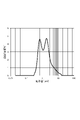
- 1 is a diagram showing measurement results of particle size distribution in Example 1.
- FIG. 3 is a diagram showing measurement results of particle size distribution of Comparative Example 1.
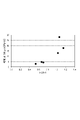
- FIG. 4 is a graph showing the relationship between H2/H1 and slurry viscosity in each example and each comparative example. It is a graph which shows the relationship between S2/S1 of each Example and each comparative example, and the viscosity of a slurry.
- the silicon nitride powder according to this embodiment contains primary particles of silicon nitride.
- aggregated particles in which the primary particles are aggregated may be included.
- the primary particles and aggregated particles may also have oxides such as silicon dioxide on their surfaces.
- the purity of silicon nitride in the silicon nitride powder may be 98% by mass or higher, or may be 99% by mass or higher.
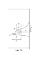
- FIG. 1 is a diagram showing an example of volume-based particle size distribution of silicon nitride powder measured with a particle size distribution measuring device using a laser diffraction/scattering method.
- the horizontal axis is the particle size [ ⁇ m] on a logarithmic scale, and the vertical axis is the frequency [% by volume].
- the particle size distribution in the present disclosure is measured according to the method described in JIS Z 8825:2013 "Particle Size Analysis-Laser Diffraction/Scattering Method”. Ultrasonic dispersion is performed as a pretreatment for measurement. Specifically, 60 mg of silicon nitride powder is weighed into a 500 mL container.
- a 20% aqueous solution of sodium hexametaphosphate (20 mL) and water (200 g) are added as a dispersant to obtain a measurement sample.
- the container containing the measurement sample is set in an ultrasonic dispersion machine manufactured by Sharp Corporation, and ultrasonically dispersed for 1 minute. Particle size distribution measurement is performed using the dispersion liquid obtained by such pretreatment.
- LS-13 320 (trade name) manufactured by Beckman Coulter is used for particle size distribution measurement.
- the particle refractive index is 2.2 and the solvent refractive index is 1.33.
- the particle size distribution measured under the above conditions has a first peak 10 and a second peak 20 in a particle size region larger than the first peak 10.
- a first peak 10 indicates the particle size of the primary particles of silicon nitride.
- the particle diameter d1 of the first peak 10 may be 0.2-1.0 ⁇ m.
- the lower limit of the particle diameter d1 may be 0.3 ⁇ m, 0.4 ⁇ m, or 0.5 ⁇ m from the viewpoint of ease of production.
- the upper limit of the particle diameter d1 may be 0.9 ⁇ m, 0.8 ⁇ m, or 0.7 ⁇ m from the viewpoint of improving sinterability.
- the second peak 20 indicates the particle size of the primary particles and aggregated particles formed by aggregating the primary particles.
- the particle size d2 of the second peak 20 may be greater than 1.5 ⁇ m and less than 4.0 ⁇ m.
- the lower limit of the particle diameter d2 may be 1.6 ⁇ m, 1.7 ⁇ m, or 1.8 ⁇ m from the viewpoint of improving sinterability.
- the upper limit of the particle diameter d2 may be 3.5 ⁇ m, 3.0 ⁇ m, or 2.5 ⁇ m from the viewpoint of improving sinterability.
- the particle diameter d3 of the valley bottom 30 between the first peak 10 and the second peak 20 may be greater than 1.0 ⁇ m and less than or equal to 1.5 ⁇ m.
- the particle diameter d3 may be between 1.1 ⁇ m and 1.3 ⁇ m.
- the height from the baseline of the valley bottom 30 between the first peak 10 and the second peak 20 is the minimum height H3.
- the particle size range of the first peak 10 and the second peak 20 including the particle size d3 includes the particle size at which the detector of the particle size distribution measuring device (manufactured by Beckman Coulter, trade name: LS-13 320) is switched. . Therefore, the boundaries between primary particles and aggregated particles can be made sufficiently clear.
- the particle diameter d3 may be the particle diameter at which the detector switches.
- H2/H1 When the heights of the first peak and the second peak based on the lowest height H3 are H1 and H2, respectively, H2/H1 may be 1.04 or less. In this way, by setting the ratio between the height H1 of the first peak and the height H2 of the second peak based on the minimum height H3 to a predetermined value or less, the influence of the overlapping distributions centered on each peak is reduced, and the proportion of agglomerated particles can be made sufficiently low. Therefore, it is possible to obtain a silicon nitride powder in which agglomeration of primary particles of silicon nitride is sufficiently suppressed. From the viewpoint of further reducing aggregated particles, H2/H1 may be 1.00 or less, 0.80 or less, or 0.71 or less.
- the lower limit of H2/H1 may be 0.1 or 0.3 from the viewpoint of ease of preparation.
- H2/H1 can be adjusted, for example, by the pulverization conditions in the pulverization step and the classification conditions in the classification step when manufacturing the silicon nitride powder.
- the minimum height H3 based on the baseline may be 0.1 to 6.0% by volume, or may be 1.0 to 5.0% by volume.
- the height H1 of the first peak based on the minimum height H3 may be 1.0 to 6.0% by volume, and may be 1.5 to 5.0% by volume.
- the height H2 of the second peak based on the lowest height H3 may be 0.5-4.0% by volume, and may be 0.8-3.0% by volume.
- S2/S1 When the areas of the first peak and the second peak based on the minimum height H3 are S1 and S2, respectively, S2/S1 may be 3.00 or less. In this way, by setting the ratio of the area S1 of the first peak and the area S2 of the second peak based on the minimum height H3 to a predetermined value or less, the influence of overlapping distributions centered on each peak is reduced. and the proportion of agglomerated particles can be sufficiently low. Therefore, it is possible to obtain a silicon nitride powder in which agglomeration of primary particles of silicon nitride is sufficiently suppressed. From the viewpoint of further reducing aggregated particles, S2/S1 may be 2.00 or less, 1.95 or less, or 1.90 or less.
- the lower limit of S2/S1 may be 0.1 or 0.3.
- S2/S1 can be adjusted by, for example, the pulverization conditions in the pulverization step and the classification conditions in the classification step when manufacturing the silicon nitride powder.
- the area S1 of the first peak and the area S2 of the second peak are areas above a straight line (broken line L1 in FIG. 1) that passes through the lowest height H3 and is parallel to the horizontal axis.
- the ratio of the area S1 of the first peak based on the minimum height H3 may be 0.3 to 2.0 [ ⁇ m vol%], and 0.4 to 1.5 [ ⁇ m vol%]. There may be.
- the ratio of the area S2 of the second peak based on the minimum height H3 may be 0.3 to 3.0 [ ⁇ m/volume%], and 0.4 to 1.6 [ ⁇ m/volume%]. There may be.
- the ratio of area S1 and the ratio of area S2 are calculated based on the area of the entire particle size distribution.
- the average particle size (D50, median size) of the silicon nitride powder obtained from the particle size distribution may be 0.8 to 1.8 ⁇ m. If such a silicon nitride powder is used as a raw material for a silicon nitride sintered body, the thermal conductivity and mechanical properties of the silicon nitride sintered body can be further improved. From the same point of view, the average particle size may be 1.0 to 1.6 ⁇ m, or 1.1 to 1.5 ⁇ m.
- the upper limit of the BET specific surface area of the silicon nitride powder may be, for example, 5.0 to 9.0 m 2 /g, 6.0 to 8.0 m 2 /g, 6.4 to 7.0 m 2 /g. It may be 5 m 2 /g.
- the BET specific surface area of the silicon nitride powder may be adjusted, for example, by changing the grinding conditions or the like during production of the silicon nitride powder.
- the BET specific surface area in the present disclosure conforms to the method described in JIS Z 8830:2013 "Method for measuring specific surface area of powder (solid) by gas adsorption" and is a value measured by the BET single-point method using nitrogen gas. is.
- the surface oxygen content of the silicon nitride powder may be 3.0% by mass or less, 2.5% by mass or less, or 2.2% by mass or less. When the surface oxygen content of the silicon nitride powder is within the above range, the grain boundary phase can be sufficiently reduced when the silicon nitride sintered body is produced.
- the surface oxygen content of the silicon nitride powder may be 0.2% by mass or more, or may be 0.5% by mass or more. When the surface oxygen content of the silicon nitride powder is within the above range, grain growth can be promoted when the silicon nitride powder is fired.
- the "surface oxygen content" in the present disclosure is obtained by the following procedure.
- a commercially available oxygen/nitrogen analyzer is used for the measurement.
- the measurement procedure is as follows. A sample for measurement is heated from 20° C. to 2000° C. at a heating rate of 8° C./second in a helium gas atmosphere. Oxygen desorbed with temperature rise is detected by an infrared absorption method. At the beginning of the temperature rise, oxygen bound to the surface of the silicon nitride powder is desorbed. When it is further heated and the temperature reaches around 1400° C., the silicon nitride begins to decompose. Nitrogen is detected when the silicon nitride decomposes. After this, oxygen inside the silicon nitride powder is desorbed. Therefore, the amount of oxygen detected after nitrogen starts to be detected corresponds to the amount of internal oxygen. Therefore, the amount of oxygen detected and quantified before nitrogen begins to be detected is the amount of surface oxygen in the present disclosure.
- the moisture content of the silicon nitride powder measured at 120°C may be 0.4% by mass or less, 0.3% by mass or less, or 0.2% by mass or less. By lowering the moisture content of the silicon nitride powder measured at 120° C., aggregation of the primary particles of silicon nitride can be suppressed.
- the moisture content of the silicon nitride powder may be 0.05% by mass or more, or may be 0.1% by mass or more, from the viewpoint of ease of production.
- the moisture content of the silicon nitride powder measured at 500°C may be 0.5% by mass or less, 0.4% by mass or less, or 0.3% by mass or less.
- a silicon nitride powder having such a low moisture content as measured at 500° C. has a high degree of purity. Therefore, for example, the thermal conductivity and mechanical properties of a silicon nitride sintered body can be further increased.
- Moisture content measured at 120°C moisture content 1
- Moisture content measured at 500°C moisture content 2
- Moisture content 1 is determined by weighing an empty weighing bottle, adding 5 g of a silicon nitride powder sample, and measuring the total weight of the weighing bottle and the sample. This is dried for 3 hours in a dryer set at 120°C. After drying, place the weighing bottle in a desiccator and cool. Then weigh and divide the weight loss of the sample by the initial weight of the sample. This value is the moisture content of 1.
- the moisture content 2 is measured using a Karl Fischer moisture meter.
- a Karl Fischer moisture meter As for the measurement method, an empty sample board is set in the combustion tube and the temperature is raised to 500° C. to perform blank measurement. A sample of silicon nitride powder of 0.9 to 1.0 g is then weighed onto the sample board of the apparatus and set in the combustion tube. The temperature is raised to 500° C. and the water content is analyzed and divided by the initial weight. This value is the moisture content of 2.
- the viscosity (30 rpm) at 25° C. of the slurry obtained by mixing the silicon nitride powder and water at a mass ratio of 1:1 may be 15 Pa s or less, and may be 10 Pa s or less. 0 Pa ⁇ s or less, or 5.0 Pa ⁇ s or less.
- a slurry having such a low viscosity is excellent in dispersibility of the silicon nitride powder, which is a solid content. Therefore, when the silicon nitride sintered body is produced by the wet molding process, it is possible to sufficiently reduce variations in the properties of the silicon nitride sintered body. Therefore, a silicon nitride sintered body having high thermal conductivity and mechanical properties can be stably produced.
- the viscosity (60 rpm) at 25° C. of the slurry obtained by mixing the silicon nitride powder and water at a mass ratio of 1:1 may be 9.0 Pa s or less, and 8.0 Pa • s or less, 6.0 Pa ⁇ s or less, or 3.0 Pa ⁇ s or less.
- the viscosity (30 rpm) of the slurry at 25°C may be 1.0 Pa ⁇ s or more, or may be 2.0 Pa ⁇ s or more.
- the viscosity (60 rpm) of the slurry at 25° C. may be 0.5 Pa ⁇ s or more, or may be 1.0 Pa ⁇ s or more.
- the viscosity of the slurry changes depending on the aggregation state of the primary particles of silicon nitride. That is, the silicon nitride powder in which the primary particles of silicon nitride are suppressed from agglomerating can reduce the viscosity of the slurry. Therefore, by using a silicon nitride powder capable of reducing the viscosity of the slurry, it is possible to sufficiently reduce the variation in the properties of the silicon nitride sintered body even in the dry molding process. Therefore, any process can stably produce a silicon nitride sintered body having high thermal conductivity and mechanical properties.
- Slurry viscosity in the present disclosure is measured by the following procedure. Water and silicon nitride powder are blended at a mass ratio of 1:1, and stirred manually until the powder does not settle at the bottom of the container. This disperses the silicon nitride powder in the water.
- the viscosity of the prepared slurry is measured using a commercially available B-type viscometer. The viscosity is measured at 25° C. and at a predetermined rotation speed (30 rpm, 60 rpm, etc.). As the B-type viscometer, TVB-10 (trade name) manufactured by Toki Sangyo Co., Ltd. can be used.
- the method for producing a silicon nitride powder of this example includes a firing step of firing a silicon powder in an atmosphere containing nitrogen and at least one selected from the group consisting of hydrogen and ammonia to obtain a fired product; It has a pulverization step of dry-pulverizing a material to obtain a pulverized material, and a classification step of dry-classifying the pulverized material.
- silicon powder with a low oxygen concentration may be used.
- the oxygen concentration of the silicon powder may be, for example, 0.40% by mass or less, 0.30% by mass or less, or 0.20% by mass or less.
- the lower limit of the oxygen concentration of the silicon powder may be, for example, 0.10% by mass or 0.15% by mass.
- the silicon powder may have an oxygen concentration of, for example, 0.10 to 0.40% by mass. Incidentally, the oxygen concentration of the silicon powder can be measured by an infrared absorption method.
- silicon powder may be used, or one prepared by a reaction may be used.
- a pretreatment liquid containing hydrofluoric acid can be used to reduce the amount of oxygen bound to the silicon powder.
- the silicon powder may be pretreated with a pretreatment liquid containing hydrofluoric acid to obtain a silicon powder having an oxygen concentration of 0.4% by mass.
- the pretreatment liquid may contain hydrofluoric acid.
- the pretreatment liquid may be, for example, a mixed acid with an acid such as hydrochloric acid, or may consist of only hydrofluoric acid.
- the temperature of the pretreatment liquid in the pretreatment step may be, for example, 40 to 80°C.
- the contact time between the pretreatment liquid and the silicon powder may be, for example, 1 to 10 hours.
- the silicon powder is fired in a mixed atmosphere containing nitrogen and at least one selected from the group consisting of hydrogen and ammonia to obtain a fired product containing silicon nitride.
- the total content of hydrogen and ammonia in the mixed atmosphere may be, for example, 10-40% by volume based on the entire mixed atmosphere.
- the firing temperature may be, for example, 1100-1450°C, or 1200-1400°C.
- the firing time may be, for example, 30-100 hours.
- the fired product obtained in the firing step is dry-pulverized to obtain a pulverized product.
- the pulverization process may be divided into multiple stages such as coarse pulverization and fine pulverization.
- the milling process may include two stages, a ball milling process and a vibratory milling process.
- the filling rate of balls in the container in the ball milling process may be 30 to 70% by volume.
- the lower limit of the ball filling rate in the container may be, for example, 50% by volume or 60% by volume based on the volume of the container.
- the upper limit of the ball filling rate in the container may be, for example, 65% by volume based on the volume of the container.
- the grinding treatment time (grinding time) in the ball mill grinding step may be 5 to 15 hours, or may be 8 to 12 hours. As a result, the aggregated particles can be made sufficiently fine while suppressing excessive pulverization.
- the pulverized product obtained in the ball mill pulverization step may be further pulverized by the vibration mill pulverization step.
- the filling rate of the balls in the container in the vibratory milling process may be 50 to 80% by volume, or may be 60 to 75% by volume.
- the grinding treatment time (grinding time) in the vibration mill grinding step may be 8 to 20 hours, or may be 12 to 17 hours.
- the pulverized material obtained in the pulverization step is dry-classified to obtain a silicon nitride powder having a desired particle size distribution.
- a silicon nitride powder having a desired particle size distribution.
- at least some of the agglomerated particles can be excluded to adjust the particle size distribution of the silicon nitride powder.
- Dry classification can be performed by air classification or the like.
- the airflow classifier can be classified by using a whirling airflow type using secondary air. As such an air classifier, for example, DS-10 (trade name) manufactured by Nippon Pneumatic Industry Co., Ltd. may be used.
- the primary air pressure (inlet pressure) may be, for example, 0.2-0.8 MPa, or 0.3-0.7 MPa.
- the primary air volume may be 1-4 m 3 /min, or 2-3 m 3 /min.
- the clearance of the secondary air intake may be 25-45 mm, and may be 30-40 mm.
- the mixing ratio (powder/air amount) will decrease, and the ratio of aggregated particles on the fine powder side can be reduced. That is, it is possible to reduce the proportion of agglomerated particles contained in the silicon nitride powder recovered as fine powder. If the amount of air is reduced by reducing the clearance of the secondary air intake port within the above range, the mixing ratio (powder/air amount) will be reduced and the proportion of aggregated particles on the fine powder side will be increased. That is, the proportion of aggregated particles contained in the silicon nitride powder recovered as fine powder increases.
- the ratio of the silicon nitride powder after classification (after removal of coarse particles) to the total amount of pulverized powder before the classification step may be 40 to 60% by mass, and may be 45 to 55% by mass. If this ratio is lowered, the content of aggregated particles can be further lowered. That is, the peak height ratio (H2/H1) and the peak area ratio (S2/S1) can be further reduced. On the other hand, if the above ratio is increased, the manufacturing cost of the silicon nitride powder can be reduced.
- the silicon nitride powder of the present embodiment can be produced through the above steps.
- the manufacturing method described above is an example, and is not limited to this.
- the silicon nitride powder of the present embodiment has reduced agglomerated particles, and is therefore excellent in sinterability. Therefore, silicon nitride powder may be used as a raw material for sintering.
- An embodiment of the method for producing a silicon nitride sintered body has a step of molding and firing the sintering raw material containing the silicon nitride powder described above.
- the raw material for sintering may contain an oxide-based sintering aid in addition to the silicon nitride powder.
- oxide-based sintering aids include Y 2 O 3 , MgO and Al 2 O 3 .
- the content of the oxide-based sintering aid in the raw material for sintering may be, for example, 3 to 10% by mass.
- the above sintering raw material is pressed with a molding pressure of, for example, 3.0 to 30 MPa to obtain a compact.
- the compact may be produced by uniaxial pressing or may be produced by CIP. Moreover, you may bake while shape
- the firing temperature may be 1860-2100°C, or 1880-2000°C.
- the firing time at the firing temperature may be 6 to 20 hours, or 8 to 16 hours.
- the heating rate to the firing temperature may be, for example, 1.0 to 10.0° C./hour.
- the obtained silicon nitride sintered body has reduced coarse grains and has a fine structure with excellent uniformity. Moreover, since it has a sufficiently dense structure, it is excellent in thermal conductivity and mechanical properties. In addition, since variation in particle size is reduced, variation in properties of the silicon nitride sintered body can be reduced.
- Example 1 ⁇ Preparation of Silicon Nitride Powder> A compact (bulk density: 1.4 g/cm 3 ) was produced using silicon powder. The obtained compact was placed in an electric furnace and fired at 1400° C. for 60 hours to produce a fired body containing silicon nitride. A mixed gas of nitrogen and hydrogen (a mixed gas in which N 2 and H 2 are mixed in a volume ratio of 80:20 in a standard state) was supplied as an atmosphere during firing. After roughly pulverizing the obtained sintered body, it was dry-pulverized with a ball mill. In the pulverization by the ball mill, the filling rate of the balls in the container was set to 60% by volume, and the pulverization time was set to 8 hours. Furthermore, the dry-pulverized material was dry-pulverized by a vibrating mill, and the filling rate of the balls to the container was set to 70% by volume, and the pulverization time was set to 15 hours.
- a mixed gas of nitrogen and hydrogen a mixed gas in which N 2 and H 2
- the silicon nitride powder obtained by dry pulverization was classified using an air classifier (trade name: DS-10, manufactured by Nippon Pneumatic Industry Co., Ltd.). Classification conditions were as follows. Primary air pressure: 0.4 MPa Primary air volume: 2 m 3 /min Secondary air intake clearance: 30mm
- Coarse particles were removed from the silicon nitride powder by classification.
- the mass ratio of the silicon nitride powder after classification to the total mass of the silicon nitride powder before classification was 43% by mass.
- the classified silicon nitride powder means a silicon nitride powder obtained by removing coarse particles (aggregated particles). The same applies to the following examples and comparative examples.
- the silicon nitride powder thus obtained was evaluated as follows.
- the particle size distribution of the silicon nitride powder was measured by laser diffraction/scattering method. The measurement was performed according to the method described in JIS Z 8825:2013 "Particle size analysis-laser diffraction/scattering method". Particle size distribution was measured by weighing 60 mg of silicon nitride powder into a 500 mL container. To this, a 20% aqueous solution of sodium hexametaphosphate (2 mL) and water (200 g) were blended as dispersants. This container was set in an ultrasonic dispersion machine manufactured by Sharp Corporation so that the entire portion containing the dispersion liquid was immersed, and ultrasonic dispersion was performed for 1 minute. The above-described particle size distribution measurement was performed using the sample after ultrasonic dispersion. The measured particle size distribution was as shown in FIG.
- the first peak As shown in Figure 2, two peaks were detected in the particle size distribution.
- the smaller particle size is referred to as the first peak, and the larger particle size is referred to as the second peak.
- the particle diameter d3 of the valley bottom between the first peak and the second peak and the frequency at the particle diameter d3 were defined as the minimum height H3.
- the particle size d1 of the first peak and the particle size d2 of the second peak, and the heights of the first peak and the second peak (H1 and H2) based on this minimum height H3 are as shown in Table 1.
- rice field. That is, the height H1 of the first peak is a value calculated by subtracting the lowest height H3 (% by volume) from the frequency (% by volume) of the first peak.
- the height H2 of the second peak is a value calculated by subtracting the minimum height H3 (% by volume) from the frequency (% by volume) of the second peak.
- Table 1 shows the areas (S1 and S2) of the first peak and the second peak based on the minimum height H3 (% by volume).
- the ratio of height H2 to height H1 (H2/H1), the ratio of area S2 to area S1 (S2/S1), and the average particle size (D50, median size) of silicon nitride powder are as shown in Table 2. Met.
- the BET specific surface area was measured according to JIS Z 8803:2013 by the BET single-point method using nitrogen gas. The results were as shown in Table 2.
- the surface oxygen content was measured using an oxygen/nitrogen analyzer (manufactured by Horiba, Ltd., device name: EMGA-920). Specifically, the silicon nitride powder was heated from 20° C. to 2000° C. at a heating rate of 8° C./sec in a helium atmosphere, and the amount of oxygen was measured before nitrogen was detected. The results were as shown in Table 2.
- Example 2 A silicon nitride powder was prepared in the same manner as in Example 1, except that the classification conditions were changed as follows. The mass ratio of the silicon nitride powder after classification to the total mass of the silicon nitride powder before classification was 45% by mass. The same measurements as in Example 1 were performed on the obtained silicon nitride powder. The results were as shown in Tables 1, 2 and 3. Primary air pressure: 0.4 MPa Primary air volume: 2 m 3 /min Secondary air intake clearance: 35mm
- Example 3 A silicon nitride powder was prepared in the same manner as in Example 1, except that the classification conditions were changed as follows. The mass ratio of the silicon nitride powder after classification to the total mass of the silicon nitride powder before classification was 48% by mass. Each measurement was performed in the same manner as in Example 1 for the obtained silicon nitride powder. The results were as shown in Tables 1, 2 and 3. Primary air pressure: 0.4 MPa Primary air volume: 2 m 3 /min Secondary air intake clearance: 40mm
- Example 4 A silicon nitride powder was prepared in the same manner as in Example 1, except that the classification conditions were changed as follows. The mass ratio of the silicon nitride powder after classification to the total mass of the silicon nitride powder before classification was 50% by mass. Each measurement was performed in the same manner as in Example 1 for the obtained silicon nitride powder. The results were as shown in Tables 1, 2 and 3. Primary air pressure: 0.4 MPa Primary air volume: 2 m 3 /min Secondary air intake clearance: 45mm
- Example 1 A silicon nitride powder was prepared in the same manner as in Example 1, except that the classification conditions were changed as follows. The mass ratio of the silicon nitride powder after classification to the total mass of the silicon nitride powder before classification was 62% by mass. Each measurement was performed in the same manner as in Example 1 for the obtained silicon nitride powder. The results were as shown in Tables 1, 2 and 3. The measured particle size distribution was as shown in FIG. Primary air pressure: 0.4 MPa Primary air volume: 2 m 3 /min Secondary air intake clearance: 50mm
- Example 2 A silicon nitride powder was prepared in the same manner as in Example 1, except that the classification conditions were changed as follows. The mass ratio of the silicon nitride powder after classification to the total mass of the silicon nitride powder before classification was 65% by mass. Each measurement was performed in the same manner as in Example 1 for the obtained silicon nitride powder. The results were as shown in Tables 1, 2 and 3. Primary air pressure: 0.2 MPa Primary air volume: 1 m 3 /min Secondary air intake clearance: 50mm
- FIG. 4 is a graph showing the relationship between the height ratio (H1/H2) of the first peak and the second peak and the slurry viscosity in each example and each comparative example.
- FIG. 5 is a graph showing the relationship between the area ratio (S2/S1) of the first peak and the second peak in each example and each comparative example and the slurry viscosity.
- a low-viscosity slurry can be prepared using the silicon nitride powder of each example. By using such a silicon nitride powder, it is possible to produce a silicon nitride sintered body with sufficiently reduced variations in properties.
- a silicon nitride powder in which aggregation of primary particles of silicon nitride is sufficiently suppressed is provided. Further, by using such a silicon nitride powder, there is provided a method for producing a silicon nitride sintered body capable of reducing variations in properties.
Abstract
This silicon nitride powder contains primary particles of silicon nitride, wherein the particle diameter distribution by volume, measured with a particle diameter distribution measurement device that uses laser diffraction and scattering, has a first peak 10 and a second peak 20 which is in the particle diameter region above that of the first peak 10. Defining H1 and H2 respectively as the heights of the first peak 10 and the second peak 20 with reference to the minimum height H3 of frequencies between the first peak 10 and the second peak 20, H2/H1 is less than or equal to 1.04.
Description
本開示は、窒化ケイ素粉末、及び窒化ケイ素焼結体の製造方法に関する。
The present disclosure relates to silicon nitride powder and a method for producing a silicon nitride sintered body.
窒化ケイ素は、強度、硬度、靭性、耐熱性、耐食性、耐熱衝撃性等に優れた材料であることから、ダイカストマシン及び溶解炉等の各種産業用の部品、及び自動車部品等に利用されている。また、窒化ケイ素は、高温における機械的特性にも優れることから、高温強度、高温クリープ特性が求められるガスタービン部品に用いることが検討されている。
Silicon nitride is a material with excellent strength, hardness, toughness, heat resistance, corrosion resistance, thermal shock resistance, etc., so it is used for various industrial parts such as die casting machines and melting furnaces, and automobile parts. . In addition, since silicon nitride is excellent in mechanical properties at high temperatures, it is being studied for use in gas turbine components that require high-temperature strength and high-temperature creep properties.
窒化ケイ素焼結体には、熱伝導率及び機械的特性の更なる向上が求められている。例えば、特許文献1では、常温における熱伝導率が100~300W/(m・K)であり、常温における3点曲げ強度が600~1500MPaであることを特徴とする窒化珪素質焼結体が記載されている。
Silicon nitride sintered bodies are required to have further improvements in thermal conductivity and mechanical properties. For example, Patent Document 1 describes a silicon nitride sintered body characterized by having a thermal conductivity of 100 to 300 W/(m K) at room temperature and a three-point bending strength of 600 to 1500 MPa at room temperature. It is
熱伝導率及び機械的特性の向上には、窒化ケイ素焼結体の原料として、窒化ケイ素の一次粒子の凝集が低減された窒化ケイ素粉末を用いることが有効であると考えられる。そこで、本開示は、窒化ケイ素の一次粒子の凝集が十分に抑制されている窒化ケイ素粉末を提供する。また、本開示は、このような窒化ケイ素粉末を用いることによって、優れた性状を有する窒化ケイ素焼結体の製造方法を提供する。
In order to improve the thermal conductivity and mechanical properties, it is considered effective to use silicon nitride powder with reduced agglomeration of silicon nitride primary particles as the raw material for the silicon nitride sintered body. Therefore, the present disclosure provides a silicon nitride powder in which aggregation of primary particles of silicon nitride is sufficiently suppressed. The present disclosure also provides a method for producing a silicon nitride sintered body having excellent properties by using such silicon nitride powder.
本開示は、一つの側面において、窒化ケイ素の一次粒子を含み、レーザー回折・散乱法を用いた粒子径分布測定装置で測定される体積基準の粒子径分布が、第1ピークと、第1ピークよりも大きい粒子径領域に第2ピークとを有し、第1ピークと第2ピークとの間の頻度の最低高さを基準とする第1ピーク及び第2ピークの高さをそれぞれH1及びH2としたときに、H2/H1が1.04以下である、窒化ケイ素粉末を提供する。
In one aspect, the present disclosure includes primary particles of silicon nitride, and the volume-based particle size distribution measured with a particle size distribution measuring device using a laser diffraction/scattering method has a first peak and a first peak. The heights of the first peak and the second peak based on the lowest height of the frequency between the first peak and the second peak are H1 and H2, respectively. Provided is a silicon nitride powder in which H2/H1 is 1.04 or less when .
上記粒子径分布において、第1ピークよりも大きい粒子径領域にある第2ピークは、第1ピークで示される粒子径を有する一次粒子が凝集して構成される凝集粒子が窒化ケイ素粉末に含まれることを示している。上記窒化ケイ素粉末は、第1ピークの高さH1に対する第2ピークの高さH2の比が所定値以下であることから、窒化ケイ素粉末における凝集粒子の含有割合が低い。このため、窒化ケイ素の一次粒子の凝集が十分に抑制されている。このような窒化ケイ素粉末は、窒化ケイ素焼結体の原料として好適に用いることができる。
In the particle size distribution, the second peak in the particle size region larger than the first peak is composed of agglomerated primary particles having the particle size indicated by the first peak, and the silicon nitride powder contains aggregated particles. It is shown that. In the silicon nitride powder, the ratio of the height H2 of the second peak to the height H1 of the first peak is equal to or less than a predetermined value, so that the content of aggregated particles in the silicon nitride powder is low. Therefore, aggregation of the primary particles of silicon nitride is sufficiently suppressed. Such silicon nitride powder can be suitably used as a raw material for a silicon nitride sintered body.
上記最低高さを基準とする第1ピーク及び第2ピークの面積をそれぞれS1及びS2としたときに、S2/S1が3.00以下であってもよい。これによって、窒化ケイ素の一次粒子の凝集が一層抑制された窒化ケイ素粉末とすることができる。
S2/S1 may be 3.00 or less when the areas of the first peak and the second peak based on the minimum height are S1 and S2, respectively. This makes it possible to obtain a silicon nitride powder in which agglomeration of the primary particles of silicon nitride is further suppressed.
本開示は、一つの側面において、窒化ケイ素の一次粒子を含み、レーザー回折・散乱法を用いた粒子径分布測定装置で測定される体積基準の粒子径分布が、第1ピークと、第1ピークよりも大きい粒子径領域に第2ピークとを有し、第1ピークと第2ピークとの間の頻度の最低高さを基準とする第1ピーク及び第2ピークの面積をそれぞれS1及びS2としたときに、S2/S1が3.00以下である、窒化ケイ素粉末を提供する。
In one aspect, the present disclosure includes primary particles of silicon nitride, and the volume-based particle size distribution measured with a particle size distribution measuring device using a laser diffraction/scattering method has a first peak and a first peak. The areas of the first peak and the second peak based on the lowest height of the frequency between the first peak and the second peak, which have a second peak in a particle size region larger than S1 and S2, respectively Provided is a silicon nitride powder having S2/S1 of 3.00 or less when
上記粒子径分布において、第1ピークよりも大きい粒子径領域にある第2ピークは、第1ピークで示される粒子径を有する一次粒子が凝集して構成される凝集粒子が窒化ケイ素粉末に含まれることを示している。上記窒化ケイ素粉末は、第1ピークの面積S1に対する第2ピークの面積S2の比が所定値以下であることから、窒化ケイ素粉末における凝集粒子の含有割合が低い。このため、窒化ケイ素の一次粒子の凝集が十分に抑制されている。このような窒化ケイ素粉末は、窒化ケイ素焼結体の原料として好適に用いることができる。
In the particle size distribution, the second peak in the particle size region larger than the first peak is composed of agglomerated primary particles having the particle size indicated by the first peak, and the silicon nitride powder contains aggregated particles. It is shown that. In the silicon nitride powder, the ratio of the area S2 of the second peak to the area S1 of the first peak is equal to or less than a predetermined value, so that the silicon nitride powder has a low content of agglomerated particles. Therefore, aggregation of the primary particles of silicon nitride is sufficiently suppressed. Such silicon nitride powder can be suitably used as a raw material for a silicon nitride sintered body.
120℃で測定される窒化ケイ素粉末の水分率が0.4質量%以下であってよい。これによって、窒化ケイ素粒子が経時的に凝集することを十分に抑制することができる。
The moisture content of the silicon nitride powder measured at 120°C may be 0.4% by mass or less. This can sufficiently prevent the silicon nitride particles from aggregating over time.
上記粒子径分布における第1ピークの粒子径d1は0.2~1.0μmであってよい。また、第2ピークの粒子径d2は1.5μmを超え且つ4.0μm未満であってよい。このような窒化ケイ素粉末を窒化ケイ素焼結体の原料に用いると、窒化ケイ素焼結体の熱伝導率及び機械的特性を一層高水準にすることができる。
The particle size d1 of the first peak in the particle size distribution may be 0.2 to 1.0 μm. Also, the particle diameter d2 of the second peak may be more than 1.5 μm and less than 4.0 μm. When such a silicon nitride powder is used as a raw material for a silicon nitride sintered body, the thermal conductivity and mechanical properties of the silicon nitride sintered body can be made to a higher level.
窒化ケイ素粉末の平均粒子径は0.8~1.8μmであってよい。このような窒化ケイ素粉末を窒化ケイ素焼結体の原料に用いると、窒化ケイ素焼結体の熱伝導率及び機械的特性を一層高水準にすることができる。
The average particle size of the silicon nitride powder may be 0.8-1.8 μm. When such a silicon nitride powder is used as a raw material for a silicon nitride sintered body, the thermal conductivity and mechanical properties of the silicon nitride sintered body can be made to a higher level.
窒化ケイ素粉末の表面酸素量は3.0質量%以下であってよい。これによって、窒化ケイ素粉末に含まれる二酸化ケイ素等の酸化物の含有量が低くなり、水分を吸着し難くなる。これによって、長期間保管したときの一次粒子の凝集を十分に抑制することができる。
The surface oxygen content of the silicon nitride powder may be 3.0% by mass or less. This reduces the content of oxides such as silicon dioxide contained in the silicon nitride powder, making it difficult for the powder to adsorb moisture. This can sufficiently suppress aggregation of the primary particles during long-term storage.
水と1:1の質量比で混合して得られるスラリーの25℃における粘度(30rpm)が15Pa・s以下であってよい。このような窒化ケイ素粉末は、一次粒子の凝集が抑制されているため、窒化ケイ素焼結体を製造したときに十分に緻密化することができる。したがって、窒化ケイ素焼結体の熱伝導率及び機械的特性を一層高水準にすることができる。
The viscosity (30 rpm) at 25°C of the slurry obtained by mixing with water at a mass ratio of 1:1 may be 15 Pa·s or less. In such a silicon nitride powder, aggregation of primary particles is suppressed, so that it can be sufficiently densified when a silicon nitride sintered body is produced. Therefore, the silicon nitride sintered body can have a higher level of thermal conductivity and mechanical properties.
本開示は、一つの側面において、上述の窒化ケイ素粉末を含む焼結原料を用いて窒化ケイ素焼結体を得る工程を有する、窒化ケイ素焼結体の製造方法を提供する。この製造方法で得られる窒化ケイ素焼結体は、窒化ケイ素粒子の凝集が十分に抑制されている窒化ケイ素粉末を含む焼結原料を用いる。このため、窒化ケイ素焼結体の微細組織の均一性を向上することができる。これによって、熱伝導率及び機械的特性に優れるとともに、性状のばらつきが低減された窒化ケイ素焼結体を得ることができる。
In one aspect, the present disclosure provides a method for producing a silicon nitride sintered body, which has a step of obtaining a silicon nitride sintered body using the sintering raw material containing the silicon nitride powder described above. The silicon nitride sintered body obtained by this manufacturing method uses a sintering raw material containing silicon nitride powder in which aggregation of silicon nitride particles is sufficiently suppressed. Therefore, the uniformity of the microstructure of the silicon nitride sintered body can be improved. Thereby, it is possible to obtain a silicon nitride sintered body that is excellent in thermal conductivity and mechanical properties and has reduced variation in properties.
窒化ケイ素の一次粒子の凝集が十分に抑制されている窒化ケイ素粉末を提供することができる。また、このような窒化ケイ素粉末を用いることによって、優れた性状を有する窒化ケイ素焼結体の製造方法を提供することができる。
It is possible to provide a silicon nitride powder in which the aggregation of silicon nitride primary particles is sufficiently suppressed. Moreover, by using such a silicon nitride powder, it is possible to provide a method for producing a silicon nitride sintered body having excellent properties.
以下、本開示の一実施形態を説明する。ただし、以下の実施形態は、本開示を説明するための例示であり、本開示を以下の内容に限定する趣旨ではない。
An embodiment of the present disclosure will be described below. However, the following embodiments are examples for explaining the present disclosure, and are not intended to limit the present disclosure to the following contents.
本実施形態に係る窒化ケイ素粉末は、窒化ケイ素の一次粒子を含む。この他に、この一次粒子が凝集している凝集粒子を含んでよい。また、一次粒子及び凝集粒子は、表面に二酸化ケイ素等の酸化物を有していてよい。窒化ケイ素粉末における窒化ケイ素の純度は98質量%以上であってよく、99質量%以上であってもよい。
The silicon nitride powder according to this embodiment contains primary particles of silicon nitride. In addition, aggregated particles in which the primary particles are aggregated may be included. The primary particles and aggregated particles may also have oxides such as silicon dioxide on their surfaces. The purity of silicon nitride in the silicon nitride powder may be 98% by mass or higher, or may be 99% by mass or higher.
図1は、レーザー回折・散乱法を用いた粒子径分布測定装置で測定される窒化ケイ素粉末の体積基準の粒子径分布の一例を示す図である。横軸は、対数目盛の粒度[μm]であり、縦軸は頻度[体積%]である。本開示における粒子径分布は、JIS Z 8825:2013「粒子径解析-レーザー回折・散乱法」に記載の方法に準拠して測定される。測定の際、前処理として超音波分散を行う。具体的には、500mLの容器に60mgの窒化ケイ素粉末を計り取る。これに、分散剤としてヘキサメタリン酸ナトリウムの20%水溶液(20mL)と水(200g)を入れて測定試料を得る。この測定試料が入った容器を、シャープ株式会社製の超音波分散機にセットし、1分間の超音波分散を行う。このような前処理で得られた分散液を用いて、粒子径分布測定を行う。粒子径分布測定には、ベックマンコールター社製のLS-13 320(商品名)を用いる。測定条件としては、粒子屈折率を2.2、溶媒の屈折率を1.33とする。
FIG. 1 is a diagram showing an example of volume-based particle size distribution of silicon nitride powder measured with a particle size distribution measuring device using a laser diffraction/scattering method. The horizontal axis is the particle size [μm] on a logarithmic scale, and the vertical axis is the frequency [% by volume]. The particle size distribution in the present disclosure is measured according to the method described in JIS Z 8825:2013 "Particle Size Analysis-Laser Diffraction/Scattering Method". Ultrasonic dispersion is performed as a pretreatment for measurement. Specifically, 60 mg of silicon nitride powder is weighed into a 500 mL container. A 20% aqueous solution of sodium hexametaphosphate (20 mL) and water (200 g) are added as a dispersant to obtain a measurement sample. The container containing the measurement sample is set in an ultrasonic dispersion machine manufactured by Sharp Corporation, and ultrasonically dispersed for 1 minute. Particle size distribution measurement is performed using the dispersion liquid obtained by such pretreatment. LS-13 320 (trade name) manufactured by Beckman Coulter is used for particle size distribution measurement. As measurement conditions, the particle refractive index is 2.2 and the solvent refractive index is 1.33.
上述の条件で測定される粒子径分布は、第1ピーク10と、第1ピーク10よりも大きい粒子径領域に第2ピーク20とを有する。第1ピーク10は、窒化ケイ素の一次粒子の粒子径を示している。第1ピーク10の粒子径d1は、0.2~1.0μmであってよい。粒子径d1の下限は、製造の容易性の観点から、0.3μmであってよく、0.4μmであってよく、0.5μmであってもよい。粒子径d1の上限は、焼結性向上の観点から、0.9μmであってよく、0.8μmであってよく、0.7μmであってもよい。
The particle size distribution measured under the above conditions has a first peak 10 and a second peak 20 in a particle size region larger than the first peak 10. A first peak 10 indicates the particle size of the primary particles of silicon nitride. The particle diameter d1 of the first peak 10 may be 0.2-1.0 μm. The lower limit of the particle diameter d1 may be 0.3 μm, 0.4 μm, or 0.5 μm from the viewpoint of ease of production. The upper limit of the particle diameter d1 may be 0.9 μm, 0.8 μm, or 0.7 μm from the viewpoint of improving sinterability.
第2ピーク20は、一次粒子、及び一次粒子が凝集して構成される凝集粒子の粒子径を示している。第2ピーク20の粒子径d2は1.5μmを超え且つ4.0μm未満であってよい。粒子径d2の下限は、焼結性向上の観点から、1.6μmであってよく、1.7μmであってよく、1.8μmであってもよい。粒子径d2の上限は、焼結性向上の観点から、3.5μmであってよく、3.0μmであってよく、2.5μmであってもよい。
The second peak 20 indicates the particle size of the primary particles and aggregated particles formed by aggregating the primary particles. The particle size d2 of the second peak 20 may be greater than 1.5 μm and less than 4.0 μm. The lower limit of the particle diameter d2 may be 1.6 μm, 1.7 μm, or 1.8 μm from the viewpoint of improving sinterability. The upper limit of the particle diameter d2 may be 3.5 μm, 3.0 μm, or 2.5 μm from the viewpoint of improving sinterability.
第1ピーク10と第2ピーク20との間の谷底30の粒子径d3は、1.0μmを超え且つ1.5μm以下であってよい。粒子径d3は、1.1μm~1.3μmであってもよい。第1ピーク10と第2ピーク20との間における谷底30のベースラインからの高さが最低高さH3である。粒子径d3を含む第1ピーク10と第2ピーク20の粒子径範囲には、粒子径分布測定装置(ベックマンコールター社製、商品名:LS-13 320)の検出器が切り替わる粒子径が含まれる。したがって、一次粒子と凝集粒子の境界を十分明瞭にすることができる。すなわち、第1ピーク10と第2ピーク20との間の領域において検出器が切り替わる粒子径分布測定装置を用いることによって、一次粒子と凝集粒子の境界を十分明瞭にすることができる。粒子径d3は、検出器が切り替わる粒子径であってよい。
The particle diameter d3 of the valley bottom 30 between the first peak 10 and the second peak 20 may be greater than 1.0 μm and less than or equal to 1.5 μm. The particle diameter d3 may be between 1.1 μm and 1.3 μm. The height from the baseline of the valley bottom 30 between the first peak 10 and the second peak 20 is the minimum height H3. The particle size range of the first peak 10 and the second peak 20 including the particle size d3 includes the particle size at which the detector of the particle size distribution measuring device (manufactured by Beckman Coulter, trade name: LS-13 320) is switched. . Therefore, the boundaries between primary particles and aggregated particles can be made sufficiently clear. That is, by using a particle size distribution measuring device in which the detector is switched in the region between the first peak 10 and the second peak 20, the boundary between the primary particles and the aggregated particles can be sufficiently clarified. The particle diameter d3 may be the particle diameter at which the detector switches.
最低高さH3を基準とする第1ピーク及び第2ピークの高さをそれぞれH1及びH2としたときに、H2/H1が1.04以下であってよい。このように、最低高さH3を基準とする第1ピークの高さH1と第2ピークの高さH2の比を所定値以下にすることによって、各ピークを中心とする分布同士の重なりの影響が低減され、凝集粒子の割合を十分に低くすることができる。したがって、窒化ケイ素の一次粒子の凝集が十分に抑制されている窒化ケイ素粉末とすることができる。凝集粒子を一層低減する観点から、H2/H1は、1.00以下であってよく、0.80以下であってよく、0.71以下であってもよい。H2/H1の下限は、調製の容易性の観点から、0.1であってよく、0.3であってもよい。H2/H1は、例えば、窒化ケイ素粉末を製造する際の粉砕工程における粉砕条件、及び、分級工程における分級条件等によって調整することができる。
When the heights of the first peak and the second peak based on the lowest height H3 are H1 and H2, respectively, H2/H1 may be 1.04 or less. In this way, by setting the ratio between the height H1 of the first peak and the height H2 of the second peak based on the minimum height H3 to a predetermined value or less, the influence of the overlapping distributions centered on each peak is reduced, and the proportion of agglomerated particles can be made sufficiently low. Therefore, it is possible to obtain a silicon nitride powder in which agglomeration of primary particles of silicon nitride is sufficiently suppressed. From the viewpoint of further reducing aggregated particles, H2/H1 may be 1.00 or less, 0.80 or less, or 0.71 or less. The lower limit of H2/H1 may be 0.1 or 0.3 from the viewpoint of ease of preparation. H2/H1 can be adjusted, for example, by the pulverization conditions in the pulverization step and the classification conditions in the classification step when manufacturing the silicon nitride powder.
ベースラインを基準とする最低高さH3は、0.1~6.0体積%であってよく、1.0~5.0体積%であってもよい。最低高さH3を基準とする第1ピークの高さH1は、1.0~6.0体積%であってよく、1.5~5.0体積%であってもよい。最低高さH3を基準とする第2ピークの高さH2は、0.5~4.0体積%であってよく、0.8~3.0体積%であってもよい。
The minimum height H3 based on the baseline may be 0.1 to 6.0% by volume, or may be 1.0 to 5.0% by volume. The height H1 of the first peak based on the minimum height H3 may be 1.0 to 6.0% by volume, and may be 1.5 to 5.0% by volume. The height H2 of the second peak based on the lowest height H3 may be 0.5-4.0% by volume, and may be 0.8-3.0% by volume.
最低高さH3を基準とする第1ピーク及び第2ピークの面積をそれぞれS1及びS2としたときに、S2/S1は3.00以下であってもよい。このように、最低高さH3を基準とする第1ピークの面積S1と第2ピークの面積S2の比を所定値以下にすることによって、各ピークを中心とする分布同士の重なりの影響が低減され、凝集粒子の割合を十分に低くすることができる。したがって、窒化ケイ素の一次粒子の凝集が十分に抑制されている窒化ケイ素粉末とすることができる。凝集粒子を一層低減する観点から、S2/S1は、2.00以下であってよく、1.95以下であってよく、1.90以下であってもよい。S2/S1の下限は、調製の容易性の観点から、0.1であってよく、0.3であってもよい。S2/S1は、例えば、窒化ケイ素粉末を製造する際の粉砕工程における粉砕条件、及び、分級工程における分級条件等によって調整することができる。
When the areas of the first peak and the second peak based on the minimum height H3 are S1 and S2, respectively, S2/S1 may be 3.00 or less. In this way, by setting the ratio of the area S1 of the first peak and the area S2 of the second peak based on the minimum height H3 to a predetermined value or less, the influence of overlapping distributions centered on each peak is reduced. and the proportion of agglomerated particles can be sufficiently low. Therefore, it is possible to obtain a silicon nitride powder in which agglomeration of primary particles of silicon nitride is sufficiently suppressed. From the viewpoint of further reducing aggregated particles, S2/S1 may be 2.00 or less, 1.95 or less, or 1.90 or less. From the viewpoint of ease of preparation, the lower limit of S2/S1 may be 0.1 or 0.3. S2/S1 can be adjusted by, for example, the pulverization conditions in the pulverization step and the classification conditions in the classification step when manufacturing the silicon nitride powder.
第1ピークの面積S1及び第2ピークの面積S2は、最低高さH3を通り、横軸に平行な直線(図1中の破線L1)よりも上側の各面積である。最低高さH3を基準とする第1ピークの面積S1の割合は、0.3~2.0[μm・体積%]であってよく、0.4~1.5[μm・体積%]であってもよい。最低高さH3を基準とする第2ピークの面積S2の割合は、0.3~3.0[μm・体積%]であってよく、0.4~1.6[μm・体積%]であってもよい。本開示において、面積S1の割合及び面積S2の割合は、粒子径分布全体の面積を基準にして算出される。
The area S1 of the first peak and the area S2 of the second peak are areas above a straight line (broken line L1 in FIG. 1) that passes through the lowest height H3 and is parallel to the horizontal axis. The ratio of the area S1 of the first peak based on the minimum height H3 may be 0.3 to 2.0 [μm vol%], and 0.4 to 1.5 [μm vol%]. There may be. The ratio of the area S2 of the second peak based on the minimum height H3 may be 0.3 to 3.0 [μm/volume%], and 0.4 to 1.6 [μm/volume%]. There may be. In the present disclosure, the ratio of area S1 and the ratio of area S2 are calculated based on the area of the entire particle size distribution.
粒子径分布より求められる窒化ケイ素粉末の平均粒子径(D50、メディアン径)は、0.8~1.8μmであってよい。このような窒化ケイ素粉末を窒化ケイ素焼結体の原料として用いれば、窒化ケイ素焼結体の熱伝導率及び機械的特性を一層高水準にすることができる。同様の観点から、平均粒子径は1.0~1.6μmであってよく、1.1~1.5μmであってもよい。
The average particle size (D50, median size) of the silicon nitride powder obtained from the particle size distribution may be 0.8 to 1.8 μm. If such a silicon nitride powder is used as a raw material for a silicon nitride sintered body, the thermal conductivity and mechanical properties of the silicon nitride sintered body can be further improved. From the same point of view, the average particle size may be 1.0 to 1.6 μm, or 1.1 to 1.5 μm.
窒化ケイ素粉末のBET比表面積の上限値は、例えば、5.0~9.0m2/gであってよく、6.0~8.0m2/gであってよく、6.4~7.5m2/gであってもよい。窒化ケイ素粉末のBET比表面積は、例えば、窒化ケイ素粉末の製造時における粉砕条件等を変えることで調整してもよい。本開示におけるBET比表面積は、JIS Z 8830:2013「ガス吸着による粉体(固体)の比表面積測定方法」に記載の方法に準拠し、窒素ガスを使用してBET一点法によって測定される値である。
The upper limit of the BET specific surface area of the silicon nitride powder may be, for example, 5.0 to 9.0 m 2 /g, 6.0 to 8.0 m 2 /g, 6.4 to 7.0 m 2 /g. It may be 5 m 2 /g. The BET specific surface area of the silicon nitride powder may be adjusted, for example, by changing the grinding conditions or the like during production of the silicon nitride powder. The BET specific surface area in the present disclosure conforms to the method described in JIS Z 8830:2013 "Method for measuring specific surface area of powder (solid) by gas adsorption" and is a value measured by the BET single-point method using nitrogen gas. is.
窒化ケイ素粉末の表面酸素量は、3.0質量%以下であってよく、2.5質量%以下であってよく、2.2質量%以下であってもよい。窒化ケイ素粉末の表面酸素量が上記範囲内であると、窒化ケイ素焼結体を製造した際の粒界相をより十分に低減することができる。窒化ケイ素粉末の表面酸素量は、0.2質量%以上であってよく、0.5質量%以上であってもよい。窒化ケイ素粉末の表面酸素量が上記範囲内であると、窒化ケイ素粉末を焼成したときの粒成長を促進することができる。
The surface oxygen content of the silicon nitride powder may be 3.0% by mass or less, 2.5% by mass or less, or 2.2% by mass or less. When the surface oxygen content of the silicon nitride powder is within the above range, the grain boundary phase can be sufficiently reduced when the silicon nitride sintered body is produced. The surface oxygen content of the silicon nitride powder may be 0.2% by mass or more, or may be 0.5% by mass or more. When the surface oxygen content of the silicon nitride powder is within the above range, grain growth can be promoted when the silicon nitride powder is fired.
本開示における「表面酸素量」は以下の手順で求められる。測定には市販の酸素・窒素分析装置を用いる。測定手順は以下のとおりである。測定用の試料を、ヘリウムガスの雰囲気中、8℃/秒の昇温速度で20℃から2000℃まで昇温する。昇温に伴って脱離する酸素を赤外線吸収法によって検知する。昇温当初は、窒化ケイ素粉末の表面に結合している酸素が脱離する。更に加熱し、温度が1400℃近傍に到達すると、窒化ケイ素が分解し始める。窒化ケイ素が分解すると、窒素が検出される。これ以降、窒化ケイ素粉末の内部にある酸素が脱離する。このため、窒素が検出し始めてから検出される酸素は、内部酸素量に相当する。したがって、窒素が検出され始める前までに検出され、定量された酸素量が、本開示における表面酸素量となる。
The "surface oxygen content" in the present disclosure is obtained by the following procedure. A commercially available oxygen/nitrogen analyzer is used for the measurement. The measurement procedure is as follows. A sample for measurement is heated from 20° C. to 2000° C. at a heating rate of 8° C./second in a helium gas atmosphere. Oxygen desorbed with temperature rise is detected by an infrared absorption method. At the beginning of the temperature rise, oxygen bound to the surface of the silicon nitride powder is desorbed. When it is further heated and the temperature reaches around 1400° C., the silicon nitride begins to decompose. Nitrogen is detected when the silicon nitride decomposes. After this, oxygen inside the silicon nitride powder is desorbed. Therefore, the amount of oxygen detected after nitrogen starts to be detected corresponds to the amount of internal oxygen. Therefore, the amount of oxygen detected and quantified before nitrogen begins to be detected is the amount of surface oxygen in the present disclosure.
120℃で測定される窒化ケイ素粉末の水分率は、0.4質量%以下であってよく、0.3質量%以下であってよく、0.2質量%以下であってもよい。120℃で測定される窒化ケイ素粉末の水分率を低くすることによって、窒化ケイ素の一次粒子の凝集を抑制することができる。窒化ケイ素粉末の水分率は、製造の容易性の観点から、0.05質量%以上であってよく、0.1質量%以上であってもよい。
The moisture content of the silicon nitride powder measured at 120°C may be 0.4% by mass or less, 0.3% by mass or less, or 0.2% by mass or less. By lowering the moisture content of the silicon nitride powder measured at 120° C., aggregation of the primary particles of silicon nitride can be suppressed. The moisture content of the silicon nitride powder may be 0.05% by mass or more, or may be 0.1% by mass or more, from the viewpoint of ease of production.
500℃で測定される窒化ケイ素粉末の水分率は、0.5質量%以下であってよく、0.4質量%以下であってよく、0.3質量%以下であってもよい。このように500℃で測定される窒化ケイ素粉末の水分率が低い窒化ケイ素粉末は、高い純度を有する。このため、例えば窒化ケイ素焼結体を作製したときの熱伝導率及び機械的特性を一層高くすることができる。
The moisture content of the silicon nitride powder measured at 500°C may be 0.5% by mass or less, 0.4% by mass or less, or 0.3% by mass or less. A silicon nitride powder having such a low moisture content as measured at 500° C. has a high degree of purity. Therefore, for example, the thermal conductivity and mechanical properties of a silicon nitride sintered body can be further increased.
本開示における「120℃で測定される水分率(水分率1)」及び「500℃で測定される水分率(水分率2)」は、それぞれ以下の手順で求められる。水分率1は、空の秤量瓶を秤量した後、窒化ケイ素粉末のサンプルを5g投入して、秤量瓶とサンプルの合計重量を測定する。これを120℃に設定された乾燥機にて3時間乾燥する。乾燥後、秤量瓶ごとデシケーターに入れ、冷却する。その後、秤量して、サンプルの重量減少量をサンプルの初期重量で割る。この値が水分率1である。
"Moisture content measured at 120°C (moisture content 1)" and "moisture content measured at 500°C (moisture content 2)" in the present disclosure are obtained by the following procedures. Moisture content 1 is determined by weighing an empty weighing bottle, adding 5 g of a silicon nitride powder sample, and measuring the total weight of the weighing bottle and the sample. This is dried for 3 hours in a dryer set at 120°C. After drying, place the weighing bottle in a desiccator and cool. Then weigh and divide the weight loss of the sample by the initial weight of the sample. This value is the moisture content of 1.
水分率2は、カール・フィッシャー水分計を用いて測定する。測定方法としては空の試料ボードを燃焼管にセットして500℃まで昇温を行ない、ブランク測定を行う。その後、窒化ケイ素粉末のサンプルを装置の試料ボードに0.9~1.0g計り取り、燃焼管にセットする。500℃まで昇温を行なって水分量を分析し、初期重量で割る。この値が水分率2である。
The moisture content 2 is measured using a Karl Fischer moisture meter. As for the measurement method, an empty sample board is set in the combustion tube and the temperature is raised to 500° C. to perform blank measurement. A sample of silicon nitride powder of 0.9 to 1.0 g is then weighed onto the sample board of the apparatus and set in the combustion tube. The temperature is raised to 500° C. and the water content is analyzed and divided by the initial weight. This value is the moisture content of 2.
窒化ケイ素粉末と水とを、1:1の質量比で混合して得られるスラリーの25℃における粘度(30rpm)は、15Pa・s以下であってよく、10Pa・s以下であってよく、8.0Pa・s以下であってよく、5.0Pa・s以下であってもよい。このように低い粘度を有するスラリーは、固形分である窒化ケイ素粉末の分散性に優れる。このため、湿式成形プロセスで窒化ケイ素焼結体を製造したときに、窒化ケイ素焼結体の性状のばらつきを十分に低減することができる。したがって、高い熱伝導率及び機械的特性を有する窒化ケイ素焼結体を安定的に製造することができる。
The viscosity (30 rpm) at 25° C. of the slurry obtained by mixing the silicon nitride powder and water at a mass ratio of 1:1 may be 15 Pa s or less, and may be 10 Pa s or less. 0 Pa·s or less, or 5.0 Pa·s or less. A slurry having such a low viscosity is excellent in dispersibility of the silicon nitride powder, which is a solid content. Therefore, when the silicon nitride sintered body is produced by the wet molding process, it is possible to sufficiently reduce variations in the properties of the silicon nitride sintered body. Therefore, a silicon nitride sintered body having high thermal conductivity and mechanical properties can be stably produced.
同様の理由により、窒化ケイ素粉末と水とを、1:1の質量比で混合して得られるスラリーの25℃における粘度(60rpm)は、9.0Pa・s以下であってよく、8.0Pa・s以下であってよく、6.0Pa・s以下であってよく、3.0Pa・s以下であってもよい。
For the same reason, the viscosity (60 rpm) at 25° C. of the slurry obtained by mixing the silicon nitride powder and water at a mass ratio of 1:1 may be 9.0 Pa s or less, and 8.0 Pa • s or less, 6.0 Pa·s or less, or 3.0 Pa·s or less.
製造コスト低減の観点から、上記スラリーの25℃における粘度(30rpm)は、1.0Pa・s以上であってよく、2.0Pa・s以上であってもよい。同様の観点から、上記スラリーの25℃における粘度(60rpm)は、0.5Pa・s以上であってよく、1.0Pa・s以上であってもよい。
From the viewpoint of manufacturing cost reduction, the viscosity (30 rpm) of the slurry at 25°C may be 1.0 Pa·s or more, or may be 2.0 Pa·s or more. From a similar point of view, the viscosity (60 rpm) of the slurry at 25° C. may be 0.5 Pa·s or more, or may be 1.0 Pa·s or more.
スラリーの粘度は、窒化ケイ素の一次粒子の凝集状態によって変化する。すなわち、窒化ケイ素の一次粒子の凝集が抑制された窒化ケイ素粉末であれば、スラリーの粘度を低くすることができる。したがって、スラリーの粘度を低くすることが可能な窒化ケイ素粉末を用いれば、乾式成形プロセスであっても、窒化ケイ素焼結体の性状のばらつきを十分に低減することができる。したがって、いずれのプロセスであっても、高い熱伝導率及び機械的特性を有する窒化ケイ素焼結体を安定的に製造することができる。
The viscosity of the slurry changes depending on the aggregation state of the primary particles of silicon nitride. That is, the silicon nitride powder in which the primary particles of silicon nitride are suppressed from agglomerating can reduce the viscosity of the slurry. Therefore, by using a silicon nitride powder capable of reducing the viscosity of the slurry, it is possible to sufficiently reduce the variation in the properties of the silicon nitride sintered body even in the dry molding process. Therefore, any process can stably produce a silicon nitride sintered body having high thermal conductivity and mechanical properties.
本開示における「スラリーの粘度」は、以下の手順で測定される。水と窒化ケイ素粉末とを1:1の質量比で配合し、容器下部に粉末が沈殿しない状態になるまで手動で撹拌する。これによって、水中に窒化ケイ素粉末を分散させる。調製したスラリーの粘度を、市販のB型粘度計を用いて測定する。粘度の測定は、25℃において、所定の回転速度(30rpm、及び60rpm等)で行う。B型粘度計としては、東機産業株式会社製のTVB-10(商品名)を用いることができる。
"Slurry viscosity" in the present disclosure is measured by the following procedure. Water and silicon nitride powder are blended at a mass ratio of 1:1, and stirred manually until the powder does not settle at the bottom of the container. This disperses the silicon nitride powder in the water. The viscosity of the prepared slurry is measured using a commercially available B-type viscometer. The viscosity is measured at 25° C. and at a predetermined rotation speed (30 rpm, 60 rpm, etc.). As the B-type viscometer, TVB-10 (trade name) manufactured by Toki Sangyo Co., Ltd. can be used.
上述の窒化ケイ素粉末の製造方法の一例を以下に説明する。本例の窒化ケイ素粉末の製造方法は、ケイ素粉末を、窒素と、水素及びアンモニアからなる群より選択される少なくとも一種と、を含む雰囲気下で焼成して焼成物を得る焼成工程と、上記焼成物を乾式粉砕して粉砕物を得る粉砕工程と、上記粉砕物を乾式分級する分級工程と、を有する。
An example of the method for producing the silicon nitride powder described above will be described below. The method for producing a silicon nitride powder of this example includes a firing step of firing a silicon powder in an atmosphere containing nitrogen and at least one selected from the group consisting of hydrogen and ammonia to obtain a fired product; It has a pulverization step of dry-pulverizing a material to obtain a pulverized material, and a classification step of dry-classifying the pulverized material.
ケイ素粉末としては、酸素濃度の低いケイ素粉末を用いてもよい。ケイ素粉末の酸素濃度は、例えば、0.40質量%以下であってよく、0.30質量%以下であってよく、0.20質量%以下であってもよい。ケイ素粉末の酸素濃度を上記範囲内とすることで、得られる窒化ケイ素粉末の内部における酸素量をより低減できる。ケイ素粉末の酸素濃度の下限値は、例えば、0.10質量%であってよく、0.15質量%であってもよい。ケイ素粉末の酸素濃度は、例えば、0.10~0.40質量%であってよい。なお、ケイ素粉末の酸素濃度は、赤外線吸収法によって測定することができる。
As the silicon powder, silicon powder with a low oxygen concentration may be used. The oxygen concentration of the silicon powder may be, for example, 0.40% by mass or less, 0.30% by mass or less, or 0.20% by mass or less. By setting the oxygen concentration of the silicon powder within the above range, the amount of oxygen inside the resulting silicon nitride powder can be further reduced. The lower limit of the oxygen concentration of the silicon powder may be, for example, 0.10% by mass or 0.15% by mass. The silicon powder may have an oxygen concentration of, for example, 0.10 to 0.40% by mass. Incidentally, the oxygen concentration of the silicon powder can be measured by an infrared absorption method.
ケイ素粉末は、市販の物を用いてよく、反応によって調製したものを用いてもよい。ケイ素粉末の酸素濃度が高い場合には、例えば、フッ化水素酸を含む前処理液を用いて、ケイ素粉末に結合する酸素量を低減することができる。この場合、フッ化水素酸を含む前処理液を用いてケイ素粉末を前処理し、酸素濃度が0.4質量%であるケイ素粉末を得る前処理工程を更に有していてもよい。
Commercially available silicon powder may be used, or one prepared by a reaction may be used. When the silicon powder has a high oxygen concentration, for example, a pretreatment liquid containing hydrofluoric acid can be used to reduce the amount of oxygen bound to the silicon powder. In this case, the silicon powder may be pretreated with a pretreatment liquid containing hydrofluoric acid to obtain a silicon powder having an oxygen concentration of 0.4% by mass.
前処理液は、フッ化水素酸を含んでよい。前処理液は、例えば、塩酸等の酸との混酸であってもよく、フッ化水素酸のみからなっていてもよい。前処理工程における前処理液の温度は、例えば、40~80℃であってよい。また、前処理液とケイ素粉末との接触時間は、例えば、1~10時間であってよい。
The pretreatment liquid may contain hydrofluoric acid. The pretreatment liquid may be, for example, a mixed acid with an acid such as hydrochloric acid, or may consist of only hydrofluoric acid. The temperature of the pretreatment liquid in the pretreatment step may be, for example, 40 to 80°C. Also, the contact time between the pretreatment liquid and the silicon powder may be, for example, 1 to 10 hours.
焼成工程では、ケイ素粉末を、窒素と、水素及びアンモニアからなる群より選択される少なくも一種と、を含む混合雰囲気下で焼成して窒化ケイ素を含む焼成物を得る。混合雰囲気における水素及びアンモニアの合計の含有量は、混合雰囲気全体を基準として、例えば、10~40体積%であってよい。焼成温度は、例えば、1100~1450℃であってよく、1200~1400℃であってもよい。焼成時間は、例えば、30~100時間であってよい。
In the firing step, the silicon powder is fired in a mixed atmosphere containing nitrogen and at least one selected from the group consisting of hydrogen and ammonia to obtain a fired product containing silicon nitride. The total content of hydrogen and ammonia in the mixed atmosphere may be, for example, 10-40% by volume based on the entire mixed atmosphere. The firing temperature may be, for example, 1100-1450°C, or 1200-1400°C. The firing time may be, for example, 30-100 hours.
粉砕工程では、焼成工程で得られた上記焼成物を乾式で粉砕して粉砕物を得る。粉砕工程は、粗粉砕と微粉砕というように複数段階に分けて行ってもよい。例えば、粉砕工程は、ボールミル粉砕工程及び振動ミル粉砕工程の2つの工程を含んでよい。焼成物を粉砕し、粒度を調整することによって、後の分級工程を円滑に行うことができる。
In the pulverization step, the fired product obtained in the firing step is dry-pulverized to obtain a pulverized product. The pulverization process may be divided into multiple stages such as coarse pulverization and fine pulverization. For example, the milling process may include two stages, a ball milling process and a vibratory milling process. By pulverizing the fired product and adjusting the particle size, the subsequent classification step can be performed smoothly.
ボールミル粉砕工程における容器へのボールの充填率は、30~70体積%であってよい。容器へのボールの充填率の下限は、容器の容積を基準として、例えば、50体積%であってよく、60体積%であってもよい。容器へのボールの充填率の上限は、容器の容積を基準として、例えば、65体積%であってもよい。
The filling rate of balls in the container in the ball milling process may be 30 to 70% by volume. The lower limit of the ball filling rate in the container may be, for example, 50% by volume or 60% by volume based on the volume of the container. The upper limit of the ball filling rate in the container may be, for example, 65% by volume based on the volume of the container.
ボールミル粉砕工程における粉砕処理の時間(粉砕時間)は、5~15時間であってよく、8~12時間であってもよい。これによって、過剰な粉砕を抑制しつつ、凝集粒子を十分に細かくすることができる。
The grinding treatment time (grinding time) in the ball mill grinding step may be 5 to 15 hours, or may be 8 to 12 hours. As a result, the aggregated particles can be made sufficiently fine while suppressing excessive pulverization.
ボールミル粉砕工程で得られた粉砕物を、振動ミル粉砕工程によってさらに粉砕してよい。振動ミル粉砕工程における容器へのボールの充填率は、50~80体積%であってよく、60~75体積%であってもよい。振動ミル粉砕工程における粉砕処理の時間(粉砕時間)は、8~20時間であってよく、12~17時間であってもよい。これによって、過剰な粉砕を抑制しつつ、凝集粒子を十分に細かくすることができる。また、分級工程の処理効率をより向上することができる。
The pulverized product obtained in the ball mill pulverization step may be further pulverized by the vibration mill pulverization step. The filling rate of the balls in the container in the vibratory milling process may be 50 to 80% by volume, or may be 60 to 75% by volume. The grinding treatment time (grinding time) in the vibration mill grinding step may be 8 to 20 hours, or may be 12 to 17 hours. As a result, the aggregated particles can be made sufficiently fine while suppressing excessive pulverization. Moreover, the processing efficiency of the classification step can be further improved.
分級工程では、粉砕工程によって得られた上記粉砕物を乾式で分級して、所望の粒子径分布を有する窒化ケイ素粉末を得る。例えば、凝集粒子の少なくとも一部を排除して窒化ケイ素粉末の粒子径分布を調整することができる。乾式分級は、気流分級等によって行うことができる。気流分級器は、二次空気を用いる旋回気流式のものを用いて分級することができる。このような気流分級器としては、例えば、日本ニューマチック工業株式会社製のDS-10(商品名)を用いてよい。
In the classification step, the pulverized material obtained in the pulverization step is dry-classified to obtain a silicon nitride powder having a desired particle size distribution. For example, at least some of the agglomerated particles can be excluded to adjust the particle size distribution of the silicon nitride powder. Dry classification can be performed by air classification or the like. The airflow classifier can be classified by using a whirling airflow type using secondary air. As such an air classifier, for example, DS-10 (trade name) manufactured by Nippon Pneumatic Industry Co., Ltd. may be used.
気流分級器の運転条件の一例は以下のとおりである。一次空気圧力(入口圧力)は、例えば、0.2~0.8MPaであってよく、0.3~0.7MPaであってもよい。一次空気量は、1~4m3/minであってよく、2~3m3/minであってもよい。二次空気取り込み口のクリアランスは、25~45mmであってよく、30~40mmであってもよい。このような条件で分級することによって、粉砕工程で十分に粉砕されない凝集粒子を、粗粒として高精度に除去することができる。
An example of operating conditions for the air classifier is as follows. The primary air pressure (inlet pressure) may be, for example, 0.2-0.8 MPa, or 0.3-0.7 MPa. The primary air volume may be 1-4 m 3 /min, or 2-3 m 3 /min. The clearance of the secondary air intake may be 25-45 mm, and may be 30-40 mm. By classifying under such conditions, aggregated particles that are not sufficiently pulverized in the pulverization step can be removed as coarse particles with high precision.
上述の範囲で、二次空気取り込み口のクリアランスを大きくして空気量を増やすと混合比(粉体/空気量)が小さくなって、微粉側の凝集粒子の比率を小さくすることができる。すなわち、微粉として回収される窒化ケイ素粉末に含まれる凝集粒子の割合を小さくすることができる。上述の範囲で、二次空気取り込み口のクリアランスを小さくして空気量を減らすと混合比(粉体/空気量)が小さくなって、微粉側の凝集粒子の比率を大きくなる。すなわち、微粉として回収される窒化ケイ素粉末に含まれる凝集粒子の割合が大きくなる。
Within the above range, if the clearance of the secondary air inlet is increased to increase the amount of air, the mixing ratio (powder/air amount) will decrease, and the ratio of aggregated particles on the fine powder side can be reduced. That is, it is possible to reduce the proportion of agglomerated particles contained in the silicon nitride powder recovered as fine powder. If the amount of air is reduced by reducing the clearance of the secondary air intake port within the above range, the mixing ratio (powder/air amount) will be reduced and the proportion of aggregated particles on the fine powder side will be increased. That is, the proportion of aggregated particles contained in the silicon nitride powder recovered as fine powder increases.
分級工程前の粉砕粉の全量に対する、分級後(粗粒除去後)の窒化ケイ素粉末の比率は、40~60質量%であってよく、45~55質量%であってよい。この比率を低くすれば、凝集粒子の含有割合を一層低くすることができる。すなわち、ピークの高さの比(H2/H1)及びピークの面積の比(S2/S1)を一層小さくすることができる。一方、上記比率を高くすれば、窒化ケイ素粉末の製造コストを低減できる。
The ratio of the silicon nitride powder after classification (after removal of coarse particles) to the total amount of pulverized powder before the classification step may be 40 to 60% by mass, and may be 45 to 55% by mass. If this ratio is lowered, the content of aggregated particles can be further lowered. That is, the peak height ratio (H2/H1) and the peak area ratio (S2/S1) can be further reduced. On the other hand, if the above ratio is increased, the manufacturing cost of the silicon nitride powder can be reduced.
以上の工程によって、本実施形態の窒化ケイ素粉末を製造することができる。ただし、上述の製造方法は一例であり、これに限定されない。本実施形態の窒化ケイ素粉末は、凝集粒子が低減されていることから、焼結性に優れる。このため、窒化ケイ素粉末は焼結原料に用いてもよい。
The silicon nitride powder of the present embodiment can be produced through the above steps. However, the manufacturing method described above is an example, and is not limited to this. The silicon nitride powder of the present embodiment has reduced agglomerated particles, and is therefore excellent in sinterability. Therefore, silicon nitride powder may be used as a raw material for sintering.
窒化ケイ素焼結体の製造方法の一実施形態は、上述の窒化ケイ素粉末を含む焼結原料を成形して焼成する工程を有する。
An embodiment of the method for producing a silicon nitride sintered body has a step of molding and firing the sintering raw material containing the silicon nitride powder described above.
焼結原料は、窒化ケイ素粉末の他に、酸化物系焼結助剤を含んでもよい。酸化物系焼結助剤としては、例えば、Y2O3、MgO及びAl2O3等が挙げられる。焼結原料における酸化物系焼結助剤の含有量は、例えば、3~10質量%であってよい。
The raw material for sintering may contain an oxide-based sintering aid in addition to the silicon nitride powder. Examples of oxide-based sintering aids include Y 2 O 3 , MgO and Al 2 O 3 . The content of the oxide-based sintering aid in the raw material for sintering may be, for example, 3 to 10% by mass.
上記工程では、上述の焼結原料を例えば3.0~30MPaの成形圧力で加圧して成形体を得る。成形体は一軸加圧して作製してもよいし、CIPによって作製してもよい。また、ホットプレスによって成形しながら焼成してもよい。成形体の焼成は、窒素ガス又はアルゴンガス等の不活性ガス雰囲気中で行ってよい。焼成時の圧力は、0.7~1MPaであってよい。焼成温度は1860~2100℃であってよく、1880~2000℃であってもよい。当該焼成温度における焼成時間は6~20時間であってよく、8~16時間であってよい。焼成温度までの昇温速度は、例えば1.0~10.0℃/時間であってよい。
In the above process, the above sintering raw material is pressed with a molding pressure of, for example, 3.0 to 30 MPa to obtain a compact. The compact may be produced by uniaxial pressing or may be produced by CIP. Moreover, you may bake while shape|molding by a hot press. Firing of the compact may be performed in an inert gas atmosphere such as nitrogen gas or argon gas. The pressure during firing may be 0.7 to 1 MPa. The firing temperature may be 1860-2100°C, or 1880-2000°C. The firing time at the firing temperature may be 6 to 20 hours, or 8 to 16 hours. The heating rate to the firing temperature may be, for example, 1.0 to 10.0° C./hour.
得られる窒化ケイ素焼結体は、粗粒が低減されており、均一性に優れる微細組織を有する。また、十分に緻密な組織を有するため、熱伝導率及び機械的特性に優れる。また、粒子の大きさの変動が低減されているため、窒化ケイ素焼結体の性状のばらつきを低減することができる。
The obtained silicon nitride sintered body has reduced coarse grains and has a fine structure with excellent uniformity. Moreover, since it has a sufficiently dense structure, it is excellent in thermal conductivity and mechanical properties. In addition, since variation in particle size is reduced, variation in properties of the silicon nitride sintered body can be reduced.
以上、幾つかの実施形態について説明したが、本開示は上記実施形態に何ら限定されるものではない。また、上述した各実施形態についての説明内容は、互いに適用することができる。
Although several embodiments have been described above, the present disclosure is not limited to the above embodiments. In addition, the contents of the description of each of the above-described embodiments can be applied to each other.
以下、実施例及び比較例を参照して本開示の内容をより詳細に説明する。ただし、本開示は、下記の実施例に限定されるものではない。
Hereinafter, the contents of the present disclosure will be described in more detail with reference to examples and comparative examples. However, the present disclosure is not limited to the following examples.
(実施例1)
<窒化ケイ素粉末の調製>
ケイ素粉末を用いて成形体(嵩密度:1.4g/cm3)を作製した。得られた成形体を電気炉内に静置し、1400℃で60時間焼成し、窒化ケイ素を含む焼成体を作製した。焼成時の雰囲気として、窒素と水素との混合ガス(N2とH2とを標準状態における体積比で80:20となるように混合した混合ガス)を供給した。得られた焼成体を粗粉砕した後、ボールミルで乾式粉砕した。ボールミルによる粉砕では、容器に対するボールの充填率を60体積%とし、粉砕時間を8時間とした。更に振動ミルにて乾式粉砕した、容器に対するボールの充填率を70体積%とし、粉砕時間を15時間とした。 (Example 1)
<Preparation of Silicon Nitride Powder>
A compact (bulk density: 1.4 g/cm 3 ) was produced using silicon powder. The obtained compact was placed in an electric furnace and fired at 1400° C. for 60 hours to produce a fired body containing silicon nitride. A mixed gas of nitrogen and hydrogen (a mixed gas in which N 2 and H 2 are mixed in a volume ratio of 80:20 in a standard state) was supplied as an atmosphere during firing. After roughly pulverizing the obtained sintered body, it was dry-pulverized with a ball mill. In the pulverization by the ball mill, the filling rate of the balls in the container was set to 60% by volume, and the pulverization time was set to 8 hours. Furthermore, the dry-pulverized material was dry-pulverized by a vibrating mill, and the filling rate of the balls to the container was set to 70% by volume, and the pulverization time was set to 15 hours.
乾式粉砕して得られた窒化ケイ素粉末を、気流分級器(日本ニューマチック工業株式会社製、商品名:DS-10)を用いて分級した。分級条件は、以下のとおりとした。
一次空気圧力:0.4MPa
一次空気量:2m3/min
二次空気取り込み口のクリアランス:30mm The silicon nitride powder obtained by dry pulverization was classified using an air classifier (trade name: DS-10, manufactured by Nippon Pneumatic Industry Co., Ltd.). Classification conditions were as follows.
Primary air pressure: 0.4 MPa
Primary air volume: 2 m 3 /min
Secondary air intake clearance: 30mm
分級によって、窒化ケイ素粉末から粗粒(凝集粒子)を除去した。分級前の窒化ケイ素粉末の全質量を基準とする、分級後の窒化ケイ素粉末の質量比率は、43質量%であった。この分級後の窒化ケイ素粉末とは、粗粒(凝集粒子)を除去して得られた窒化ケイ素粉末を意味する。以下の実施例及び比較例でも同様である。このようにして得られた窒化ケイ素粉末を、以下のとおり評価した。
Coarse particles (aggregated particles) were removed from the silicon nitride powder by classification. The mass ratio of the silicon nitride powder after classification to the total mass of the silicon nitride powder before classification was 43% by mass. The classified silicon nitride powder means a silicon nitride powder obtained by removing coarse particles (aggregated particles). The same applies to the following examples and comparative examples. The silicon nitride powder thus obtained was evaluated as follows.
<粒子径分布の測定>
レーザー回折・散乱法によって窒化ケイ素粉末の粒子径分布を測定した。測定は、JIS Z 8825:2013「粒子径解析-レーザー回折・散乱法」に記載の方法に準拠して行った。粒子径分布の測定は、500mLの容器に60mgの窒化ケイ素粉末を計り取った。これに、分散剤として、ヘキサメタリン酸ナトリウムの20%水溶液(2mL)と水(200g)を配合した。この容器を、シャープ株式会社製の超音波分散機に、分散液の収容部分が全て浸漬されるようにセットし、1分間の超音波分散を行った。超音波分散後の試料を用いて上述の粒子径分布測定を行った。測定した粒子径分布は、図2に示すとおりであった。 <Measurement of particle size distribution>
The particle size distribution of the silicon nitride powder was measured by laser diffraction/scattering method. The measurement was performed according to the method described in JIS Z 8825:2013 "Particle size analysis-laser diffraction/scattering method". Particle size distribution was measured by weighing 60 mg of silicon nitride powder into a 500 mL container. To this, a 20% aqueous solution of sodium hexametaphosphate (2 mL) and water (200 g) were blended as dispersants. This container was set in an ultrasonic dispersion machine manufactured by Sharp Corporation so that the entire portion containing the dispersion liquid was immersed, and ultrasonic dispersion was performed for 1 minute. The above-described particle size distribution measurement was performed using the sample after ultrasonic dispersion. The measured particle size distribution was as shown in FIG.
図2に示すとおり、粒子径分布では2つのピークが検出された。粒子径が小さい方を第1ピーク、及び、粒子径が大きい方を第2ピークと称する。第1ピークと第2ピークの間の谷底の粒子径d3と、粒子径d3における頻度を最低高さH3とした。第1ピークの粒子径d1及び第2ピークの粒子径d2と、この最低高さH3を基準とする第1ピーク及び第2ピークの高さ(H1及びH2)は、表1に示すとおりであった。すなわち、第1ピークの高さH1は、第1ピークの頻度(体積%)から、最低高さH3(体積%)を差し引いて算出される値である。第2ピークの高さH2は、第2ピークの頻度(体積%)から、最低高さH3(体積%)を差し引いて算出される値である。また、最低高さH3(体積%)を基準(底辺)とする第1ピーク及び第2ピークの面積(S1及びS2)は、表1に示すとおりであった。高さH1に対する高さH2の比(H2/H1)、面積S1に対する面積S2の比(S2/S1)、及び、窒化ケイ素粉末の平均粒子径(D50、メディアン径)は、表2に示すとおりであった。
As shown in Figure 2, two peaks were detected in the particle size distribution. The smaller particle size is referred to as the first peak, and the larger particle size is referred to as the second peak. The particle diameter d3 of the valley bottom between the first peak and the second peak and the frequency at the particle diameter d3 were defined as the minimum height H3. The particle size d1 of the first peak and the particle size d2 of the second peak, and the heights of the first peak and the second peak (H1 and H2) based on this minimum height H3 are as shown in Table 1. rice field. That is, the height H1 of the first peak is a value calculated by subtracting the lowest height H3 (% by volume) from the frequency (% by volume) of the first peak. The height H2 of the second peak is a value calculated by subtracting the minimum height H3 (% by volume) from the frequency (% by volume) of the second peak. Table 1 shows the areas (S1 and S2) of the first peak and the second peak based on the minimum height H3 (% by volume). The ratio of height H2 to height H1 (H2/H1), the ratio of area S2 to area S1 (S2/S1), and the average particle size (D50, median size) of silicon nitride powder are as shown in Table 2. Met.
<BET比表面積の測定>
BET比表面積は、JIS Z 8803:2013に準拠し、窒素ガスを使用してBET一点法により測定した。結果は表2に示すとおりであった。 <Measurement of BET specific surface area>
The BET specific surface area was measured according to JIS Z 8803:2013 by the BET single-point method using nitrogen gas. The results were as shown in Table 2.
BET比表面積は、JIS Z 8803:2013に準拠し、窒素ガスを使用してBET一点法により測定した。結果は表2に示すとおりであった。 <Measurement of BET specific surface area>
The BET specific surface area was measured according to JIS Z 8803:2013 by the BET single-point method using nitrogen gas. The results were as shown in Table 2.
<表面酸素量の測定>
表面酸素量は、酸素・窒素分析装置(株式会社堀場製作所製、装置名:EMGA-920)を用いて測定した。具体的には、窒化ケイ素粉末を、ヘリウム雰囲気中、昇温速度8℃/秒で20℃から2000℃まで加熱し、窒素が検出される前までの酸素量を定量することで測定した。結果は表2に示すとおりであった。 <Measurement of surface oxygen content>
The surface oxygen content was measured using an oxygen/nitrogen analyzer (manufactured by Horiba, Ltd., device name: EMGA-920). Specifically, the silicon nitride powder was heated from 20° C. to 2000° C. at a heating rate of 8° C./sec in a helium atmosphere, and the amount of oxygen was measured before nitrogen was detected. The results were as shown in Table 2.
<水分率(120℃)の測定>
空の秤量瓶を秤量した後、窒化ケイ素粉末のサンプルを5g投入し、合計の重量を秤量した。これを120℃に設定した乾燥機内で3時間乾燥した。乾燥後、秤量瓶ごとデシケーターに入れて冷却した。その後、秤量を行い、サンプルの重量減少量をサンプルの初期重量で割った。この値を120℃で測定される水分率とした。結果は表3に示すとおりであった。 <Measurement of moisture content (120°C)>
After weighing the empty weighing bottle, a 5 g sample of silicon nitride powder was added and the total weight was weighed. This was dried for 3 hours in a dryer set at 120°C. After drying, the whole weighing bottle was placed in a desiccator and cooled. Weighing was then performed and the weight loss of the sample was divided by the initial weight of the sample. This value was taken as the moisture content measured at 120°C. The results were as shown in Table 3.
<水分率(500℃)の測定>
カール・フィッシャー水分計を準備した。空の試料ボードを燃焼管にセットして500℃まで昇温を行ない、ブランク測定を行った。その後、窒化ケイ素粉末のサンプルを装置の試料ボードに0.9~1.0g計り取り、燃焼管にセットした。500℃まで昇温を行なって水分量を分析し、初期重量で割った。この値を500℃で測定される水分率とした。結果は表3に示すとおりであった。 <Measurement of moisture content (500°C)>
A Karl Fischer Moisture Meter was prepared. An empty sample board was set in the combustion tube, heated to 500° C., and subjected to blank measurement. A sample of silicon nitride powder of 0.9 to 1.0 g was then weighed onto the sample board of the apparatus and set in the combustion tube. The temperature was raised to 500° C. and the water content was analyzed and divided by the initial weight. This value was taken as the moisture content measured at 500°C. The results were as shown in Table 3.
<スラリー粘度の測定>
水と窒化ケイ素粉末とを1:1の質量比で配合し、手動で容器下部に粉末が沈殿しない状態になるまで撹拌してスラリーを調整した。調製したスラリーの25℃における粘度をB型粘度計(東機産業株式会社製、商品名:TVB-10)を用いて測定した。測定は30rpmと60rpmで行った。結果は、表3に示すとおりであった。 <Measurement of slurry viscosity>
Water and silicon nitride powder were blended at a mass ratio of 1:1 and stirred manually until the powder did not precipitate at the bottom of the container to prepare a slurry. The viscosity of the prepared slurry at 25° C. was measured using a Brookfield viscometer (manufactured by Toki Sangyo Co., Ltd., trade name: TVB-10). Measurements were made at 30 rpm and 60 rpm. The results were as shown in Table 3.
(実施例2)
分級条件を、以下のとおりに変更したこと以外は、実施例1と同様にして、窒化ケイ素粉末を調製した。分級前の窒化ケイ素粉末の全質量を基準とする、分級後の窒化ケイ素粉末の質量比率は、45質量%であった。得られた窒化ケイ素粉末について、実施例1と同様の各測定を行った。結果は表1、表2及び表3に示すとおりであった。
一次空気圧力:0.4MPa
一次空気量:2m3/min
二次空気取り込み口のクリアランス:35mm (Example 2)
A silicon nitride powder was prepared in the same manner as in Example 1, except that the classification conditions were changed as follows. The mass ratio of the silicon nitride powder after classification to the total mass of the silicon nitride powder before classification was 45% by mass. The same measurements as in Example 1 were performed on the obtained silicon nitride powder. The results were as shown in Tables 1, 2 and 3.
Primary air pressure: 0.4 MPa
Primary air volume: 2 m 3 /min
Secondary air intake clearance: 35mm
(実施例3)
分級条件を、以下のとおりに変更したこと以外は、実施例1と同様にして、窒化ケイ素粉末を調製した。分級前の窒化ケイ素粉末の全質量を基準とする、分級後の窒化ケイ素粉末の質量比率は、48質量%であった。得られた窒化ケイ素粉末について、実施例1と同様に各測定を行った。結果は表1、表2及び表3に示すとおりであった。
一次空気圧力:0.4MPa
一次空気量:2m3/min
二次空気取り込み口のクリアランス:40mm (Example 3)
A silicon nitride powder was prepared in the same manner as in Example 1, except that the classification conditions were changed as follows. The mass ratio of the silicon nitride powder after classification to the total mass of the silicon nitride powder before classification was 48% by mass. Each measurement was performed in the same manner as in Example 1 for the obtained silicon nitride powder. The results were as shown in Tables 1, 2 and 3.
Primary air pressure: 0.4 MPa
Primary air volume: 2 m 3 /min
Secondary air intake clearance: 40mm
(実施例4)
分級条件を、以下のとおりに変更したこと以外は、実施例1と同様にして、窒化ケイ素粉末を調製した。分級前の窒化ケイ素粉末の全質量を基準とする、分級後の窒化ケイ素粉末の質量比率は、50質量%であった。得られた窒化ケイ素粉末について、実施例1と同様に各測定を行った。結果は表1、表2及び表3に示すとおりであった。
一次空気圧力:0.4MPa
一次空気量:2m3/min
二次空気取り込み口のクリアランス:45mm (Example 4)
A silicon nitride powder was prepared in the same manner as in Example 1, except that the classification conditions were changed as follows. The mass ratio of the silicon nitride powder after classification to the total mass of the silicon nitride powder before classification was 50% by mass. Each measurement was performed in the same manner as in Example 1 for the obtained silicon nitride powder. The results were as shown in Tables 1, 2 and 3.
Primary air pressure: 0.4 MPa
Primary air volume: 2 m 3 /min
Secondary air intake clearance: 45mm
(比較例1)
分級条件を、以下のとおりに変更したこと以外は、実施例1と同様にして、窒化ケイ素粉末を調製した。分級前の窒化ケイ素粉末の全質量を基準とする、分級後の窒化ケイ素粉末の質量比率は、62質量%であった。得られた窒化ケイ素粉末について、実施例1と同様に各測定を行った。結果は表1、表2及び表3に示すとおりであった。測定した粒子径分布は、図3に示すとおりであった。
一次空気圧力:0.4MPa
一次空気量:2m3/min
二次空気取り込み口のクリアランス:50mm (Comparative example 1)
A silicon nitride powder was prepared in the same manner as in Example 1, except that the classification conditions were changed as follows. The mass ratio of the silicon nitride powder after classification to the total mass of the silicon nitride powder before classification was 62% by mass. Each measurement was performed in the same manner as in Example 1 for the obtained silicon nitride powder. The results were as shown in Tables 1, 2 and 3. The measured particle size distribution was as shown in FIG.
Primary air pressure: 0.4 MPa
Primary air volume: 2 m 3 /min
Secondary air intake clearance: 50mm
(比較例2)
分級条件を、以下のとおりに変更したこと以外は、実施例1と同様にして、窒化ケイ素粉末を調製した。分級前の窒化ケイ素粉末の全質量を基準とする、分級後の窒化ケイ素粉末の質量比率は、65質量%であった。得られた窒化ケイ素粉末について、実施例1と同様に各測定を行った。結果は表1、表2及び表3に示すとおりであった。
一次空気圧力:0.2MPa
一次空気量:1m3/min
二次空気取り込み口のクリアランス:50mm (Comparative example 2)
A silicon nitride powder was prepared in the same manner as in Example 1, except that the classification conditions were changed as follows. The mass ratio of the silicon nitride powder after classification to the total mass of the silicon nitride powder before classification was 65% by mass. Each measurement was performed in the same manner as in Example 1 for the obtained silicon nitride powder. The results were as shown in Tables 1, 2 and 3.
Primary air pressure: 0.2 MPa
Primary air volume: 1 m 3 /min
Secondary air intake clearance: 50mm


各実施例の窒化ケイ素粉末は、水中の分散性が良好であり、各比較例の窒化ケイ素粉末を用いた場合よりも、スラリーの粘度を低減できることが確認された。図4は、各実施例及び各比較例の第1ピークと第2ピークの高さ比(H1/H2)と、スラリーの粘度との関係を示すグラフである。図5は、各実施例及び各比較例の第1ピークと第2ピークの面積比(S2/S1)と、スラリーの粘度との関係を示すグラフである。各実施例の窒化ケイ素粉末を用いれば、低粘度のスラリーを調製することができる。このような窒化ケイ素粉末を用いることによって、性状のばらつきが十分に低減された窒化ケイ素焼結体を製造することができる。
It was confirmed that the silicon nitride powder of each example has good dispersibility in water, and that the viscosity of the slurry can be reduced more than when the silicon nitride powder of each comparative example is used. FIG. 4 is a graph showing the relationship between the height ratio (H1/H2) of the first peak and the second peak and the slurry viscosity in each example and each comparative example. FIG. 5 is a graph showing the relationship between the area ratio (S2/S1) of the first peak and the second peak in each example and each comparative example and the slurry viscosity. A low-viscosity slurry can be prepared using the silicon nitride powder of each example. By using such a silicon nitride powder, it is possible to produce a silicon nitride sintered body with sufficiently reduced variations in properties.
本開示によれば、窒化ケイ素の一次粒子の凝集が十分に抑制されている窒化ケイ素粉末が提供される。また、このような窒化ケイ素粉末を用いることによって、性状のばらつきを低減することが可能な窒化ケイ素焼結体の製造方法が提供される。
According to the present disclosure, a silicon nitride powder in which aggregation of primary particles of silicon nitride is sufficiently suppressed is provided. Further, by using such a silicon nitride powder, there is provided a method for producing a silicon nitride sintered body capable of reducing variations in properties.
10…第1ピーク、20…第2ピーク、30…谷底。
10... first peak, 20... second peak, 30... valley bottom.
Claims (9)
- 窒化ケイ素の一次粒子を含み、
レーザー回折・散乱法を用いた粒子径分布測定装置で測定される体積基準の粒子径分布が、第1ピークと、第1ピークよりも大きい粒子径領域に第2ピークとを有し、
前記第1ピークと前記第2ピークとの間の頻度の最低高さを基準とする前記第1ピーク及び前記第2ピークの高さをそれぞれH1及びH2としたときに、H2/H1が1.04以下である、窒化ケイ素粉末。 containing primary particles of silicon nitride,
Volume-based particle size distribution measured with a particle size distribution measuring device using a laser diffraction/scattering method has a first peak and a second peak in a particle size region larger than the first peak,
Assuming that the heights of the first peak and the second peak are H1 and H2, respectively, based on the minimum height of the frequency between the first peak and the second peak, H2/H1 is 1. 04 or less, silicon nitride powder. - 前記最低高さを基準とする前記第1ピーク及び前記第2ピークの面積をそれぞれS1及びS2としたときに、S2/S1が3.00以下である、請求項1に記載の窒化ケイ素粉末。 The silicon nitride powder according to claim 1, wherein S2/S1 is 3.00 or less when the areas of the first peak and the second peak based on the minimum height are S1 and S2, respectively.
- 窒化ケイ素の一次粒子を含み、
レーザー回折・散乱法を用いた粒子径分布測定装置で測定される体積基準の粒子径分布が、第1ピークと、第1ピークよりも大きい粒子径領域に第2ピークとを有し、
前記第1ピークと前記第2ピークとの間の頻度の最低高さを基準とする前記第1ピーク及び前記第2ピークの面積をそれぞれS1及びS2としたときに、S2/S1が3.00以下である、窒化ケイ素粉末。 containing primary particles of silicon nitride,
Volume-based particle size distribution measured with a particle size distribution measuring device using a laser diffraction/scattering method has a first peak and a second peak in a particle size region larger than the first peak,
When the areas of the first peak and the second peak based on the lowest frequency between the first peak and the second peak are S1 and S2, respectively, S2/S1 is 3.00 Silicon nitride powder, which is: - 120℃で測定される水分率が0.4質量%以下である、請求項1~3のいずれか一項に記載の窒化ケイ素粉末。 The silicon nitride powder according to any one of claims 1 to 3, wherein the moisture content measured at 120°C is 0.4% by mass or less.
- 前記第1ピークの粒子径d1は0.2~1.0μmであり、前記第2ピークの粒子径d2は1.5μmを超え且つ4.0μm未満である、請求項1~4のいずれか一項に記載の窒化ケイ素粉末。 The particle size d1 of the first peak is 0.2 to 1.0 μm, and the particle size d2 of the second peak is more than 1.5 μm and less than 4.0 μm, any one of claims 1 to 4 Silicon nitride powder according to the paragraph.
- 平均粒子径は0.8~1.8μmである、請求項1~5のいずれか一項に記載の窒化ケイ素粉末。 The silicon nitride powder according to any one of claims 1 to 5, which has an average particle size of 0.8 to 1.8 μm.
- 表面酸素量は3.0質量%以下である、請求項1~6のいずれか一項に記載の窒化ケイ素粉末。 The silicon nitride powder according to any one of claims 1 to 6, wherein the surface oxygen content is 3.0% by mass or less.
- 1:1の質量比で水と混合して得られるスラリーの25℃における粘度(30rpm)が15Pa・s以下である、請求項1~7のいずれか一項に記載の窒化ケイ素粉末。 The silicon nitride powder according to any one of claims 1 to 7, wherein the slurry obtained by mixing with water at a mass ratio of 1:1 has a viscosity (30 rpm) of 15 Pa·s or less at 25°C.
- 請求項1~8のいずれか一項に記載の窒化ケイ素粉末を含む焼結原料を用いて窒化ケイ素焼結体を得る工程を有する、窒化ケイ素焼結体の製造方法。 A method for producing a silicon nitride sintered body, comprising a step of obtaining a silicon nitride sintered body using a sintering raw material containing the silicon nitride powder according to any one of claims 1 to 8.
Priority Applications (1)
| Application Number | Priority Date | Filing Date | Title |
|---|---|---|---|
| JP2022552849A JP7223918B1 (en) | 2021-03-30 | 2022-03-23 | Method for producing silicon nitride powder and silicon nitride sintered body |
Applications Claiming Priority (2)
| Application Number | Priority Date | Filing Date | Title |
|---|---|---|---|
| JP2021057675 | 2021-03-30 | ||
| JP2021-057675 | 2021-03-30 |
Publications (1)
| Publication Number | Publication Date |
|---|---|
| WO2022210179A1 true WO2022210179A1 (en) | 2022-10-06 |
Family
ID=83456806
Family Applications (1)
| Application Number | Title | Priority Date | Filing Date |
|---|---|---|---|
| PCT/JP2022/013589 WO2022210179A1 (en) | 2021-03-30 | 2022-03-23 | Silicon nitride powder, and method for producing silicon nitride sintered body |
Country Status (2)
| Country | Link |
|---|---|
| JP (1) | JP7223918B1 (en) |
| WO (1) | WO2022210179A1 (en) |
Citations (4)
| Publication number | Priority date | Publication date | Assignee | Title |
|---|---|---|---|---|
| JP2002265276A (en) * | 2001-03-07 | 2002-09-18 | Hitachi Metals Ltd | Silicon nitride powder and silicon nitride sintered compact |
| CN102206082A (en) * | 2011-03-03 | 2011-10-05 | 北方民族大学 | Method for preparing submicron silicon nitride |
| JP2013203613A (en) * | 2012-03-29 | 2013-10-07 | Ube Industries Ltd | Method for controlling silicon nitride powder |
| JP2016003157A (en) * | 2014-06-16 | 2016-01-12 | 宇部興産株式会社 | Silicon nitride powder for mold release agent of mold for molding polycrystalline silicon ingot and manufacturing method therefor, silicon nitride powder-containing slurry for mold release agent of mold for molding polycrystalline silicon ingot, and mold for molding polycrystalline silicone ingot and manufacturing method therefor |
-
2022
- 2022-03-23 WO PCT/JP2022/013589 patent/WO2022210179A1/en active Application Filing
- 2022-03-23 JP JP2022552849A patent/JP7223918B1/en active Active
Patent Citations (4)
| Publication number | Priority date | Publication date | Assignee | Title |
|---|---|---|---|---|
| JP2002265276A (en) * | 2001-03-07 | 2002-09-18 | Hitachi Metals Ltd | Silicon nitride powder and silicon nitride sintered compact |
| CN102206082A (en) * | 2011-03-03 | 2011-10-05 | 北方民族大学 | Method for preparing submicron silicon nitride |
| JP2013203613A (en) * | 2012-03-29 | 2013-10-07 | Ube Industries Ltd | Method for controlling silicon nitride powder |
| JP2016003157A (en) * | 2014-06-16 | 2016-01-12 | 宇部興産株式会社 | Silicon nitride powder for mold release agent of mold for molding polycrystalline silicon ingot and manufacturing method therefor, silicon nitride powder-containing slurry for mold release agent of mold for molding polycrystalline silicon ingot, and mold for molding polycrystalline silicone ingot and manufacturing method therefor |
Also Published As
| Publication number | Publication date |
|---|---|
| JP7223918B1 (en) | 2023-02-16 |
| JPWO2022210179A1 (en) | 2022-10-06 |
Similar Documents
| Publication | Publication Date | Title |
|---|---|---|
| TWI788533B (en) | Process for producing silicon nitride powder | |
| JP6292306B2 (en) | Silicon nitride powder, silicon nitride sintered body and circuit board, and method for producing silicon nitride powder | |
| JP6690734B2 (en) | Method for producing silicon nitride powder and silicon nitride sintered body | |
| JPWO2011081103A1 (en) | Method for producing zirconia-alumina composite ceramic material, zirconia-alumina composite granulated powder, zirconia beads | |
| JP6264846B2 (en) | Oxide sintered body, sputtering target and manufacturing method thereof | |
| JPS6054976A (en) | Silicon nitride sintered body and manufacture | |
| WO2022071245A1 (en) | Hexagonal boron nitride powder and method for producing sintered body | |
| KR100766621B1 (en) | Aluminum nitride powder, and method for producing a sintered aluminum nitride | |
| JP2021038125A (en) | Alumina particle material and its manufacturing method | |
| JP7223918B1 (en) | Method for producing silicon nitride powder and silicon nitride sintered body | |
| JP7242972B2 (en) | Method for producing silicon nitride powder and silicon nitride sintered body | |
| JP2004182554A (en) | Zirconia powder | |
| WO2022210214A1 (en) | Silicon nitride powder, slurry, and method for producing silicon nitride sintered compact | |
| JPS6278103A (en) | Production of aluminum nitride powder | |
| WO2021200864A1 (en) | Silicon nitride powder and method for producing silicon nitride sintered body | |
| WO2021210507A1 (en) | Silicon nitride powder for sintering | |
| WO2021200865A1 (en) | Silicon nitride powder and method for producing silicon nitride sintered body | |
| JP3900589B2 (en) | Magnesium siliconitride powder and method for producing the same | |
| JPH0585507B2 (en) | ||
| WO2021200830A1 (en) | Silicon nitride powder, and method for producing silicon nitride sintered body | |
| WO2021200814A1 (en) | Silicon nitride powder and method for producing silicon nitride sintered body | |
| WO2021200868A1 (en) | Silicon nitride powder and method for producing silicon nitride sintered body | |
| WO2023189539A1 (en) | Silicon nitride powder and method for producing same, and silicon nitride sintered body and method for producing same | |
| WO2023176893A1 (en) | Silicon nitride powder and method for producing silicon nitride sintered body | |
| CN108892140A (en) | A kind of method that vacuum method prepares carbon titanium carbonitride powder |
Legal Events
| Date | Code | Title | Description |
|---|---|---|---|
| ENP | Entry into the national phase |
Ref document number: 2022552849 Country of ref document: JP Kind code of ref document: A |
|
| 121 | Ep: the epo has been informed by wipo that ep was designated in this application |
Ref document number: 22780394 Country of ref document: EP Kind code of ref document: A1 |
|
| NENP | Non-entry into the national phase |
Ref country code: DE |
|
| 122 | Ep: pct application non-entry in european phase |
Ref document number: 22780394 Country of ref document: EP Kind code of ref document: A1 |