WO2022209869A1 - クラッチ制御装置 - Google Patents
クラッチ制御装置 Download PDFInfo
- Publication number
- WO2022209869A1 WO2022209869A1 PCT/JP2022/011703 JP2022011703W WO2022209869A1 WO 2022209869 A1 WO2022209869 A1 WO 2022209869A1 JP 2022011703 W JP2022011703 W JP 2022011703W WO 2022209869 A1 WO2022209869 A1 WO 2022209869A1
- Authority
- WO
- WIPO (PCT)
- Prior art keywords
- clutch
- release shaft
- torque
- sensor
- control
- Prior art date
- Legal status (The legal status is an assumption and is not a legal conclusion. Google has not performed a legal analysis and makes no representation as to the accuracy of the status listed.)
- Ceased
Links
Images







Classifications
-
- F—MECHANICAL ENGINEERING; LIGHTING; HEATING; WEAPONS; BLASTING
- F16—ENGINEERING ELEMENTS AND UNITS; GENERAL MEASURES FOR PRODUCING AND MAINTAINING EFFECTIVE FUNCTIONING OF MACHINES OR INSTALLATIONS; THERMAL INSULATION IN GENERAL
- F16D—COUPLINGS FOR TRANSMITTING ROTATION; CLUTCHES; BRAKES
- F16D48/00—External control of clutches
- F16D48/06—Control by electric or electronic means, e.g. of fluid pressure
-
- F—MECHANICAL ENGINEERING; LIGHTING; HEATING; WEAPONS; BLASTING
- F16—ENGINEERING ELEMENTS AND UNITS; GENERAL MEASURES FOR PRODUCING AND MAINTAINING EFFECTIVE FUNCTIONING OF MACHINES OR INSTALLATIONS; THERMAL INSULATION IN GENERAL
- F16D—COUPLINGS FOR TRANSMITTING ROTATION; CLUTCHES; BRAKES
- F16D2500/00—External control of clutches by electric or electronic means
- F16D2500/10—System to be controlled
- F16D2500/102—Actuator
-
- F—MECHANICAL ENGINEERING; LIGHTING; HEATING; WEAPONS; BLASTING
- F16—ENGINEERING ELEMENTS AND UNITS; GENERAL MEASURES FOR PRODUCING AND MAINTAINING EFFECTIVE FUNCTIONING OF MACHINES OR INSTALLATIONS; THERMAL INSULATION IN GENERAL
- F16D—COUPLINGS FOR TRANSMITTING ROTATION; CLUTCHES; BRAKES
- F16D2500/00—External control of clutches by electric or electronic means
- F16D2500/10—System to be controlled
- F16D2500/104—Clutch
- F16D2500/10406—Clutch position
- F16D2500/10412—Transmission line of a vehicle
-
- F—MECHANICAL ENGINEERING; LIGHTING; HEATING; WEAPONS; BLASTING
- F16—ENGINEERING ELEMENTS AND UNITS; GENERAL MEASURES FOR PRODUCING AND MAINTAINING EFFECTIVE FUNCTIONING OF MACHINES OR INSTALLATIONS; THERMAL INSULATION IN GENERAL
- F16D—COUPLINGS FOR TRANSMITTING ROTATION; CLUTCHES; BRAKES
- F16D2500/00—External control of clutches by electric or electronic means
- F16D2500/10—System to be controlled
- F16D2500/11—Application
- F16D2500/1107—Vehicles
- F16D2500/1117—Motorcycle
-
- F—MECHANICAL ENGINEERING; LIGHTING; HEATING; WEAPONS; BLASTING
- F16—ENGINEERING ELEMENTS AND UNITS; GENERAL MEASURES FOR PRODUCING AND MAINTAINING EFFECTIVE FUNCTIONING OF MACHINES OR INSTALLATIONS; THERMAL INSULATION IN GENERAL
- F16D—COUPLINGS FOR TRANSMITTING ROTATION; CLUTCHES; BRAKES
- F16D2500/00—External control of clutches by electric or electronic means
- F16D2500/30—Signal inputs
- F16D2500/302—Signal inputs from the actuator
- F16D2500/3023—Force
-
- F—MECHANICAL ENGINEERING; LIGHTING; HEATING; WEAPONS; BLASTING
- F16—ENGINEERING ELEMENTS AND UNITS; GENERAL MEASURES FOR PRODUCING AND MAINTAINING EFFECTIVE FUNCTIONING OF MACHINES OR INSTALLATIONS; THERMAL INSULATION IN GENERAL
- F16D—COUPLINGS FOR TRANSMITTING ROTATION; CLUTCHES; BRAKES
- F16D2500/00—External control of clutches by electric or electronic means
- F16D2500/30—Signal inputs
- F16D2500/306—Signal inputs from the engine
- F16D2500/3067—Speed of the engine
-
- F—MECHANICAL ENGINEERING; LIGHTING; HEATING; WEAPONS; BLASTING
- F16—ENGINEERING ELEMENTS AND UNITS; GENERAL MEASURES FOR PRODUCING AND MAINTAINING EFFECTIVE FUNCTIONING OF MACHINES OR INSTALLATIONS; THERMAL INSULATION IN GENERAL
- F16D—COUPLINGS FOR TRANSMITTING ROTATION; CLUTCHES; BRAKES
- F16D2500/00—External control of clutches by electric or electronic means
- F16D2500/30—Signal inputs
- F16D2500/314—Signal inputs from the user
- F16D2500/31406—Signal inputs from the user input from pedals
- F16D2500/31413—Clutch pedal position
-
- F—MECHANICAL ENGINEERING; LIGHTING; HEATING; WEAPONS; BLASTING
- F16—ENGINEERING ELEMENTS AND UNITS; GENERAL MEASURES FOR PRODUCING AND MAINTAINING EFFECTIVE FUNCTIONING OF MACHINES OR INSTALLATIONS; THERMAL INSULATION IN GENERAL
- F16D—COUPLINGS FOR TRANSMITTING ROTATION; CLUTCHES; BRAKES
- F16D2500/00—External control of clutches by electric or electronic means
- F16D2500/50—Problem to be solved by the control system
- F16D2500/504—Relating the engine
- F16D2500/5048—Stall prevention
-
- F—MECHANICAL ENGINEERING; LIGHTING; HEATING; WEAPONS; BLASTING
- F16—ENGINEERING ELEMENTS AND UNITS; GENERAL MEASURES FOR PRODUCING AND MAINTAINING EFFECTIVE FUNCTIONING OF MACHINES OR INSTALLATIONS; THERMAL INSULATION IN GENERAL
- F16D—COUPLINGS FOR TRANSMITTING ROTATION; CLUTCHES; BRAKES
- F16D2500/00—External control of clutches by electric or electronic means
- F16D2500/70—Details about the implementation of the control system
- F16D2500/704—Output parameters from the control unit; Target parameters to be controlled
- F16D2500/70402—Actuator parameters
- F16D2500/7041—Position
Definitions
- the present invention relates to a clutch control device.
- This application claims priority based on Japanese Patent Application No. 2021-062322 filed in Japan on March 31, 2021, the content of which is incorporated herein.
- the present invention has been made in view of the above circumstances, and has an object of suppressing a sense of incongruity when assisting operation by a clutch actuator in a clutch control device that controls engagement and disengagement of a clutch device.
- one aspect of the present invention comprises a clutch device (26) for connecting and disconnecting power transmission between a prime mover (13) and an output target (21), and the clutch device (26).
- a clutch actuator (50) that outputs a driving force for actuation, a control section (40) that drives and controls the clutch actuator (50), and a clutch device ( 26), and the operating force transmission mechanism (65) is provided with an operating force sensor (66) for detecting the operating force of the driver, and the control A section (40) drives the clutch actuator (50) according to the detection value of the operating force sensor (66).
- the assist drive of the clutch actuator can be performed in cooperation with the clutch operation (manual operation) by the driver.
- the driver's manual operation can be assisted by driving the clutch actuator to avoid an engine stall, etc., while suppressing a behavior that gives an uncomfortable feeling.
- the operating force transmission mechanism (65) receives the operating force of the driver and the driving force of the clutch actuator (50), and transmits the operating force and the driving force to the clutch device (26).
- the operating force sensor (66) may be attached to the release shaft (53). According to this configuration, by attaching the operating force sensor to the release shaft that receives both the operating force of the driver and the driving force of the clutch actuator, the following effects are obtained. That is, the driver's operating force can be detected at the release shaft where the driver's operating force and the driving force of the clutch actuator join. As a result, when the clutch actuator is cooperatively controlled according to the clutch operation by the driver, it is possible to appropriately detect the operation force of the driver.
- a clutch control device that controls the engagement and disengagement of a clutch device, it is possible to suppress a sense of discomfort when assisting operation by the clutch actuator.
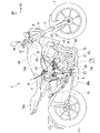
- FIG. 2 is a cross-sectional view of the transmission and change mechanism of the motorcycle; 2 is a block diagram of the transmission system of the motorcycle; FIG. FIG. 4 is an explanatory diagram showing transitions of clutch control modes of the motorcycle; FIG. 2 is a V arrow view of FIG. 1 and shows an axial view of the clutch actuator.
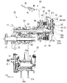
- FIG. 4 is a developed cross-sectional view along the axial direction of the clutch actuator;
- FIG. 4 is a perspective view of a release shaft that operates a clutch device;
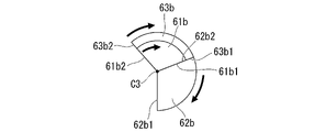
- FIG. 8 is a cross-sectional view taken along line VIII-VIII of FIG. 7;
- FIG. 9 is a cross-sectional view corresponding to FIG.
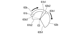
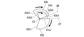
- FIG. 8 showing the action of the release shaft in the half-clutch region, and showing the drive by the clutch actuator
- FIG. 9 is a cross-sectional view corresponding to FIG. 8 showing the action of the release shaft in the half-clutch region, and showing manual intervention.
- FIG. 9 is a cross-sectional view corresponding to FIG. 8 showing the action of the release shaft at the standby position, and showing the time when the clutch actuator is driven;
- FIG. 9 is a cross-sectional view corresponding to FIG. 8 showing the action of the release shaft at the standby position, and showing manual intervention.
- FIG. 7 is a cross-sectional view corresponding to FIG.
- Fig. 13 is a graph corresponding to Fig. 12 and showing the first effect of the embodiment; Fig. 13 is a graph corresponding to Fig. 12 and showing the second effect of the embodiment; 4 is a graph showing changes in engine speed when a clutch device is engaged; 4 is a flowchart showing engine speed control processing using detection of operation torque.
- the present embodiment is applied to a motorcycle 1 as an example of a saddle type vehicle.
- a front wheel 2 of the motorcycle 1 is supported by lower ends of a pair of left and right front forks 3 .
- Upper portions of the left and right front forks 3 are supported by a head pipe 6 at the front end of the body frame 5 via a steering stem 4 .
- a bar-type steering handle 4a is attached to the top bridge of the steering stem 4. As shown in FIG.
- the vehicle body frame 5 includes a head pipe 6, a main frame 7 extending downward and rearward from the head pipe 6 at the center in the vehicle width direction (left-right direction), a pivot frame 8 provided below the rear end of the main frame 7, and a main frame.
- a seat frame 9 connected to the rear of the frame 7 and the pivot frame 8 is provided.
- a front end portion of a swing arm 11 is pivotally supported on the pivot frame 8 so as to be able to swing.
- a rear wheel 12 of the motorcycle 1 is supported at the rear end of the swing arm 11 .
- a power unit PU including the prime mover of the motorcycle 1 is suspended below the main frame 7 .
- the power unit PU integrally has an engine (internal combustion engine, prime mover) 13 located on the front side thereof and a transmission 21 located on the rear side thereof.
- the engine 13 is, for example, a multi-cylinder engine in which the rotation axis of the crankshaft 14 extends in the left-right direction (vehicle width direction).
- the transmission 21 is a stepped transmission.
- the transmission 21 has a main shaft 22 , a counter shaft 23 , and a transmission gear group 24 straddling both shafts 22 , 23 .
- Countershaft 23 constitutes an output shaft of transmission 21 and thus power unit PU.
- a left end portion of the countershaft 23 projects to the rear left side of the transmission case 17 and is connected to the rear wheel 12 via the chain type transmission mechanism.
- the main shaft 22 and countershaft 23 of the transmission 21 are arranged behind the crankshaft 14 .
- a clutch device 26 is coaxially arranged at the right end of the main shaft 22 .
- the clutch device 26 connects and disconnects power transmission between the crankshaft 14 of the engine 13 and the main shaft 22 of the transmission 21 .
- the clutch device 26 is engaged and disengaged by at least one of the operation of the clutch operator by the passenger and the operation of the clutch actuator 50, which will be described in detail later.
- the clutch operator is the clutch lever 4b.
- the clutch device 26 is, for example, a wet multi-plate clutch, a so-called normally closed clutch. Rotational power of the crankshaft 14 is transmitted to the main shaft 22 via the clutch device 26 and transmitted from the main shaft 22 to the countershaft 23 via an arbitrary gear pair of the transmission gear group 24 .
- a drive sprocket 27 of the chain transmission mechanism is attached to the left end portion of the countershaft 23 that protrudes to the rear left side of the crankcase 15 .
- a change mechanism 25 for switching the gear pair of the transmission gear group 24 is accommodated.
- the change mechanism 25 has a hollow cylindrical shift drum 32 parallel to the shafts 22 and 23 .
- the change mechanism 25 operates the plurality of shift forks 32a. This operation is performed according to the pattern of lead grooves formed on the outer circumference of the shift drum 32 .
- the change mechanism 25 switches the gear pair used for power transmission between the shafts 22 and 23 in the transmission gear group 24 .
- the motorcycle 1 only the shift operation of the transmission 21 (foot operation of a shift pedal (not shown)) is performed by the driver, and the connection/disengagement operation of the clutch device 26 is electrically controlled according to the operation of the shift pedal. automatically. That is, the motorcycle 1 employs a so-called semi-automatic transmission system (automatic clutch type transmission system).
- the transmission system 30 includes a clutch actuator 50, an ECU 40 (Electronic Control Unit), various sensors 41-46, and various devices 47, 48, 50.
- the ECU 40 controls the operation of the ignition device 47 and the fuel injection device 48 and also controls the operation of the clutch actuator 50 .
- This control is based on detection information from the acceleration sensor 41, the gear position sensor 42, and the shift load sensor 43 (for example, a torque sensor), as well as various vehicle data from the throttle opening sensor 44, the vehicle speed sensor 45, the engine speed sensor 46, and the like. This is done based on state detection information and the like.
- the acceleration sensor 41 detects the behavior of the vehicle body.
- a gear position sensor 42 detects a gear position from the rotational angle of the shift drum 32 .
- the shift load sensor 43 detects the operating torque input to the shift spindle 31 (see FIG. 2) of the change mechanism 25 .
- a throttle opening sensor 44 detects the throttle opening.
- a vehicle speed sensor 45 detects the vehicle speed.
- An engine speed sensor 46 detects the engine speed.
- the clutch actuator 50 controls the operating torque applied to the release shaft 53 in order to connect and disconnect the clutch device 26.
- the clutch actuator 50 includes an electric motor 52 (hereinafter simply referred to as the motor 52 ) as a drive source and a speed reduction mechanism 51 that transmits the drive force of the motor 52 to the release shaft 53 .
- the clutch device 26 of the embodiment is a multi-plate clutch in which a plurality of clutch plates 35 are laminated in the axial direction, and is a wet clutch arranged in an oil chamber inside the right cover 17a.
- the clutch device 26 includes a clutch outer 33 , a clutch center 34 and a plurality of clutch plates 35 .
- the clutch outer 33 is driven by constant transmission of rotational power from the crankshaft 14 .
- the clutch center 34 is arranged inside the clutch outer 33 and supported by the main shaft 22 so as to be integrally rotatable.
- a plurality of clutch plates 35 are laminated between the clutch outer 33 and the clutch center 34 to frictionally engage them.
- a pressure plate 36 having approximately the same diameter as the clutch plates 35 is arranged on the right side (outside in the vehicle width direction) of the laminated clutch plates 35 .
- the pressure plate 36 receives the elastic load of the clutch spring 37 and is urged leftward, and presses (frictionally engages) the stacked clutch plates 35 with each other.
- the clutch device 26 enters a connected state in which power can be transmitted.
- the clutch device 26 is a normally closed clutch that is normally connected when there is no external input.
- the pressure contact (frictional engagement) is released by operating the release mechanism 38 inside the right cover 17a.
- the release mechanism 38 is operated by at least one of the operation of the clutch lever 4 b by the passenger and the application of torque by the clutch actuator 50 .
- An eccentric cam portion 38a is provided on the lower portion of the release shaft 53 located inside the right cover 17a.
- the eccentric cam portion 38 a is engaged with the right end portion of the lifter shaft 39 .
- the release shaft 53 rotates about its axis, thereby moving the lifter shaft 39 rightward by the action of the eccentric cam portion 38a.
- the lifter shaft 39 is configured to reciprocate integrally with the pressure plate 36 of the clutch device 26 . Therefore, when the lifter shaft 39 moves rightward, the pressure plate 36 moves (lifts) rightward against the biasing force of the clutch spring 37 . As a result, the frictional engagement between the laminated clutch plates 35 is released. As a result, the normally closed clutch device 26 is brought into a disengaged state in which power cannot be transmitted.
- release mechanism 38 is not limited to an eccentric cam mechanism, and may be provided with a rack and pinion, a feed screw, or the like.
- the mechanism that connects the clutch lever 4b and the driven clutch lever 54 is not limited to the operation cable 54c, and may be provided with a rod, a link, or the like.
- the clutch control device 40A of this embodiment has three clutch control modes.
- the clutch control mode has an auto mode M1 for automatic control, a manual mode M2 for manual operation, and a manual intervention mode M3 for temporary manual operation.
- the clutch control mode appropriately transitions between the three modes according to the operation of the clutch control mode changeover switch 49 and the clutch lever 4b (see FIG. 3 for both).
- a target including the manual mode M2 and the manual intervention mode M3 is referred to as a manual system M2A.
- the auto mode M1 is a mode in which the clutch device 26 is controlled by calculating a clutch capacity suitable for the running state in accordance with automatic start/shift control.
- the manual mode M2 is a mode in which the clutch capacity is calculated and the clutch device 26 is controlled according to the clutch operation instruction from the passenger.
- the manual intervention mode M3 is a temporary manual operation mode in which a clutch operation instruction from the passenger is received during the automatic mode M1, the clutch capacity is calculated from the clutch operation instruction, and the clutch device 26 is controlled. For example, if the occupant stops operating the clutch lever 4b (completely released state) during the manual intervention mode M3, it may be set to return to the auto mode M1.
- the clutch control device 40A starts control from the clutch-on state (engagement state) in auto mode M1. Further, the clutch control device 40A is set to return to the clutch-on state in the auto mode M1 when the engine 13 is stopped (when the system is off). In the normally closed clutch device 26, there is no need to supply power to the motor 52 of the clutch actuator 50 when the clutch is on. On the other hand, power supply to the motor 52 is maintained in the clutch-off state (disconnected state) of the clutch device 26 .
- Auto mode M1 basically performs clutch control automatically.
- Auto mode M1 enables the motorcycle 1 to run without lever operation.
- the clutch capacity is controlled based on the throttle opening, engine speed, vehicle speed, shift sensor output, and the like.
- the motorcycle 1 can be started only by operating the throttle without engine stall (engine stop or engine stall).
- the motorcycle 1 can be shifted only by a shift operation.
- the automatic mode M1 when the passenger grips the clutch lever 4b, the mode is switched to the manual intervention mode M3. Thereby, it is possible to arbitrarily disengage the clutch device 26 .
- the clutch capacity can be controlled by the driver's lever operation (that is, the clutch device 26 can be connected and disconnected).
- the auto mode M1 and the manual mode M2 are mutually switchable. This switching is performed, for example, by operating the clutch control mode switching switch 49 (see FIG. 3) while the motorcycle 1 is stopped.
- the clutch control device 40A may include an indicator that indicates that the lever operation is effective when transitioning to the manual system M2A (manual mode M2 or manual intervention mode M3).
- clutch control is basically performed manually.
- the manual mode M2 can control the clutch capacity according to the operating angle of the clutch lever 4b (and thus the operating angle of the driven clutch lever 54). Thereby, it is possible to control the connection/disengagement of the clutch device 26 according to the passenger's intention. Even in manual mode M2, clutch control can automatically intervene when shift operation is performed without clutch operation.
- the operating angle of the driven clutch lever 54 will be referred to as the driven clutch lever operating angle.
- the clutch actuator 50 automatically connects and disconnects the clutch device 26 .
- manual clutch operation is performed on the clutch lever 4b, so that the manual operation can be temporarily intervened in the automatic control of the clutch device 26 (manual intervention mode M3).
- a clutch lever 4b as a manual clutch operator is attached to the base end side (inner side in the vehicle width direction) of the left grip of the steering handle 4a.
- the clutch lever 4b is attached via a lever holder 4c (see FIG. 2).
- the lever holder 4c is provided with a lever operation sensor 4d (see FIG. 3).
- the lever operation sensor 4d detects the amount of operation (rotational angle) of the clutch lever 4b, converts the amount of operation into an electric signal, and outputs the electric signal.
- the ECU 40 can control the operation of the clutch device 26 based on the output of the lever operation sensor 4d.
- the lever operation sensor 4d may be a switch that detects whether or not the clutch lever 4b is operated.
- the clutch lever 4b is connected to a driven clutch lever 54 attached to the release shaft 53 of the clutch device 26 via an operation cable 54c.
- the driven clutch lever 54 is attached to an upper end portion of the release shaft 53 that protrudes upward from the right cover 17a so as to rotate integrally therewith.
- the handle switch attached to the steering handle 4a is provided with the clutch control mode changeover switch 49 (see FIG. 3). This allows the occupant to easily switch the clutch control mode during normal driving.
- a clutch actuator 50 is attached to the rear upper portion of the right cover 17a on the right side of the crankcase 15.
- the clutch actuator 50 includes a motor 52 and a speed reduction mechanism 51.
- the motor 52 is, for example, a DC motor, and is arranged, for example, in parallel with the release shaft 53 in the axial direction.
- the motor 52 is arranged so that the drive shaft 55 protrudes upward.
- the reduction mechanism 51 transmits the driving force of the motor 52 to the release shaft 53 .
- multiple (two) motors 52 are provided for a single clutch actuator 50 .
- the motor 52 located on the vehicle front side of the clutch actuator 50 is referred to as a first motor 521
- the motor 52 located on the vehicle rear side and vehicle width direction inner side with respect to the first motor 521 is referred to as a second motor 522 .
- Lines C01 and C02 in the figure indicate central axes (drive axes) of the motors 521 and 522, respectively.
- both motors 521 and 522 may be collectively referred to as motor 52 .
- both axes C01 and C02 may be collectively referred to as axis C0.
- the deceleration mechanism 51 decelerates the rotational power output from the motor 52 and transmits it to the release shaft 53 .
- the reduction mechanism 51 includes, for example, a gear train axially parallel to the release shaft 53 .
- the reduction mechanism 51 includes a drive gear 55a, a first idle gear 57a, a first small diameter gear 57b, a second idle gear 58a, a second small diameter gear 58b, a driven gear 63a, and a gear case 59.
- the drive gear 55a is provided integrally with the drive shaft 55 of each motor 521,522.
- Each drive gear 55a meshes with the first idle gear 57a.
- the first small diameter gear 57b is provided coaxially with the first idle gear 57a.
- the second idle gear 58a meshes with the first small diameter gear 57b.
- the second small diameter gear 58b is provided coaxially with the second idle gear 58a.
- the driven gear 63a meshes with the second small diameter gear 58b.
- the gear case 59 accommodates each gear.
- the first idle gear 57a and the first small diameter gear 57b are rotatably supported by the first support shaft 57c.
- the first idle gear 57a, the first small diameter gear 57b and the first support shaft 57c constitute the first idle shaft 57.
- the second idle gear 58a and the second small-diameter gear 58b are rotatably supported by a second support shaft 58c.
- the second idle gear 58a, the second small diameter gear 58b and the second support shaft 58c constitute a second idle shaft 58.
- the first support shaft 57c and the second support shaft 58c are rotatably supported by the gear case 59, respectively.
- the second idle gear 58a is a sector gear centered on the second support shaft 58c.
- the second idle gear 58a is provided so as to extend forward and outward in the vehicle width direction of the second support shaft 58c.
- line C1 indicates the center axis of the first idle shaft 57
- line C2 indicates the center axis of the second idle shaft 58, respectively.
- the driven gear 63a is provided on the release shaft 53 so as to be integrally rotatable.
- the driven gear 63 a is a sector gear centered on the release shaft 53 .
- the driven gear 63 a is provided so as to extend forward of the release shaft 53 .
- a gear on the downstream side of the reduction mechanism 51 has a small rotation angle. Therefore, the second idle gear 58a and the driven gear 63a can be sector gears with a small rotation angle.
- a system is configured in which the clutch actuator 50 directly connects and disconnects the clutch device 26 .
- Each gear is a flat spur gear with reduced thickness in the axial direction
- the gear case 59 is also formed in a flat shape with reduced thickness in the axial direction. This makes the speed reduction mechanism 51 less noticeable when viewed from the side of the vehicle.
- a first rotation angle sensor 57d and a second rotation angle sensor 58d are provided on the upper surface side of the gear case 59 .
- a first rotation angle sensor 57d and a second rotation angle sensor 58d are connected to one end of each of the first idle shaft 57 and the second idle shaft 58 to detect their rotation angles.
- the motor 52 is arranged to protrude downward from the front of the gear case 59 .
- the right cover 17a has a bulging portion 17b that bulges outward in the vehicle width direction in the following range.
- the range is a circular range coaxial with the clutch device 26 when viewed from the side of the vehicle.
- a cover concave portion 17c is formed in a portion of the bulging portion 17b facing rearward and upward.
- the cover recessed portion 17c changes the outer surface inward in the vehicle width direction with respect to the remaining portion.
- a lower end portion of the cover concave portion 17c is a stepped portion 17d that changes the outer surface of the bulging portion 17b in a stepped manner.
- the upper portion of the release shaft 53 protrudes obliquely upward and rearward from the stepped portion 17d.
- the driving force of the motor 52 is decelerated as follows and transmitted to the release shaft 53. That is, the driving force of the motor 52 is reduced between the drive gear 55a and the first idle gear 57a, reduced between the first small diameter gear 57b and the second idle gear 58a, and further reduced between the second small diameter gear 58b. and the driven gear 63a.
- the release shaft 53 is divided into a plurality of elements so as to be rotatable by separately receiving the input from the clutch actuator 50 and the input by the operation of the passenger.
- the release shaft 53 includes an upper release shaft 61 forming an upper portion, a lower release shaft 62 forming a lower portion, and an intermediate release shaft 63 .
- the intermediate release shaft 63 is arranged across the lower end of the upper release shaft 61 and the upper end of the lower release shaft 62 .
- the upper release shaft 61 has a cylindrical shape.
- the upper release shaft 61 is rotatably supported by the upper boss portion 59b of the gear case 59. As shown in FIG. An upper end portion of the upper release shaft 61 protrudes outside the gear case 59 .
- a driven clutch lever 54 is supported by the upper end of the upper release shaft 61 so as to be integrally rotatable.
- a return spring 54 s is attached to the driven clutch lever 54 . The return spring 54s applies an urging force to the driven clutch lever 54 in a direction opposite to the rotation (rotation in the clutch disengaging direction) due to the operation of the clutch lever 4b.
- the lower release shaft 62 has a cylindrical shape. A lower portion of the lower release shaft 62 is rotatably supported inside the right cover 17a. A lower portion of the lower release shaft 62 faces the inside of the gear case 59 . An eccentric cam portion 38a of the release mechanism 38 is formed in the lower portion. A lower return spring 62 s is attached to the lower end of the lower release shaft 62 . The lower return spring 62s applies an urging force to the lower release shaft 62 in a direction opposite to the rotation in the clutch disengaging direction.
- the lower end of the upper release shaft 61 is provided with a manual operation side cam 61b extending in the axial direction and having a fan-shaped cross section.
- a clutch-side cam 62b extending in the axial direction and having a fan-shaped cross section is provided.
- the clutch side cam 62b is provided in a range avoiding the manual operation side cam 61b in the circumferential direction.
- the one circumferential side surface 61b1 of the manual operation side cam 61b presses the other circumferential side surface 62b2 of the clutch side cam 62b, and the lower release shaft 62 can be rotated (see FIGS. 9B and 10B). .
- the intermediate release shaft 63 has a cylindrical shape.
- the intermediate release shaft 63 can be inserted through an engaging portion (upper and lower shaft engaging portion) between the lower end portion of the upper release shaft 61 and the upper end portion of the lower release shaft 62 .
- a driven gear 63a is supported by the intermediate release shaft 63 so as to be rotatable therewith.
- the intermediate release shaft 63 is provided with a control operation side cam 63b extending in the axial direction and having a fan-shaped cross section.
- the control operation side cam 63b overlaps the clutch side cam 62b in the axial direction while avoiding the clutch side cam 62b of the lower release shaft 62 in the circumferential direction.
- the one circumferential side surface 63b1 of the control operation side cam 63b presses the other circumferential side surface 62b2 of the clutch side cam 62b, and the lower release shaft 62 can be rotated.
- control operation side cam 63b is arranged to avoid the manual operation side cam 61b of the upper release shaft 61 in the axial direction or radial direction. This allows the lower release shaft 62 to rotate independently of the upper release shaft 61 when transmitting the input from the clutch actuator 50 to the clutch-side cam 62b. Further, when there is a manual operation, the upper release shaft 61 can be rotated independently of the intermediate release shaft 63 on the control side.
- the other circumferential side surface 63b2 of the control operation side cam 63b and the one circumferential side surface 62b1 of the clutch side cam 62b are separated from each other in the circumferential direction.
- the lower release shaft 62 can rotate independently of the intermediate release shaft 63 when the clutch side cam 62b receives an input from the manual operation side cam 63b.
- clutch actuator 50 rotatably holds upper release shaft 61 and intermediate release shaft 63 with gear case 59 .
- Clutch actuator 50 includes an upper release shaft 61 and an intermediate release shaft 63 to form an integrated actuator unit 50A.
- the lower release shaft 62 is rotatably held by the right cover 17a.
- An opening 17e and a fastening portion 17f of the gear case 59 are provided in the stepped portion 17d of the cover recess 17c of the right cover 17a.
- the upper end of the lower release shaft 62 protrudes from the opening 17e.
- An opening 59c is provided in a portion of the gear case 59 facing the stepped portion 17d of the recessed cover 17c. The opening 59 c allows the upper end of the lower release shaft 62 to face the inside of the gear case 59 .
- a linear release shaft 53 is constructed.
- the release shaft 53 is configured by connecting an upper release shaft 61, an intermediate release shaft 63, and a lower release shaft 62 to each other.
- the power unit PU of the embodiment can be configured as follows for a manual clutch type power unit in which the connecting and disconnecting operation of the clutch device 26 is not performed by electric control but by the driver's operation. That is, the power unit PU can be configured by replacing the right cover 17a and the release shaft 53 and retrofitting the actuator unit 50A. Therefore, the actuator unit 50A can be attached to a power unit of a different model. Therefore, it is possible to easily configure a semi-automatic transmission system (automatic clutch type transmission system) by sharing the actuator unit 50A among many models.
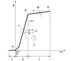
- the graph in FIG. 12 represents the clutch characteristics in the auto mode M1.
- the vertical axis indicates the torque (Nm) applied to the driven clutch lever 54 and the clutch capacity (%)
- the horizontal axis indicates the operating angle (deg) of the driven clutch lever 54 .
- the operating angle of the driven clutch lever 54 is the operating angle of the lower release shaft 62 .
- the torque of driven clutch lever 54 is the torque of lower release shaft 62 .
- This torque corresponds to a torque value calculated by multiplying the following primary torque value by the speed reduction ratio of the speed reduction mechanism 51 .
- the primary torque value is obtained based on the current value supplied to the motor 52 from the correlation between the current supplied to the motor 52 and the torque generated by the motor 52 .
- the torque of the driven clutch lever 54 will be referred to as driven clutch lever torque.
- a line L11 in the graph indicates the correlation between the driven clutch lever operating angle and the driven clutch lever torque.
- a line L12 in the graph indicates the correlation between the driven clutch lever operating angle and the clutch capacity.
- the line L11 is also a line indicating the output value (reference output value) of the clutch actuator 50 when the clutch device 26 is engaged and disengaged without intervention of manual operation.
- the one circumferential side surface 61b1 of the manual operation side cam 61b of the release shaft 53 does not press the other circumferential side surface 62b2 of the clutch side cam 62b.
- the manual operation side cam 61b is separated from the clutch side cam 62b by the biasing force of the return spring 54s (indicated by the dashed line in FIG. 8).
- the driven clutch lever 54 is in a play state in which the manual operation side cam 61b can move toward and away from the clutch side cam 62b by an angle A1 in the drawing.
- one circumferential side surface 63b1 of the control operation side cam 63b is in contact with the other circumferential side surface 62b2 of the clutch side cam 62b.
- the driven clutch lever operating angle increases and passes through the play area A
- the driven clutch lever operating angle shifts to the half-clutch area B.
- the driven clutch lever torque starts increasing due to the operation of the motor 52 .
- the control operation side cam 63b presses the clutch side cam 62b, causing the lower release shaft 62 to rotate.
- the release mechanism 38 lifts the clutch device 26 to reduce the clutch capacity. That is, the clutch device 26 is in a half-clutch state in which partial power transmission is possible.
- Symbol SP in FIG. 12 indicates the start position (operation start position) of the operation where the play area A is switched to the half-clutch area B.
- the manual operation side cam 61b contacts the clutch side cam 62b. At this time, the manual operation side cam 61b cooperates with the control operation side cam 63b to rotate the lower release shaft 62 (see FIG. 9B).
- the driven clutch lever torque sharply increases as the driven clutch lever operating angle increases, causing the clutch device 26 to operate to the disengagement side.
- a buffer region B1 is set in which the increase in the driven clutch lever torque with respect to the increase in the driven clutch lever operating angle is moderated.
- the clutch capacity sharply decreases as the driven clutch lever operating angle increases so as to be inversely proportional to the increase in driven clutch lever torque.
- the clutch capacity moderates its decrease as the driven clutch lever torque increases moderately.
- the increase in the driven clutch lever torque becomes slower than in the buffer region B1.
- the region after the touch point TP in the driven clutch lever actuation angle is, for example, a clutch disengagement region C where the clutch capacity remains equivalent to "0".
- the clutch disengagement region C is, for example, an operation margin region for the driven clutch lever 54 and the like to operate up to the mechanical operation limit position.
- the driven clutch lever torque slightly increases. This increment corresponds to the increment of the clutch spring load accompanying the movement of the lift component of the clutch device 26 .
- a standby position DP is set in the middle of the clutch disengagement region C.
- the following driven clutch lever torque is applied.
- the driven clutch lever torque at this time is slightly higher than the touch point TP at which the clutch device 26 starts connection.
- some torque transfer may occur due to operating errors.
- the driven clutch lever torque up to the torque of the standby position DP the torque transmission of the clutch device 26 is completely interrupted.
- a driven clutch lever torque slightly lower than that at the full lift position EP is applied, so that the clutch device 26 can be disabled. That is, at the standby position DP, it is possible to cancel the looseness of each part of the clutch device 26 and the reaction force of the action, and the like, and the action response when the clutch device 26 is engaged can be enhanced.
- the operation start position SP and the touch point TP are determined as follows. That is, the point at which the driven clutch lever torque rises (the starting point of the half-clutch region B) is the operation start position SP.
- a touch point TP is the point at which the clutch device 26 is completely disengaged (the end point of the half-clutch region B).
- the touch point TP and the operation start position SP are determined as follows. That is, the touch point TP is the point at which the clutch device 26 starts to engage. Further, the point at which the clutch device 26 is completely connected is the operation start position SP.
- the drive of motor 52 is controlled based on the lift load.
- the clutch spring load is set in advance.
- the lift load acting on the clutch device 26 (the operation load against the clutch spring load) is estimated according to the driven clutch lever torque.
- a load obtained by subtracting the lift load from the clutch spring load is used as the clutch pressing load that actually acts on the clutch device 26 .
- Clutch capacity is determined by "clutch pressing load/clutch spring load”.
- the electric power supplied to the motor 52 is controlled so that the clutch capacity becomes the target value, and the driven clutch lever torque and thus the lift load are controlled.
- a motor current value and a lever operation angle at each of the operation start position SP and the touch point TP are set to predetermined values in advance. Alternatively, the motor current value and the lever operating angle are set by learning control when the power of the motorcycle 1 is turned on or off, as will be described later.
- sensing configuration is the following configuration. That is, a current sensor 40b is provided in the motor control device (ECU 40), and the detected value is converted into motor torque and further converted into driven clutch lever torque (clutch operation torque).
- the following control is performed until the increment of the driven clutch lever operating angle reaches or exceeds a predetermined angle. That is, the motor 52 is feedback-controlled so that the torque d2 after the driven clutch lever torque is reduced by the threshold value d1 is maintained. As a result, it is possible to prevent discomfort caused by sudden loss of torque from the motor 52 after the clutch lever 4b is operated. After the increment of the driven clutch lever operating angle becomes equal to or greater than the specified angle, the driven clutch lever torque is gradually decreased (see G section in the figure). As a result, it is possible to suppress power consumption due to continuous driving of the motor 52 while suppressing the uncomfortable feeling.
- the drive of the motor 52 is controlled based on the lever position (angle).
- the increase in the driven clutch lever torque accompanying the lift of the clutch device 26 is small. Therefore, in the clutch disengagement region C, the electric power supplied to the motor 52 is controlled based on the driven clutch lever operating angle. As a result, it is possible to more finely control the disengagement amount of the clutch device 26 after the touch point TP at which the clutch device 26 starts to be connected.
- first idle shaft 57 and the second idle shaft 58 are provided with a first rotation angle sensor 57d and a second rotation angle sensor 58d, respectively. Then, the values detected by these sensors can be converted into driven clutch lever operating angles (clutch operating angles). A pair of the first rotation angle sensor 57d and the second rotation angle sensor 58d are provided for failure, but only one of them may be provided.
- the upper limit of the torque applied by the control operation side cam 63b to the clutch side cam 62b is the torque up to the standby position DP.
- the torque until the clutch-side cam 62b exceeds the standby position DP and reaches the full-lift position EP is applied when a manual operation of gripping the clutch lever 4b intervenes.
- a torque that exceeds the standby position DP is applied from the manual operation side cam 61b to the clutch side cam 62b (see FIG. 10B).
- the control operation side cam 63b is separated from the clutch side cam 62b, and the motor output becomes substantially zero.
- the following control is performed from when the manual operation intervention is detected until the increment of the driven clutch lever operating angle reaches or exceeds a predetermined angle. That is, the motor output is maintained so that the driven clutch lever operating angle maintains the touch point TP, which is the substantial clutch disengagement position. This prevents the engine from stalling even when the clutch lever 4b is suddenly released after the intervention of the manual operation.
- the driven clutch lever operating angle (the rotation angle of the gear shaft of the reduction mechanism 51) is detected and controlled as follows. In other words, in the region up to the preset (or learned) touch point TP (half-clutch region B), the control is performed by increasing the weighting of the current value. In the area after the touch point TP (clutch disengagement area C), control is performed in which the weighting of the operating angle is increased.
- changes in the current value (converted to torque value) of the motor 52 with respect to the driven clutch lever operating angle are learned (updated) at predetermined timings, and the target value is set according to the state of the clutch device 26. do. Based on this target value and the detection value of the current sensor 40b of the ECU 40, the driving of the motor 52 is feedback-controlled.
- FIG. 15 shows the following cases when the clutch control mode is the manual system M2A (manual mode M2 or manual intervention mode M3). That is, FIG. 15 shows a case where the driver gradually releases the clutch lever 4b (clutch connection operation) from a state in which the clutch lever 4b is gripped (clutch disengaged state), such as when starting the motorcycle 1 .
- the transition of the engine speed in this case is indicated by a solid line L13.
- the ECU 40 performs the following control in order to avoid the engine stalling during the connecting operation as described above. That is, when the engine speed becomes equal to or lower than the engine stall determination value d2, the clutch actuator 50 is driven to avoid engine stall, and clutch control is intervened by the driving force of the clutch actuator 50 (engine stall avoidance control). That is, if there is a possibility of engine stall while the driver is performing an operation to release the clutch lever 4b (clutch engagement operation), the following control is performed. That is, the clutch actuator 50 is driven to limit the operation of the clutch device 26 toward the connection side.
- the operating state of the clutch device 26 is maintained in a state in which the clutch capacity is reduced halfway (a half-clutch state before being fully engaged).
- the engine speed is maintained near the threshold value d2 (see chain line L13a in the figure). Therefore, it is possible to prevent the engine speed from exceeding the threshold value d2 and continuing to decrease (ie, the engine stalling).
- the clutch capacity may be lowered too much.
- the engine 13 may rev up unexpectedly (increase in engine speed) (see chain line L13b in the figure), which may give the driver a great sense of discomfort.
- the following controls are possible by enabling detection of the clutch operation torque by manual operation by the driver. That is, it is possible to drive the clutch actuator 50 as necessary to apply the clutch operation torque and control the clutch capacity to an appropriate value as indicated by the line L13a. As a result, compared with the engine stall avoidance control that simply reduces the clutch capacity, it is possible to prevent the driver from feeling uncomfortable.
- the clutch control device 40A includes an operating force transmission mechanism 65.
- the operating force transmission mechanism 65 can transmit the driver's operating force to the clutch lever 4 b to the clutch device 26 .
- the operating force transmission mechanism 65 includes a clutch lever 4b, a lever holder 4c, an operating cable 54c, a driven clutch lever 54, a release shaft 53 and a lifter shaft 39.
- the operating force transmission mechanism 65 is equipped with an operating force sensor 66 that detects the driver's operating force.
- the operating force sensor 66 is, for example, a non-contact magnetostrictive sensor 66 .
- the operating force sensor 66 is attached to the upper release shaft 61 of the release shaft 53 .
- the operating force sensor 66 magnetically measures the torsion of the drive shaft to detect torque.
- the driver's operation is not hindered by the friction and resistance of the sensor.
- the sensor is easier to install than when using an adhesive strain gauge or the like.
- Coordinated control of the clutch actuator 50 according to the detection value of the operating force sensor 66 is performed when the engine speed becomes equal to or less than the threshold value (engine stall determination value) d2. That is, the cooperative control is performed when it is determined that the clutch actuator 50 needs to be driven (when it is determined that there is a possibility of the engine stalling), and is in a standby state in other situations.
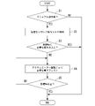
- step S1 it is determined whether or not the clutch lever 4b has been manually operated. This determination is made, for example, by turning ON/OFF a lever operation sensor 4d provided in the lever holder 4c according to the operation of the clutch lever 4b.
- step S1 If YES (manual operation is present) in step S1, the process proceeds to step S2. In step S2, manual operation torque is detected using the magnetostrictive sensor 66. FIG. If NO (no manual operation) in step S1, the process is once terminated. After the operation torque is detected in step S2, the process proceeds to step S3. In step S3, it is determined whether or not the manual operation torque detected in step S2 is greater than or equal to the operation force required to maintain the target engine speed.
- the final clutch operating torque in the release shaft 53 is the torque transmitted to the lower release shaft 62, which is the output shaft to the clutch device 26 side.
- This torque is the sum of the actuator torque and the manual operation torque.
- Actuator torque is the torque of intermediate release shaft 63 due to the drive of clutch actuator 50 .
- the manual operation torque is the torque of the upper release shaft 61 due to the operation of the clutch lever 4b.
- the actuator torque can be estimated (calculated) based on the drive current of the motor 52 and the reduction ratio of the speed reduction mechanism 51 .
- manual operation torque requires a dedicated operating force sensor 66 .
- a non-contact magnetostrictive sensor 66 is provided on the upper release shaft 61 as a sensor for detecting manual operation torque. As a result, friction and wear due to contact between the sensor and the shaft do not occur, and the driver's operation is not hindered. Also, the manual operation torque can be detected with high reliability.
- a torque sensor other than the magnetostrictive type may be, for example, a strain gauge or a combination of a torsion spring and an angle sensor.
- the operation force sensor 66 is not limited to the configuration provided on the release shaft 53 .
- the operating force sensor 66 may be, for example, a sensor provided on the clutch lever 4b and the lever holder 4c. Alternatively, a tension sensor provided on the operation cable 54c may be used.
- the "manipulation force required to maintain the target engine speed" in step S3 is the following manipulation force. That is, even if the engine speed decreases, it is an operating force capable of slipping the clutch device 26 (reducing the clutch capacity) so that the engine stall determination value d2 or more can be maintained. , clutch capacity, etc. are based on the specifications of the clutch device 26 or actual measurements. This relationship is approximated in tabular form or numerical formula and stored in the ECU 40 in advance.
- step S3 If YES in step S3 (more than the required operating force), the process is temporarily terminated. If NO (less than required operating force) in step S3, the process proceeds to step S4.
- step S4 the clutch actuator 50 is driven to start assisting to compensate for the insufficient operating force (clutch operating torque). After that, through step S5, the assist is continued until the engine speed becomes equal to or higher than the target value (engine stall determination value). Then, when the engine speed reaches or exceeds the target value (engine stall determination value d2), the process ends.
- the above steps S4 and S5 correspond to the cooperative control.
- the clutch control device 40A in the above embodiment includes the clutch device 26 for connecting and disconnecting power transmission between the engine 13 and the transmission 21, and the driving force for operating the clutch device 26. , an ECU 40 that drives and controls the clutch actuator 50 , and an operation force transmission mechanism 65 that can transmit the driver's operation force to the clutch lever 4 b to the clutch device 26 .
- the operating force transmission mechanism 65 is provided with an operating force sensor 66 that detects the operating force of the driver.
- the ECU 40 assist-drives the clutch actuator 50 according to the detection value of the operating force sensor 66 .
- the assist driving of the clutch actuator 50 can be performed in cooperation with the clutch operation (manual operation) by the driver.
- the driver's manual operation can be assisted by driving the clutch actuator 50 to avoid an engine stall, etc., while suppressing behavior that gives a sense of incongruity.
- the operating force transmission mechanism 65 receives the operating force of the driver and the driving force of the clutch actuator 50, and transmits the operating force and the driving force to the clutch device 26 side.
- a release shaft 53 is provided.
- the operating force sensor 66 is attached to the release shaft 53 . According to this configuration, by attaching the operation force sensor 66 to the release shaft 53 that receives both the operation force of the driver and the driving force of the clutch actuator 50, the following effects are obtained. That is, the driver's operation force can be detected at the release shaft 53 where the driver's operation force and the driving force of the clutch actuator 50 join. As a result, when cooperatively controlling the clutch actuator 50 according to the clutch operation by the driver, it is possible to appropriately detect the operation force of the driver.
- the operating force sensor 66 is a non-contact magnetostrictive sensor 66. As shown in FIG. According to this configuration, by detecting the driver's operating force using the non-contact magnetostrictive sensor 66, the following effects are obtained. That is, it is possible to detect the driver's operation force without hindering the driver's operation due to friction, resistance, or the like of the sensor. In addition, compared to the case of using an adhesive strain gauge or the like, the sensor can be easily installed, and mass productivity can be improved.
- the cooperative control according to the detection value of the operating force sensor 66 is performed when it is determined that the clutch actuator 50 needs to be driven according to the change in the control parameter (engine speed). done.
- the clutch actuator 50 it is possible to configure the clutch actuator 50 to operate only under the timing and under the conditions that require cooperative control. Therefore, power consumption and control load can be reduced compared to a configuration in which the clutch actuator 50 is always in operation.
- the clutch operating element is not limited to the clutch lever 4b, and may be a clutch pedal or other various operating elements.
- the clutch device is not limited to being arranged between the engine and the transmission, and may be arranged between the prime mover and any output object other than the transmission.
- the prime mover is not limited to an internal combustion engine, and may be an electric motor.
- the application is not limited to a saddle type vehicle in which the clutch operation is automated as in the above embodiment.
- a saddle-riding vehicle (a so-called saddle-riding vehicle equipped with a transmission that does not require a clutch operation) can shift gears by adjusting the driving force without manual clutch operation under predetermined conditions. type vehicle).
- the saddle type vehicle includes all types of vehicles in which the driver straddles the vehicle body, not only motorcycles (including motorized bicycles and scooter type vehicles), but also three-wheeled vehicles (one front wheel and two rear wheels). In addition, vehicles with two front wheels and one rear wheel are also included) or four-wheel vehicles, and vehicles including an electric motor as a prime mover are also included.
- the configuration in the above embodiment is an example of the present invention, and various modifications are possible without departing from the gist of the present invention.
Landscapes
- Engineering & Computer Science (AREA)
- General Engineering & Computer Science (AREA)
- Physics & Mathematics (AREA)
- Fluid Mechanics (AREA)
- Mechanical Engineering (AREA)
- Hydraulic Clutches, Magnetic Clutches, Fluid Clutches, And Fluid Joints (AREA)
- Mechanical Operated Clutches (AREA)
Abstract
Description
本願は、2021年3月31日に、日本に出願された特願2021-062322号に基づき優先権を主張し、その内容をここに援用する。
しかし、運転者によるクラッチ操作を考慮せず、単にクラッチを断接作動させると、運転者に違和感を与えるという課題がある。
この構成によれば、運転者によるクラッチ操作(マニュアル操作)と協調して、クラッチアクチュエータのアシスト駆動を行うことが可能となる。これにより、運転者によるマニュアル操作に対して、違和感のある挙動を抑えた上で、クラッチアクチュエータの駆動によるエンスト回避等のアシストを行うことができる。
この構成によれば、運転者の操作力およびクラッチアクチュエータの駆動力の両方を受けるレリーズシャフトに操作力センサを取り付けることで、以下の効果がある。すなわち、運転者の操作力とクラッチアクチュエータの駆動力とが合流するレリーズシャフトにおいて、運転者の操作力を検出することが可能となる。これにより、運転者によるクラッチ操作に応じてクラッチアクチュエータを協調制御する際に、運転者の操作力を適切に検知することができる。
この構成によれば、運転者の操作力を受ける上部レリーズシャフトに操作力センサを設けることで、運転者の操作力を適切に検知することができる。
この構成によれば、非接触の磁歪センサを用いて運転者の操作力を検出することで、以下の効果がある。すなわち、センサのフリクションおよび抵抗等で運転者の操作を阻害することなく、運転者の操作力を検知することができる。また、接着式のひずみゲージ等を用いる場合と比べて、センサの設置が容易であり、量産性を高めることができる。
この構成によれば、協調制御が必要となるタイミングや条件下でのみクラッチアクチュエータが稼働する構成とすることができる。このため、常にクラッチアクチュエータが稼働する構成に比べて、電力消費および制御負荷を抑えることができる。
図1に示すように、本実施形態は、鞍乗り型車両の一例としての自動二輪車1に適用されている。自動二輪車1の前輪2は、左右一対のフロントフォーク3の下端部に支持されている。左右フロントフォーク3の上部は、ステアリングステム4を介して、車体フレーム5の前端部のヘッドパイプ6に支持されている。ステアリングステム4のトップブリッジ上には、バータイプの操向ハンドル4aが取り付けられている。
図2を併せて参照し、変速機21は、有段式のトランスミッションである。変速機21は、メインシャフト22およびカウンタシャフト23ならびに両シャフト22,23に跨る変速ギヤ群24を有する。カウンタシャフト23は、変速機21ひいてはパワーユニットPUの出力軸を構成している。カウンタシャフト23の左端部は、変速機ケース17の後部左側に突出し、前記チェーン式伝動機構を介して後輪12に連結されている。
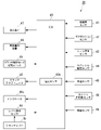
図3に示すように、上記変速システム30は、クラッチアクチュエータ50、ECU40(Electronic Control Unit、制御部)、各種センサ41~46、各種装置47,48,50を備えている。
ECU40は、点火装置47および燃料噴射装置48を作動制御するとともに、クラッチアクチュエータ50を作動制御する。この制御は、加速度センサ41、ギヤポジションセンサ42、およびシフト荷重センサ43(例えばトルクセンサ)からの検知情報、ならびにスロットル開度センサ44、車速センサ45およびエンジン回転数センサ46等からの各種の車両状態検知情報等に基づいてなされる。
加速度センサ41は、車体の挙動を検知する。ギヤポジションセンサ42は、シフトドラム32の回転角から変速段を検知する。シフト荷重センサ43は、チェンジ機構25のシフトスピンドル31(図2参照)に入力された操作トルクを検知する。スロットル開度センサ44は、スロットル開度を検知する。車速センサ45は、車速を検知する。エンジン回転数センサ46は、エンジン回転数を検知する。
図2、図11に示すように、実施形態のクラッチ装置26は、複数のクラッチ板35を軸方向で積層した多板クラッチであり、右カバー17a内の油室に配置された湿式クラッチである。クラッチ装置26は、クラッチアウタ33と、クラッチセンタ34と、複数のクラッチ板35と、を備えている。
クラッチアウタ33は、クランクシャフト14から回転動力が常時伝達されて駆動する。クラッチセンタ34は、クラッチアウタ33内に配置されてメインシャフト22に一体回転可能に支持される。複数のクラッチ板35は、クラッチアウタ33及びクラッチセンタ34の間に積層されてこれらを摩擦係合させる。
図2、図11に示すように、レリーズ機構38は、リフターシャフト39と、レリーズシャフト53と、を備えている。
リフターシャフト39は、メインシャフト22の右側部内に軸方向で往復動可能に保持される。レリーズシャフト53は、リフターシャフト39と軸方向を直交させて配置され、右カバー17aの外側部に軸心回りに回動可能に保持される。
図中線C3は、上下方向に延びるレリーズシャフト53の中心軸線を示す。レリーズシャフト53は、メインシャフト22の軸方向視(車両側面視)で、垂直方向に対して上側ほど後側に位置するように軸方向を後傾させている(図1参照)。レリーズシャフト53の上部は、右カバー17aの外側に突出し、このレリーズシャフト53の上部に、従動クラッチレバー54が一体回転可能に取り付けられている。従動クラッチレバー54は、クラッチレバー4bと操作ケーブル54cを介して連結されている。
図4に示すように、本実施形態のクラッチ制御装置40Aは、三種のクラッチ制御モードを有している。クラッチ制御モードは、自動制御を行うオートモードM1、手動操作を行うマニュアルモードM2、および一時的な手動操作を行うマニュアル介入モードM3、を有している。クラッチ制御モードは、前記三種のモード間で、クラッチ制御モード切替スイッチ49およびクラッチレバー4b(何れも図3参照)の操作に応じて適宜遷移する。なお、マニュアルモードM2およびマニュアル介入モードM3を含む対象をマニュアル系M2Aという。
この切り替えは、例えば、自動二輪車1の停車中に、クラッチ制御モード切替スイッチ49(図3参照)を操作することでなされる。なお、クラッチ制御装置40Aは、マニュアル系M2A(マニュアルモードM2又はマニュアル介入モードM3)への遷移時に、レバー操作が有効であることを示すインジケータを備えてもよい。
図1に示す自動二輪車1において、操向ハンドル4aの左グリップの基端側(車幅方向内側)には、クラッチ手動操作子としてのクラッチレバー4bが取り付けられている。クラッチレバー4bは、レバーホルダ4cを介して取り付けられている(図2参照)。
例えば、レバーホルダ4cには、レバー操作センサ4d(図3参照)が設けられている。例えば、レバー操作センサ4dは、クラッチレバー4bの操作量(回動角度)を検出し、この操作量を電気信号に変換して出力する。クラッチレバー4bの操作が有効な状態(マニュアル系M2A)において、ECU40は、レバー操作センサ4dの出力に基づき、クラッチ装置26の作動を制御可能である。例えば、レバー操作センサ4dは、クラッチレバー4bの操作の有無を検出するスイッチでもよい。
図1に示すように、クランクケース15右側の右カバー17aの後上部には、クラッチアクチュエータ50が取り付けられている。
図5、図6を併せて参照し、クラッチアクチュエータ50は、モータ52と、減速機構51と、を備えている。
モータ52は、例えばDCモータであり、例えばレリーズシャフト53と軸方向を平行にして配置されている。モータ52は、駆動軸55を上方に突出させるように配置されている。減速機構51は、モータ52の駆動力をレリーズシャフト53に伝達する。
駆動ギヤ55aは、各モータ521,522の駆動軸55に一体に設けられる。第一アイドルギヤ57aは、各駆動ギヤ55aが噛み合う。第一小径ギヤ57bは、第一アイドルギヤ57aと同軸に設けられる。第二アイドルギヤ58aは、第一小径ギヤ57bが噛み合う。第二小径ギヤ58bは、第二アイドルギヤ58aと同軸に設けられる。被動ギヤ63aは、第二小径ギヤ58bが噛み合う。ギヤケース59は、各ギヤを収容する。
図6~図8に示すように、レリーズシャフト53は、クラッチアクチュエータ50からの入力と、乗員の操作による入力と、を個別に受けて回動可能とするために、複数の要素に分割されている。
レリーズシャフト53は、上部を構成する上部レリーズシャフト61と、下部を構成する下部レリーズシャフト62と、中間レリーズシャフト63と、を備えている。中間レリーズシャフト63は、上部レリーズシャフト61の下端部と下部レリーズシャフト62の上端部とに跨って配置される。
下部レリーズシャフト62の上端部には、断面扇形をなして軸方向に延びるクラッチ側カム62bが設けられている。クラッチ側カム62bは、周方向で手動操作側カム61bを避けた範囲に設けられている。
中間レリーズシャフト63には、断面扇形をなして軸方向に延びる制御操作側カム63bが設けられている。
次に、実施形態のクラッチ制御について、図12のグラフを参照して説明する。図12のグラフは、前記オートモードM1におけるクラッチ特性をイメージしている。図12のグラフにおいて、縦軸は従動クラッチレバー54に付与されるトルク(Nm)およびクラッチ容量(%)、横軸は従動クラッチレバー54の作動角(deg)をそれぞれ示している。従動クラッチレバー54の作動角は、下部レリーズシャフト62の作動角である。
以下、従動クラッチレバー54のトルクを従動クラッチレバートルクという。従動クラッチレバー作動角と従動クラッチレバートルクとの相関をグラフ中線L11で示す。従動クラッチレバー作動角とクラッチ容量との相関をグラフ中線L12で示す。線L11は、マニュアル操作が介入しない状態でクラッチ装置26を断接する際の、クラッチアクチュエータ50の出力値(基準出力値)を示す線でもある。
半クラッチ領域Bにおいて、クラッチ容量は、従動クラッチレバートルクの増加に反比例するように、従動クラッチレバー作動角の増加に伴い急峻に減少する。半クラッチ領域Bの初期の緩衝領域B1において、クラッチ容量は、従動クラッチレバートルクの増加が緩やかなることに伴い、減少を緩やかにする。
逆に、クラッチ装置26が切断状態から接続側へ作動する際、タッチポイントTPおよび作動開始位置SPは以下のように定まる。すなわち、クラッチ装置26が接続し始めるポイントがタッチポイントTPである。また、クラッチ装置26が完全に接続するポイントが作動開始位置SPである。
係る制御では、まず、クラッチスプリング37の弾発力に基づき、予めクラッチスプリング荷重を設定する。次に、従動クラッチレバートルクに応じて、クラッチ装置26に作用するリフト荷重(クラッチスプリング荷重に抗する操作荷重)を推定する。そして、クラッチスプリング荷重からリフト荷重を減じた荷重を、実際にクラッチ装置26に作用させるクラッチ押付荷重とする。
前述のように、クラッチ切断領域Cでは、クラッチ装置26のリフトに伴う従動クラッチレバートルクの増加が少ない。このため、クラッチ切断領域Cでは、従動クラッチレバー作動角に基づき、モータ52への供給電力を制御する。これにより、クラッチ装置26が接続を開始するタッチポイントTP以降において、クラッチ装置26の切れ量をより細かく制御することが可能となる。
実施形態では、従動クラッチレバー作動角(減速機構51のギヤ軸の回転角)を検出し、以下のように制御する。すなわち、予め設定した(又は学習した)タッチポイントTPまでの領域(半クラッチ領域B)では、電流値の重み付けを増した制御とした。タッチポイントTP以降の領域(クラッチ切断領域C)では、作動角の重み付けを増した制御とした。
また、実施形態では、従動クラッチレバー作動角に対するモータ52の電流値(トルク値に換算)の変化を、予め定めたタイミングで学習(更新)し、クラッチ装置26の状況に応じた目標値を設定する。この目標値とECU40の電流センサ40bの検出値とに基づき、モータ52の駆動がフィードバック制御される。
以下、図15を参照し、実施形態の作用について説明する。図15の縦軸はエンジン回転数Ne(rpm)、横軸は時間t(sec)をそれぞれ示す。
図15は、クラッチ制御モードがマニュアル系M2A(マニュアルモードM2又はマニュアル介入モードM3)にある状態において、以下の場合を示す。すなわち、図15は、自動二輪車1の発進時等、運転者がクラッチレバー4bを握った状態(クラッチ切断状態)から徐々にクラッチレバー4bを解放する操作(クラッチ接続操作)を行う場合を示す。この場合のエンジン回転数の遷移を実線L13で示している。
まず、ステップS1で、クラッチレバー4bに対するマニュアル操作があったか否かを判定する。この判定は、例えば、レバーホルダ4cに設けたレバー操作センサ4dが、クラッチレバー4bの操作に応じてON/OFFすることでなされる。
ステップS2で操作トルクの検知を行った後、ステップS3に移行する。ステップS3では、ステップS2で検知したマニュアル操作トルクが、目標エンジン回転数の維持に必要な操作力以上か否かを判定する。
この構成によれば、運転者によるクラッチ操作(マニュアル操作)と協調して、クラッチアクチュエータ50のアシスト駆動を行うことが可能となる。これにより、運転者によるマニュアル操作に対して、違和感のある挙動を抑えた上で、クラッチアクチュエータ50の駆動によるエンスト回避等のアシストを行うことができる。
この構成によれば、運転者の操作力およびクラッチアクチュエータ50の駆動力の両方を受けるレリーズシャフト53に操作力センサ66を取り付けることで、以下の効果がある。すなわち、運転者の操作力とクラッチアクチュエータ50の駆動力とが合流するレリーズシャフト53において、運転者の操作力を検出することが可能となる。これにより、運転者によるクラッチ操作に応じてクラッチアクチュエータ50を協調制御する際に、運転者の操作力を適切に検知することができる。
この構成によれば、非接触の磁歪センサ66を用いて運転者の操作力を検出することで、以下の効果がある。すなわち、センサのフリクションおよび抵抗等で運転者の操作を阻害することなく、運転者の操作力を検知することができる。また、接着式のひずみゲージ等を用いる場合と比べて、センサの設置が容易であり、量産性を高めることができる。
この構成によれば、協調制御が必要となるタイミングや条件下でのみクラッチアクチュエータ50が稼働する構成とすることができる。このため、常にクラッチアクチュエータ50が稼働する構成に比べて、電力消費および制御負荷を抑えることができる。
上記実施形態のようにクラッチ操作を自動化した鞍乗り型車両への適用に限らない。例えば、マニュアルクラッチ操作を基本としながら、所定の条件下でマニュアルクラッチ操作を行わずに、駆動力を調整して変速を可能とする鞍乗り型車両(いわゆるクラッチ操作レスの変速装置を備える鞍乗り型車両)にも適用可能である。
また、前記鞍乗り型車両には、運転者が車体を跨いで乗車する車両全般が含まれ、自動二輪車(原動機付自転車及びスクータ型車両を含む)のみならず、三輪(前一輪かつ後二輪の他に、前二輪かつ後一輪の車両も含む)又は四輪の車両も含まれ、かつ電気モータを原動機に含む車両も含まれる。
そして、上記実施形態における構成は本発明の一例であり、当該発明の要旨を逸脱しない範囲で種々の変更が可能である。
13 エンジン(原動機)
21 変速機(出力対象)
26 クラッチ装置
40 ECU(制御部)
40A クラッチ制御装置
50 クラッチアクチュエータ
50A アクチュエータユニット
51 減速機構(伝動機構)
52 モータ(駆動源)
53 レリーズシャフト
65 操作力伝達機構
66 操作力センサ
66 磁歪センサ
Claims (5)
- 原動機(13)と出力対象(21)との間との間の動力伝達を断接するクラッチ装置(26)と、
前記クラッチ装置(26)を作動させるための駆動力を出力するクラッチアクチュエータ(50)と、
前記クラッチアクチュエータ(50)を駆動制御する制御部(40)と、
クラッチ操作子(4b)に対する運転者の操作力を前記クラッチ装置(26)に伝達可能とする操作力伝達機構(65)と、を備え、
前記操作力伝達機構(65)には、運転者の操作力を検出する操作力センサ(66)が備えられ、
前記制御部(40)は、前記操作力センサ(66)の検出値に応じて、前記クラッチアクチュエータ(50)を駆動させるクラッチ制御装置。 - 前記操作力伝達機構(65)は、前記運転者の操作力および前記クラッチアクチュエータ(50)の駆動力を受けるとともに、前記操作力および駆動力を前記クラッチ装置(26)側に伝達するレリーズシャフト(53)を備え、
前記操作力センサ(66)は、前記レリーズシャフト(53)に取り付けられている請求項1に記載のクラッチ制御装置。 - 前記レリーズシャフト(53)は、運転者の操作力を受ける上部レリーズシャフト(61)と、下部を構成する下部レリーズシャフト(62)と、前記上部レリーズシャフト(61)の下端部と前記下部レリーズシャフト(62)の上端部とに跨って配置される中間レリーズシャフト(63)と、を備え、
前記操作力センサ(66)は、前記上部レリーズシャフト(61)に取り付けられている請求項2に記載のクラッチ制御装置。 - 前記操作力センサ(66)は、非接触の磁歪センサ(66)である請求項1から3の何れか一項に記載のクラッチ制御装置。
- 前記操作力センサ(66)の検出値に応じた協調制御は、予め定めた制御パラメータの変化に応じて、前記クラッチアクチュエータ(50)の駆動が必要と判断したときに行われる請求項1から4の何れか一項に記載のクラッチ制御装置。
Priority Applications (3)
| Application Number | Priority Date | Filing Date | Title |
|---|---|---|---|
| DE112022001000.2T DE112022001000T5 (de) | 2021-03-31 | 2022-03-15 | Kupplungssteuereinrichtung |
| JP2023510896A JP7432061B2 (ja) | 2021-03-31 | 2022-03-15 | クラッチ制御装置 |
| US18/284,083 US11994180B1 (en) | 2021-03-31 | 2022-03-15 | Clutch control device |
Applications Claiming Priority (2)
| Application Number | Priority Date | Filing Date | Title |
|---|---|---|---|
| JP2021-062322 | 2021-03-31 | ||
| JP2021062322 | 2021-03-31 |
Publications (1)
| Publication Number | Publication Date |
|---|---|
| WO2022209869A1 true WO2022209869A1 (ja) | 2022-10-06 |
Family
ID=83459035
Family Applications (1)
| Application Number | Title | Priority Date | Filing Date |
|---|---|---|---|
| PCT/JP2022/011703 Ceased WO2022209869A1 (ja) | 2021-03-31 | 2022-03-15 | クラッチ制御装置 |
Country Status (4)
| Country | Link |
|---|---|
| US (1) | US11994180B1 (ja) |
| JP (1) | JP7432061B2 (ja) |
| DE (1) | DE112022001000T5 (ja) |
| WO (1) | WO2022209869A1 (ja) |
Cited By (2)
| Publication number | Priority date | Publication date | Assignee | Title |
|---|---|---|---|---|
| WO2024143335A1 (ja) * | 2022-12-26 | 2024-07-04 | 本田技研工業株式会社 | クラッチ制御装置 |
| WO2024201798A1 (ja) * | 2023-03-29 | 2024-10-03 | 本田技研工業株式会社 | クラッチ制御装置 |
Families Citing this family (1)
| Publication number | Priority date | Publication date | Assignee | Title |
|---|---|---|---|---|
| JP2026062329A (ja) * | 2024-09-30 | 2026-04-09 | 本田技研工業株式会社 | クラッチ制御装置および鞍乗り型車両 |
Citations (3)
| Publication number | Priority date | Publication date | Assignee | Title |
|---|---|---|---|---|
| JPS60129522U (ja) * | 1984-02-08 | 1985-08-30 | 川崎重工業株式会社 | 遊び自動調整装置付クラツチリリ−ス機構 |
| JP2010167798A (ja) * | 2009-01-20 | 2010-08-05 | Nissan Motor Co Ltd | ハイブリッド車両の制御装置 |
| WO2020213333A1 (ja) * | 2019-04-19 | 2020-10-22 | 本田技研工業株式会社 | クラッチ制御装置 |
Family Cites Families (3)
| Publication number | Priority date | Publication date | Assignee | Title |
|---|---|---|---|---|
| JPS60129522A (ja) | 1983-12-15 | 1985-07-10 | Shimizu Constr Co Ltd | スタツクレイン防止装置 |
| JP2005106246A (ja) | 2003-10-01 | 2005-04-21 | Suzuki Motor Corp | クラッチ操作装置 |
| JP7336089B2 (ja) | 2019-10-11 | 2023-08-31 | 大原パラヂウム化学株式会社 | 多孔性金属錯体造粒物の製造方法 |
-
2022
- 2022-03-15 US US18/284,083 patent/US11994180B1/en active Active
- 2022-03-15 WO PCT/JP2022/011703 patent/WO2022209869A1/ja not_active Ceased
- 2022-03-15 JP JP2023510896A patent/JP7432061B2/ja active Active
- 2022-03-15 DE DE112022001000.2T patent/DE112022001000T5/de active Pending
Patent Citations (3)
| Publication number | Priority date | Publication date | Assignee | Title |
|---|---|---|---|---|
| JPS60129522U (ja) * | 1984-02-08 | 1985-08-30 | 川崎重工業株式会社 | 遊び自動調整装置付クラツチリリ−ス機構 |
| JP2010167798A (ja) * | 2009-01-20 | 2010-08-05 | Nissan Motor Co Ltd | ハイブリッド車両の制御装置 |
| WO2020213333A1 (ja) * | 2019-04-19 | 2020-10-22 | 本田技研工業株式会社 | クラッチ制御装置 |
Cited By (3)
| Publication number | Priority date | Publication date | Assignee | Title |
|---|---|---|---|---|
| WO2024143335A1 (ja) * | 2022-12-26 | 2024-07-04 | 本田技研工業株式会社 | クラッチ制御装置 |
| JP7536073B2 (ja) | 2022-12-26 | 2024-08-19 | 本田技研工業株式会社 | クラッチ制御装置 |
| WO2024201798A1 (ja) * | 2023-03-29 | 2024-10-03 | 本田技研工業株式会社 | クラッチ制御装置 |
Also Published As
| Publication number | Publication date |
|---|---|
| US20240151278A1 (en) | 2024-05-09 |
| JP7432061B2 (ja) | 2024-02-15 |
| DE112022001000T5 (de) | 2023-12-07 |
| US11994180B1 (en) | 2024-05-28 |
| JPWO2022209869A1 (ja) | 2022-10-06 |
Similar Documents
| Publication | Publication Date | Title |
|---|---|---|
| JP7432061B2 (ja) | クラッチ制御装置 | |
| JP7462108B2 (ja) | クラッチ制御装置 | |
| US20260034984A1 (en) | Vehicle | |
| WO2022209634A1 (ja) | クラッチ制御装置 | |
| JP7474906B2 (ja) | クラッチ制御装置 | |
| JP2025096457A (ja) | 変速システム | |
| US20230095322A1 (en) | Clutch control device | |
| WO2024201798A1 (ja) | クラッチ制御装置 | |
| JP7457874B2 (ja) | クラッチ制御装置 | |
| WO2022209632A1 (ja) | クラッチ制御装置 | |
| JP7798518B2 (ja) | クラッチ制御装置 | |
| JP2023050298A (ja) | クラッチ制御装置 | |
| JP7566205B2 (ja) | クラッチ制御装置 |
Legal Events
| Date | Code | Title | Description |
|---|---|---|---|
| 121 | Ep: the epo has been informed by wipo that ep was designated in this application |
Ref document number: 22780089 Country of ref document: EP Kind code of ref document: A1 |
|
| DPE1 | Request for preliminary examination filed after expiration of 19th month from priority date (pct application filed from 20040101) | ||
| WWE | Wipo information: entry into national phase |
Ref document number: 2023510896 Country of ref document: JP |
|
| WWE | Wipo information: entry into national phase |
Ref document number: 18284083 Country of ref document: US Ref document number: 112023000148968 Country of ref document: IT |
|
| WWE | Wipo information: entry into national phase |
Ref document number: 112022001000 Country of ref document: DE |
|
| WWE | Wipo information: entry into national phase |
Ref document number: 202347068589 Country of ref document: IN |
|
| 122 | Ep: pct application non-entry in european phase |
Ref document number: 22780089 Country of ref document: EP Kind code of ref document: A1 |