WO2022209406A1 - 匂い成分保持部材、匂い提供装置、および匂い提供ユニット - Google Patents
匂い成分保持部材、匂い提供装置、および匂い提供ユニット Download PDFInfo
- Publication number
- WO2022209406A1 WO2022209406A1 PCT/JP2022/006607 JP2022006607W WO2022209406A1 WO 2022209406 A1 WO2022209406 A1 WO 2022209406A1 JP 2022006607 W JP2022006607 W JP 2022006607W WO 2022209406 A1 WO2022209406 A1 WO 2022209406A1
- Authority
- WO
- WIPO (PCT)
- Prior art keywords
- opening
- odor
- odor component
- internal space
- member according
- Prior art date
- Legal status (The legal status is an assumption and is not a legal conclusion. Google has not performed a legal analysis and makes no representation as to the accuracy of the status listed.)
- Ceased
Links
Images



Classifications
-
- A—HUMAN NECESSITIES
- A45—HAND OR TRAVELLING ARTICLES
- A45D—HAIRDRESSING OR SHAVING EQUIPMENT; EQUIPMENT FOR COSMETICS OR COSMETIC TREATMENTS, e.g. FOR MANICURING OR PEDICURING
- A45D34/00—Containers or accessories specially adapted for handling liquid toiletry or cosmetic substances, e.g. perfumes
- A45D34/02—Scent flasks, e.g. with evaporator
-
- A—HUMAN NECESSITIES
- A61—MEDICAL OR VETERINARY SCIENCE; HYGIENE
- A61L—METHODS OR APPARATUS FOR STERILISING MATERIALS OR OBJECTS IN GENERAL; DISINFECTION, STERILISATION OR DEODORISATION OF AIR; CHEMICAL ASPECTS OF BANDAGES, DRESSINGS, ABSORBENT PADS OR SURGICAL ARTICLES; MATERIALS FOR BANDAGES, DRESSINGS, ABSORBENT PADS OR SURGICAL ARTICLES
- A61L9/00—Disinfection, sterilisation or deodorisation of air
- A61L9/015—Disinfection, sterilisation or deodorisation of air using gaseous or vaporous substances, e.g. ozone
- A61L9/04—Disinfection, sterilisation or deodorisation of air using gaseous or vaporous substances, e.g. ozone using substances evaporated in the air without heating
- A61L9/12—Apparatus, e.g. holders, therefor
-
- B—PERFORMING OPERATIONS; TRANSPORTING
- B65—CONVEYING; PACKING; STORING; HANDLING THIN OR FILAMENTARY MATERIAL
- B65D—CONTAINERS FOR STORAGE OR TRANSPORT OF ARTICLES OR MATERIALS, e.g. BAGS, BARRELS, BOTTLES, BOXES, CANS, CARTONS, CRATES, DRUMS, JARS, TANKS, HOPPERS, FORWARDING CONTAINERS; ACCESSORIES, CLOSURES, OR FITTINGS THEREFOR; PACKAGING ELEMENTS; PACKAGES
- B65D83/00—Containers or packages with special means for dispensing contents
Definitions
- the present technology relates to an odor component holding member, an odor providing device, and an odor providing unit, and more specifically, to an odor component holding member and an odor providing device that open and close an air supply channel and an odor release channel to provide an odor.
- Patent Literature 1 discloses a shielding cylinder having a cylindrical shape, an inner cavity serving as an airway for transporting odorants, and having an opening on a part of the side surface, and a shielding cylinder containing odorants inside and provided on the outer surface of the shielding cylinder.
- an odor component container having an opening on the side surface of the shielding cylinder; and an air blower capable of blowing air at one end of the odor component transporting airway, wherein the shield cylinder and the odor component container rotate while being in close contact with each other.
- the odor component leaks from the fitting portion between the container holding the odor component and the case, or from an opening such as an odor entrance that communicates with the outside. This may cause problems such as deterioration (weakening due to volatilization and deterioration due to oxidation) of odor components, mixing, and melting of labels attached to cases or the like.
- the main purpose of the present technology is to provide an odor component holding member, an odor providing device, and an odor providing unit that can prevent the odor component from leaking through gaps such as fitting portions and openings.
- an internal space a first opening and a second opening that open the internal space to the outside, and a movable part that can open and close at least one of the first opening and the second opening.
- a plurality of housings arranged in a stack structure; and an odor component holder arranged in an internal space of one of the plurality of housings and holding an odor component;
- the portion, the second opening, the movable portion, and the odorant component retainer are arranged substantially parallel to the direction in which the plurality of housings are stacked, and the movable portion normally operates in the first opening and the odor component retainer.
- An odor component holding member is provided which seals the second opening and opens the first opening and/or the second opening when the internal space is opened.
- the internal space of any one of the plurality of housings may further include a deodorant for deodorizing residual odor components.
- the deodorant may be arranged at a position away from a ventilation channel of air passing through the internal space.
- the movable part has an operating shaft, a closing valve connected to an end of the operating shaft, and an elastic body biased in a closing direction of the first opening and/or the second opening. You may have
- the movable portion may have a tolerance absorbing portion that absorbs a tolerance between a first open/close position of the first opening and a second open/close position of the second opening.
- the movable portion may be a linear motion mechanism that linearly moves in the opening/closing direction of the first opening and the second opening.
- the movable part may have a detachable part that can be detached by a drive source and/or magnetic means.
- the odor component retainer may be disposed around the movable portion, may have a through-hole for allowing air to pass through, or may be porous.
- a locking mechanism may be further provided which seals the internal space in a steady state and opens the internal space when attached to an external device.
- a sealing structure may be formed in the fitting portion between the housings.
- the sealing structure may be threads and/or O-rings.
- the fitting portion may have an oil seal material and/or an elastic material.
- the surface may be made of a material selected from any one of low gas permeable resin, organic polymer, organic small molecule, organic metal, metal, metal film, or a combination of these. .
- the inner wall surface may be made of metal.
- the odor component holding member may be a cartridge attached to the odor providing device.
- an internal space a first opening and a second opening that open the internal space to the outside, and a movable opening that can open and close at least one of the first opening and the second opening.
- a plurality of housings arranged in a stack structure, and an odorant component holder arranged in an internal space of one of the plurality of housings and holding an odorant component.
- the present technology provides an odor providing unit in which a plurality of the above odor providing devices are arranged.
- the above effects are not necessarily limited, and together with the above effects or instead of the above effects, any of the effects shown in this specification or other effects that can be grasped from this specification may be played.
- FIG. 1 is a perspective view showing a configuration example of an odor providing device according to a first embodiment of the present technology
- FIG. It is a side sectional view showing an example of composition of an odor component retention member concerning a 1st embodiment of this art. It is a side sectional view showing an example of composition of an odor providing device concerning a 1st embodiment of this art. It is a side cross-sectional view showing an operation example of the odor providing device according to the first embodiment of the present technology. It is a side sectional view showing a modification of an odor component retention member concerning a 1st embodiment of this art.
- FIG. 3 is a partially enlarged view showing a modification of the odor component retainer according to the first embodiment of the present technology; It is a side sectional view showing a modification of sealing structure concerning a 1st embodiment of this art. It is a side sectional view showing a modification of sealing structure concerning a 1st embodiment of this art. It is a side sectional view showing an example of composition of an odor providing device concerning a 2nd embodiment of this art.
- FIG. 11 is a side cross-sectional view showing an operation example of the odor providing device according to the second embodiment of the present technology; FIG.
- FIG. 11 is a side cross-sectional view showing an operation example of the odor providing device according to the second embodiment of the present technology; It is a perspective view showing a configuration example of an odor providing unit according to a third embodiment of the present technology.
- FIG. 11 is a partial cross-sectional view showing a configuration example of an odor providing unit according to a third embodiment of the present technology;
- FIG. 14 is a side cross-sectional view showing a configuration example of an odor providing device according to a fourth embodiment of the present technology; 4 is a flow chart explaining an application example of the odor providing device.
- First embodiment (1) Configuration example of odor providing device (1-1) Overall configuration (1-2) Cartridge (smell component holding member) (1-3) Driving mechanism (2) Operation example of odor providing device (3) Modification of cartridge (4) Modification of odor component holder (5) Modification of sealing structure 2.
- Second embodiment (1) Configuration example of odor providing device (2) Operation example of odor providing device 3.
- Fourth embodiment (1) Configuration example of odor providing device (2) Operation example of odor providing device 5.
- FIG. 1 is a perspective view showing a configuration example of an odor providing device 100 according to this embodiment.
- FIG. 2 is a side cross-sectional view showing a configuration example of a cartridge (smell component holding member) 101 included in the smell providing device 100.
- FIG. 3 is a side cross-sectional view showing a configuration example of the odor providing device 100.
- FIG. 1 is a perspective view showing a configuration example of an odor providing device 100 according to this embodiment.
- FIG. 2 is a side cross-sectional view showing a configuration example of a cartridge (smell component holding member) 101 included in the smell providing device 100.
- FIG. 3 is a side cross-sectional view showing a configuration example of the odor providing device 100.
- FIG. 1 is a perspective view showing a configuration example of an odor providing device 100 according to this embodiment.
- FIG. 2 is a side cross-sectional view showing a configuration example of a cartridge (smell component holding member) 101 included in the smell providing device 100.
- an odor providing device 100 includes a cylindrical cartridge 101 as an odor component holding member, a cylindrical driving mechanism 102, and a tip of the cartridge 101 which is formed at the tip of the odor component. and a discharge hole 103 for discharging odor-laden air containing the air to the outside.
- the cartridge 101 includes a connecting portion 110 that connects to a movable portion that can open and close an opening and that is detachably connected to a drive mechanism portion 102 that drives the movable portion, and a first housing 111 that connects to the connecting portion 110. , a second housing 112 connected to the first housing 111 , and a housing tip portion 113 connected to the second housing 112 .
- the first housing 111, the second housing 112, and the housing front end portion 113 are arranged and connected in a stack structure.
- the drive mechanism section 102 includes a drive mechanism accommodation section 114 that accommodates the drive mechanism.
- the odor providing device 100 causes air to flow into an internal space holding a desired odor component selected from internal spaces R1 and R2 provided in the cartridge 101, and a odor component is placed in the internal space. It is a device for vaporizing and releasing the odor components held in the odor component holding body 130 .
- the odor component retainer 130 is placed in the internal space R1 of the first housing 111 of the cartridge 101, and air supplied from an air pump (not shown) is supplied to the liquid odor component or wet state.
- An odor component (hereinafter referred to as a liquid odor component) is vaporized and emitted from the internal space R1 to the outside through the internal space R2 and the discharge hole 103 together with the air.
- smell can include all odors, such as good odors and bad odors, which stimulate the olfactory sense of some or all of the receptors present in the nasal cavity.
- odors such as good odors and bad odors
- trigeminal nerve receptors and the like are also present in the nasal cavity, and the odor in the present technology is a broad concept that includes all odors that stimulate some or all of these receptors.
- the odor providing device 100 is used, for example, as a device that emits odors in a limited space, and is specifically used for olfactory tests, olfactory training (olfactory stimulation therapy), and the like.
- olfactory training olfactory stimulation therapy
- the olfactory training referred to here is interpreted in a broad sense, and may include practice for the odor judge test, sommelier test, aromatherapy test, and the like.
- it may be used for flavor simulation when developing food and drink. It may also be installed in automobiles, head-mounted displays, relaxation products such as neck pillows and eye pillows, and the like.
- an odor may be generated based on When mounted on a head-mounted display, for example, an odor can be generated in conjunction with an image presented on the display, the user's movement or biological signals are detected, and the odor is generated based on the detection result.
- an odor can be generated in conjunction with an image presented on the display, the user's movement or biological signals are detected, and the odor is generated based on the detection result.
- relaxation products such as neck pillows and eye pillows, for example, it is possible to generate odors based on user instructions, detect user movements or biological signals, and generate odors based on the detection results.
- the user When emitting an odor to a limited space, for example, the user emits an odor from the odor providing device 100 near his or her face once or multiple times to relax. In this case, the odor providing device 100 emits the odor in a highly straight line, making it difficult for the odor to spread over a wide area, making it difficult for surrounding people to perceive the odor.
- the odor providing device 100 may be used as a device that emits odors over a wide range of spaces, and more specifically, it can be installed in customer-attracting products such as vending machines, digital signage, and robots. When installed in a customer-attracting product, for example, it is possible to detect the actions and facial expressions of an unspecified number of users, and generate a scent for a specific user or a plurality of users based on the detection results.
- the odor providing device 100 may be of a portable type that can be carried by the user, or may be of a stationary type.
- the cartridge 101 includes a connecting portion 110 detachably connected to the drive mechanism portion 102, a first housing 111 connected to the connecting portion 110, and a second housing connected to the first housing 111. 112 and a housing tip portion 113 connected to the second housing 112 .
- the first housing 111, the second housing 112, and the housing front end portion 113 are arranged and connected in a stack structure.
- the cartridge 101 has a cylindrical shape
- the outer shape of the odor component holding member according to the present technology is not limited to a cylindrical shape, and may be, for example, a cylinder, a rectangular parallelepiped, a cube, or any other appropriate shape.
- the connecting portion 110 is screwed to the first housing 111 by a threaded portion 121 and hermetically connected by an O-ring 122 disposed in the fitting portion of the first housing 111 .
- the connecting portion 110 has a first shaft 123 as an operating shaft inside.
- the first housing 111 and the second housing 112, and the second housing 112 and the housing tip portion 113 are screwed together by threaded portions 121, respectively, and O-rings 122 arranged in the fitting portions.
- the cartridge 101 can seal each fitting portion with a threaded portion 121 and an O-ring 122 to prevent leakage of odor components from these fitting portions.
- the O-ring 122 is not limited to this, and may have a highly airtight sealing structure that can seal each fitting portion, and may have a projection fitting structure or the like.
- the fitting portion may have an oil seal material and/or an elastic material.
- the first housing 111 has an internal space R1, and a first opening 124 and a second opening that open the internal space R1 to the outside and release odor-infused air, which is a mixture of odor components and air, toward the discharge hole 103. 125, and a second shaft 126 as an operating shaft and a first spring 128 as an elastic body as a movable part that can open and close at least one of the first opening 124 and the second opening 125.
- the first housing 111 is made of a material with low gas permeability, such as polymer resin, metal, inorganic crystal, glass, or the like, in order to seal the odor component so that it does not leak to the outside.
- Cartridge 101 includes first opening 124, second opening 125, second shaft 126, first spring 128, and odor component retainer 130.
- First housing 111, second housing 112, and housing tip end. 113 are arranged substantially parallel to the stacking direction.
- the odor component retainer 130 may be arranged in a plurality of internal spaces. Note that the first spring 128 may be urged in the sealing direction of the first opening 124 and/or the second opening 125 .
- the second shaft 126 is arranged across the center of the internal space R1, and the first spring 128 is arranged surrounding the second shaft 126.
- a first sealing valve 127 that seals the first opening 124 is connected to the end of the second shaft 126 on the first opening 124 side.
- a first spring 128 biases the first sealing valve 127 in a direction to seal the first opening 124 .
- an odor component retainer 130 such as an impregnating material that retains a liquid odor component is arranged to surround the first spring 128. As shown in FIG. By arranging the odor component retainer 130 outside the first spring 128 in this way, the air passing through the internal space R1 is more likely to hit the odor component retainer 130, and the discharge amount of the odor component can be increased. .
- the second housing 112 has an internal space R2, and a first opening 131 and a second opening that open the internal space R2 to the outside and release odor-infused air, which is a mixture of odor components and air, toward the discharge hole 103. and an elastic second spring 134 which is a movable part capable of opening and closing at least one of the first opening 131 and the second opening 132 .
- the second housing 112 is also made of the same material as the first housing 111 .
- the second spring 134 is arranged across the center of the internal space R2.
- a second sealing valve 133 that seals the first opening 131 is attached to one end of the second spring 134 on the first opening 131 side.
- a second spring 134 biases the second sealing valve 133 in a direction to seal the first opening 131 .
- a deodorant 135 for deodorizing residual odor components after being discharged is arranged inside the second spring 134. As shown in FIG. Deodorant 135 may be provided in internal space R1 or R2 of either first housing 111 or second housing 112 .
- the deodorant 135 may be arranged in multiple internal spaces.
- the deodorant 135 As materials for the deodorant 135, activated carbon (coconut, fir, bamboo, resin, wood, fiber, coal, etc.), zeolite, layered compound (sheet silicate, alumina), porous silica (including mesoporous silica), etc. may be used. can be done. Also, the shape of the deodorant 135 may be powder, granular, fibrous, molded, sheet-like (non-woven fabric, woven fabric), rod-like, plate-like, or the like. As for the surface treatment of the deodorant 135, the presence or absence of activation treatment, and the presence or absence of surface functional group exposure treatment (acidification, alkalinization, polarization, non-polarization) do not matter.
- the first shaft 123 is movable in an extending direction from the inside of the connecting portion 110 toward the internal space R1.
- the second shaft 126 is connected to the tip of the first shaft 123 in the direction of the discharge hole 103 via a first sealing valve 127, and is movable in the extending direction of the internal space R1 and the internal space R2 together with the first shaft 123.
- the first shaft 123 and the second shaft 126 can be a linear motion mechanism that linearly moves in the opening/closing direction of the first opening 124 and the second opening 125 .
- the second shaft 126 is a movable part that is movable to open and close the first opening 124 by the first sealing valve 127, and the first sealing valve 127 is brought into contact with the first opening 124 by the first spring 128 in a steady state. It's closed. Similarly, the second sealing valve 133 is pressed against the first opening 131 by the elastic force of the second spring 134 and seals the first opening 131 in a normal state. As a result, cartridge 101 can prevent odor components from leaking from first opening 124 and first opening 131 .
- the movable part according to the present technology seals the first opening 124 and/or the second opening 125 when stationary, and opens the first opening 124 and/or the second opening 125 when the internal space R1 is opened. can do.
- the first sealing valve 127 and the second sealing valve 133 which are part of the movable part, have tolerance absorbing parts 129 on the surfaces that come into contact with the first shaft 123 or the second shaft 126, respectively. For example, even if there is a difference between the length in the extending direction of the first shaft 123 or the second shaft 126 and the length in the width direction of the internal spaces R1 and R2, the tolerance absorbing portion 129 absorbs these errors. , the first opening 124 and the first opening 131 can be sealed, the cartridge 101 can prevent leakage of odor components from the first opening 124 and the first opening 131 .
- the tolerance absorbing portion 129 has a structure that has a role of absorbing the tolerance of the portion that constitutes the sealing.
- the tolerance is the distance between the first opening/closing position of the first opening 124 and the second opening/closing position of the second opening 125, and the distance between the first opening/closing position of the first opening 131 and the second opening 132. It refers to manufacturing errors and variations in dimensions related to sealing, such as the distance between the second opening and closing position of the opening, the width of the opening, and the parallelism and length of the parts.
- the tolerance absorber 129 absorbs the degree of tilt of the first shaft 123 or the second shaft 126 by means of the first spring 128 and the second spring 134 even if the parallelism of the sealing surfaces is not maintained. can keep.
- a coil spring is used as an example of the first spring 128, but the present invention is not limited to this. It may be a spring or the like.
- the second spring 134 is also a coil spring as an example, it is not limited to this, and an elastic body or the like that can urge the second sealing valve 133 in the sealing direction of the first opening 131 may be used.
- an O-ring 136 can be provided on the surface of the first sealing valve 127 that contacts the first housing 111 to increase the sealing force.
- an O-ring 136 may be provided on the surface of the second sealing valve 133 that contacts the second housing 112 to enhance the sealing force.
- the odor component holder 130 holds a liquid odor component.
- the odor component retainer 130 has a cylindrical shape that surrounds the side surface of the first shaft 123, but it may also have a rod shape, a plate shape, a hollow prism shape, or the like.
- the liquid odor component may be, for example, an essential oil or an essential oil diluted with ethanol.
- the internal spaces R1 and R2 serve as air passages for passing air supplied from an air pump (not shown), which is an example of an air blowing source. Each of the internal spaces R1 and R2 may be one space, or may be divided into a plurality of spaces.
- At least part of the inner surfaces of the internal spaces R1 and R2 retain the liquid odor component in a wet state.
- a high-pressure gas such as air is supplied into the internal spaces R1 and R2 for a predetermined period of time, so that the surplus liquid odor components are blown out to the inside.
- An odor component can adhere to the inner surfaces of the spaces R1 and R2 in a wet state.
- the odor providing device 100 can control the discharge of a plurality of odor components by arranging the odor component holders 130 holding different odor components in the internal spaces R1 and R2 of the cartridge 101, respectively.
- the liquid odor components held in the internal spaces R1 and R2 in each cartridge 101 may be all the same, or part or all of them may be different.
- the odorant component retainer 130 can be made of an organic polymer material so that the liquid odorant component can easily infiltrate.
- organic polymer materials include any one of polyvinyl chloride, polyethylene, phenol resin, olefin resin, nylon, polyester, synthetic rubber, silicon resin, natural rubber, protein, nucleic acid, lipid, and polysaccharide. , or mixtures may be used.
- the odor component retainer 130 is not limited to these examples.
- the odor component retainer 130 may be porous.
- a mesh structure, cork, mesoporous silica, calcium carbonate, or the like can be used.
- the odor component retainer 130 may also be made of a fiber structure, a layered structure (clay minerals, etc.), ceramics, or the like.
- the surface of the cartridge 101 is made of a material selected from any one of low gas permeable resins, organic polymers, organic low molecules, organic metals, metals, and metal films, or a combination of these. may be formed.
- the first housing 111 or the second housing 112 may be provided with a reading unit capable of reading the contents of the cartridge 101 .
- the surface of the first housing 111 or the second housing 112 may be provided with a label, barcode, or the like.
- the cartridge 101 can be manufactured using, for example, a 3D printer.
- a material suitable for a 3D printer may be selected as the constituent material of the cartridge 101 .
- the drive mechanism section 102 includes the drive mechanism housing section 114 .
- the drive mechanism part 102 is connected to the first shaft 123 and the second shaft 126, which are movable parts, and has a role of a drive mechanism for driving them.
- the drive mechanism housing portion 114 has a cylindrical shape
- the outer shape of the drive mechanism portion according to the present technology is not limited to a cylindrical shape, and can be adapted to the odor component holding member, for example, a cylinder, a rectangular parallelepiped, a cube, or any other shape. It can be of any suitable shape.
- the driving mechanism section 102 includes a pusher 141 connected to the first shaft 123 and a fine wire shape memory alloy as a drive source for driving the pusher 141 inside the drive mechanism accommodating section 114 .
- SMA and A rear end of the pusher 141 is fixed to a drive mechanism fixing portion 142 provided at an internal rear end of the drive mechanism accommodating portion 114 .
- an SMA sliding portion 143 is provided for folding and sliding the shape memory alloy SMA.
- the entire drive mechanism section 102 is fixed by a support section 144 attached below the drive mechanism housing section 114 .
- a wiring 145 capable of supplying power is connected to the rear end of the shape memory alloy SMA located inside the drive mechanism fixing portion 142 .
- the pusher 141 is movable in the extension direction inside the drive mechanism accommodating portion 114 by expanding and contracting the shape memory alloy SMA.
- the pusher 141 may have any shape as long as it pushes the first shaft 123, and may be cylindrical, conical, cylindrical, prismatic, or the like.
- a magnet (not shown) is attached to, for example, the front of the cartridge 101 side of the drive mechanism housing portion 114 , and the magnet can be detachably connected to the rear of the connecting portion 110 of the cartridge 101 .
- the cartridge 101 can be easily attached to and detached from the drive mechanism section 102 by magnetic chucking the attachment/detachment section with the drive mechanism section 102 .
- the attachment/detachment part can be attached/detached by a drive source and/or magnetic means, and may be connected with a valve.
- direct-acting power from the drive mechanism section 102 can be transmitted to the cartridge 101 . As a result, the cartridge 101 does not need to be provided with a drive source.
- the shape memory alloy SMA is folded back into a U shape by the SMA sliding part 143 provided near the tip of the pusher 141, passes through the inside of the pusher 141, and both ends are positioned at the rear end of the pusher 141. It is fixed to the drive mechanism fixing portion 142 .
- the shape memory alloy SMA which is a drive source, is energized from the wiring 145 so that the shape memory alloy SMA is slidably contracted via the SMA sliding portion 143 .
- the driving mechanism fixing part 142 connected to the end of the shape memory alloy SMA moves the plunger 141 forward toward the cartridge 101 .
- the drive mechanism 102 has a mechanism that does not apply a load to the shape memory alloy SMA in a non-energized state.
- shape memory alloy SMA is used as an example, it is not limited to this, and an elastic body or the like that can move the pusher 141 in the front-rear direction may be used.
- the actuator which is the drive source
- the linear motion mechanism includes not only the case where one member moves in the linear direction, but also the case where a part of a plurality of members connected together moves in the linear direction.
- FIG. 4 is a side sectional view showing an operation example of the odor providing device 100.
- an air pump (not shown) that is connected to the air intake port of the drive mechanism housing portion 114 and supplies air is turned on, and the air introduced from the air pump is sent into the drive mechanism housing portion 114 .
- This air pump is one aspect of a ventilation source, and is driven by power supplied from a battery of a primary battery or a secondary battery, and introduces air into the ventilation flow path.
- the air pump may be, for example, a diaphragm type pump that sucks and pumps air by deforming a diaphragm by supplying alternating current to a piezoelectric element.
- the shape memory alloy SMA passing through the pusher 141 is energized, the shape memory alloy SMA contracts from the pusher 141 toward the rear side. As a result, the driving mechanism fixing portion 142 connected to the end of the pusher 141 moves the pusher 141 forward of the odor providing device 100 .
- the first shaft 123 attached to the front of the pusher 141 also moves forward, the first shaft 123 pushes the first sealing valve 127 forward, and the first sealing valve 127 moves forward.
- the first spring 128 is pressed forward from the first shaft 123 and contracted.
- the first sealing valve 127 moves forward, the first opening 124 sealed by the first sealing valve 127 opens to open the internal space R1 to the outside.
- the air W sent into the drive mechanism accommodating portion 114 passes through the connecting portion 110 and flows from the first opening 124 into the internal space R1.
- the air W that has flowed into the internal space R1 is mixed with the odor components contained in the odor component retainer 130 provided in the internal space R1, and mixed odor-containing air W is created.
- the odor component retainer 130 is arranged outside the first spring 128, the wind passing through the internal space R1 is likely to hit the odor component retainer 130 as indicated by the region r1. discharge amount can be increased.
- the second shaft 126 attached in front of the first sealing valve 127 also moves forward, and the second shaft 126 pushes the second sealing valve 133 forward.
- the second sealing valve 133 moves forward.
- the second spring 134 is pressed forward from the second sealing valve 133 and contracted.
- the first opening 131 communicating with the second opening 125 sealed by the second sealing valve 133 opens to open the internal space R2 to the outside.
- the first opening 131 opens, the odor-laden air W mixed with the odor components in the internal space R1 passes through the second opening 125 and flows from the first opening 131 into the internal space R2.
- the scented air W that has flowed into the internal space R2 passes through the second opening 132 from the internal space R2 and is discharged from the discharge hole 103 to the user outside.
- the contracted state of the shape memory alloy SMA which is in a de-energized state, is released.
- the restoring force of the compressed first spring 128 pushes the first shaft 123 and the first sealing valve 127 to their original positions, so that the plunger 141 returns to its normal original position.
- the first sealing valve 127 and the second sealing valve 133 contact the first opening portion 124 and the first opening portion 131, respectively, to seal the opening portion 124 and the first opening portion 131, respectively. slide to.
- the first opening 124 and the first opening 131 can be sealed during normal operation.
- the tolerance absorbing portion 129 can seal the first opening 124 and the first opening 131 even if there is a tolerance.
- the odor providing device 100 adjusts the force amount and displacement amount of the first spring 128, the second spring 134, the shape memory alloy SMA, and the actuator so that the elasticity of the first spring 128 and the second spring 134 is sufficient for sealing.
- the force and the amount of movement of the pusher 141 sufficient for opening the amount of tolerance absorption by the tolerance absorbing portion 129 can be adjusted.
- the odor providing device 100 may be a mechanism that opens and closes with a time lag such as opening the first opening 124 and then opening the first opening 131 in order to increase the discharge force from the discharge hole 103.
- a mechanism for opening and closing the first opening 124 and the first opening 131 at the same time may be used in order to improve performance.
- the odor components discharged from the odor component retainer 130 adhere to the walls of the internal spaces R1 and R2, and if the odor components are strong, a lingering scent is produced. As a result, when the next scent is provided, the odor to be emitted and the lingering scent may be mixed, and the desired odor may not be provided to the user. rice field.
- the deodorant 135 is provided in the internal space R2 of the second housing 112, so that the lingering scent in the internal space R2 is deodorized, By preventing the lingering scent from staying, it is possible to prevent it from being mixed with other scents.
- first sealing valve 127 and the second sealing valve 133 which are the movable parts of the cartridge 101, are loaded in one direction by the spring force of the first spring 128 and the second spring 134, no action or reaction occurs.
- the force itself becomes the sealing force of the first opening 124 and the first opening 131 .
- the sealing force of the first opening 124 and the first opening 131 can be increased, so that the first opening 124 and the first opening 131 can be opened and closed with less force.
- the cartridge 101 can keep the first sealing valve 127 and the second sealing valve 133 closed by the first spring 128 and the second spring 134 when mounted. In addition, since the cartridge 101 can open and close the first opening 124 and the first opening 131 with a small force, it is possible to open and close only by air pressure.
- the cartridge 101 includes a first opening 124, a second opening 125, a first shaft 123, a second shaft 126, a first sealing valve 127, a first spring 128, a second sealing valve 133, a second spring 134, and an odor component. Since the holder 130 and the deodorant 135 are arranged in the same cylindrical space substantially parallel to the direction in which the plurality of housings are stacked in the stack structure, the space of the internal spaces R1 and R2 can be saved. . Thereby, the cartridge 101 can be miniaturized.
- the valve of the air supply passage can be opened after turning on the pump or the like for ventilation.
- the odor providing device 100 maintains the intake and exhaust of air in one direction, and can prevent backflow, device protection, and contamination (mixing of odor components).
- the tolerance absorbing structure of the tolerance absorbing portion 129 structurally controls which of the first opening 124, which is the air supply path, or the first opening 131, which is the discharge path of the scented air, is opened first. can do. Accordingly, the odor providing device 100 opens the first opening 124 after opening the first opening 131 first, or closes the first opening 124 after closing the first opening 131 first. Backflow prevention, device protection and contamination prevention are possible.
- an oil sealing material is applied to the fitting portions of the connection portion 110, the first housing 111, the second housing 112, and the housing front end portion 113, or a silicone sealant is applied. It can be coated with an elastic material such as rubber or fluororubber, or it can have a material that combines an oil seal material and an elastic material.
- the surface of the cartridge 101 is composed of a fluorine resin with low gas permeability, an assembly of organic polymers or organic low molecules such as polymer films, SAM films, LB films, organic metals, metals, and metal films. , etc., or a material selected from a combination of these. Metals or metal films can be used for metal deposition.
- the cartridge 101 can also have an inner wall surface made of metal.
- FIG. 5 is a side sectional view showing a modified example of the cartridge 101 according to this embodiment.
- the cartridge 151 of this modified example differs from the cartridge 101 in that the number of housings is increased from two to four.
- the rest of the configuration of the cartridge 151 is the same as that of the cartridge 101, and the same components are denoted by the same reference numerals.
- the cartridge 151 includes a connecting portion 110 detachably connected to the drive mechanism portion 102, a first housing 111 connected to the connecting portion 110, and a first housing 111 connected to the first housing 111.
- the first housing 111, the second housing 112, the third housing 152, the fourth housing 153, and the housing tip portion 113 are arranged and connected in a stack structure.
- the first housing 111, the second housing 112, and the third housing 152 have similar configurations. That is, the first housing 111, the second housing 112, and the third housing 152 are provided with the second shaft 126, the first sealing valve 127, the first spring 128, and the internal spaces R1, R2, and R3, respectively. An odor component holder 130 is provided.
- the fourth housing 153 is provided with a second sealing valve 133, a second spring 134, and a deodorant 135 in its internal space R4.
- the shape memory alloy SMA connected to the pusher 141 when the shape memory alloy SMA connected to the pusher 141 is energized, the shape memory alloy SMA contracts from the pusher 141 toward the rear side. As a result, the pusher 141 is linearly moved forward of the cartridge 151 .
- the first shaft 123 attached to the front of the pusher 141 also moves forward, the first shaft 123 pushes the first sealing valve 127 in the internal space R1 forward, and the first sealing valve 127 moves forward. move to the side.
- the first spring 128 in the internal space R1 is pressed forward from the first shaft 123 and contracted.
- the first sealing valve 127 of the internal space R1 moves forward, the first opening 124 sealed by the first sealing valve 127 is opened to open the internal space R1 to the outside.
- the air W sent into the drive mechanism accommodating portion 114 passes through the connecting portion 110 and flows from the first opening 124 into the internal space R1.
- the air W that has flowed into the internal space R1 is mixed with the odor components contained in the odor component retainer 130 provided in the internal space R1, and mixed odor-containing air W is created.
- the second shaft 126 attached in front of the first sealing valve 127 also moves forward.
- the movable second shaft 126 pushes the first sealing valve 127 in the internal space R2 forward, and the first sealing valve 127 in the internal space R2 moves forward.
- the first spring 128 in the internal space R2 is pressed forward from the first shaft 123 and contracted.
- the second shaft 126 attached in front of the first sealing valve 127 also moves forward.
- the movable second shaft 126 pushes the first sealing valve 127 in the internal space R3 forward, and the first sealing valve 127 in the internal space R3 moves forward.
- the first spring 128 in the internal space R3 is pressed forward from the first shaft 123 and contracted.
- the first opening 124 of the internal space R2 is first opened to open the internal space R2 to the outside.
- the first opening 124 of the internal space R2 opens, the odor-laden air W mixed with the odor components in the internal space R1 flows into the internal space R2 through the second opening 125 of the internal space R1.
- the air W that has flowed into the internal space R2 is mixed with the odor components contained in the odor component holder 130 provided in the internal space R2, and mixed odor-containing air W is produced.
- the first opening 124 of the internal space R3 is opened to open the internal space R3 to the outside.
- the first opening 124 of the internal space R3 opens, the odor-laden air W mixed with the odor component in the internal space R2 flows into the internal space R3 through the second opening 125 of the internal space R2.
- the air W that has flowed into the internal space R3 is mixed with the odor components contained in the odor component holder 130 provided in the internal space R3, and mixed odor-containing air W is produced.
- the second shaft 126 in the internal space R3 attached in front of the first sealing valve 127 also moves forward.
- the movable second shaft 126 pushes the second sealing valve 133 in the internal space R4 forward, and the second sealing valve 133 moves forward.
- the second spring 134 in the internal space R4 is pressed forward from the second sealing valve 133 and contracted.
- the first opening 131 communicating with the second opening 125 of the internal space R3 sealed by the second sealing valve 133 opens, and the internal space R4 is opened to the outside. do.
- the first opening 131 opens, the odor-laden air W mixed with the odor components in the internal space R3 flows through the second opening 125 of the internal space R3 and flows from the first opening 131 into the internal space R4.
- the scented air W that has flowed into the internal space R4 passes through the second opening 132 and is discharged from the discharge hole 103 to the user outside.
- the contracted state of the shape memory alloy SMA in the de-energized state is released, and the restoring force of the contracted first spring 128 causes the first shaft 123 to move.
- the first sealing valve 127 is pushed to its original position, so that the plunger 141 returns to its normal original position.
- the respective first sealing valves 127 and the second sealing valves 133 come into contact with the respective first openings 124 and the first openings 131 until they are sealed. Slide backwards.
- the first openings 124 and the first openings 131 can be sealed during normal operation.
- the tolerance absorbing portion 129 can seal each of the first openings 124 and the first openings 131 even if there is a tolerance.
- the cartridge 151 By including the cartridge 151 in the odor providing device according to the present technology, it is possible to obtain the same effect as that of the odor providing device 100, and since the inner space R4 of the fourth housing 153 is provided with the deodorant 135, the inner space By deodorizing the remaining scent of R4 and preventing the retention of the remaining scent, it is possible to prevent mixing with other scents. Furthermore, since the cartridge 151 includes a plurality of odor component holders 130, it is possible to provide the user with air W in which a plurality of odors are mixed. Note that the number of housings is not limited to that of the present embodiment, and may be three or five or more. Moreover, the number and arrangement positions of the odor component holders 130 and the deodorant 135 are not limited to those of the present embodiment, and may be any number and may be arranged in any housing.
- FIG. 6 is a partially enlarged view showing a modification of the odor component holder 130. As shown in FIG.
- FIG. 6A is a partially enlarged view of an odor component retainer 161, which is a first modified example of the odor component retainer 130.
- the odor component retainer 161 has a through hole 162 through which air passes through the side surface.
- the odor component holder 161 has good air permeability, and the air W passing through the internal space can be forced to pass through the through holes 162 of the odor component holder 161 and easily mixed with the odor component. .
- FIG. 6B is a partially enlarged view of an odor component retainer 163, which is a second modification of the odor component retainer 130.
- FIG. 6B the odor component retainer 163 is formed porous with good air permeability.
- the odor component holder 163 also has good air permeability, and the air W passing through the internal space can be forced to pass through the inside of the odor component holder 163 and easily mixed with the odor component.
- FIG. 7 is a side sectional view showing a first modification of the sealing structure of the first opening 124.
- FIG. 8 is a side cross-sectional view showing a second modification of the sealing structure of the first opening 124. As shown in FIG.
- a trapezoidal first sealing valve 173 that can face the shape of the housing 171 can be used in the first opening 172 formed in the tapered housing 171 .
- a spherical first sealing valve 181 can be pressed against a first opening 172 formed in a tapered casing 171 for use. These can also be applied to the second opening 125 .
- the shape of the sealing valve is not limited to these, and may be any shape as long as it can seal the opening.
- the protrusion 404k and a protrusion moving groove into which the protrusion can be inserted are formed in either the connecting portion 110 of the cartridge 101 or the drive mechanism 102, so that the cartridge 101 and the drive mechanism are formed.
- 102 may be provided with a locking mechanism. This lock mechanism seals the internal space R1 in a normal state, and allows communication between the inside of the cartridge 101 and the inside of the driving mechanism portion 102 when mounted on an external device, thereby opening the internal space R1.
- the internal space R1 can be sealed to prevent leakage of odor components from the rear end of the cartridge 101. Further, since the cartridge 101 and the drive mechanism section 102 can be connected in a sealed state, it is possible to prevent leakage of odor components even after the connection.
- FIG. 9 is a side sectional view showing a configuration example of the odor providing device 200 according to this embodiment.
- the odor providing device 200 differs from the odor providing device 100 according to the first embodiment in the shape of the housing of the cartridge and the arrangement of the odor component holder 130 and the deodorant 135 .
- Other configurations of the odor providing device 200 are the same as those of the odor providing device 100 .
- the odor providing device 200 includes a cartridge 201 that is a cylindrical odor component holding member with an inclined tip side surface, a cylindrical drive mechanism 102, and a and a discharge hole 203 that is formed and discharges odor-laden air containing odor components to the outside.
- Cartridge 201 includes a connecting portion 210 that connects to a movable portion that can open and close an opening and that is detachably connected to drive mechanism portion 102 that drives the movable portion, and a first housing 211 that connects to connecting portion 210. , a second housing 212 connected to the first housing 211 , and a housing tip portion 213 connected to the second housing 212 .
- the first housing 211, the second housing 212, and the housing front end portion 213 are arranged and connected in a stack structure.
- the drive mechanism section 102 includes a drive mechanism accommodation section 114 that accommodates the drive mechanism.
- the connecting part 210 is screwed to the first housing 211 by means of a threaded part 221, and a contact part with the first housing 211 is formed on an inclined surface 222 to be hermetically connected.
- the connecting portion 210 includes a first shaft 123 as an operating shaft inside.
- the first housing 211 and second housing 212 and the second housing 212 and housing tip portion 113 are screwed together by threaded portions 121, and the contact portions are formed on inclined surfaces 222 to form sealing.
- the cartridge 201 can seal each fitting portion with the threaded portion 221 and the inclined surface 222 to prevent leakage of odor components from these fitting portions.
- the first housing 211 has an internal space R11, and a first opening 224 and a second opening that open the internal space R11 to the outside and release odor-infused air, which is a mixture of odor components and air, toward the discharge hole 203.
- the cartridge 201 includes a first opening 224, a second opening 225, a second shaft 126, a first spring 128, and an odor component retainer 130, which are formed by a first housing 211, a second housing 212, and a housing tip. 213 are arranged substantially parallel to the stacking direction.
- the odor component retainer 130 may be arranged in a plurality of internal spaces. Note that the first spring 128 may be urged in the sealing direction of the first opening 224 and/or the second opening 225 .
- the second shaft 126 is arranged across the center of the internal space R11, and the first spring 128 is arranged surrounding the second shaft 126.
- a first sealing valve 127 that seals the first opening 224 is connected to the end of the second shaft 126 on the first opening 224 side.
- a first spring 128 biases the first sealing valve 127 in a direction to seal the first opening 224 .
- an odor component retainer 130 such as an impregnating material that retains a liquid odor component is arranged surrounding the first spring 128. As shown in FIG. By arranging the odor component retainer 130 outside the first spring 128 in this way, the air passing through the internal space R1 is more likely to hit the odor component retainer 130, and the discharge amount of the odor component can be increased. .
- the second housing 212 has an internal space R12, and a first opening 231 and a second opening that open the internal space R12 to the outside and release odor-infused air, which is a mixture of odor components and air, toward the discharge hole 203. and an elastic second spring 134 that is a movable portion capable of opening and closing at least one of the first opening 231 and the second opening 232 .
- the second spring 134 is arranged across the center of the internal space R2.
- a second sealing valve 133 that seals the first opening 231 is attached to one end of the second spring 134 on the first opening 231 side.
- the second spring 134 biases the second sealing valve 133 in a direction to seal the first opening 231 .
- a deodorizing agent 135 for deodorizing odor components remaining after being discharged is arranged inside the second spring 134.
- the deodorant 135 is arranged at a position away from the ventilation flow path of the air passing through the internal space R12.
- the deodorant 135 may be provided in the internal space R11 or R12 of either the first housing 211 or the second housing 212 .
- the deodorant 135 may be arranged in multiple internal spaces.
- FIG. 10 is a side cross-sectional view showing a state in which the opening of the odor providing device 200 is closed.
- FIG. 11 is a side cross-sectional view showing a state in which the opening of the odor providing device 200 is open.
- an air pump (not shown) connected to the air intake port of the drive mechanism housing portion 114 and supplied with air is turned on, and the air is introduced from the air pump. Air is sent into the interior of the drive mechanism housing portion 114 .
- This air pump is one aspect of a ventilation source, and is driven by power supplied from a battery of a primary battery or a secondary battery, and introduces air into the ventilation flow path.
- the shape memory alloy SMA connected to the pusher 141 when the shape memory alloy SMA connected to the pusher 141 is energized, the shape memory alloy SMA contracts from the pusher 141 toward the rear side. As a result, the pusher 141 is linearly moved to the front side of the odor providing device 200 .
- the first shaft 123 attached to the front of the pusher 141 also moves forward, the first shaft 123 pushes the first sealing valve 127 forward, and the first sealing valve 127 moves forward.
- the first spring 128 is pressed forward from the first shaft 123 and contracted.
- the first sealing valve 127 moves forward, the first opening 224 sealed by the first sealing valve 127 opens to open the internal space R11 to the outside.
- the air W sent into the drive mechanism accommodating portion 114 passes through the connecting portion 210 and flows from the first opening 224 into the internal space R11.
- the air W that has flowed into the internal space R11 is mixed with the odor components contained in the odor component retainer 130 provided in the internal space R11, and mixed odor-containing air W is produced.
- the odor component retainer 130 is arranged outside the first spring 128, the wind passing through the internal space R11 is likely to hit the odor component retainer 130 as indicated by the region r11. discharge amount can be increased.
- the second shaft 126 attached in front of the first sealing valve 127 also moves forward, and the second shaft 126 pushes the second sealing valve 133 forward.
- the second sealing valve 133 moves forward.
- the second spring 134 is pressed forward from the second sealing valve 133 and contracted.
- the first opening 231 communicating with the second opening 225 sealed by the second sealing valve 133 is opened to open the internal space R12 to the outside.
- the first opening 231 opens, the odor-laden air W mixed with the odor component in the internal space R11 passes through the second opening 225 and flows from the first opening 231 into the internal space R12.
- the scented air W that has flowed into the internal space R12 passes through the second opening 232 and is discharged from the discharge hole 203 to the user outside.
- the first sealing valve 127 and the second sealing valve 133 are closed by contacting the first opening 224 and the first opening 231, respectively. slide to. With such a sliding capping mechanism by the first sealing valve 127 and the second sealing valve 133, the first opening 224 and the first opening 231 can be sealed during normal operation. At this time, the tolerance absorbing portion 129 can seal the first opening 224 and the first opening 231 even if there is a tolerance.
- the odor providing device 200 including the cartridge 201 according to this embodiment can have the same effect as the odor providing device 100 according to the first embodiment. Furthermore, according to the odor providing device 200, since the deodorant 135 is arranged at a position away from the ventilation flow path of the air passing through the internal space R12, only the odor component staying in the internal space R12 is efficiently removed. can do.
- FIG. 12 is a perspective view showing a configuration example of the odor providing unit 300 according to this embodiment.
- FIG. 13A is a perspective view showing the ventilation flow path of the odor providing unit 300.
- FIG. 13B is a partial cross-sectional view showing a configuration example of the odor providing unit 300.
- the odor providing unit 300 has a configuration in which a plurality of odor providing devices 100 according to the first embodiment are arranged.
- the arrangement of the odor providing devices 100 may be planar, may be arranged on a curved surface that is not on the same plane, may be arranged with steps, may be arranged facing each other, or the like.
- the odor providing unit 300 includes a plate-shaped connecting portion 310 that connects the cartridge 101 and the drive mechanism portion 102 , and a plurality of electrodes arranged and connected on the upper surface of the connecting portion 310 .
- BMF biometal
- the odor providing unit 300 is provided with one pump 315 for blowing air to the plurality of cartridges 101 , but may be provided with one pump 315 for blowing air to each cartridge 101 .
- a plurality of pumps for blowing air may be provided.
- the drive mechanism section 102 has a drive mechanism housing section 114 that houses the drive mechanism.
- the odor providing unit 300 has four cartridges 101 arranged in the short side direction and seven in the long side direction of the connecting portion 310, but the number of cartridges 101 is not limited to this, and can be set to any number. be. Also, the odor providing unit 300 can use either one or both of the cartridge 101 having only one housing and the cartridge 101 having a plurality of stacked housings.
- the drive mechanism section 102 of the odor providing unit 300 includes an adjustment valve 321 that adjusts the amount of air sent from the pump 315 to the cartridge 101 .
- a chucking mechanism 322 is provided between the cartridge 101 and the driving mechanism 102 to prevent disconnection due to the pressure of the blown air.
- a movable hole 323 made of biometal is formed at the lower end of the drive mechanism portion 102 . The movable hole 323 is adhered with an adhesive that blocks air leakage while allowing the biometal to move.
- the odor providing unit 300 can have the same effect as the odor providing device 100 according to the first embodiment. Furthermore, according to the odor providing unit 300, various types of odors can be provided to the user by combining the odors by movably moving necessary cartridges 101 in which a plurality of odors are mixed. .
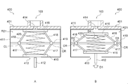
- FIG. 14A is a side sectional view showing a configuration example of the odor providing device 400 according to this embodiment.
- 14B is a side sectional view showing an operation example of the odor providing device 400.
- the odor providing device 400 differs from the odor providing device 100 according to the first embodiment in that one housing of the cartridge is provided with a mechanism for opening and closing two openings. Other configurations of the odor providing device 400 are the same as those of the odor providing device 100 .
- an odor providing device 400 includes a cylindrical cartridge 401 having flat front and rear surfaces. Further, similarly to the odor providing device 100 according to the first embodiment, the odor providing device 400 has a cylindrical driving mechanism 102 and a cartridge 401 formed at the tip of the cartridge 401 to release odor-containing air containing odor components to the outside. and a discharge hole 103 for
- the cartridge 401 includes a first housing 411 connected to a connecting portion 210 detachably connecting to the drive mechanism portion 102 that drives the movable portion.
- the connecting portion 210 of the cartridge 401 has a first shaft 412 as an operating shaft inside.
- the first shaft 412 is attached in front of the pusher 141 inside the drive mechanism section 102 .
- the first housing 411 has an internal space R21, and a first opening 413 and a second opening that open the internal space R21 to the outside and release odor-infused air, which is a mixture of odor components and air, toward the discharge hole 103. a portion 414 , a first sealing valve 415 that openably seals the first opening 413 , and a second sealing valve 416 that openably seals the second opening 414 .
- the first housing 411 includes two first struts 417 and two second struts 418 as movable parts that move the first sealing valve 415 and the second sealing valve 416, and the first struts 417 and and a strut operation rail 419 that is arranged between the second struts 418 and moves the first struts 417 and the second struts 418 in a direction that intersects the movable direction of the first sealing valve 415 and the second sealing valve 416, such as orthogonally.
- Both ends of the column operation rail 419 are fixed to the inner wall of the first housing 411 .
- the first housing 411 has a first spring 420 that biases the first sealing valve 415 and the second sealing valve 416 in a direction to bring them into close contact with the first opening 413 and the second opening 414 respectively during normal operation.
- an odor component retainer 130 such as an impregnating material that retains a liquid odor component is arranged surrounding the first spring 420, for example.
- Each of the two first struts 417 has one end connected to the first sealing valve 415 and the other end slidably contacts the strut operation rail 419 on the strut operation rail 419 .
- Each of the two second struts 418 has one end connected to the second sealing valve 416 and the other end slidably contacts the strut operation rail 419 on the strut operation rail 419 .
- the first pillar 417 and the second pillar 418 on the left side of the page of FIG. 14A are connected at their other ends by a connecting portion CL that is slidably mounted on a pillar operation rail 419 .
- the first support 417 and the second support 418 on the right side of the paper surface of FIG. 14A are connected at their other ends by a connecting portion CR that is slidably mounted on a support rail 419 for operating the support.
- the cartridge 401 is attached to the ends of the two first struts 417 and the two second struts 418 with the first spring 420 contracted when the first opening 413 and the second opening 414 are opened.
- the connecting portion CL and the connecting portion CR move away from each other on the column operation rail 419, the first sealing valve 415 and the second sealing valve 416 move toward each other in the internal space R21.
- the internal space R21 may be provided with a deodorizing agent 135 that deodorizes residual odor components after being discharged. good too.
- FIG. 14A is a side cross-sectional view showing a state where the opening of the odor providing device 400 is closed.
- FIG. 14B is a side cross-sectional view showing a state in which the opening of the odor providing device 400 is open.
- an air pump (not shown) connected to the air intake port of the drive mechanism housing portion 114 and supplied with air is turned on, and the air is introduced from the air pump. Air is sent into the interior of the drive mechanism housing portion 114 .
- This air pump is one aspect of a ventilation source, and is driven by power supplied from a battery of a primary battery or a secondary battery, and introduces air into the ventilation flow path.
- the shape memory alloy SMA connected to the pusher 141 when the shape memory alloy SMA connected to the pusher 141 is energized, the shape memory alloy SMA contracts from the pusher 141 toward the rear side. As a result, the pusher 141 is linearly moved to the front side of the odor providing device 400 .
- the first shaft 412 attached to the front of the pusher 141 also moves forward in the movable direction D1
- the first shaft 412 pushes the first sealing valve 415 forward
- the first sealing valve 415 moves in the movable direction. Move to D1.
- the first opening 413 sealed by the first sealing valve 415 opens to open the internal space R21 to the outside on the intake side.
- the air W sent into the drive mechanism accommodating portion 114 passes through the connecting portion 210 and flows from the first opening 413 into the internal space R21.
- the air W that has flowed into the internal space R21 is mixed with the odor components contained in the odor component retainer 130 provided in the internal space R21, and mixed odor-containing air W is produced.
- the connecting portion CL and the connecting portion CR attached to the ends of the two first struts 417 connected to the front of the first seal valve 415 move the struts. It is movable in a movable direction D2 and a movable direction D3 orthogonal to the movable direction D1 along the rail 419 for movement. That is, the first strut 417 moves in a direction in which the angle between the first strut 417 and the strut operation rail 419 becomes smaller.
- the connecting portion CL and the connecting portion CR move in the movable direction D2 and the movable direction D3, respectively, the ends of the two second columns 418 attached to the connecting portion CL and the connecting portion CR also move in the movable direction D2 and the movable direction D3, respectively. It moves in the movable direction D3. That is, the second strut 418 moves in a direction in which the angle between the second strut 418 and the strut operation rail 419 becomes smaller.
- the second sealing valve 416 connected to one end of the two second struts 418 moves rearward in the movable direction D4.
- the first spring 420 is compressed by being pressed from the first opening 413 and the second opening 414 in the direction of the column operation rail 419 at the center of the first housing 411 .
- the second sealing valve 416 moves toward the rear in the movable direction D4, the second opening 414 sealed by the second sealing valve 416 opens to open the internal space R21 to the outside on the exhaust side.
- the second opening 414 opens, the odor-laden air W mixed with the odor components in the internal space R21 flows into the discharge hole 103 from the second opening 414 .
- the scented air W that has flowed in from the second opening 414 is discharged from the discharge hole 103 to the user outside.
- the contracted state of the shape memory alloy SMA which is in the non-energized state is released, and the restoring force of the contracted first spring 420 causes the first shaft 412 to move. is pushed to its original position, the pusher 141 returns to its normal original position. Also, due to the restoring force of the first spring 420, the first sealing valve 415 and the second sealing valve 416 contact the first opening 413 and the first opening 231, respectively, and move in the movable direction D4 and the movable direction D1 until they are sealed. move in the direction of
- the odor providing device 400 including the cartridge 401 according to this embodiment can have the same effects as the odor providing device 100 according to the first embodiment. Furthermore, according to the odor providing device 400, the odor providing device 400 can be made thinner, and the structure can be effective for attachment to the XR/VR device.
- an examiner such as a doctor, nurse, or laboratory technician instructs the subject to display the examination procedure using an information processing device (S1).
- the information processing device, a storage unit, which will be described later, and the like may be provided in the odor providing device 100, or may be an external device connected via a wired or wireless network. Further, various devices having a user interface unit may be provided not only on the examiner's side but also on the side of the subject.
- the inspector determines the odor (olfactory element) to be emitted to the person to be inspected, and instructs the odor providing device 100 via the information processing device or the like. At this time, the odor providing device 100 that has received the instruction releases the odor from the cartridge 10 having the specific odor (S3).
- the information processing device or the like receives the response from the subject, and the storage unit stores the response (S5).
- the inspector determines whether or not to carry out the next inspection (S6), and if Yes, returns to step S2 to determine the next odor. In the case of No, the inspection is terminated as it is.
- the present technology can have the following configurations. (1) an internal space, a first opening and a second opening that open the internal space to the outside, and a movable part that can open and close at least one of the first opening and the second opening. , a plurality of housings arranged in a stack structure; an odor component holder disposed in an internal space of one of the plurality of housings and holding an odor component; with the first opening, the second opening, the movable part, and the odor component holder are arranged substantially parallel to the direction in which the plurality of housings are stacked; The movable part closes the first opening and/or the second opening when stationary, and opens the first opening and/or the second opening when the internal space is opened, and holds an odor component.
- the odor component holding member according to (1) further comprising a deodorant for deodorizing residual odor components in the internal space of any one of the plurality of housings.
- the odor component retaining member according to (1) or (2) wherein the deodorant is arranged at a position away from a ventilation channel of air passing through the internal space.
- the movable part has an operating shaft, a closing valve connected to an end of the operating shaft, and an elastic body biased in a closing direction of the first opening and/or the second opening. , the odor component retaining member according to any one of (1) to (3).
- the surface is made of a material selected from any one of low gas permeable resin, organic polymer, organic small molecule, organic metal, metal, metal film, or a combination of these ( The odor component retaining member according to any one of 1) to (14).
- odor component holding member according to any one of (1) to (16), wherein the odor component holding member is a cartridge attached to an odor providing device.
- the odor component holding member is a cartridge attached to an odor providing device.
- a plurality of housings arranged in a stack structure; an odor component holder disposed in an internal space of one of the plurality of housings and holding an odor component; an odor component holding member having a driving mechanism unit connected to the movable unit and driving the movable unit; with The first opening, the second opening, the movable part, and the odor component holding member are arranged substantially parallel to the direction in which the plurality of housings are stacked, The movable part closes the first opening and/or the second opening when stationary, and opens the first opening and/or the second opening when the internal space is open. . (19) An odor providing unit in which a plurality of odor providing devices according to (18) are arranged.
Landscapes
- Health & Medical Sciences (AREA)
- Epidemiology (AREA)
- Life Sciences & Earth Sciences (AREA)
- Animal Behavior & Ethology (AREA)
- General Health & Medical Sciences (AREA)
- Public Health (AREA)
- Veterinary Medicine (AREA)
- Engineering & Computer Science (AREA)
- Mechanical Engineering (AREA)
- Disinfection, Sterilisation Or Deodorisation Of Air (AREA)
Priority Applications (2)
| Application Number | Priority Date | Filing Date | Title |
|---|---|---|---|
| CN202280024076.0A CN117062632A (zh) | 2021-03-29 | 2022-02-18 | 气味成分保持部件、气味提供装置以及气味提供单元 |
| JP2023510641A JP7819690B2 (ja) | 2021-03-29 | 2022-02-18 | 匂い成分保持部材、匂い提供装置、および匂い提供ユニット |
Applications Claiming Priority (2)
| Application Number | Priority Date | Filing Date | Title |
|---|---|---|---|
| JP2021056159 | 2021-03-29 | ||
| JP2021-056159 | 2021-03-29 |
Publications (1)
| Publication Number | Publication Date |
|---|---|
| WO2022209406A1 true WO2022209406A1 (ja) | 2022-10-06 |
Family
ID=83455972
Family Applications (1)
| Application Number | Title | Priority Date | Filing Date |
|---|---|---|---|
| PCT/JP2022/006607 Ceased WO2022209406A1 (ja) | 2021-03-29 | 2022-02-18 | 匂い成分保持部材、匂い提供装置、および匂い提供ユニット |
Country Status (3)
| Country | Link |
|---|---|
| JP (1) | JP7819690B2 (https=) |
| CN (1) | CN117062632A (https=) |
| WO (1) | WO2022209406A1 (https=) |
Cited By (1)
| Publication number | Priority date | Publication date | Assignee | Title |
|---|---|---|---|---|
| WO2025225050A1 (ja) * | 2024-04-26 | 2025-10-30 | ソニーグループ株式会社 | 揮発性有機分子提示用カートリッジ及び揮発性有機分子提示システム |
Citations (9)
| Publication number | Priority date | Publication date | Assignee | Title |
|---|---|---|---|---|
| JPS62217967A (ja) * | 1985-10-31 | 1987-09-25 | 日東工器株式会社 | 芳香脱臭器 |
| JPS6451445U (https=) * | 1987-09-26 | 1989-03-30 | ||
| JPH08504606A (ja) * | 1991-10-30 | 1996-05-21 | ヴィテク、ゲッツ−ウルリッヒ | 映画上演等に際し事象又はシーンに応じて香を供給するための方法及び装置 |
| US5591409A (en) * | 1995-08-15 | 1997-01-07 | Watkins; Carl J. | Providing aromas |
| JP3062438U (ja) * | 1999-02-03 | 1999-10-08 | 敦雄 鈴木 | 芳香拡散式ロ―ラ―形簡易清掃具 |
| JP2008526333A (ja) * | 2005-01-05 | 2008-07-24 | コンセプション エ バロリザション ドゥ ブルベ (セーベーベー) | 多種香気拡散機器 |
| EP2255858A1 (en) * | 2009-05-29 | 2010-12-01 | Flakt Woods Limited | Fragance dispenser |
| JP2014516659A (ja) * | 2011-05-10 | 2014-07-17 | フラウンホッファー−ゲゼルシャフト ツァ フェルダールング デァ アンゲヴァンテン フォアシュンク エー.ファオ | 制御可能な流体サンプル・ディスペンサおよびそれを用いた方法 |
| JP2018095317A (ja) * | 2016-10-13 | 2018-06-21 | ミツミ電機株式会社 | カートリッジおよび噴出装置 |
-
2022
- 2022-02-18 JP JP2023510641A patent/JP7819690B2/ja active Active
- 2022-02-18 CN CN202280024076.0A patent/CN117062632A/zh active Pending
- 2022-02-18 WO PCT/JP2022/006607 patent/WO2022209406A1/ja not_active Ceased
Patent Citations (9)
| Publication number | Priority date | Publication date | Assignee | Title |
|---|---|---|---|---|
| JPS62217967A (ja) * | 1985-10-31 | 1987-09-25 | 日東工器株式会社 | 芳香脱臭器 |
| JPS6451445U (https=) * | 1987-09-26 | 1989-03-30 | ||
| JPH08504606A (ja) * | 1991-10-30 | 1996-05-21 | ヴィテク、ゲッツ−ウルリッヒ | 映画上演等に際し事象又はシーンに応じて香を供給するための方法及び装置 |
| US5591409A (en) * | 1995-08-15 | 1997-01-07 | Watkins; Carl J. | Providing aromas |
| JP3062438U (ja) * | 1999-02-03 | 1999-10-08 | 敦雄 鈴木 | 芳香拡散式ロ―ラ―形簡易清掃具 |
| JP2008526333A (ja) * | 2005-01-05 | 2008-07-24 | コンセプション エ バロリザション ドゥ ブルベ (セーベーベー) | 多種香気拡散機器 |
| EP2255858A1 (en) * | 2009-05-29 | 2010-12-01 | Flakt Woods Limited | Fragance dispenser |
| JP2014516659A (ja) * | 2011-05-10 | 2014-07-17 | フラウンホッファー−ゲゼルシャフト ツァ フェルダールング デァ アンゲヴァンテン フォアシュンク エー.ファオ | 制御可能な流体サンプル・ディスペンサおよびそれを用いた方法 |
| JP2018095317A (ja) * | 2016-10-13 | 2018-06-21 | ミツミ電機株式会社 | カートリッジおよび噴出装置 |
Cited By (1)
| Publication number | Priority date | Publication date | Assignee | Title |
|---|---|---|---|---|
| WO2025225050A1 (ja) * | 2024-04-26 | 2025-10-30 | ソニーグループ株式会社 | 揮発性有機分子提示用カートリッジ及び揮発性有機分子提示システム |
Also Published As
| Publication number | Publication date |
|---|---|
| JPWO2022209406A1 (https=) | 2022-10-06 |
| JP7819690B2 (ja) | 2026-02-25 |
| CN117062632A (zh) | 2023-11-14 |
Similar Documents
| Publication | Publication Date | Title |
|---|---|---|
| US8090244B2 (en) | Volatile material dispenser | |
| ES2634539T3 (es) | Dispositivo para terapia por inhalación | |
| JP5288573B1 (ja) | 嗅覚ディスプレイおよびそれに用いる香源カートリッジ | |
| US8196574B2 (en) | Nose mask | |
| WO2022209406A1 (ja) | 匂い成分保持部材、匂い提供装置、および匂い提供ユニット | |
| CN1933722A (zh) | 易挥发物质的受控释放 | |
| US11612672B2 (en) | Wireless electromechanical device for demonstrating multiple fragrances or aromas | |
| JP6150273B2 (ja) | 嗅覚ディスプレイ | |
| Zhang et al. | Subtle changes in lipid environment have profound effects on membrane oxidation chemistry | |
| JP7484881B2 (ja) | 香り提供装置 | |
| GB2560571A (en) | Automotive fragrance system | |
| WO2001081907A1 (en) | Method and apparatus for measurement, and method and apparatus for exposure | |
| WO2024116457A1 (ja) | 匂い提示モジュール、匂い提示システム、情報処理装置、及び匂い提示モジュール制御システム | |
| CN117120345B (zh) | 香料保持部件及香味提供装置 | |
| WO2023238421A1 (ja) | 匂い発生装置用カートリッジ、匂い発生装置、及び嗅覚検査装置 | |
| JP6265111B2 (ja) | 車両用機能性成分の保管供給装置およびそのカートリッジ | |
| US11344647B2 (en) | Wireless electromechanical device for controlled release of fragrances and scents | |
| US12427220B2 (en) | Perfume holding member and fragrance providing device | |
| WO2025225050A1 (ja) | 揮発性有機分子提示用カートリッジ及び揮発性有機分子提示システム | |
| US20250235574A1 (en) | Equipment for combining and diffusing multiple fragrances or aromas and the like | |
| JP6863320B2 (ja) | 揮発成分放出装置 | |
| TW202608490A (zh) | 揮發性有機分子提示用匣及揮發性有機分子提示系統 | |
| JP2004267512A (ja) | 香気装置 | |
| WO2024195148A1 (ja) | 直動アクチュエータ | |
| JP2018011802A (ja) | 芳香発生装置 |
Legal Events
| Date | Code | Title | Description |
|---|---|---|---|
| 121 | Ep: the epo has been informed by wipo that ep was designated in this application |
Ref document number: 22779633 Country of ref document: EP Kind code of ref document: A1 |
|
| WWE | Wipo information: entry into national phase |
Ref document number: 2023510641 Country of ref document: JP |
|
| WWE | Wipo information: entry into national phase |
Ref document number: 202280024076.0 Country of ref document: CN |
|
| NENP | Non-entry into the national phase |
Ref country code: DE |
|
| 122 | Ep: pct application non-entry in european phase |
Ref document number: 22779633 Country of ref document: EP Kind code of ref document: A1 |