WO2022209337A1 - 撮像レンズおよび撮像装置 - Google Patents
撮像レンズおよび撮像装置 Download PDFInfo
- Publication number
- WO2022209337A1 WO2022209337A1 PCT/JP2022/005198 JP2022005198W WO2022209337A1 WO 2022209337 A1 WO2022209337 A1 WO 2022209337A1 JP 2022005198 W JP2022005198 W JP 2022005198W WO 2022209337 A1 WO2022209337 A1 WO 2022209337A1
- Authority
- WO
- WIPO (PCT)
- Prior art keywords
- lens
- image
- imaging
- lens group
- imaging lens
- Prior art date
- Legal status (The legal status is an assumption and is not a legal conclusion. Google has not performed a legal analysis and makes no representation as to the accuracy of the status listed.)
- Ceased
Links
Images








Classifications
-
- G—PHYSICS
- G02—OPTICS
- G02B—OPTICAL ELEMENTS, SYSTEMS OR APPARATUS
- G02B13/00—Optical objectives specially designed for the purposes specified below
- G02B13/001—Miniaturised objectives for electronic devices, e.g. portable telephones, webcams, PDAs, small digital cameras
- G02B13/0015—Miniaturised objectives for electronic devices, e.g. portable telephones, webcams, PDAs, small digital cameras characterised by the lens design
- G02B13/002—Miniaturised objectives for electronic devices, e.g. portable telephones, webcams, PDAs, small digital cameras characterised by the lens design having at least one aspherical surface
- G02B13/0045—Miniaturised objectives for electronic devices, e.g. portable telephones, webcams, PDAs, small digital cameras characterised by the lens design having at least one aspherical surface having five or more lenses
-
- G—PHYSICS
- G02—OPTICS
- G02B—OPTICAL ELEMENTS, SYSTEMS OR APPARATUS
- G02B13/00—Optical objectives specially designed for the purposes specified below
-
- G—PHYSICS
- G02—OPTICS
- G02B—OPTICAL ELEMENTS, SYSTEMS OR APPARATUS
- G02B13/00—Optical objectives specially designed for the purposes specified below
- G02B13/18—Optical objectives specially designed for the purposes specified below with lenses having one or more non-spherical faces, e.g. for reducing geometrical aberration
-
- G—PHYSICS
- G02—OPTICS
- G02B—OPTICAL ELEMENTS, SYSTEMS OR APPARATUS
- G02B9/00—Optical objectives characterised both by the number of the components and their arrangements according to their sign, i.e. + or -
- G02B9/64—Optical objectives characterised both by the number of the components and their arrangements according to their sign, i.e. + or - having more than six components
-
- H—ELECTRICITY
- H04—ELECTRIC COMMUNICATION TECHNIQUE
- H04N—PICTORIAL COMMUNICATION, e.g. TELEVISION
- H04N23/00—Cameras or camera modules comprising electronic image sensors; Control thereof
- H04N23/95—Computational photography systems, e.g. light-field imaging systems
- H04N23/951—Computational photography systems, e.g. light-field imaging systems by using two or more images to influence resolution, frame rate or aspect ratio
-
- G—PHYSICS
- G02—OPTICS
- G02B—OPTICAL ELEMENTS, SYSTEMS OR APPARATUS
- G02B27/00—Optical systems or apparatus not provided for by any of the groups G02B1/00 - G02B26/00, G02B30/00
- G02B27/64—Imaging systems using optical elements for stabilisation of the lateral and angular position of the image
- G02B27/646—Imaging systems using optical elements for stabilisation of the lateral and angular position of the image compensating for small deviations, e.g. due to vibration or shake
Definitions
- the present disclosure has been made in view of the circumstances described above, and aims to provide an imaging lens that is compact and lightweight and has excellent optical performance, and an imaging apparatus that includes this imaging lens.
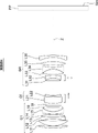
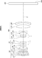
- FIG. 2 is a cross-sectional view showing the configuration and light flux of an imaging lens according to an embodiment, corresponding to the imaging lens of Example 1.
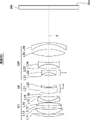
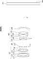
- FIG. 2 is a cross-sectional view showing the configuration of the imaging lens of Example 1.
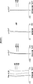
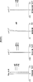
- FIG. 4A and 4B are aberration diagrams of the imaging lens of Example 1.
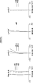
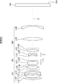
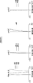
- FIG. 8 is a cross-sectional view showing the configuration of an imaging lens of Example 2; 10A and 10B are aberration diagrams of the imaging lens of Example 2.
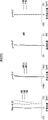
- FIG. FIG. 11 is a cross-sectional view showing the configuration of an imaging lens of Example 3; 10A to 10C are aberration diagrams of the imaging lens of Example 3.
- FIG. FIG. 11 is a cross-sectional view showing the configuration of an imaging lens of Example 4; FIG.
- the imaging lens more preferably satisfies the following conditional expression (11-1), and even more preferably satisfies the following conditional expression (11-2).
- conditional expression (11-1) 0.5 ⁇ Bf/Ymax ⁇ 1.7 (11-1) 0.8 ⁇ Bf/Ymax ⁇ 1.4 (11-2)
- conditional expression that the imaging lens of the present disclosure preferably satisfies is not limited to the conditional expression described in the form of an expression, and from among the conditional expressions that are preferable, more preferable, and even more preferable, the lower limit and It includes all conditional expressions obtained by arbitrarily combining with the upper limit.
- the surface numbers of the aspherical surfaces are marked with an asterisk (*), and the paraxial radius of curvature is described in the column for the radius of curvature of the aspherical surfaces.
- Table 13 the surface numbers of the aspherical surfaces are shown in the Sn row, and the aspherical coefficient values for each aspherical surface are shown in the KA and Am rows.
- "E ⁇ n" (n: integer) in the numerical values of the aspheric coefficients in Table 13 means " ⁇ 10 ⁇ n ".
- KA and Am are aspherical coefficients in the aspherical formula given below.
- FIG. 14 shows a cross-sectional view of the configuration of the imaging lens of Example 7.
- the imaging lens of Example 7 comprises, in order from the object side to the image side, a first lens group G1, a focus lens group Gf, and a rear lens group GR.
- the entire focus lens group Gf moves integrally toward the image side, and the first lens group G1 and the rear lens group GR are fixed with respect to the image plane Sim. It is
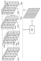
- the camera 30 includes a processor (not shown) that executes various processes such as image processing and output processing within the camera body 31 .
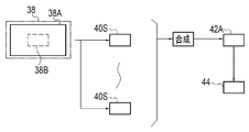
- the processor processes the captured image signal output from the imaging device 38 .
- the processor executes image correction processing and synthesis processing for synthesizing a plurality of captured images to create a synthetic image.
- the processor creates an image for storage based on the captured image and the synthesized image, and executes an output process of recording the created image for storage in a recording medium such as a memory card.
- the processor creates a display image based on the captured image and the synthesized image, and executes output processing for displaying the created display image on the display unit 36 .
Landscapes
- Physics & Mathematics (AREA)
- General Physics & Mathematics (AREA)
- Optics & Photonics (AREA)
- Engineering & Computer Science (AREA)
- Computing Systems (AREA)
- Theoretical Computer Science (AREA)
- Multimedia (AREA)
- Signal Processing (AREA)
- Lenses (AREA)
Abstract
Description
最大像高をYmax、
無限遠物体に合焦した状態における全系の焦点距離をf、
無限遠物体に合焦した状態における第1レンズ群の最も物体側のレンズ面から全系の最も像側のレンズ面までの光軸上の距離と空気換算距離でのバックフォーカスとの和をTLとした場合、
0.1<Ymax/f<0.26 (1)
0.4<TL/f<1.1 (2)
で表される条件式(1)および(2)を満足する。
0.2<|Dst5/Dst10|<0.6 (3)
で表される条件式(3)を満足することが好ましい。
1.5<Pe/Ymax<3 (4)
で表される条件式(4)を満足することが好ましい。
-0.6<(Rf-Rr)/(Rf+Rr)<-0.1 (5)
で表される条件式(5)を満足することが好ましい。
0.03<(Rpr-Rf)/(Rpr+Rf)<0.4 (6)
で表される条件式(6)を満足することが好ましい。
12<νn<30 (7)
で表される条件式(7)を満足することが好ましい。
0.02<DG1/f<0.2 (8)
で表される条件式(8)を満足することが好ましい。
1.4<tanωi/tanω<3.6 (9)
で表される条件式(9)を満足することが好ましい。
0.2<φf/φr<1.5 (10)
で表される条件式(10)を満足することが好ましい。
0.4<Bf/Ymax<1.8 (11)
で表される条件式(11)を満足することが好ましい。
0.25<f1/f<0.5 (12)
で表される条件式(12)を満足することが好ましい。
-0.9<fR/f<-0.1 (13)
で表される条件式(13)を満足することが好ましい。
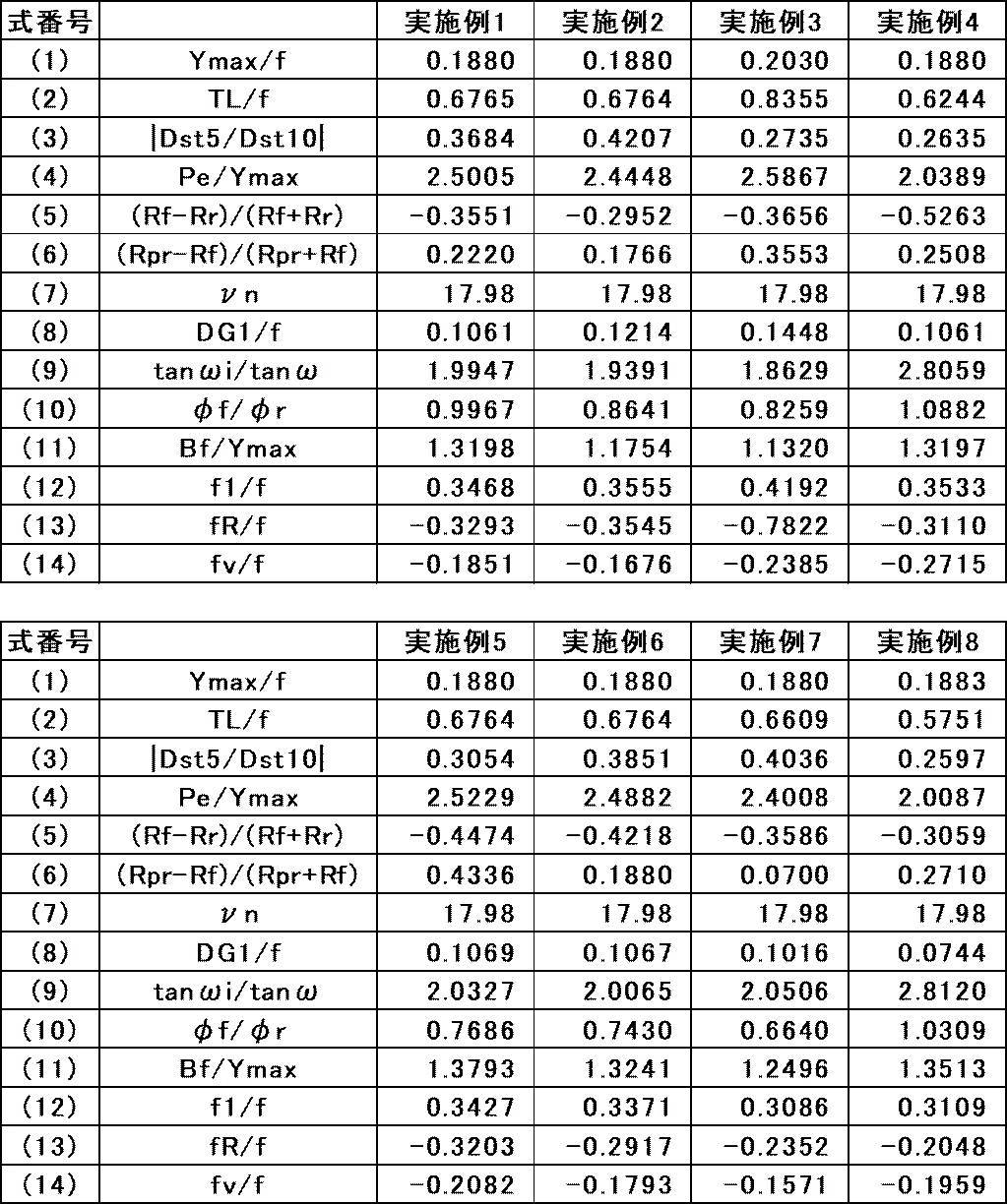
0.1<Ymax/f<0.26 (1)
0.12<Ymax/f<0.23 (1-1)
0.15<Ymax/f<0.21 (1-2)
0.4<TL/f<1.1 (2)
0.43<TL/f<0.92 (2-1)
0.5<TL/f<0.85 (2-2)
0.2<|Dst5/Dst10|<0.6 (3)
0.22<|Dst5/Dst10|<0.5 (3-1)
0.25<|Dst5/Dst10|<0.4 (3-2)
1.5<Pe/Ymax<3 (4)
1.6<Pe/Ymax<2.9 (4-1)
1.8<Pe/Ymax<2.7 (4-2)
-0.6<(Rf-Rr)/(Rf+Rr)<-0.1 (5)
-0.58<(Rf-Rr)/(Rf+Rr)<-0.17 (5-1)
-0.55<(Rf-Rr)/(Rf+Rr)<-0.25 (5-2)
0.03<(Rpr-Rf)/(Rpr+Rf)<0.4 (6)
0.04<(Rpr-Rf)/(Rpr+Rf)<0.32 (6-1)
0.07<(Rpr-Rf)/(Rpr+Rf)<0.27 (6-2)
12<νn<30 (7)
14<νn<25 (7-1)
17<νn<20 (7-2)
0.02<DG1/f<0.2 (8)
0.04<DG1/f<0.18 (8-1)
0.07<DG1/f<0.15 (8-2)
1.4<tanωi/tanω<3.6 (9)
1.5<tanωi/tanω<3.3 (9-1)
1.8<tanωi/tanω<2.9 (9-2)
0.2<φf/φr<1.5 (10)
0.3<φf/φr<1.4 (10-1)
0.6<φf/φr<1.13 (10-2)
0.4<Bf/Ymax<1.8 (11)
0.5<Bf/Ymax<1.7 (11-1)
0.8<Bf/Ymax<1.4 (11-2)
0.25<f1/f<0.5 (12)
0.27<f1/f<0.48 (12-1)
0.3<f1/f<0.45 (12-2)
-0.9<fR/f<-0.1 (13)
-0.8<fR/f<-0.15 (13-1)
-0.4<fR/f<-0.18 (13-2)
-0.35<fv/f<-0.1 (14)
-0.33<fv/f<-0.12 (14-1)
-0.3<fv/f<-0.15 (14-2)
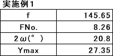
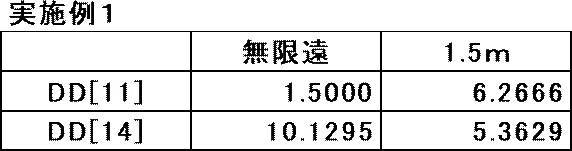
実施例1の撮像レンズの構成の断面図を図2に示す。実施例1の撮像レンズは、物体側から像側へ順に、第1レンズ群G1と、フォーカスレンズ群Gfと、後側レンズ群GRとからなる。無限遠物体から至近距離物体への合焦の際に、フォーカスレンズ群Gf全体が一体的に像側へ移動し、かつ第1レンズ群G1および後側レンズ群GRは像面Simに対して固定されている。

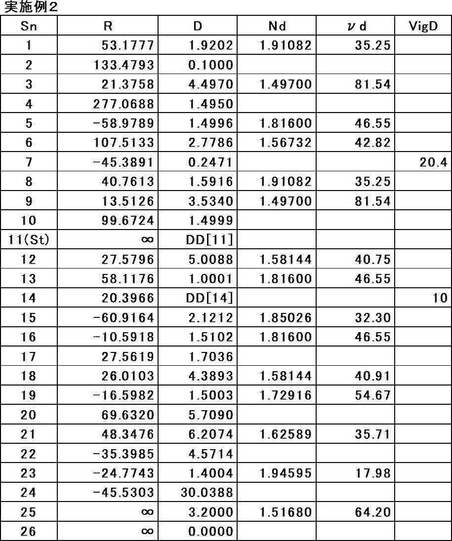
実施例2の撮像レンズの構成の断面図を図4に示す。実施例2の撮像レンズは、物体側から像側へ順に、第1レンズ群G1と、フォーカスレンズ群Gfと、後側レンズ群GRとからなる。無限遠物体から至近距離物体への合焦の際に、フォーカスレンズ群Gf全体が一体的に像側へ移動し、かつ第1レンズ群G1および後側レンズ群GRは像面Simに対して固定されている。


実施例3の撮像レンズの構成の断面図を図6に示す。実施例3の撮像レンズは、物体側から像側へ順に、第1レンズ群G1と、フォーカスレンズ群Gfと、後側レンズ群GRとからなる。無限遠物体から至近距離物体への合焦の際に、フォーカスレンズ群Gf全体が一体的に像側へ移動し、かつ第1レンズ群G1および後側レンズ群GRは像面Simに対して固定されている。


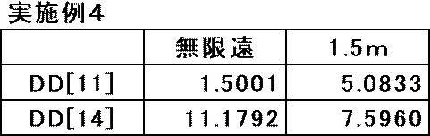
実施例4の撮像レンズの構成の断面図を図8に示す。実施例4の撮像レンズは、物体側から像側へ順に、第1レンズ群G1と、フォーカスレンズ群Gfと、後側レンズ群GRとからなる。無限遠物体から至近距離物体への合焦の際に、フォーカスレンズ群Gf全体が一体的に像側へ移動し、かつ第1レンズ群G1および後側レンズ群GRは像面Simに対して固定されている。
Zd=C×h2/{1+(1-KA×C2×h2)1/2}+ΣAm×hm
ただし、
Zd:非球面深さ(高さhの非球面上の点から、非球面頂点が接する光軸Zに垂直な平面に下ろした垂線の長さ)
h:高さ(光軸Zからレンズ面までの距離)
C:近軸曲率半径の逆数
KA、Am:非球面係数
であり、非球面式のΣはmに関する総和を意味する。非球面係数に関する記号、意味、および記載方法は、特に断りが無い限り以下の実施例においても同様である。



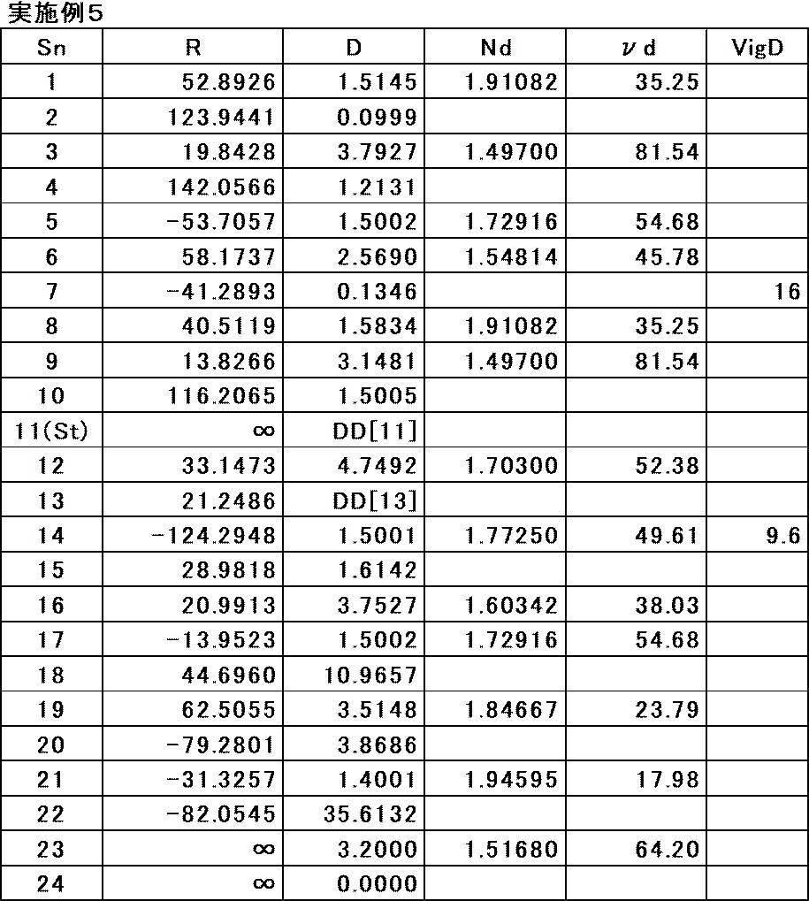
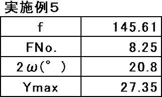
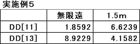
実施例5の撮像レンズの構成の断面図を図10に示す。実施例5の撮像レンズは、物体側から像側へ順に、第1レンズ群G1と、フォーカスレンズ群Gfと、後側レンズ群GRとからなる。無限遠物体から至近距離物体への合焦の際に、フォーカスレンズ群Gf全体が一体的に像側へ移動し、かつ第1レンズ群G1および後側レンズ群GRは像面Simに対して固定されている。
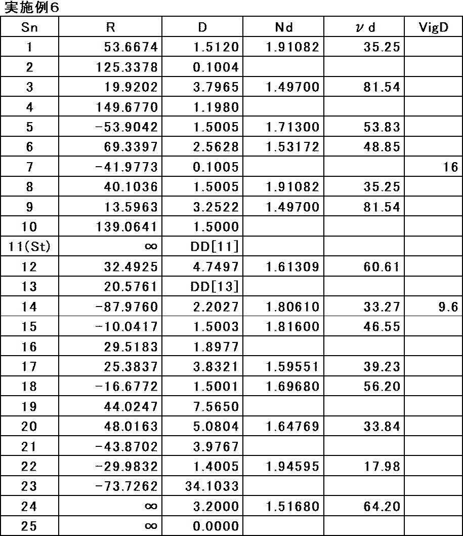
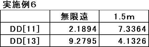
実施例6の撮像レンズの構成の断面図を図12に示す。実施例6の撮像レンズは、物体側から像側へ順に、第1レンズ群G1と、フォーカスレンズ群Gfと、後側レンズ群GRとからなる。無限遠物体から至近距離物体への合焦の際に、フォーカスレンズ群Gf全体が一体的に像側へ移動し、かつ第1レンズ群G1および後側レンズ群GRは像面Simに対して固定されている。

実施例7の撮像レンズの構成の断面図を図14に示す。実施例7の撮像レンズは、物体側から像側へ順に、第1レンズ群G1と、フォーカスレンズ群Gfと、後側レンズ群GRとからなる。無限遠物体から至近距離物体への合焦の際に、フォーカスレンズ群Gf全体が一体的に像側へ移動し、かつ第1レンズ群G1および後側レンズ群GRは像面Simに対して固定されている。


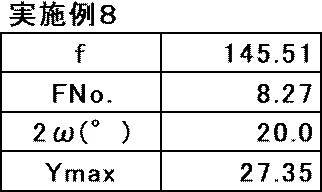
実施例8の撮像レンズの構成の断面図を図16に示す。実施例8の撮像レンズは、物体側から像側へ順に、第1レンズ群G1と、フォーカスレンズ群Gfと、後側レンズ群GRとからなる。無限遠物体から至近距離物体への合焦の際に、フォーカスレンズ群Gf全体が一体的に像側へ移動し、かつ第1レンズ群G1および後側レンズ群GRは像面Simに対して固定されている。



Claims (19)
- 最も物体側から像側へ順に連続して、合焦の際に像面に対して固定されている第1レンズ群と、合焦の際に光軸に沿って移動するフォーカスレンズ群とを含み、
最大像高をYmax、
無限遠物体に合焦した状態における全系の焦点距離をf、
無限遠物体に合焦した状態における前記第1レンズ群の最も物体側のレンズ面から全系の最も像側のレンズ面までの光軸上の距離と空気換算距離でのバックフォーカスとの和をTLとした場合、
0.1<Ymax/f<0.26 (1)
0.4<TL/f<1.1 (2)
で表される条件式(1)および(2)を満足する撮像レンズ。 - 無限遠物体に合焦した状態における最大像高の5割の像高での歪曲収差量をDst5、
無限遠物体に合焦した状態における最大像高での歪曲収差量をDst10とした場合、
0.2<|Dst5/Dst10|<0.6 (3)
で表される条件式(3)を満足する請求項1に記載の撮像レンズ。 - 無限遠物体に合焦した状態における像面から射出瞳位置までの光軸上の距離をPe、
Peの符号は、前記像面より前記射出瞳位置が物体側にあれば正、前記像面より前記射出瞳位置が像側にあれば負とした場合、
1.5<Pe/Ymax<3 (4)
で表される条件式(4)を満足する請求項1又は2に記載の撮像レンズ。 - 最も像側に負レンズを含み、
前記負レンズの物体側の面の曲率半径をRf、
前記負レンズの像側の面の曲率半径をRrとした場合、
-0.6<(Rf-Rr)/(Rf+Rr)<-0.1 (5)
で表される条件式(5)を満足する請求項1から3のいずれか1項に記載の撮像レンズ。 - 前記負レンズの物体側に前記負レンズに連続して正レンズを含み、
前記正レンズの像側の面の曲率半径をRprとした場合、
0.03<(Rpr-Rf)/(Rpr+Rf)<0.4 (6)
で表される条件式(6)を満足する請求項4に記載の撮像レンズ。 - 前記負レンズのd線基準のアッベ数をνnとした場合、
12<νn<30 (7)
で表される条件式(7)を満足する請求項4又は5に記載の撮像レンズ。 - 前記第1レンズ群の最も物体側のレンズ面から前記第1レンズ群の最も像側のレンズ面までの光軸上の距離をDG1とした場合、
0.02<DG1/f<0.2 (8)
で表される条件式(8)を満足する請求項1から6のいずれか1項に記載の撮像レンズ。 - 無限遠物体に合焦した状態における最大半画角をω、
無限遠物体に合焦した状態における最も像側のレンズから像面へ向かう最大像高の主光線と光軸に平行な軸との角度をωiとした場合、
1.4<tanωi/tanω<3.6 (9)
で表される条件式(9)を満足する請求項1から7のいずれか1項に記載の撮像レンズ。 - 前記第1レンズ群の最も物体側のレンズ面の最大有効径をφf、
全系の最も像側のレンズ面の最大有効径をφrとした場合、
0.2<φf/φr<1.5 (10)
で表される条件式(10)を満足する請求項1から8のいずれか1項に記載の撮像レンズ。 - 無限遠物体に合焦した状態における空気換算距離でのバックフォーカスをBfとした場合、
0.4<Bf/Ymax<1.8 (11)
で表される条件式(11)を満足する請求項1から9のいずれか1項に記載の撮像レンズ。 - 前記フォーカスレンズ群は全体として負の屈折力を有する請求項1から10のいずれか1項に記載の撮像レンズ。
- 前記フォーカスレンズ群が含むレンズの枚数は2枚以下である請求項11に記載の撮像レンズ。
- 前記第1レンズ群の焦点距離をf1とした場合、
0.25<f1/f<0.5 (12)
で表される条件式(12)を満足する請求項1から12のいずれか1項に記載の撮像レンズ。 - 物体側から像側へ順に、前記第1レンズ群と、全体として負の屈折力を有する前記フォーカスレンズ群と、合焦の際に像面に対して固定されている後側レンズ群とからなり、
前記後側レンズ群の焦点距離をfRとした場合、
-0.9<fR/f<-0.1 (13)
で表される条件式(13)を満足する請求項1から13のいずれか1項に記載の撮像レンズ。 - 撮像装置に設けられる前記撮像レンズであって、
前記撮像装置は、前記撮像レンズによって形成される光学像を撮像する撮像素子を備えており、前記撮像素子の最大撮像画角より狭い画角の画像を出力することが可能な請求項1および3から14のいずれか1項に記載の撮像レンズ。 - 撮像装置に設けられる前記撮像レンズであって、
前記撮像装置は、前記撮像レンズによって形成される光学像を撮像する撮像素子を備えており、前記撮像素子の最大撮像画角より狭い画角の画像を出力することが可能な請求項2に記載の撮像レンズ。 - 前記撮像装置は、前記撮像素子によって撮像された複数の画像を合成した合成画像を用いて、前記撮像素子の最大撮像画角より狭い画角の画像を出力することが可能な請求項16に記載の撮像レンズ。
- 撮像装置に設けられる前記撮像レンズであって、
前記撮像装置は、前記撮像レンズによって形成される光学像を撮像する撮像素子を備えており、前記撮像素子によって撮像された複数の画像を合成した合成画像を用いて、前記撮像素子の最大撮像画角より狭い画角の画像を出力することが可能な請求項1から15のいずれか1項に記載の撮像レンズ。 - 請求項1から18のいずれか1項に記載の撮像レンズを備えた撮像装置。
Priority Applications (3)
| Application Number | Priority Date | Filing Date | Title |
|---|---|---|---|
| JP2023510598A JP7758727B2 (ja) | 2021-03-29 | 2022-02-09 | 撮像レンズおよび撮像装置 |
| CN202280025234.4A CN117083553A (zh) | 2021-03-29 | 2022-02-09 | 成像镜头及摄像装置 |
| US18/470,035 US12601898B2 (en) | 2021-03-29 | 2023-09-19 | Imaging lens and imaging apparatus |
Applications Claiming Priority (2)
| Application Number | Priority Date | Filing Date | Title |
|---|---|---|---|
| JP2021056174 | 2021-03-29 | ||
| JP2021-056174 | 2021-03-29 |
Related Child Applications (1)
| Application Number | Title | Priority Date | Filing Date |
|---|---|---|---|
| US18/470,035 Continuation US12601898B2 (en) | 2021-03-29 | 2023-09-19 | Imaging lens and imaging apparatus |
Publications (1)
| Publication Number | Publication Date |
|---|---|
| WO2022209337A1 true WO2022209337A1 (ja) | 2022-10-06 |
Family
ID=83455850
Family Applications (1)
| Application Number | Title | Priority Date | Filing Date |
|---|---|---|---|
| PCT/JP2022/005198 Ceased WO2022209337A1 (ja) | 2021-03-29 | 2022-02-09 | 撮像レンズおよび撮像装置 |
Country Status (4)
| Country | Link |
|---|---|
| US (1) | US12601898B2 (ja) |
| JP (1) | JP7758727B2 (ja) |
| CN (1) | CN117083553A (ja) |
| WO (1) | WO2022209337A1 (ja) |
Cited By (1)
| Publication number | Priority date | Publication date | Assignee | Title |
|---|---|---|---|---|
| JP2023000170A (ja) * | 2021-06-17 | 2023-01-04 | 株式会社シグマ | 結像光学系 |
Citations (3)
| Publication number | Priority date | Publication date | Assignee | Title |
|---|---|---|---|---|
| JP2015075509A (ja) * | 2013-10-07 | 2015-04-20 | 株式会社タムロン | 撮影レンズ及び撮影装置 |
| JP2016051100A (ja) * | 2014-09-01 | 2016-04-11 | リコー光学株式会社 | インナーフォーカス式望遠レンズ |
| JP2020181000A (ja) * | 2019-04-23 | 2020-11-05 | 株式会社タムロン | 撮影レンズ及び撮影装置 |
Family Cites Families (5)
| Publication number | Priority date | Publication date | Assignee | Title |
|---|---|---|---|---|
| JP5587225B2 (ja) * | 2011-03-09 | 2014-09-10 | キヤノン株式会社 | 撮影光学系及びそれを有する撮像装置 |
| JP5749629B2 (ja) | 2011-11-01 | 2015-07-15 | 株式会社タムロン | インナーフォーカス式望遠レンズ |
| JP6727092B2 (ja) | 2016-10-06 | 2020-07-22 | 富士フイルム株式会社 | 撮像レンズおよび撮像装置 |
| JP7171048B2 (ja) | 2019-03-25 | 2022-11-15 | 株式会社シグマ | 結像光学系 |
| JP7547083B2 (ja) * | 2019-08-06 | 2024-09-09 | キヤノン株式会社 | 光学系及び撮像装置 |
-
2022
- 2022-02-09 WO PCT/JP2022/005198 patent/WO2022209337A1/ja not_active Ceased
- 2022-02-09 JP JP2023510598A patent/JP7758727B2/ja active Active
- 2022-02-09 CN CN202280025234.4A patent/CN117083553A/zh active Pending
-
2023
- 2023-09-19 US US18/470,035 patent/US12601898B2/en active Active
Patent Citations (3)
| Publication number | Priority date | Publication date | Assignee | Title |
|---|---|---|---|---|
| JP2015075509A (ja) * | 2013-10-07 | 2015-04-20 | 株式会社タムロン | 撮影レンズ及び撮影装置 |
| JP2016051100A (ja) * | 2014-09-01 | 2016-04-11 | リコー光学株式会社 | インナーフォーカス式望遠レンズ |
| JP2020181000A (ja) * | 2019-04-23 | 2020-11-05 | 株式会社タムロン | 撮影レンズ及び撮影装置 |
Cited By (2)
| Publication number | Priority date | Publication date | Assignee | Title |
|---|---|---|---|---|
| JP2023000170A (ja) * | 2021-06-17 | 2023-01-04 | 株式会社シグマ | 結像光学系 |
| JP7630823B2 (ja) | 2021-06-17 | 2025-02-18 | 株式会社シグマ | 結像光学系 |
Also Published As
| Publication number | Publication date |
|---|---|
| CN117083553A (zh) | 2023-11-17 |
| US12601898B2 (en) | 2026-04-14 |
| JP7758727B2 (ja) | 2025-10-22 |
| US20240004167A1 (en) | 2024-01-04 |
| JPWO2022209337A1 (ja) | 2022-10-06 |
Similar Documents
| Publication | Publication Date | Title |
|---|---|---|
| CN110780417B (zh) | 成像透镜及摄像装置 | |
| US8724232B2 (en) | Zoom lens and photographing apparatus including the same | |
| JP2020034671A (ja) | 撮像レンズ及び撮像装置 | |
| JP7039956B2 (ja) | 結像レンズおよびカメラおよび携帯情報端末装置 | |
| JP6422836B2 (ja) | ズームレンズおよび撮像装置 | |
| JP2019152690A (ja) | 撮像レンズおよび撮像装置 | |
| JP7682643B2 (ja) | 撮像レンズおよび撮像装置 | |
| JP5718020B2 (ja) | ズームレンズ及び撮像装置 | |
| EP1394591B1 (en) | Zoom lens and image pickup apparatus | |
| JP2016164629A (ja) | ズームレンズおよび撮像装置 | |
| JP2019113609A (ja) | ズームレンズ及び撮像装置 | |
| JP2018146607A (ja) | 撮像レンズおよび撮像装置 | |
| WO2017169582A1 (ja) | ズームレンズおよび撮像装置 | |
| JP2019066694A (ja) | 変倍光学系及びそれを備えた撮像装置 | |
| JP7146708B2 (ja) | 撮像レンズおよび撮像装置 | |
| JP2016071141A (ja) | ズームレンズおよび撮像装置 | |
| JP2019113587A (ja) | ズームレンズ及び撮像装置 | |
| WO2017169583A1 (ja) | ズームレンズおよび撮像装置 | |
| JP2007256452A (ja) | ズームレンズ及びそれを用いた撮像装置 | |
| JP2023123216A (ja) | 撮像レンズおよび撮像装置 | |
| JP7758727B2 (ja) | 撮像レンズおよび撮像装置 | |
| JP2019152691A (ja) | 撮像レンズおよび撮像装置 | |
| JP2022016016A (ja) | 撮像レンズおよび撮像装置 | |
| JP2018146869A (ja) | ズームレンズおよび撮像装置 | |
| JP2011137875A (ja) | ズームレンズ及び撮像装置 |
Legal Events
| Date | Code | Title | Description |
|---|---|---|---|
| 121 | Ep: the epo has been informed by wipo that ep was designated in this application |
Ref document number: 22779566 Country of ref document: EP Kind code of ref document: A1 |
|
| ENP | Entry into the national phase |
Ref document number: 2023510598 Country of ref document: JP Kind code of ref document: A |
|
| WWE | Wipo information: entry into national phase |
Ref document number: 202280025234.4 Country of ref document: CN |
|
| NENP | Non-entry into the national phase |
Ref country code: DE |
|
| 122 | Ep: pct application non-entry in european phase |
Ref document number: 22779566 Country of ref document: EP Kind code of ref document: A1 |