WO2022209290A1 - 構造物の状態予測装置、方法及びプログラム - Google Patents
構造物の状態予測装置、方法及びプログラム Download PDFInfo
- Publication number
- WO2022209290A1 WO2022209290A1 PCT/JP2022/004503 JP2022004503W WO2022209290A1 WO 2022209290 A1 WO2022209290 A1 WO 2022209290A1 JP 2022004503 W JP2022004503 W JP 2022004503W WO 2022209290 A1 WO2022209290 A1 WO 2022209290A1
- Authority
- WO
- WIPO (PCT)
- Prior art keywords
- feature amount
- feature
- image
- combining
- prediction device
- Prior art date
- Legal status (The legal status is an assumption and is not a legal conclusion. Google has not performed a legal analysis and makes no representation as to the accuracy of the status listed.)
- Ceased
Links
Images




Classifications
-
- G—PHYSICS
- G06—COMPUTING OR CALCULATING; COUNTING
- G06Q—INFORMATION AND COMMUNICATION TECHNOLOGY [ICT] SPECIALLY ADAPTED FOR ADMINISTRATIVE, COMMERCIAL, FINANCIAL, MANAGERIAL OR SUPERVISORY PURPOSES; SYSTEMS OR METHODS SPECIALLY ADAPTED FOR ADMINISTRATIVE, COMMERCIAL, FINANCIAL, MANAGERIAL OR SUPERVISORY PURPOSES, NOT OTHERWISE PROVIDED FOR
- G06Q50/00—Information and communication technology [ICT] specially adapted for implementation of business processes of specific business sectors, e.g. utilities or tourism
- G06Q50/10—Services
- G06Q50/16—Real estate
- G06Q50/163—Real estate management
-
- G—PHYSICS
- G06—COMPUTING OR CALCULATING; COUNTING
- G06T—IMAGE DATA PROCESSING OR GENERATION, IN GENERAL
- G06T7/00—Image analysis
- G06T7/0002—Inspection of images, e.g. flaw detection
-
- G—PHYSICS
- G06—COMPUTING OR CALCULATING; COUNTING
- G06Q—INFORMATION AND COMMUNICATION TECHNOLOGY [ICT] SPECIALLY ADAPTED FOR ADMINISTRATIVE, COMMERCIAL, FINANCIAL, MANAGERIAL OR SUPERVISORY PURPOSES; SYSTEMS OR METHODS SPECIALLY ADAPTED FOR ADMINISTRATIVE, COMMERCIAL, FINANCIAL, MANAGERIAL OR SUPERVISORY PURPOSES, NOT OTHERWISE PROVIDED FOR
- G06Q10/00—Administration; Management
- G06Q10/04—Forecasting or optimisation specially adapted for administrative or management purposes, e.g. linear programming or "cutting stock problem"
-
- G—PHYSICS
- G06—COMPUTING OR CALCULATING; COUNTING
- G06Q—INFORMATION AND COMMUNICATION TECHNOLOGY [ICT] SPECIALLY ADAPTED FOR ADMINISTRATIVE, COMMERCIAL, FINANCIAL, MANAGERIAL OR SUPERVISORY PURPOSES; SYSTEMS OR METHODS SPECIALLY ADAPTED FOR ADMINISTRATIVE, COMMERCIAL, FINANCIAL, MANAGERIAL OR SUPERVISORY PURPOSES, NOT OTHERWISE PROVIDED FOR
- G06Q10/00—Administration; Management
- G06Q10/10—Office automation; Time management
- G06Q10/103—Workflow collaboration or project management
-
- G—PHYSICS
- G06—COMPUTING OR CALCULATING; COUNTING
- G06Q—INFORMATION AND COMMUNICATION TECHNOLOGY [ICT] SPECIALLY ADAPTED FOR ADMINISTRATIVE, COMMERCIAL, FINANCIAL, MANAGERIAL OR SUPERVISORY PURPOSES; SYSTEMS OR METHODS SPECIALLY ADAPTED FOR ADMINISTRATIVE, COMMERCIAL, FINANCIAL, MANAGERIAL OR SUPERVISORY PURPOSES, NOT OTHERWISE PROVIDED FOR
- G06Q10/00—Administration; Management
- G06Q10/20—Administration of product repair or maintenance
-
- G—PHYSICS
- G06—COMPUTING OR CALCULATING; COUNTING
- G06Q—INFORMATION AND COMMUNICATION TECHNOLOGY [ICT] SPECIALLY ADAPTED FOR ADMINISTRATIVE, COMMERCIAL, FINANCIAL, MANAGERIAL OR SUPERVISORY PURPOSES; SYSTEMS OR METHODS SPECIALLY ADAPTED FOR ADMINISTRATIVE, COMMERCIAL, FINANCIAL, MANAGERIAL OR SUPERVISORY PURPOSES, NOT OTHERWISE PROVIDED FOR
- G06Q50/00—Information and communication technology [ICT] specially adapted for implementation of business processes of specific business sectors, e.g. utilities or tourism
- G06Q50/08—Construction
-
- G—PHYSICS
- G06—COMPUTING OR CALCULATING; COUNTING
- G06T—IMAGE DATA PROCESSING OR GENERATION, IN GENERAL
- G06T7/00—Image analysis
- G06T7/0002—Inspection of images, e.g. flaw detection
- G06T7/0004—Industrial image inspection
-
- G—PHYSICS
- G06—COMPUTING OR CALCULATING; COUNTING
- G06T—IMAGE DATA PROCESSING OR GENERATION, IN GENERAL
- G06T2207/00—Indexing scheme for image analysis or image enhancement
- G06T2207/10—Image acquisition modality
- G06T2207/10016—Video; Image sequence
-
- G—PHYSICS
- G06—COMPUTING OR CALCULATING; COUNTING
- G06T—IMAGE DATA PROCESSING OR GENERATION, IN GENERAL
- G06T2207/00—Indexing scheme for image analysis or image enhancement
- G06T2207/20—Special algorithmic details
- G06T2207/20084—Artificial neural networks [ANN]
-
- G—PHYSICS
- G06—COMPUTING OR CALCULATING; COUNTING
- G06T—IMAGE DATA PROCESSING OR GENERATION, IN GENERAL
- G06T2207/00—Indexing scheme for image analysis or image enhancement
- G06T2207/30—Subject of image; Context of image processing
- G06T2207/30108—Industrial image inspection
- G06T2207/30132—Masonry; Concrete
-
- G—PHYSICS
- G06—COMPUTING OR CALCULATING; COUNTING
- G06T—IMAGE DATA PROCESSING OR GENERATION, IN GENERAL
- G06T2207/00—Indexing scheme for image analysis or image enhancement
- G06T2207/30—Subject of image; Context of image processing
- G06T2207/30108—Industrial image inspection
- G06T2207/30136—Metal
-
- G—PHYSICS
- G06—COMPUTING OR CALCULATING; COUNTING
- G06T—IMAGE DATA PROCESSING OR GENERATION, IN GENERAL
- G06T2207/00—Indexing scheme for image analysis or image enhancement
- G06T2207/30—Subject of image; Context of image processing
- G06T2207/30181—Earth observation
- G06T2207/30184—Infrastructure
Definitions
- the present invention relates to a structure state prediction device, method, and program, and more particularly to technology for predicting the future state of a structure from multiple images (temporal images) taken of the structure at different times.
- Managers such as local governments formulate longevity plans and standardize budgets based on the prediction results of deterioration prediction formulas that treat the members of each structure (for example, bridges) as a group.
- Patent Document 1 damage information including a vectorized vector of damage extracted from an image of a structure is generated, and a progression model that shows the correspondence between the damage state and the degree of damage of the model structure is developed. Analyze at least the vector of the damage information of the structure, obtain the degree of damage of the structure corresponding to the damage state of the structure, and acquire each based on multiple images at different inspection times of the structure An information processing device is described that compares a plurality of degrees of damage and acquires the damage progression speed of a structure.
- the information processing device described in Patent Document 1 uses a database in which damage progression parameters that affect damage progression and inspection result information for a structure other than the structure to be inspected are stored in association with each other, and the damage progression parameters are retrieved from the database. Search the inspection result information of another structure that is the same or similar to the target structure, and use the retrieved inspection result information of the other structure to create a progress model corresponding to the damage progression parameters of the structure to be inspected. It has a progression model generator that generates
- the damage progression parameters that affect the progression of damage described in Patent Document 1 include natural environment information about the natural environment of the structure to be inspected, usage status information about the usage status of the structure, structural information about the structure of the structure, structure It includes at least one of material information about the material of the object, drug information about the drug applied to the structure, and maintenance performance information about the repair performance and reinforcement performance of the structure.
- Patent Literature 1 describes a technique for grasping the tendency of features in similar structures, for example, the tendency of progression speed of damage. However, this is not necessarily the case for structures to be inspected.
- the present invention has been made in view of such circumstances, and is a structure state prediction apparatus and method that can perform highly accurate deterioration prediction for individual structures for general purposes at a realistic cost. and to provide programs.
- the invention according to a first aspect provides a structure state prediction device comprising a processor, wherein the processor captures a first image of the structure and before the first image is captured.
- Data acquisition for selecting and acquiring time-lapse images and structure-related data related to deterioration of structures from a database that manages time-lapse images including the second image obtained and structure-related data that is data related to structures.
- a first feature amount calculation process of calculating a first feature amount including at least the degree of progress of damage to the structure from the temporal image; and a second feature amount calculation process of calculating a second feature amount related to the structure from the acquired structure-related data.
- the first feature amount including the progress of damage to the structure calculated from the time-lapse image and the second feature amount related to the structure calculated from the structure-related data are independent of each other.
- the future state of the structure is predicted based on a third feature amount obtained by combining (integrating) the first feature amount and the second feature amount.
- the third feature amount calculation process has a plurality of combining methods for combining the first feature amount and the second feature amount
- a third feature is obtained by combining the first feature and the second feature by a combination method selected from a plurality of combination methods according to the degree of contribution of the first feature and the second feature to predicting the state. It is preferred to calculate the amount.
- a method of combining the first feature amount and the second feature amount according to the degree of contribution of the first feature amount and the second feature amount to predicting the future state of the structure By selecting , different prediction models can be made according to the degree of contribution.
- the type of prediction processing includes two or more of soundness, remaining life, damage degree, and countermeasure classification
- third feature amount calculation processing has a plurality of combination methods for combining the first feature amount and the second feature amount, and according to the type of prediction processing, the first feature amount and the second feature amount are combined by a combination method selected from a plurality of combination methods are combined to calculate the third feature amount, and the prediction process predicts at least one of the structural soundness, remaining life, damage level, and countermeasure classification.
- the third aspect of the present invention by selecting the method of combining the first feature amount and the second feature amount according to the type of prediction processing, different prediction models can be used according to the type of prediction processing. can.
- the time-lapse image is an image obtained by photographing the same part or member of the structure
- the third feature amount calculation process includes the first feature amount and the second feature amount.
- Quantities are calculated and the prediction process predicts the condition of the parts or members of the structure.
- the fourth aspect of the present invention by selecting the method of combining the first feature amount and the second feature amount according to the type of the part or member, different prediction models are made according to the type of the part or member. be able to.
- the first image and the second image are preferably images captured during regular inspection of the structure. Since the regular inspection is performed at predetermined intervals, the interval between the first and second images can be matched with the regular inspection, and good time-lapse images can be obtained.
- the structure-related data includes specification data of the structure, weather data at the installation position of the structure, traffic data related to the structure, and inspection of the structure.
- the data is one or more of history, structure repair history, and reinforcement history.
- the first feature amount calculation process preferably calculates the first feature amount using a first neural network that has been trained by supervised learning.
- the second feature amount calculation process calculates the second feature amount by a second neural network that has been learned by supervised learning, or calculates the structure related data It is preferable to calculate the second feature amount by performing dimensional compression.
- the third feature amount calculation process connects the first feature amount and the second feature amount to calculate the third feature amount.
- the third feature amount calculation process preferably calculates the third feature amount by weighted sum of the first feature amount and the second feature amount.
- the third feature amount calculation process combines the first feature amount and the second feature amount by a third neural network to calculate the third feature amount. is preferred.
- the time-lapse images are images obtained by photographing the same part or member of the structure, and a plurality of time-lapse images obtained by photographing a plurality of parts or members of the structure. Including images, the prediction process preferably predicts the overall state of the structure.
- the temporal images preferably include three or more images having the first image and the second image.
- the processor outputs the predicted future state of the structure to a display or printer, or performs an output process to store it in a memory. This is to perform preventive maintenance of the structure according to the predicted future state of the structure.
- a fifteenth aspect of the invention provides time-lapse images including a first image of a structure and a second image captured before the first image is captured, and structure-related data, which is data about the structure.
- a sixteenth aspect of the invention provides time-lapse images including a first image of a structure and a second image captured before the first image is captured, and structure-related data that is data about the structure.
- FIG. 1 is a block diagram showing an embodiment of a hardware configuration of a structure state prediction apparatus according to the present invention.
- FIG. 2 is a functional block diagram showing the first embodiment of the structure state prediction device according to the present invention.
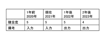
- FIG. 3 is a table showing an output image of prediction results from the structure state prediction device.
- FIG. 4 is a graph showing an output image of prediction results from the structure state prediction device.
- FIG. 5 is another graph showing an output image of the prediction result by the structure state prediction device.
- FIG. 6 is still another graph showing an output image of the prediction result by the structure state prediction device.
- FIG. 7 is a functional block diagram showing a second embodiment of the structure state prediction device according to the present invention.
- FIG. 8 is a functional block diagram showing a third embodiment of a structure state prediction device according to the present invention.
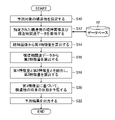
- FIG. 9 is a flow chart showing an embodiment of a structure state prediction method according to the present invention.
- FIG. 1 is a block diagram showing an embodiment of a hardware configuration of a structure state prediction device according to the present invention.
- the structure state prediction device 1 is provided for the maintenance and management of structures such as bridges, tunnels, and dams, and predicts the future state of the structures to be managed.
- This structure state prediction apparatus 1 is composed of a personal computer, a workstation, etc., and includes a processor 10, a memory 11, a database 12, a display unit (display) 14, an input/output interface 16, an operation unit 18, and the like.
- the processor 10 is composed of a CPU (Central Processing Unit) and the like, and controls each part of the structure state prediction device 1.
- the data acquisition part 20 shown in FIG. It functions as a two-feature amount calculator 24 , a feature amount combiner 26 and a prediction processor 28 .
- the memory 11 includes flash memory, ROM (Read-only Memory), RAM (Random Access Memory), hard disk device, and the like.
- the flash memory, ROM, or hard disk device is a non-volatile memory that stores an operating system, various programs including a structure state prediction program according to the present invention, and the like.
- the RAM functions as a working area for processing by the processor 10 . It also temporarily stores a structure state prediction program stored in a flash memory or the like. Note that the processor 10 may incorporate part of the memory 11 (RAM).
- the database 12 stores and manages time-lapse images including a first image of a structure and a second image captured before the first image, and structure-related data, which is data related to the structure. , and stores and manages temporal images and structure-related data for each structure to be managed.
- the database 12 may be included in the structure state prediction device 1 or may be provided outside the structure state prediction device 1 separately. Further, the database 12 is not limited to one database, and may be composed of a plurality of databases that are separately managed according to storage management contents such as temporal images and structure-related data.
- the processor 10 acquires necessary data such as temporal images and structure-related data from the database 12 while using the RAM as a work area according to the structure state prediction program, and controls each part of the structure state prediction device 1. and processing.
- the display unit 14 displays the future state of the structure predicted by the processor 10. By confirming the future state of the structure displayed on the display unit 14, the user can perform appropriate preventive maintenance, formulation of life extension plans, and the like for the structure. Note that the display unit 14 is also used as part of a GUI (Graphical User Interface) when receiving an instruction, etc. of a structure to be predicted from the operation unit 18 .
- GUI Graphic User Interface
- the input/output interface 16 includes a connection that can be connected to an external device, a communication unit that can be connected to a network, and the like.
- USB Universal Serial Bus
- HDMI High-Definition Multimedia Interface
- HDMI High-Definition Multimedia Interface
- the processor 10 can acquire desired structure-related data and the like via the input/output interface 16 .
- an external display device connected to the input/output interface 16 can be used instead of the display unit 14, an external display device connected to the input/output interface 16 can be used.
- the operation unit 18 includes a keyboard, a pointing device such as a mouse, a keyboard, etc., and functions as part of a GUI that accepts various designations by the user.
- FIG. 2 is a functional block diagram showing the first embodiment of the structure state prediction device according to the present invention.
- the processor 10 of the structure state prediction device 1 having the hardware configuration shown in FIG. , a second feature quantity calculator 24 , a feature quantity combiner 26 and a prediction processor 28 .
- the data acquisition unit 20 When the data acquisition unit 20 receives the specification of the structure to be predicted from the GUI operated by the user, the data acquisition unit 20 acquires the time-lapse image of the specified structure and the structure-related data from the database 12. be.
- the database 12 is a part that stores and manages time-lapse images of structures and structure-related data for each structure. Specific examples of temporal images and structure-related data when the structure is a bridge will be described below.
- Time-lapse images are two or more images taken at different times, including a first image taken of a specific part of a structure (bridge) and a second image taken before the first image was taken.
- ⁇ Shooting interval 1 year, 5 years, etc.
- short-term shooting or recording may be performed (for example, at intervals of 1 day or 1 month).
- - Imaging condition The same part or member of the bridge is photographed.
- the time-lapse image for example, an image obtained by close-up photographing a specific part of the bridge during the annual periodic inspection of the bridge can be used.
- the photographing conditions may not all be strictly standardized. Therefore, the "same part or member” does not need to be strictly "same” as long as the corresponding part or member is included in the image.
- the structure-related data includes one or more of the specification data of the structure, weather data at the installation location of the structure, traffic data related to the structure, inspection history of the structure, repair history and reinforcement history of the structure. Data.
- ⁇ Bridge specification data construction year, position, construction type, type (girder bridge, rigid frame bridge, truss bridge, arch bridge, cable-stayed bridge, suspension bridge), material (steel, reinforced concrete, PC (Prestressed Concrete), etc.), drawings ( CAD: computer-aided design, etc.)
- CAD computer-aided design, etc.
- ⁇ Inspection history Damage type, soundness, remaining life, degree of damage, countermeasure category
- ⁇ Repair and reinforcement history Repair and reinforcement method
- ⁇ Weather data Rainfall, snowfall, river flow, wind direction/speed, airborne salt content
- Traffic volume per day, per month, per year, cumulative, etc.
- vehicle type load capacity
- ⁇ Others Inspection information (deflection of structures, amplitude of vibration of structures, period of vibration of structures (monitoring information such as monitoring information, etc.), data related to similar bridges. Varies accordingly.
- the data acquisition unit 20 may acquire part of the structure-related data from another database 13. For example, using the Geographic Information System (GIS), information on bridge geographic information (distance from the coastline) is obtained from the Geographical Survey Institute, and public data (precipitation, humidity, wind direction, wind speed) from the Japan Meteorological Agency are obtained. and public data (traffic data) of the Ministry of Land, Infrastructure, Transport and Tourism can be obtained.
- GIS Geographic Information System
- information on bridge geographic information is obtained from the Geographical Survey Institute
- public data precipitation, humidity, wind direction, wind speed
- public data traffic data of the Ministry of Land, Infrastructure, Transport and Tourism can be obtained.
- the temporal image acquired by the data acquisition unit 20 from the database 12 is output to the first feature amount calculation unit 22, and the structure-related data is output to the second feature amount calculation unit 24.
- the first feature quantity calculation unit 22 is a part that performs a first feature quantity calculation process for calculating a first feature quantity including at least the degree of progress of damage to a structure from the input time-lapse image.
- the first feature amount calculation unit 22 can be configured by a convolution neural network (CNN: Convolution Neural Network) or a recurrent neural network (RNN: Recurrent Neural Network), which is a first neural network that has been trained by supervised learning. can.
- CNN Convolution Neural Network
- RNN Recurrent Neural Network
- Degree of damage progress slight progress, progress, no progress, unknown progress
- ⁇ Degree of damage For example, 5-level evaluation based on the inspection manual of Nagasaki prefecture
- ⁇ Damage rate For example, 0%-100 based on the inspection manual of Nagasaki prefecture % (in units of 10%)
- ⁇ Damage area Segmentation that indicates the damaged location in units of pixels and/or polygons
- Image feature amount Intermediate feature amount of a trained model based on a large-scale image database of color photographs From each included image, calculate the first feature value including the progress of damage of the structure by CNN etc., or use CNN, RNN etc. to perform supervised learning of the first feature value indicating the entire deterioration prediction of the structure Earn from
- the second feature amount calculation unit 24 is a part that performs a second feature amount calculation process for calculating a second feature amount related to the future state of the structure from the input structure-related data.
- the second feature amount calculation unit 24 calculates the second feature amount from the data selected as data related to deterioration of the structure among the structure-related data. For example, for the time-series weather data, traffic data, etc. of the structure-related data, calculate the integrated value for the entire period, leave the specification data as it is, and use principal component analysis (PCA) etc. Dimensionally compressed to calculate the second feature quantity, or using RNN, etc., which is a second neural network that has been trained by supervised learning, to obtain the second feature quantity that indicates the entire deterioration prediction of the structure from supervised learning. do.
- PCA principal component analysis
- the feature values of the weather data included in the structure-related data are cumulative values, moving average values, maximum values, minimum values, etc.
- the feature amount combining unit 26 functioning as a third feature amount calculation processing unit combines the first feature amount calculated by the first feature amount calculation unit 22 and the second feature amount calculated by the second feature amount calculation unit 24.
- a third feature amount is calculated by combining.
- the feature quantity combining unit 26 has a plurality of combining methods for combining the first feature quantity and the second feature quantity, and combines the first feature quantity and the second feature quantity by a combining method selected from the plurality of combining methods. and calculate the third feature amount.
- the feature quantity combining unit 26 selects one of the above multiple combining methods such as "connection”, “weighted sum”, and “neural network”.
- the choice of binding method is (1) A method of selecting according to the contribution of the first feature amount and the second feature amount to the prediction of the future state of the structure (2) Type of prediction processing (structural soundness (soundness), (3) Method of selecting according to the type of structural part or member when predicting the state of the structural part or member. be done.
- connection and “weighted sum ', or 'neural network'.
- connection method may be selected accordingly, or the connection method may be automatically selected.
- connection method may be selected accordingly, or the connection method may be automatically selected.
- the feature quantity combining unit 26 calculates the third feature quantity by combining the first feature quantity and the second feature quantity by a combination method selected from a plurality of combination methods as described above. Thereby, different prediction models can be set according to the degree of contribution of the first feature amount and the second feature amount, the type of prediction processing, or the type of the part or member of the structure.
- the prediction processing unit 28 performs prediction processing for predicting the future state of the structure based on the third feature quantity combined (calculated) by the feature quantity combining unit 26 .
- the prediction processing unit 28 can be configured by an RNN or the like, which is a fourth neural network that has been trained by supervised learning, at the same time as combining the feature amounts described above, and inputs the third feature amount from the feature amount combining unit 26. Then, a prediction result for one or more types of prediction processing among the structural soundness (soundness), remaining life, degree of damage, and countermeasure classification is output.
- the prediction processing unit 28 evaluates the future state of the structure, for example, on a scale of 1 to 5.
- the soundness can be predicted and the soundness after N years can be output.
- N is a natural number.
- the processor 10 (FIG. 1) performs output processing to output the future state of the structure predicted by the prediction processing unit 28 to the display unit 14 or a printer (not shown), or to store it in the memory 11 or the database 12.
- Fig. 3 is a diagram showing an output image of the prediction results from the structure state prediction device.
- time-lapse images and structure-related data of the present for example, 2021 and one year ago (2020) are input, and the state prediction device 1 of the structure predicts the health of the present and one year ago.
- the prediction results of the health degree one year later (2022) and two years later (2023) are output as a table.
- the present and one year ago soundness can use the inspection history included in the present and one year ago structure-related data.
- the soundness after one year is "5", which is the same as the soundness at present and one year ago, but the soundness after two years may drop to "4". I understand.
- 4 to 6 are graphs showing output images of prediction results from the structure state prediction device.
- the vertical axis of the graphs shown in Figures 4 to 6 indicates the soundness evaluation level
- the horizontal axis of the graph indicates the inspection year of the structure and the number of years since construction.
- the soundness level is represented by discrete values (line)
- the soundness level from one year ago to the present is represented by a "solid line”
- the predicted soundness level is represented by a "dotted line”.
- the graph shown in FIG. 5 expresses the degree of soundness as discrete values (points). ), and the predicted soundness two years later (2023) is indicated by “white circles”.
- the graph shown in FIG. 6 expresses the soundness as a continuous value (curve). represented by a dotted line.
- FIG. 7 is a functional block diagram showing a second embodiment of the structure state prediction device according to the present invention.
- the structural state prediction apparatus of the first embodiment shown in FIG. 2 predicts the state of the structural portion or member based on the temporal image of the structural portion or member and the structure-related data.
- the structure state prediction device of the second embodiment shown in Fig. 2 predicts the overall state of the structure based on a plurality of time-lapsed images obtained by photographing a plurality of parts or members of the structure and the corresponding structure-related data. Predict.
- the structure state prediction device of the second embodiment calculates the first feature value for each of a plurality of parts of the structure (in this example, the floor slab, bearings, and piers of the bridge). Sections 22-1, 22-2 and 22-3 are provided.
- the data acquisition unit 20 acquires the floor slab time-lapse image, the bearing time-lapse image, and the pier time-lapse image from the database 12, outputs the floor slab time-lapse image to the first feature value calculation unit 22-1, The time-lapse image for use is output to the first feature amount calculation section 22-2, and the time-lapse image for the bridge pier is output to the first feature amount calculation section 22-3.
- the first feature amount calculators 22-1, 22-2, and 22-3 calculate a first feature amount corresponding to each of the input time-lapse images for floor slabs, time-lapse images for bearings, and time-lapse images for bridge piers. calculate.
- the feature amount combining unit 26 combines the three first feature amounts from the first feature amount calculation units 22-1, 22-2, and 22-3 and the second feature amount from the second feature amount calculation unit 24. Then, the third feature amount is calculated.
- the feature quantity combining unit 26 has a plurality of combining methods as in the first embodiment, and combines three first feature quantities and one second feature quantity by a combining method selected from the plurality of combining methods, A third feature amount is calculated.
- the prediction processing unit 28 calculates one or more of the overall soundness (soundness) of the structure, remaining life, degree of damage, and countermeasure classification. Output as a prediction result.
- second feature value calculation unit 24 Although there is one second feature value calculation unit 24 in the second embodiment, it is provided for each part of the structure like the first feature value calculation units 22-1, 22-2, and 22-3. You may do so.
- FIG. 8 is a functional block diagram showing a third embodiment of a structure state prediction device according to the present invention.
- the structure state prediction device of the third embodiment shown in FIG. 8 outputs prediction results such as the overall soundness of the structure, like the structure state prediction device of the second embodiment shown in FIG. However, they differ in that the future state of the structure as a whole is predicted by combining the prediction results of the future state predicted for each part of the structure.
- the structure state prediction device of the third embodiment shown in FIG. I have it.
- the structure state prediction devices 1-1, 1-2, and 1-3 individually predict the future state of different parts of the bridge ("floor slab”, “bearing”, “pier”, etc.).
- the structure state prediction device 1-1 includes a floor slab data acquisition unit 20-1, a first feature amount calculation unit 22-1, a second feature amount calculation unit 24-1, a feature amount combining unit 26- 1, and a prediction processing unit 28-1, and outputs a prediction result of the future state of the floor slab.
- the structure state prediction device 1-2 includes a bearing data acquisition unit 20-2, a first feature value calculation unit 22-2, a second feature value calculation unit 24-2, a feature value combination unit 26- 2, and a prediction processing unit 28-2, which outputs the prediction result of the future state of the bearing
- the structure state prediction device 1-3 includes a data acquisition unit 20-3 for the bridge pier, a first feature amount It has a calculator 22-3, a second feature quantity calculator 24-3, a feature quantity combiner 26-3, and a prediction processor 28-3, and outputs a prediction result of the future state of the pier.
- the prediction combining unit 30 combines the prediction results of each part of the bridge output from the three structure state prediction devices 1-1, 1-2, and 1-3.
- the prediction combining unit 30 can perform combining by selecting one of a plurality of combining methods such as "connection”, “weighted sum”, and "neural network”.
- the prediction processing unit 32 is composed of a neural network that has been trained by supervised learning, and predicts the future state of the entire structure from the prediction results of each part of the connected structure.
- FIG. 9 is a flow chart showing an embodiment of a structure state prediction method according to the present invention. The processing of each step shown in FIG. 9 is performed by the processor 10 of the structure state prediction apparatus 1 shown in FIG.
- the user uses the GUI to specify the structure to be predicted, and the processor 10 accepts the user's specification of the structure to be predicted via the GUI (step S10).
- the processor 10 acquires the time-lapse image of the specified structure and the structure-related data from the database 12 (step S12).
- the processor 10 calculates a first feature quantity including at least the progress of damage to the structure from the time-lapse images (step S14). Also, the processor 10 calculates a second feature amount related to the future state of the structure from the structure-related data (step S16).
- the order of calculation of the first feature amount and the second feature amount is not limited to the above, and they may be calculated independently and in parallel.
- the processor 10 combines the first feature amount and the second feature amount respectively calculated in steps S14 and S16 to calculate a third feature amount (step S18).
- a method for combining the first feature amount and the second feature amount a method selected from a plurality of combination methods such as "concatenation”, “weighted sum”, and “neural network” can be used.
- the processor 10 predicts the future state of the structure based on the third feature amount calculated in step S18 (step S20).
- the processor 10 can be configured by a neural network that has been trained by supervised learning, and when the third feature value is input, one or more of the structural soundness, remaining life, degree of damage, and countermeasure classification can be predicted. do.
- the processor 10 outputs the predicted future state of the structure to the display unit 14 or a printer (not shown), or performs output processing to store it in the memory 11 (or database 12) (step S22).
- the user can check the future state of the structure to be output, and by this, it is possible to formulate appropriate preventive maintenance and longevity plans for the prediction target structure.
- a first image of a structure photographed and a second image photographed before the first image are acquired as time-lapse images. You may make it acquire the image of three or more sheets which it has.
- the hardware structure of a processing unit (processing unit) that executes various processes is the following various processors.
- the circuit configuration can be changed after manufacturing, such as CPU (Central Processing Unit), FPGA (Field Programmable Gate Array), which is a general-purpose processor that executes software (program) and functions as various processing units.
- Programmable Logic Device PLD
- ASIC Application Specific Integrated Circuit
- One processing unit may be composed of one of these various processors, or may be composed of two or more processors of the same type or different types (eg, multiple FPGAs, or combinations of CPUs and FPGAs).
- a plurality of processing units may be configured by one processor.
- a processor functions as multiple processing units.
- SoC System On Chip
- SoC System On Chip
- the various processing units are configured using one or more of the above various processors as a hardware structure.
- the hardware structure of these various processors is, more specifically, an electrical circuit that combines circuit elements such as semiconductor elements.
- the present invention provides a structure state prediction program that, when installed in a computer, causes the computer to function as a structure state prediction device according to the present invention, and a non-volatile program in which the structure state prediction program is recorded.
- a structure state prediction program that, when installed in a computer, causes the computer to function as a structure state prediction device according to the present invention, and a non-volatile program in which the structure state prediction program is recorded.
Landscapes
- Engineering & Computer Science (AREA)
- Business, Economics & Management (AREA)
- Human Resources & Organizations (AREA)
- Strategic Management (AREA)
- Physics & Mathematics (AREA)
- General Physics & Mathematics (AREA)
- Theoretical Computer Science (AREA)
- Tourism & Hospitality (AREA)
- Economics (AREA)
- Quality & Reliability (AREA)
- General Business, Economics & Management (AREA)
- Marketing (AREA)
- Entrepreneurship & Innovation (AREA)
- Operations Research (AREA)
- Computer Vision & Pattern Recognition (AREA)
- General Health & Medical Sciences (AREA)
- Primary Health Care (AREA)
- Health & Medical Sciences (AREA)
- Data Mining & Analysis (AREA)
- Development Economics (AREA)
- Game Theory and Decision Science (AREA)
- Management, Administration, Business Operations System, And Electronic Commerce (AREA)
Priority Applications (4)
| Application Number | Priority Date | Filing Date | Title |
|---|---|---|---|
| EP22779519.2A EP4312179A4 (en) | 2021-03-30 | 2022-02-04 | Structure state prediction device, method, and program |
| JP2023510579A JPWO2022209290A1 (https=) | 2021-03-30 | 2022-02-04 | |
| CN202280023122.5A CN117121043A (zh) | 2021-03-30 | 2022-02-04 | 结构物的状态预测装置、方法及程序 |
| US18/475,820 US20240029225A1 (en) | 2021-03-30 | 2023-09-27 | Structure state prediction apparatus, structure state prediction method, and structure state prediction program |
Applications Claiming Priority (2)
| Application Number | Priority Date | Filing Date | Title |
|---|---|---|---|
| JP2021057277 | 2021-03-30 | ||
| JP2021-057277 | 2021-03-30 |
Related Child Applications (1)
| Application Number | Title | Priority Date | Filing Date |
|---|---|---|---|
| US18/475,820 Continuation US20240029225A1 (en) | 2021-03-30 | 2023-09-27 | Structure state prediction apparatus, structure state prediction method, and structure state prediction program |
Publications (1)
| Publication Number | Publication Date |
|---|---|
| WO2022209290A1 true WO2022209290A1 (ja) | 2022-10-06 |
Family
ID=83458819
Family Applications (1)
| Application Number | Title | Priority Date | Filing Date |
|---|---|---|---|
| PCT/JP2022/004503 Ceased WO2022209290A1 (ja) | 2021-03-30 | 2022-02-04 | 構造物の状態予測装置、方法及びプログラム |
Country Status (5)
| Country | Link |
|---|---|
| US (1) | US20240029225A1 (https=) |
| EP (1) | EP4312179A4 (https=) |
| JP (1) | JPWO2022209290A1 (https=) |
| CN (1) | CN117121043A (https=) |
| WO (1) | WO2022209290A1 (https=) |
Cited By (1)
| Publication number | Priority date | Publication date | Assignee | Title |
|---|---|---|---|---|
| JP7506201B1 (ja) | 2023-01-19 | 2024-06-25 | 株式会社アーリーリフレクション | 情報管理システム |
Families Citing this family (2)
| Publication number | Priority date | Publication date | Assignee | Title |
|---|---|---|---|---|
| US12536648B2 (en) * | 2022-05-11 | 2026-01-27 | Hohai University | Intelligent recognition method for time sequence image of concrete dam defect |
| CN118171815B (zh) * | 2024-03-18 | 2024-09-27 | 北京中卓时代消防装备科技有限公司 | 基于深度学习的实时火灾扑救策略定制方法及系统 |
Citations (6)
| Publication number | Priority date | Publication date | Assignee | Title |
|---|---|---|---|---|
| JP2003329594A (ja) * | 2002-05-10 | 2003-11-19 | Mitsubishi Chemicals Corp | 建造物塗装面の劣化診断方法 |
| JP2005115687A (ja) * | 2003-10-08 | 2005-04-28 | Hitachi Ltd | 道路保守支援システム |
| JP2019057192A (ja) * | 2017-09-22 | 2019-04-11 | 株式会社日立システムズ | 構造物点検支援システム |
| WO2019163329A1 (ja) * | 2018-02-21 | 2019-08-29 | 富士フイルム株式会社 | 画像処理装置及び画像処理方法 |
| JP2020091702A (ja) * | 2018-12-06 | 2020-06-11 | オリンパス株式会社 | 撮像装置および撮像方法 |
| WO2021020198A1 (ja) * | 2019-07-26 | 2021-02-04 | 富士フイルム株式会社 | 情報処理装置、プログラム、学習済みモデル、診断支援装置、学習装置及び予測モデルの生成方法 |
Family Cites Families (3)
| Publication number | Priority date | Publication date | Assignee | Title |
|---|---|---|---|---|
| JP6472894B2 (ja) * | 2015-09-25 | 2019-02-20 | 富士フイルム株式会社 | メンテナンス計画立案支援システム、方法およびプログラム |
| JP2020086581A (ja) * | 2018-11-16 | 2020-06-04 | 本田技研工業株式会社 | 予測装置、予測方法、およびプログラム |
| EP4006792B1 (en) * | 2019-07-25 | 2025-06-25 | FUJIFILM Corporation | Repair diagram creating device, repair diagram creating method, and program |
-
2022
- 2022-02-04 JP JP2023510579A patent/JPWO2022209290A1/ja active Pending
- 2022-02-04 EP EP22779519.2A patent/EP4312179A4/en active Pending
- 2022-02-04 WO PCT/JP2022/004503 patent/WO2022209290A1/ja not_active Ceased
- 2022-02-04 CN CN202280023122.5A patent/CN117121043A/zh active Pending
-
2023
- 2023-09-27 US US18/475,820 patent/US20240029225A1/en active Pending
Patent Citations (6)
| Publication number | Priority date | Publication date | Assignee | Title |
|---|---|---|---|---|
| JP2003329594A (ja) * | 2002-05-10 | 2003-11-19 | Mitsubishi Chemicals Corp | 建造物塗装面の劣化診断方法 |
| JP2005115687A (ja) * | 2003-10-08 | 2005-04-28 | Hitachi Ltd | 道路保守支援システム |
| JP2019057192A (ja) * | 2017-09-22 | 2019-04-11 | 株式会社日立システムズ | 構造物点検支援システム |
| WO2019163329A1 (ja) * | 2018-02-21 | 2019-08-29 | 富士フイルム株式会社 | 画像処理装置及び画像処理方法 |
| JP2020091702A (ja) * | 2018-12-06 | 2020-06-11 | オリンパス株式会社 | 撮像装置および撮像方法 |
| WO2021020198A1 (ja) * | 2019-07-26 | 2021-02-04 | 富士フイルム株式会社 | 情報処理装置、プログラム、学習済みモデル、診断支援装置、学習装置及び予測モデルの生成方法 |
Non-Patent Citations (1)
| Title |
|---|
| See also references of EP4312179A4 |
Cited By (1)
| Publication number | Priority date | Publication date | Assignee | Title |
|---|---|---|---|---|
| JP7506201B1 (ja) | 2023-01-19 | 2024-06-25 | 株式会社アーリーリフレクション | 情報管理システム |
Also Published As
| Publication number | Publication date |
|---|---|
| CN117121043A (zh) | 2023-11-24 |
| EP4312179A4 (en) | 2024-09-25 |
| US20240029225A1 (en) | 2024-01-25 |
| EP4312179A1 (en) | 2024-01-31 |
| JPWO2022209290A1 (https=) | 2022-10-06 |
Similar Documents
| Publication | Publication Date | Title |
|---|---|---|
| US20240029225A1 (en) | Structure state prediction apparatus, structure state prediction method, and structure state prediction program | |
| Dang et al. | Structural damage detection framework based on graph convolutional network directly using vibration data | |
| Truong et al. | An effective framework for real-time structural damage detection using one-dimensional convolutional gated recurrent unit neural network and high performance computing | |
| Latue et al. | Analysis of land cover change due to urban growth in Central Ternate District, Ternate City using Cellular Automata-Markov chain | |
| Dimitriou et al. | A deep learning framework for simulation and defect prediction applied in microelectronics | |
| US20210272262A1 (en) | Structure damage cause estimation system, structure damage cause estimation method, and structure damage cause estimation server | |
| WO2019163329A1 (ja) | 画像処理装置及び画像処理方法 | |
| JPWO2020110587A1 (ja) | 構造物の補修工法選定システム、補修工法選定方法、及び補修工法選定サーバ | |
| CN108549579B (zh) | 基于gpu的多目标区域限制预警方法与装置 | |
| Anjum et al. | Civil structural health monitoring and machine learning: a comprehensive review | |
| US20230260098A1 (en) | Structure inspection assistance apparatus, structure inspection assistance method, and program | |
| JP7564878B2 (ja) | 構造物の補修支援装置、方法、プログラム及び記録媒体 | |
| US20230237641A1 (en) | Inspection support device for structure, inspection support method for structure, and program | |
| CN115032719A (zh) | 一种基于机器学习LightGBM算法的空气质量预测方法 | |
| WO2022264422A1 (ja) | 雨天時浸入水率推定装置、雨天時浸入水率推定方法、及びプログラム | |
| Tariq et al. | Structural health monitoring installation scheme using utility computing model | |
| Najafi et al. | Generative adversarial network for predicting visible deterioration and NDE condition maps in highway bridge decks | |
| CN120580395A (zh) | 环境健康风险评估系统、电子设备及非易失性存储介质 | |
| Manaf | Utilizing deep learning for automated inspection and damage assessment in civil infrastructure systems | |
| JP7529059B2 (ja) | 浸水予測プログラム、浸水予測装置および機械学習方法 | |
| US12561362B2 (en) | Information processing apparatus, information processing method, and program | |
| US20240019379A1 (en) | Monitoring design support apparatus, monitoring design support method, and program | |
| Nguyen et al. | Constructing a mesh model of the construction for finite element method (FEM) simulation from the point cloud data collected by terrestrial laser scanning (TLS) | |
| Stojadinović et al. | Framework for Rapid Earthquake Loss Assessment and Recovery: Aspects of the RELAR Project | |
| Tariq et al. | IoT/Edge Structural Health Monitoring System as a Life-Cycle Management tool for SDG-11 using Utility Computing Platform |
Legal Events
| Date | Code | Title | Description |
|---|---|---|---|
| 121 | Ep: the epo has been informed by wipo that ep was designated in this application |
Ref document number: 22779519 Country of ref document: EP Kind code of ref document: A1 |
|
| WWE | Wipo information: entry into national phase |
Ref document number: 2023510579 Country of ref document: JP |
|
| WWE | Wipo information: entry into national phase |
Ref document number: 2022779519 Country of ref document: EP |
|
| NENP | Non-entry into the national phase |
Ref country code: DE |
|
| ENP | Entry into the national phase |
Ref document number: 2022779519 Country of ref document: EP Effective date: 20231030 |