WO2022208993A1 - Air electrode/separator assembly and metal-air secondary battery - Google Patents
Air electrode/separator assembly and metal-air secondary battery Download PDFInfo
- Publication number
- WO2022208993A1 WO2022208993A1 PCT/JP2021/043185 JP2021043185W WO2022208993A1 WO 2022208993 A1 WO2022208993 A1 WO 2022208993A1 JP 2021043185 W JP2021043185 W JP 2021043185W WO 2022208993 A1 WO2022208993 A1 WO 2022208993A1
- Authority
- WO
- WIPO (PCT)
- Prior art keywords
- separator
- ldh
- air electrode
- layer
- hydroxide ion
- Prior art date
Links
- XLYOFNOQVPJJNP-UHFFFAOYSA-M hydroxide Chemical compound [OH-] XLYOFNOQVPJJNP-UHFFFAOYSA-M 0.000 claims abstract description 137
- 239000003054 catalyst Substances 0.000 claims abstract description 57
- 239000004020 conductor Substances 0.000 claims abstract description 54
- 150000001875 compounds Chemical class 0.000 claims description 75
- 239000000758 substrate Substances 0.000 claims description 56
- OKTJSMMVPCPJKN-UHFFFAOYSA-N Carbon Chemical compound [C] OKTJSMMVPCPJKN-UHFFFAOYSA-N 0.000 claims description 45
- 239000011148 porous material Substances 0.000 claims description 43
- 239000010936 titanium Substances 0.000 claims description 42
- 239000005871 repellent Substances 0.000 claims description 40
- 239000000463 material Substances 0.000 claims description 33
- PXHVJJICTQNCMI-UHFFFAOYSA-N Nickel Chemical compound [Ni] PXHVJJICTQNCMI-UHFFFAOYSA-N 0.000 claims description 30
- 229910052799 carbon Inorganic materials 0.000 claims description 21
- 229910052751 metal Inorganic materials 0.000 claims description 21
- 229920005989 resin Polymers 0.000 claims description 21
- 239000011347 resin Substances 0.000 claims description 21
- 229910052719 titanium Inorganic materials 0.000 claims description 21
- 239000002184 metal Substances 0.000 claims description 20
- 239000000203 mixture Substances 0.000 claims description 20
- 239000003575 carbonaceous material Substances 0.000 claims description 18
- 239000002245 particle Substances 0.000 claims description 18
- 239000008151 electrolyte solution Substances 0.000 claims description 12
- 229910021389 graphene Inorganic materials 0.000 claims description 11
- 229910052759 nickel Inorganic materials 0.000 claims description 11
- 229910021393 carbon nanotube Inorganic materials 0.000 claims description 7
- 239000002041 carbon nanotube Substances 0.000 claims description 7
- 229920000620 organic polymer Polymers 0.000 claims description 7
- 239000010419 fine particle Substances 0.000 claims description 6
- 239000006229 carbon black Substances 0.000 claims description 5
- 229910002804 graphite Inorganic materials 0.000 claims description 5
- 239000010439 graphite Substances 0.000 claims description 5
- 229910001220 stainless steel Inorganic materials 0.000 claims description 5
- 239000010935 stainless steel Substances 0.000 claims description 5
- RTAQQCXQSZGOHL-UHFFFAOYSA-N Titanium Chemical compound [Ti] RTAQQCXQSZGOHL-UHFFFAOYSA-N 0.000 claims description 3
- 229920002620 polyvinyl fluoride Polymers 0.000 claims description 3
- 239000011368 organic material Substances 0.000 claims description 2
- 238000007599 discharging Methods 0.000 abstract description 5
- 239000010410 layer Substances 0.000 description 139
- 239000007789 gas Substances 0.000 description 49
- XLYOFNOQVPJJNP-UHFFFAOYSA-N water Substances O XLYOFNOQVPJJNP-UHFFFAOYSA-N 0.000 description 33
- 239000011701 zinc Substances 0.000 description 32
- -1 hydroxide ions Chemical class 0.000 description 31
- 229910001868 water Inorganic materials 0.000 description 29
- HCHKCACWOHOZIP-UHFFFAOYSA-N Zinc Chemical compound [Zn] HCHKCACWOHOZIP-UHFFFAOYSA-N 0.000 description 23
- 229910052725 zinc Inorganic materials 0.000 description 23
- 210000001787 dendrite Anatomy 0.000 description 20
- 239000013078 crystal Substances 0.000 description 18
- 238000005259 measurement Methods 0.000 description 17
- KUZSBKJSGSKPJH-VXGBXAGGSA-N 5-[(9R)-6-[(3R)-3-methylmorpholin-4-yl]-11-oxa-1,3,5-triazatricyclo[7.4.0.02,7]trideca-2,4,6-trien-4-yl]pyrazin-2-amine Chemical compound C[C@@H]1COCCN1c1nc(nc2N3CCOC[C@H]3Cc12)-c1cnc(N)cn1 KUZSBKJSGSKPJH-VXGBXAGGSA-N 0.000 description 15
- 150000001450 anions Chemical class 0.000 description 15
- 239000002585 base Substances 0.000 description 15
- 150000001768 cations Chemical class 0.000 description 14
- 238000011156 evaluation Methods 0.000 description 14
- 239000002994 raw material Substances 0.000 description 13
- UQSXHKLRYXJYBZ-UHFFFAOYSA-N Iron oxide Chemical compound [Fe]=O UQSXHKLRYXJYBZ-UHFFFAOYSA-N 0.000 description 12
- GWEVSGVZZGPLCZ-UHFFFAOYSA-N Titan oxide Chemical compound O=[Ti]=O GWEVSGVZZGPLCZ-UHFFFAOYSA-N 0.000 description 12
- 238000000034 method Methods 0.000 description 12
- 150000002500 ions Chemical class 0.000 description 11
- 239000000243 solution Substances 0.000 description 11
- CURLTUGMZLYLDI-UHFFFAOYSA-N Carbon dioxide Chemical compound O=C=O CURLTUGMZLYLDI-UHFFFAOYSA-N 0.000 description 10
- 229910052782 aluminium Inorganic materials 0.000 description 10
- 239000002131 composite material Substances 0.000 description 10
- 230000035699 permeability Effects 0.000 description 10
- XSQUKJJJFZCRTK-UHFFFAOYSA-N Urea Chemical compound NC(N)=O XSQUKJJJFZCRTK-UHFFFAOYSA-N 0.000 description 9
- 239000003513 alkali Substances 0.000 description 9
- 239000004202 carbamide Substances 0.000 description 9
- 238000003825 pressing Methods 0.000 description 9
- 229910052727 yttrium Inorganic materials 0.000 description 9
- 239000007864 aqueous solution Substances 0.000 description 8
- 238000006243 chemical reaction Methods 0.000 description 8
- 238000002149 energy-dispersive X-ray emission spectroscopy Methods 0.000 description 8
- 125000002887 hydroxy group Chemical group [H]O* 0.000 description 8
- XEEYBQQBJWHFJM-UHFFFAOYSA-N iron Substances [Fe] XEEYBQQBJWHFJM-UHFFFAOYSA-N 0.000 description 8
- 230000008901 benefit Effects 0.000 description 7
- 150000004679 hydroxides Chemical class 0.000 description 7
- 239000012466 permeate Substances 0.000 description 7
- 229920000307 polymer substrate Polymers 0.000 description 7
- 229920000049 Carbon (fiber) Polymers 0.000 description 6
- 239000004698 Polyethylene Substances 0.000 description 6
- KWYUFKZDYYNOTN-UHFFFAOYSA-M Potassium hydroxide Chemical compound [OH-].[K+] KWYUFKZDYYNOTN-UHFFFAOYSA-M 0.000 description 6
- 238000002441 X-ray diffraction Methods 0.000 description 6
- QVGXLLKOCUKJST-UHFFFAOYSA-N atomic oxygen Chemical compound [O] QVGXLLKOCUKJST-UHFFFAOYSA-N 0.000 description 6
- 239000004917 carbon fiber Substances 0.000 description 6
- 238000003618 dip coating Methods 0.000 description 6
- 229910052749 magnesium Inorganic materials 0.000 description 6
- 238000004519 manufacturing process Methods 0.000 description 6
- 239000001301 oxygen Substances 0.000 description 6
- 229910052760 oxygen Inorganic materials 0.000 description 6
- 229920000573 polyethylene Polymers 0.000 description 6
- 239000002861 polymer material Substances 0.000 description 6
- IUVCFHHAEHNCFT-INIZCTEOSA-N 2-[(1s)-1-[4-amino-3-(3-fluoro-4-propan-2-yloxyphenyl)pyrazolo[3,4-d]pyrimidin-1-yl]ethyl]-6-fluoro-3-(3-fluorophenyl)chromen-4-one Chemical compound C1=C(F)C(OC(C)C)=CC=C1C(C1=C(N)N=CN=C11)=NN1[C@@H](C)C1=C(C=2C=C(F)C=CC=2)C(=O)C2=CC(F)=CC=C2O1 IUVCFHHAEHNCFT-INIZCTEOSA-N 0.000 description 5
- 239000004743 Polypropylene Substances 0.000 description 5
- 239000001569 carbon dioxide Substances 0.000 description 5
- 229910002092 carbon dioxide Inorganic materials 0.000 description 5
- 239000003792 electrolyte Substances 0.000 description 5
- 238000010335 hydrothermal treatment Methods 0.000 description 5
- 239000002346 layers by function Substances 0.000 description 5
- 229920001155 polypropylene Polymers 0.000 description 5
- 239000004809 Teflon Substances 0.000 description 4
- 229920006362 Teflon® Polymers 0.000 description 4
- XLOMVQKBTHCTTD-UHFFFAOYSA-N Zinc monoxide Chemical compound [Zn]=O XLOMVQKBTHCTTD-UHFFFAOYSA-N 0.000 description 4
- 210000004027 cell Anatomy 0.000 description 4
- 238000000576 coating method Methods 0.000 description 4
- 230000001771 impaired effect Effects 0.000 description 4
- 229910021645 metal ion Inorganic materials 0.000 description 4
- 239000002082 metal nanoparticle Substances 0.000 description 4
- AOPCKOPZYFFEDA-UHFFFAOYSA-N nickel(2+);dinitrate;hexahydrate Chemical compound O.O.O.O.O.O.[Ni+2].[O-][N+]([O-])=O.[O-][N+]([O-])=O AOPCKOPZYFFEDA-UHFFFAOYSA-N 0.000 description 4
- 229920001343 polytetrafluoroethylene Polymers 0.000 description 4
- 239000004810 polytetrafluoroethylene Substances 0.000 description 4
- 238000002360 preparation method Methods 0.000 description 4
- 238000001878 scanning electron micrograph Methods 0.000 description 4
- 238000007789 sealing Methods 0.000 description 4
- 239000002002 slurry Substances 0.000 description 4
- OGIDPMRJRNCKJF-UHFFFAOYSA-N titanium oxide Inorganic materials [Ti]=O OGIDPMRJRNCKJF-UHFFFAOYSA-N 0.000 description 4
- VEQPNABPJHWNSG-UHFFFAOYSA-N Nickel(2+) Chemical compound [Ni+2] VEQPNABPJHWNSG-UHFFFAOYSA-N 0.000 description 3
- PNEYBMLMFCGWSK-UHFFFAOYSA-N aluminium oxide Inorganic materials [O-2].[O-2].[O-2].[Al+3].[Al+3] PNEYBMLMFCGWSK-UHFFFAOYSA-N 0.000 description 3
- 230000015572 biosynthetic process Effects 0.000 description 3
- 239000011248 coating agent Substances 0.000 description 3
- 239000000470 constituent Substances 0.000 description 3
- 238000011109 contamination Methods 0.000 description 3
- 239000008367 deionised water Substances 0.000 description 3
- 229910021641 deionized water Inorganic materials 0.000 description 3
- 229910052734 helium Inorganic materials 0.000 description 3
- 229910044991 metal oxide Inorganic materials 0.000 description 3
- 150000004706 metal oxides Chemical class 0.000 description 3
- 229910001453 nickel ion Inorganic materials 0.000 description 3
- 230000035515 penetration Effects 0.000 description 3
- 238000007639 printing Methods 0.000 description 3
- 229910052723 transition metal Inorganic materials 0.000 description 3
- 150000003624 transition metals Chemical class 0.000 description 3
- QGZKDVFQNNGYKY-UHFFFAOYSA-N Ammonia Chemical compound N QGZKDVFQNNGYKY-UHFFFAOYSA-N 0.000 description 2
- IJGRMHOSHXDMSA-UHFFFAOYSA-N Atomic nitrogen Chemical compound N#N IJGRMHOSHXDMSA-UHFFFAOYSA-N 0.000 description 2
- ZTQSAGDEMFDKMZ-UHFFFAOYSA-N Butyraldehyde Chemical compound CCCC=O ZTQSAGDEMFDKMZ-UHFFFAOYSA-N 0.000 description 2
- BVKZGUZCCUSVTD-UHFFFAOYSA-L Carbonate Chemical compound [O-]C([O-])=O BVKZGUZCCUSVTD-UHFFFAOYSA-L 0.000 description 2
- LFQSCWFLJHTTHZ-UHFFFAOYSA-N Ethanol Chemical compound CCO LFQSCWFLJHTTHZ-UHFFFAOYSA-N 0.000 description 2
- YCKRFDGAMUMZLT-UHFFFAOYSA-N Fluorine atom Chemical compound [F] YCKRFDGAMUMZLT-UHFFFAOYSA-N 0.000 description 2
- WHXSMMKQMYFTQS-UHFFFAOYSA-N Lithium Chemical compound [Li] WHXSMMKQMYFTQS-UHFFFAOYSA-N 0.000 description 2
- SECXISVLQFMRJM-UHFFFAOYSA-N N-Methylpyrrolidone Chemical compound CN1CCCC1=O SECXISVLQFMRJM-UHFFFAOYSA-N 0.000 description 2
- 239000004677 Nylon Substances 0.000 description 2
- 239000004695 Polyether sulfone Substances 0.000 description 2
- 239000004734 Polyphenylene sulfide Substances 0.000 description 2
- 239000004793 Polystyrene Substances 0.000 description 2
- 230000001133 acceleration Effects 0.000 description 2
- 239000012670 alkaline solution Substances 0.000 description 2
- 238000004458 analytical method Methods 0.000 description 2
- 229910052788 barium Inorganic materials 0.000 description 2
- 239000011230 binding agent Substances 0.000 description 2
- 230000003197 catalytic effect Effects 0.000 description 2
- 229920002678 cellulose Polymers 0.000 description 2
- 235000010980 cellulose Nutrition 0.000 description 2
- 239000000919 ceramic Substances 0.000 description 2
- 238000009694 cold isostatic pressing Methods 0.000 description 2
- 230000000694 effects Effects 0.000 description 2
- 239000003822 epoxy resin Substances 0.000 description 2
- 238000001704 evaporation Methods 0.000 description 2
- 230000008020 evaporation Effects 0.000 description 2
- 239000011737 fluorine Substances 0.000 description 2
- 229910052731 fluorine Inorganic materials 0.000 description 2
- 239000001307 helium Substances 0.000 description 2
- SWQJXJOGLNCZEY-UHFFFAOYSA-N helium atom Chemical compound [He] SWQJXJOGLNCZEY-UHFFFAOYSA-N 0.000 description 2
- 230000007062 hydrolysis Effects 0.000 description 2
- 238000006460 hydrolysis reaction Methods 0.000 description 2
- 229960001545 hydrotalcite Drugs 0.000 description 2
- 229910001701 hydrotalcite Inorganic materials 0.000 description 2
- 239000012535 impurity Substances 0.000 description 2
- 229910052738 indium Inorganic materials 0.000 description 2
- 230000002452 interceptive effect Effects 0.000 description 2
- 239000011229 interlayer Substances 0.000 description 2
- 229910052744 lithium Inorganic materials 0.000 description 2
- 239000012528 membrane Substances 0.000 description 2
- QSHDDOUJBYECFT-UHFFFAOYSA-N mercury Chemical compound [Hg] QSHDDOUJBYECFT-UHFFFAOYSA-N 0.000 description 2
- 229910052753 mercury Inorganic materials 0.000 description 2
- 229910000000 metal hydroxide Inorganic materials 0.000 description 2
- 150000004692 metal hydroxides Chemical class 0.000 description 2
- VNWKTOKETHGBQD-UHFFFAOYSA-N methane Chemical compound C VNWKTOKETHGBQD-UHFFFAOYSA-N 0.000 description 2
- 239000007773 negative electrode material Substances 0.000 description 2
- 239000004745 nonwoven fabric Substances 0.000 description 2
- 229920001778 nylon Polymers 0.000 description 2
- 239000003960 organic solvent Substances 0.000 description 2
- 230000002093 peripheral effect Effects 0.000 description 2
- 238000005498 polishing Methods 0.000 description 2
- 229920000647 polyepoxide Polymers 0.000 description 2
- 229920006393 polyether sulfone Polymers 0.000 description 2
- 229920000642 polymer Polymers 0.000 description 2
- 229920000069 polyphenylene sulfide Polymers 0.000 description 2
- 229920002223 polystyrene Polymers 0.000 description 2
- 230000000717 retained effect Effects 0.000 description 2
- 229920006395 saturated elastomer Polymers 0.000 description 2
- 229910052712 strontium Inorganic materials 0.000 description 2
- 229910001428 transition metal ion Inorganic materials 0.000 description 2
- 239000011787 zinc oxide Substances 0.000 description 2
- OAYXUHPQHDHDDZ-UHFFFAOYSA-N 2-(2-butoxyethoxy)ethanol Chemical compound CCCCOCCOCCO OAYXUHPQHDHDDZ-UHFFFAOYSA-N 0.000 description 1
- 229920002799 BoPET Polymers 0.000 description 1
- ZOXJGFHDIHLPTG-UHFFFAOYSA-N Boron Chemical compound [B] ZOXJGFHDIHLPTG-UHFFFAOYSA-N 0.000 description 1
- DKPFZGUDAPQIHT-UHFFFAOYSA-N Butyl acetate Natural products CCCCOC(C)=O DKPFZGUDAPQIHT-UHFFFAOYSA-N 0.000 description 1
- IMROMDMJAWUWLK-UHFFFAOYSA-N Ethenol Chemical compound OC=C IMROMDMJAWUWLK-UHFFFAOYSA-N 0.000 description 1
- UFHFLCQGNIYNRP-UHFFFAOYSA-N Hydrogen Chemical compound [H][H] UFHFLCQGNIYNRP-UHFFFAOYSA-N 0.000 description 1
- 229910002340 LaNiO3 Inorganic materials 0.000 description 1
- 229910002429 LaSr3Fe3O10 Inorganic materials 0.000 description 1
- 241000877463 Lanio Species 0.000 description 1
- 229910018590 Ni(NO3)2-6H2O Inorganic materials 0.000 description 1
- 229910003271 Ni-Fe Inorganic materials 0.000 description 1
- MXRIRQGCELJRSN-UHFFFAOYSA-N O.O.O.[Al] Chemical compound O.O.O.[Al] MXRIRQGCELJRSN-UHFFFAOYSA-N 0.000 description 1
- OAICVXFJPJFONN-UHFFFAOYSA-N Phosphorus Chemical compound [P] OAICVXFJPJFONN-UHFFFAOYSA-N 0.000 description 1
- NINIDFKCEFEMDL-UHFFFAOYSA-N Sulfur Chemical compound [S] NINIDFKCEFEMDL-UHFFFAOYSA-N 0.000 description 1
- ATJFFYVFTNAWJD-UHFFFAOYSA-N Tin Chemical compound [Sn] ATJFFYVFTNAWJD-UHFFFAOYSA-N 0.000 description 1
- PTFCDOFLOPIGGS-UHFFFAOYSA-N Zinc dication Chemical compound [Zn+2] PTFCDOFLOPIGGS-UHFFFAOYSA-N 0.000 description 1
- DHKHKXVYLBGOIT-UHFFFAOYSA-N acetaldehyde Diethyl Acetal Natural products CCOC(C)OCC DHKHKXVYLBGOIT-UHFFFAOYSA-N 0.000 description 1
- 239000002253 acid Substances 0.000 description 1
- 229920000122 acrylonitrile butadiene styrene Polymers 0.000 description 1
- 239000000654 additive Substances 0.000 description 1
- 230000000996 additive effect Effects 0.000 description 1
- 239000000853 adhesive Substances 0.000 description 1
- 230000001070 adhesive effect Effects 0.000 description 1
- 150000001298 alcohols Chemical class 0.000 description 1
- 229910045601 alloy Inorganic materials 0.000 description 1
- 239000000956 alloy Substances 0.000 description 1
- IGODOXYLBBXFDW-UHFFFAOYSA-N alpha-Terpinyl acetate Chemical compound CC(=O)OC(C)(C)C1CCC(C)=CC1 IGODOXYLBBXFDW-UHFFFAOYSA-N 0.000 description 1
- 229910021529 ammonia Inorganic materials 0.000 description 1
- 230000000712 assembly Effects 0.000 description 1
- 238000000429 assembly Methods 0.000 description 1
- 230000000903 blocking effect Effects 0.000 description 1
- 229910052796 boron Inorganic materials 0.000 description 1
- 229920005549 butyl rubber Polymers 0.000 description 1
- 239000001913 cellulose Substances 0.000 description 1
- UBEWDCMIDFGDOO-UHFFFAOYSA-N cobalt(II,III) oxide Inorganic materials [O-2].[O-2].[O-2].[O-2].[Co+2].[Co+3].[Co+3] UBEWDCMIDFGDOO-UHFFFAOYSA-N 0.000 description 1
- 230000000052 comparative effect Effects 0.000 description 1
- 238000000280 densification Methods 0.000 description 1
- 230000002542 deteriorative effect Effects 0.000 description 1
- 238000010586 diagram Methods 0.000 description 1
- 238000009792 diffusion process Methods 0.000 description 1
- 238000001035 drying Methods 0.000 description 1
- 238000002848 electrochemical method Methods 0.000 description 1
- 230000001747 exhibiting effect Effects 0.000 description 1
- 239000000835 fiber Substances 0.000 description 1
- 238000011049 filling Methods 0.000 description 1
- 238000001914 filtration Methods 0.000 description 1
- 239000006260 foam Substances 0.000 description 1
- 238000010438 heat treatment Methods 0.000 description 1
- FUZZWVXGSFPDMH-UHFFFAOYSA-N hexanoic acid Chemical compound CCCCCC(O)=O FUZZWVXGSFPDMH-UHFFFAOYSA-N 0.000 description 1
- 238000007731 hot pressing Methods 0.000 description 1
- 238000010191 image analysis Methods 0.000 description 1
- 238000002347 injection Methods 0.000 description 1
- 239000007924 injection Substances 0.000 description 1
- 230000003993 interaction Effects 0.000 description 1
- 239000007788 liquid Substances 0.000 description 1
- 230000007246 mechanism Effects 0.000 description 1
- 239000002923 metal particle Substances 0.000 description 1
- 239000012982 microporous membrane Substances 0.000 description 1
- 238000002156 mixing Methods 0.000 description 1
- QELJHCBNGDEXLD-UHFFFAOYSA-N nickel zinc Chemical compound [Ni].[Zn] QELJHCBNGDEXLD-UHFFFAOYSA-N 0.000 description 1
- 150000004767 nitrides Chemical class 0.000 description 1
- 229910052757 nitrogen Inorganic materials 0.000 description 1
- AHKZTVQIVOEVFO-UHFFFAOYSA-N oxide(2-) Chemical compound [O-2] AHKZTVQIVOEVFO-UHFFFAOYSA-N 0.000 description 1
- 238000012856 packing Methods 0.000 description 1
- 238000005192 partition Methods 0.000 description 1
- 229910052698 phosphorus Inorganic materials 0.000 description 1
- 239000011574 phosphorus Substances 0.000 description 1
- 229910052697 platinum Inorganic materials 0.000 description 1
- 229920005597 polymer membrane Polymers 0.000 description 1
- 229920000098 polyolefin Polymers 0.000 description 1
- 239000007774 positive electrode material Substances 0.000 description 1
- 230000001376 precipitating effect Effects 0.000 description 1
- 230000009257 reactivity Effects 0.000 description 1
- 230000002940 repellent Effects 0.000 description 1
- 238000007650 screen-printing Methods 0.000 description 1
- 238000004904 shortening Methods 0.000 description 1
- 239000002904 solvent Substances 0.000 description 1
- 238000004528 spin coating Methods 0.000 description 1
- 239000007858 starting material Substances 0.000 description 1
- 238000003756 stirring Methods 0.000 description 1
- 239000000126 substance Substances 0.000 description 1
- 229910052717 sulfur Inorganic materials 0.000 description 1
- 239000011593 sulfur Substances 0.000 description 1
- 238000012360 testing method Methods 0.000 description 1
- 229920005992 thermoplastic resin Polymers 0.000 description 1
- 238000003826 uniaxial pressing Methods 0.000 description 1
- 229920002554 vinyl polymer Polymers 0.000 description 1
Images


Classifications
-
- H—ELECTRICITY
- H01—ELECTRIC ELEMENTS
- H01M—PROCESSES OR MEANS, e.g. BATTERIES, FOR THE DIRECT CONVERSION OF CHEMICAL ENERGY INTO ELECTRICAL ENERGY
- H01M50/00—Constructional details or processes of manufacture of the non-active parts of electrochemical cells other than fuel cells, e.g. hybrid cells
- H01M50/40—Separators; Membranes; Diaphragms; Spacing elements inside cells
- H01M50/489—Separators, membranes, diaphragms or spacing elements inside the cells, characterised by their physical properties, e.g. swelling degree, hydrophilicity or shut down properties
- H01M50/497—Ionic conductivity
-
- H—ELECTRICITY
- H01—ELECTRIC ELEMENTS
- H01M—PROCESSES OR MEANS, e.g. BATTERIES, FOR THE DIRECT CONVERSION OF CHEMICAL ENERGY INTO ELECTRICAL ENERGY
- H01M12/00—Hybrid cells; Manufacture thereof
- H01M12/08—Hybrid cells; Manufacture thereof composed of a half-cell of a fuel-cell type and a half-cell of the secondary-cell type
-
- H—ELECTRICITY
- H01—ELECTRIC ELEMENTS
- H01M—PROCESSES OR MEANS, e.g. BATTERIES, FOR THE DIRECT CONVERSION OF CHEMICAL ENERGY INTO ELECTRICAL ENERGY
- H01M4/00—Electrodes
- H01M4/02—Electrodes composed of, or comprising, active material
- H01M4/62—Selection of inactive substances as ingredients for active masses, e.g. binders, fillers
- H01M4/624—Electric conductive fillers
- H01M4/625—Carbon or graphite
-
- H—ELECTRICITY
- H01—ELECTRIC ELEMENTS
- H01M—PROCESSES OR MEANS, e.g. BATTERIES, FOR THE DIRECT CONVERSION OF CHEMICAL ENERGY INTO ELECTRICAL ENERGY
- H01M4/00—Electrodes
- H01M4/02—Electrodes composed of, or comprising, active material
- H01M4/64—Carriers or collectors
- H01M4/66—Selection of materials
- H01M4/661—Metal or alloys, e.g. alloy coatings
- H01M4/662—Alloys
-
- H—ELECTRICITY
- H01—ELECTRIC ELEMENTS
- H01M—PROCESSES OR MEANS, e.g. BATTERIES, FOR THE DIRECT CONVERSION OF CHEMICAL ENERGY INTO ELECTRICAL ENERGY
- H01M4/00—Electrodes
- H01M4/86—Inert electrodes with catalytic activity, e.g. for fuel cells
-
- H—ELECTRICITY
- H01—ELECTRIC ELEMENTS
- H01M—PROCESSES OR MEANS, e.g. BATTERIES, FOR THE DIRECT CONVERSION OF CHEMICAL ENERGY INTO ELECTRICAL ENERGY
- H01M50/00—Constructional details or processes of manufacture of the non-active parts of electrochemical cells other than fuel cells, e.g. hybrid cells
- H01M50/40—Separators; Membranes; Diaphragms; Spacing elements inside cells
- H01M50/409—Separators, membranes or diaphragms characterised by the material
- H01M50/431—Inorganic material
- H01M50/434—Ceramics
-
- H—ELECTRICITY
- H01—ELECTRIC ELEMENTS
- H01M—PROCESSES OR MEANS, e.g. BATTERIES, FOR THE DIRECT CONVERSION OF CHEMICAL ENERGY INTO ELECTRICAL ENERGY
- H01M50/00—Constructional details or processes of manufacture of the non-active parts of electrochemical cells other than fuel cells, e.g. hybrid cells
- H01M50/40—Separators; Membranes; Diaphragms; Spacing elements inside cells
- H01M50/409—Separators, membranes or diaphragms characterised by the material
- H01M50/449—Separators, membranes or diaphragms characterised by the material having a layered structure
- H01M50/451—Separators, membranes or diaphragms characterised by the material having a layered structure comprising layers of only organic material and layers containing inorganic material
-
- H—ELECTRICITY
- H01—ELECTRIC ELEMENTS
- H01M—PROCESSES OR MEANS, e.g. BATTERIES, FOR THE DIRECT CONVERSION OF CHEMICAL ENERGY INTO ELECTRICAL ENERGY
- H01M50/00—Constructional details or processes of manufacture of the non-active parts of electrochemical cells other than fuel cells, e.g. hybrid cells
- H01M50/40—Separators; Membranes; Diaphragms; Spacing elements inside cells
- H01M50/46—Separators, membranes or diaphragms characterised by their combination with electrodes
-
- H—ELECTRICITY
- H01—ELECTRIC ELEMENTS
- H01M—PROCESSES OR MEANS, e.g. BATTERIES, FOR THE DIRECT CONVERSION OF CHEMICAL ENERGY INTO ELECTRICAL ENERGY
- H01M50/00—Constructional details or processes of manufacture of the non-active parts of electrochemical cells other than fuel cells, e.g. hybrid cells
- H01M50/40—Separators; Membranes; Diaphragms; Spacing elements inside cells
- H01M50/489—Separators, membranes, diaphragms or spacing elements inside the cells, characterised by their physical properties, e.g. swelling degree, hydrophilicity or shut down properties
- H01M50/491—Porosity
-
- Y—GENERAL TAGGING OF NEW TECHNOLOGICAL DEVELOPMENTS; GENERAL TAGGING OF CROSS-SECTIONAL TECHNOLOGIES SPANNING OVER SEVERAL SECTIONS OF THE IPC; TECHNICAL SUBJECTS COVERED BY FORMER USPC CROSS-REFERENCE ART COLLECTIONS [XRACs] AND DIGESTS
- Y02—TECHNOLOGIES OR APPLICATIONS FOR MITIGATION OR ADAPTATION AGAINST CLIMATE CHANGE
- Y02E—REDUCTION OF GREENHOUSE GAS [GHG] EMISSIONS, RELATED TO ENERGY GENERATION, TRANSMISSION OR DISTRIBUTION
- Y02E60/00—Enabling technologies; Technologies with a potential or indirect contribution to GHG emissions mitigation
- Y02E60/10—Energy storage using batteries
Definitions
- the present invention relates to an air electrode/separator assembly and a metal-air secondary battery.
- One of the innovative battery candidates is the metal-air secondary battery.
- oxygen which is the positive electrode active material
- the space inside the battery container can be used to the maximum for filling the negative electrode active material, which in principle results in a high energy density.
- an alkaline aqueous solution such as potassium hydroxide is used as the electrolyte, and a separator (partition wall) is used to prevent short-circuiting between the positive and negative electrodes.
- a battery has been proposed that includes a layered double hydroxide (LDH) separator that selectively allows hydroxide ions to permeate while blocking the penetration of zinc dendrites.
- LDH layered double hydroxide
- Patent Document 1 International Publication No. 2013/073292
- an LDH separator is used in a zinc-air secondary battery to prevent both the short circuit between the positive and negative electrodes due to zinc dendrites and the contamination of carbon dioxide. It is disclosed to be provided in between.
- Patent Document 2 International Publication No.
- Patent Document 3 International Publication No. 2016/067884 discloses various methods for forming an LDH dense film on the surface of a porous substrate to obtain a composite material (LDH separator).
- a starting material capable of providing starting points for LDH crystal growth is uniformly attached to a porous substrate, and the porous substrate is subjected to hydrothermal treatment in an aqueous raw material solution to form an LDH dense film on the surface of the porous substrate.
- It includes a step of forming LDH-like compounds are known as hydroxides and/or oxides having a layered crystal structure similar to LDH, although they cannot be called LDH. exhibit ionic conduction properties.
- Patent Document 4 International Publication No. 2020/255856 describes hydroxide ions containing a porous substrate and a layered double hydroxide (LDH)-like compound that closes the pores of the porous substrate.
- a conductive separator is disclosed.
- Patent Document 5 International Publication No. 2015/146671 describes a cathode/separator junction comprising an cathode layer containing an cathode catalyst, an electron-conducting material, and a hydroxide ion-conducting material on an LDH separator. body is disclosed.
- Patent Document 6 International Publication No. 2018/163353 discloses a method of manufacturing an air electrode/separator assembly by directly bonding an air electrode layer containing LDH and carbon nanotubes (CNT) onto an LDH separator. disclosed.
- Patent Document 7 discloses a hydroxide ion conductive separator, an interface layer covering one side of the separator and containing a hydroxide ion conductive material and a conductive material, and an interface
- An air electrode/separator assembly comprising an air electrode layer provided on the layer and including an outermost catalyst layer composed of a porous current collector and a layered double hydroxide (LDH) covering the surface thereof.
- LDH layered double hydroxide
- a metal-air secondary battery using a hydroxide ion-conducting separator such as an LDH separator has the excellent advantage of being able to prevent both the short circuit between the positive and negative electrodes due to metal dendrites and the contamination of carbon dioxide. .
- the hydroxide ion-conducting separator such as the LDH separator prevents the penetration of the electrolyte into the air electrode, the electrolyte does not exist in the air electrode layer, and therefore the electrolyte does not permeate into the air electrode.
- an air electrode/separator assembly capable of retaining water generated during charging in the air electrode is desired.
- the present inventors have now found, in order from the top, a and iv) a water-repellent porous layer having water repellency and air permeability. It was found that excellent charge/discharge performance was exhibited.
- an object of the present invention to provide an air electrode/separator assembly that exhibits excellent charge/discharge performance when used as a metal-air secondary battery while including a hydroxide ion conductive separator such as an LDH separator. It is in.
- FIG. 1 a hydroxide ion conducting separator
- an interfacial layer comprising a hydroxide ion conducting material and a conductive material covering one side of the hydroxide ion conducting separator
- an air electrode layer provided on the interfacial layer and including a catalyst layer composed of a porous current collector and a layered double hydroxide (LDH) covering the surface thereof; a water-repellent porous layer covering the
- the fluororesin material is at least one selected from the group consisting of a fully fluorinated resin, a partially fluorinated resin, polyvinyl fluoride, and a fluorinated resin copolymer. body.
- the water-repellent porous layer is composed of a porous material coated with water-repellent fine particles.
- the porous material is at least one selected from the group consisting of polymer materials, metal meshes, and carbon sheets.
- the water-repellent porous layer has a thickness of 0.01 to 1 mm.
- the water-repellent porous layer has a porosity of 30% or more.
- Item 9 Item 9. Item 9. Item 9. Item 9. Item 9. Item 9. The item 1, wherein the hydroxide ion conductive material contained in the interfacial layer is the same kind of material as the hydroxide ion conductive material contained in the hydroxide ion conductive separator. Air electrode/separator assembly. [Item 10] Item 10. The air according to item 9, wherein the hydroxide ion conductive material contained in the interface layer and the hydroxide ion conductive material contained in the hydroxide ion conductive separator are both LDH and/or LDH-like compounds. Pole/separator assembly. [Item 11] Item 11.
- the carbon material is at least one selected from the group consisting of carbon black, graphite, carbon nanotubes, graphene, and reduced graphene oxide.
- the catalyst layer has a porosity of 60% or more.
- Item 14 Item 1, wherein the LDH contained in the catalyst layer has the form of a plurality of LDH plate-like particles, and the plurality of LDH plate-like particles are bonded perpendicularly or obliquely to the surface of the porous current collector. 14. The air electrode/separator assembly according to any one of items 1 to 13. [Item 15] Item 15. The air electrode/separator assembly according to Item 14, wherein the plurality of LDH plate-like particles are connected to each other in the catalyst layer. [Item 16] Item 16. The air electrode/separator assembly according to any one of Items 1 to 15, wherein the porous current collector is composed of at least one selected from the group consisting of carbon, nickel, stainless steel, and titanium.
- the air electrode/separator assembly according to any one of Items 1 to 16, wherein the porous current collector has a thickness of 0.1 to 1 mm.
- the catalyst layer is a mixture containing a hydroxide ion conductive material, a conductive material, an organic polymer, and an air electrode catalyst (however, the hydroxide ion conductive material can be the same material as the air electrode catalyst, and the conductive 18.
- 19 19.
- the hydroxide ion conducting separator is a layered double hydroxide (LDH) separator.
- Item 20 The air electrode/separator assembly according to Item 19, wherein the LDH separator is composited with a porous substrate.
- FIG. 1 is a schematic cross-sectional view conceptually showing an air electrode/separator assembly according to one embodiment of the present invention.
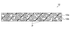
- FIG. 1 is a schematic cross-sectional view conceptually showing an LDH separator used in the present invention.
- FIG. 1 is a schematic cross-sectional view conceptually showing one aspect of plate-like particles bonded perpendicularly or obliquely to the surface of an LDH separator used in the present invention.
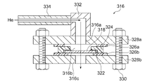
- FIG. FIG. 2 is a conceptual diagram showing an example of a He permeation measurement system used in Example A1; 4B is a schematic cross-sectional view of a sample holder and its peripheral configuration used in the measurement system shown in FIG. 4A;
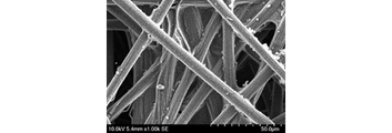
- FIG. 4 is an SEM image of the surface of the LDH separator produced in Example A1.
- Example 2 is an SEM image of the surface of carbon fibers forming carbon paper in the catalyst layer produced in Example B1.
- 6B is an enlarged SEM image of the surface of the carbon fiber shown in FIG. 6A.
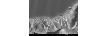
- 6B is an SEM image of a cross section near the surface of the carbon fiber shown in FIG. 6A. 2 is a graph showing charge-discharge characteristics measured for an evaluation cell produced in Example B1.
- FIG. 1 shows one embodiment of an air electrode/separator assembly using a layered double hydroxide (LDH) separator as a hydroxide ion conductive separator.
- LDH layered double hydroxide
- the interface layer 14 is a layer that covers one side of the LDH separator 12 and contains a hydroxide ion conductive material and an electrically conductive material.
- the air electrode layer 16 is a layer in contact with the interface layer 14 and is composed of a porous current collector and a catalyst layer.
- the water-repellent porous layer 19 is a layer that covers the surface of the air electrode layer 16 opposite to the LDH separator 12 .
- a metal-air secondary battery using an LDH separator has the excellent advantage of being able to prevent both the short circuit between the positive and negative electrodes due to metal dendrites and the contamination of carbon dioxide.
- the LDH separator prevents permeation of the electrolytic solution into the air electrode, water does not exist in the air electrode layer, and water must be supplied from the outside during discharge.
- the air electrode/separator assembly advantageously solves this problem.
- the details of the mechanism are not necessarily clear, but it is thought to be as follows. That is, by covering the air electrode layer 16 with the water-repellent porous layer 19, the water generated during charging can be retained in the air electrode layer 16, and as a result, it is not necessary to supply the water necessary for discharging from the outside. Gone. Further, since the water-repellent porous layer 19 is porous, it secures oxygen passages, and the water-repellent porous layer 19 can be introduced without interfering with the charging and discharging reaction.
- the LDH separator 12 is a separator containing a layered double hydroxide (LDH) and/or an LDH-like compound (hereinafter collectively referred to as a hydroxide ion-conducting layered compound). It is defined as selectively passing hydroxide ions using oxide ion conductivity.
- LDH-like compounds are hydroxides and/or oxides of layered crystal structure similar to LDH, although they may not be called LDH, and can be said to be equivalents of LDH.
- LDH layered double hydroxide
- LDH-like compounds are hydroxides and/or oxides of layered crystal structure similar to LDH, although they may not be called LDH, and can be said to be equivalents of LDH.
- LDH can be interpreted as including not only LDH but also LDH-like compounds.
- LDH separators can be known ones as disclosed in Patent Documents 1 to 5, and LDH separators composited with a porous substrate are preferred.
- a particularly preferred LDH separator 12 includes a porous substrate 12a made of a polymeric material and a hydroxide ion-conducting layered compound 12b that closes the pores P of the porous substrate.
- the LDH separator 12 of this aspect will be described later.
- a laminated battery is constructed by alternately incorporating a plurality of air electrode/separator assemblies 10 together with a plurality of metal negative electrodes into a battery container.
- a battery module is constructed by housing a plurality of stacked batteries in one module container. For example, by pressurizing a zinc-air secondary battery, the gap between the negative electrode and the LDH separator 12 that allows zinc dendrite growth is minimized (preferably, the gap is eliminated), thereby making zinc dendrite extension more effective. can be expected to prevent
- the hydroxide ion conductive separator is a separator containing a hydroxide ion conductive material, which selectively allows hydroxide ions to pass through exclusively by utilizing the hydroxide ion conductivity of the hydroxide ion conductive material.
- the hydroxide ion-conducting separator is therefore gas- and/or water-impermeable, in particular gas-impermeable. That is, the hydroxide ion conducting material constitutes all or part of the hydroxide ion conducting separator with such a high degree of density that it exhibits gas impermeability and/or water impermeability. Definitions of gas impermeability and/or water impermeability shall be given below with respect to LDH separator 12 .
- the hydroxide ion-conducting separator may be composited with the porous substrate.
- the interfacial layer 14 includes a hydroxide ion conductive material and an electrically conductive material.
- the hydroxide ion conductive material contained in the interfacial layer 14 has the form of a plurality of plate-like particles 13, and as conceptually shown in FIG. Connected vertically or diagonally.
- the hydroxide ion conductive material contained in the interfacial layer 14 is not particularly limited as long as it has hydroxide ion conductivity and has the form of plate-like particles, but is preferably LDH and/or LDH-like. is a compound. In particular, when observing the microstructure of the surface of the LDH separator 12 produced according to a known technique, as shown in FIG.
- the interfacial resistance is reduced by the presence of such oriented plate-like particles (hydroxide ion conductive material) and the conductive material between the LDH separator 12 and the air electrode layer 16. can be significantly reduced. Therefore, by adopting the same material as the LDH and/or LDH-like compound contained in the LDH separator 12 as the hydroxide ion conductive material contained in the interfacial layer 14, the interfacial layer 14 is formed when the LDH separator 12 is produced. LDH plate-like particles 13 can be prepared at the same time.
- the conductive material contained in the interface layer 14 preferably contains a carbon material.
- the interface layer 14 may be produced by applying a slurry or solution containing a carbon material (for example, carbon ink such as graphene ink) to the surface of the LDH separator 12 to which the plate-like particles 13 are bonded vertically or obliquely.
- a carbon material for example, carbon ink such as graphene ink
- the interface layer 14 may be produced by bringing the catalyst layer and the LDH separator 12 into close contact with each other and making the plate-like particles 13 on the surface of the LDH separator 12 bite into the catalyst layer.
- the interface layer 14 is formed by the portion of the .DELTA.
- the air electrode layer 16 is desirably composed of a porous current collector and a catalyst layer.
- the porous current collector is not particularly limited as long as it is composed of a conductive material having gas diffusion properties, but is composed of at least one selected from the group consisting of carbon, nickel, stainless steel, and titanium. is preferred, and carbon is more preferred.
- Specific examples of porous current collectors include carbon paper, nickel foam, stainless non-woven fabric, and any combination thereof, preferably carbon paper.
- a commercially available porous material can be used as the current collector.
- the thickness of the porous current collector is determined from the viewpoint of securing a wide reaction area, that is, a three-phase interface consisting of an ion-conducting phase (LDH), an electronic-conducting phase (porous current collector), and a gas phase (air). , preferably 0.1 to 1 mm, more preferably 0.1 to 0.5 mm, still more preferably 0.1 to 0.3 mm.
- the porosity of the catalyst layer is preferably 60% or more, more preferably 70% or more, and still more preferably 70 to 95%. Especially in the case of carbon paper, it is more preferably 60 to 90%, still more preferably 70 to 90%, and particularly preferably 75 to 85%.
- the catalyst layer is preferably filled with a mixture comprising a hydroxide ion conducting material, an electrically conducting material, an organic polymer, and a cathode catalyst.
- the hydroxide ion conducting material may be the same material as the cathode catalyst, and examples of such materials include LDHs containing transition metals (such as Ni-Fe-LDH, Co-Fe-LDH, and Ni-Fe-LDH). -V-LDH).
- Mg-Al-LDH is an example of a hydroxide ion conductive material that also serves as an air electrode catalyst.
- the conductive material may be the same material as the air electrode catalyst, and examples of such materials include carbon materials, metal nanoparticles, nitrides such as TiN, and LaSr 3 Fe 3 O 10 .
- the hydroxide ion conductive material contained in the catalyst layer is not particularly limited as long as it is a material having hydroxide ion conductivity, but it is preferably LDH and/or an LDH-like compound.
- the composition of LDH is not particularly limited, but the general formula: M 2+ 1 ⁇ x M 3+ x (OH) 2 A n ⁇ x/n ⁇ mH 2 O (wherein M 2+ is at least one divalent positive M 3+ is at least one trivalent cation, A n- is an n-valent anion, n is an integer of 1 or more, and x is 0.1 to 0.4. , m is any real number).
- M 2+ can be any divalent cation, and preferred examples include Ni 2+ , Mg 2+ , Ca 2+ , Mn 2+ , Fe 2+ , Co 2+ , Cu 2+ and Zn 2+ . . M 3+ can be any trivalent cation, but preferred examples include Fe 3+ , V 3+ , Al 3+ , Co 3+ , Cr 3+ , In 3+ .
- each of M 2+ and M 3+ is a transition metal ion.
- M 2+ is a divalent transition metal ion such as Ni 2+ , Mn 2+ , Fe 2+ , Co 2+ , Cu 2+ , and particularly preferably Ni 2+
- M 3+ is Fe 3+ , V 3+ , Co 3+ , Cr 3+ and the like, and particularly preferably Fe 3+ , V 3+ and/or Co 3+
- part of M 2+ may be substituted with metal ions other than transition metals such as Mg 2+ , Ca 2+ and Zn 2+
- part of M 3+ may be substituted with transition metals such as Al 3+ and In 3+ .
- n- may be substituted with metal ions other than A n- can be any anion, but preferred examples include NO 3- , CO 3 2- , SO 4 2- , OH - , Cl - , I - , Br - , F - and more NO 3- and/or CO 3 2- are preferred. Therefore, in the above general formula, it is preferred that M 2+ contains Ni 2+ , M 3+ contains Fe 3+ and A n- contains NO 3- and/or CO 3 2- .
- n is an integer of 1 or more, preferably 1-3.
- x is 0.1 to 0.4, preferably 0.2 to 0.35.
- m is any real number. More specifically, m is a real number to an integer greater than or equal to 0, typically greater than 0 or greater than or equal to 1.
- the conductive material contained in the catalyst layer is preferably at least one selected from the group consisting of conductive ceramics and carbon materials.
- conductive ceramics include LaNiO 3 , LaSr 3 Fe 3 O 10 , and the like.
- carbon materials include, but are not limited to, carbon black, graphite, carbon nanotubes, graphene, reduced graphene oxide, and any combination thereof, and various other carbon materials can also be used.
- the air electrode catalyst contained in the catalyst layer is preferably at least one selected from the group consisting of LDH and other metal hydroxides, metal oxides, metal nanoparticles, and carbon materials, more preferably It is at least one selected from the group consisting of LDH, metal oxides, metal nanoparticles, and carbon materials.
- the LDH is as described above for the hydroxide ion conductive material, and is particularly preferable in that it can function as both the air electrode catalyst and the hydroxide ion conductive material.
- metal hydroxides include Ni--Fe--OH, Ni--Co--OH and any combination thereof, which may further contain a third metal element.
- metal oxides include Co3O4 , LaNiO3 , LaSr3Fe3O10 , and any combination thereof.
- metal nanoparticles typically metal particles with a particle size of 2 to 30 nm
- carbon materials include, but are not limited to, carbon black, graphite, carbon nanotubes, graphene, reduced graphene oxide, and any combination thereof, as described above, and various other carbon materials are also used. be able to. From the viewpoint of improving the catalytic performance of the carbon material, the carbon material preferably further contains a metal element and/or other elements such as nitrogen, boron, phosphorus, and sulfur.
- a known binder resin can be used as the organic polymer contained in the catalyst layer.
- organic polymers include butyral-based resins, vinyl alcohol-based resins, celluloses, vinyl acetal-based resins, fluorine-based resins, and the like, with butyral-based resins and fluorine-based resins being preferred.
- the catalyst layer may have a portion with low porosity in order to efficiently exchange hydroxide ions with the LDH separator 12 .
- the porosity of the low porosity portion is preferably 30 to 60%, more preferably 35 to 60%, still more preferably 40 to 55%.
- the average pore diameter in the low porosity portion of the catalyst layer is preferably 5 ⁇ m or less, more preferably 0.5 to 4 ⁇ m, still more preferably 1 to 3 ⁇ m.
- the porosity and average pore diameter of the catalyst layer were measured by a) polishing the cross-section of the catalyst layer with a cross-section polisher (CP), and b) using a SEM (scanning electron microscope) to examine the cross-section of the catalyst layer at a magnification of 10,000. Images are acquired in two fields, c) based on the image data of the acquired cross-sectional images, image analysis software (eg, Image-J) is used to binarize the images, and d) the area of each pore in each of the two fields of view. is obtained, the porosity and the pore diameter of each pore are calculated, and the average value thereof is used as the porosity and the average pore diameter of the catalyst layer.
- image analysis software eg, Image-J
- the pore diameter is obtained by converting the length per pixel of the image from the actual size, assuming that each pore is a perfect circle, and dividing the area of each pore obtained from image analysis by the circumference ratio. It can be calculated by multiplying the square root by 2, and the porosity can be calculated by dividing the number of pixels corresponding to pores by the number of pixels in the total area and multiplying by 100.
- the catalyst layer can be produced by preparing a paste containing a hydroxide ion conductive material, a conductive material, an organic polymer, and an air electrode catalyst and applying it to the surface of the LDH separator 12 .
- the paste is prepared by appropriately adding an organic polymer (binder resin) and an organic solvent to a mixture of a hydroxide ion conductive material, a conductive material, and an air electrode catalyst, and using a known kneader such as a three-roll mill. You should go.
- organic solvents include alcohols such as butyl carbitol and terpineol, acetate solvents such as butyl acetate, and N-methyl-2-pyrrolidone.
- the paste can be applied to the LDH separator 12 by printing. This printing can be carried out by various known printing methods, but is preferably carried out by screen printing.
- the air electrode/separator assembly is preferably used in metal-air secondary batteries. That is, according to a preferred embodiment of the present invention, a metal air separator comprising an air electrode/separator assembly, a metal negative electrode, and an electrolytic solution, in which the electrolytic solution is isolated from the air electrode layer 16 via the LDH separator 12.
- a secondary battery is provided.
- a zinc-air secondary battery using a zinc electrode as a metal negative electrode is particularly preferred.
- the metal-air secondary battery preferably has a structure in which the metal negative electrode, the LDH separator 12, the air electrode layer 16, and the water-repellent porous layer 19 are stacked in order from the top. Therefore, the metal-air secondary battery is preferably a stationary metal-air secondary battery.
- a stationary metal-air secondary battery is a stationary metal-air secondary battery that is installed after securing a predetermined space, and is distinguished from a portable metal-air secondary battery.
- the metal negative electrode, the LDH separator 12, the air electrode layer 16, and the water-repellent porous layer 19 are vertically stacked in a "horizontal" state.
- horizontal means that the main surface of the object (that is, the layer surface of each layer and the film surface of the separator) is substantially parallel to the horizontal plane.
- sideways and parallel should not be interpreted strictly, and it is permissible to have an inclination that can be recognized as sideways or approximately parallel (to the horizontal plane) in light of common sense or social conventions. and Therefore, “horizontally” does not necessarily mean that the angle between the horizontal plane and the main surface is 0 degrees, which is completely parallel, and the angle between the horizontal plane and the main surface is less than 30 degrees, less than 20 degrees, less than 10 degrees, or 5 degrees. may be less than
- the water-repellent porous layer 19 according to a preferred embodiment of the present invention will be described below.
- the water-repellent porous layer of this embodiment is required to have a predetermined air permeability, and its porosity is preferably 30% or more, more preferably 30 to 90%, still more preferably 50 to 80%, and particularly preferably 60 to 90%. 70%.
- the measurement of the porosity may be performed in the same manner as the measurement of the porosity of the catalyst layer described above.
- the thickness of the water-repellent porous layer 19 is preferably 0.01-1 mm, more preferably 0.01-0.1 mm.
- Examples of the water-repellent porous material forming the water-repellent porous layer 19 include fluororesins such as fully fluorinated resins, partially fluorinated resins, and polyvinyl fluoride.
- a porous material coated with water-repellent fine particles may be used as the water-repellent porous layer 19 .
- the porous material is not particularly limited as long as it has air permeability, but preferred examples thereof include a resin porous sheet, a metal mesh, and a carbon sheet, and more preferably a resin porous sheet.
- Preferred examples of the water-repellent fine particles include fluororesins.
- the air electrode layer 16 By covering the air electrode layer 16 with the water-repellent porous layer 19 having water repellency and air permeability, O 2 necessary for the charge/discharge reaction can enter and exit the air electrode, and water generated during charging can pass through the air electrode layer. 16. Water remaining in the cathode layer 16 is used for reactions during charging. Since the reaction of water is completed within the air electrode layer 16 in this way, humidification from the outside is unnecessary.
- LDH Separator LDH separator 12 according to a preferred embodiment of the present invention will now be described. Although the following description assumes a zinc-air secondary battery, the LDH separator 12 according to this embodiment can also be applied to other metal-air secondary batteries such as lithium-air secondary batteries. As described above, the LDH separator 12 of this embodiment, as conceptually shown in FIG. . In FIG. 2, the area of the hydroxide ion-conducting layered compound 12b is not connected between the upper surface and the lower surface of the LDH separator 12, but this is because the section is drawn two-dimensionally.
- the area of the hydroxide ion conductive layered compound 12b is connected between the upper surface and the lower surface of the LDH separator 12, thereby increasing the hydroxide ion conductivity of the LDH separator 12.
- the porous substrate 12a is made of a polymer material, and the pores of the porous substrate 12a are closed with the hydroxide ion-conducting layered compound 12b.
- the pores of the porous base material 12a do not have to be completely closed, and residual pores P may slightly exist.
- the LDH separator 12 By closing the pores of the polymeric porous substrate 12a with the hydroxide ion-conducting layered compound 12b and densifying it to a high degree, the LDH separator 12 can more effectively suppress short circuits caused by zinc dendrites. can be provided.
- the LDH separator 12 of this embodiment not only has the desired ion conductivity required for a separator based on the hydroxide ion conductivity possessed by the hydroxide ion conducting layered compound 12b, but also has flexibility. and excellent in strength. This is due to the flexibility and strength of the polymer porous substrate 12a itself contained in the LDH separator 12. That is, since the LDH separator 12 is densified in such a manner that the pores of the porous polymer substrate 12a are sufficiently blocked with the hydroxide ion-conducting layered compound 12b, the porous polymer substrate 12a and the hydroxide The material ion-conducting layered compound 12b is harmoniously integrated as a highly composite material. It can be said that this is offset or reduced by the flexibility and strength of the material 12a.
- the LDH separator 12 of this embodiment is desired to have extremely few residual pores P (pores not blocked by the hydroxide ion conducting layered compound 12b). Due to the residual pores P, the LDH separator 12 has an average porosity of, for example, 0.03% or more and less than 1.0%, preferably 0.05% or more and 0.95% or less, more preferably 0.05% or more and 0.9% or less, more preferably 0.05 to 0.8%, and most preferably 0.05 to 0.5%. When the average porosity is within the above range, the pores of the porous substrate 12a are sufficiently blocked with the hydroxide ion conducting layered compound 12b, resulting in an extremely high degree of denseness, which is attributed to zinc dendrites. A short circuit can be suppressed more effectively.
- the LDH separator 12 can exhibit sufficient functions as a hydroxide ion-conducting separator.
- the average porosity was measured by a) cross-sectional polishing of the LDH separator with a cross-section polisher (CP), and b) a cross-sectional image of the functional layer at a magnification of 50,000 times with an FE-SEM (field emission scanning electron microscope). Two fields of view are acquired, c) based on the image data of the acquired cross-sectional image, the porosity of each of the two fields of view is calculated using image inspection software (e.g., HDDevelop, manufactured by MVTecSoftware), and the average value of the obtained porosities is calculated. It can be done by asking.
- image inspection software e.g., HDDevelop, manufactured by MVTecSoftware
- the LDH separator 12 is a separator containing a hydroxide ion-conducting layered compound 12b, and separates a positive electrode plate and a negative electrode plate so as to allow hydroxide ion conduction when incorporated in a zinc secondary battery. That is, the LDH separator 12 functions as a hydroxide ion conducting separator. Therefore, the LDH separator 12 is gas impermeable and/or water impermeable. Therefore, the LDH separator 12 is preferably densified to be gas impermeable and/or water impermeable.
- having gas impermeability means that helium gas is brought into contact with one side of the measurement object in water at a differential pressure of 0.5 atm, as described in Patent Documents 2 and 3. This means that no bubbles caused by the helium gas are observed from the other side even when the surface is exposed.
- the term “having water impermeability” means that water in contact with one side of the object to be measured does not permeate to the other side, as described in Patent Documents 2 and 3. . That is, the fact that the LDH separator 12 has gas impermeability and/or water impermeability means that the LDH separator 12 has a high degree of denseness to the extent that gas or water does not pass through.
- the LDH separator 12 selectively passes only hydroxide ions due to its hydroxide ion conductivity, and can function as a battery separator. Therefore, the structure is extremely effective in physically preventing penetration of the separator by zinc dendrites generated during charging, thereby preventing short circuits between the positive and negative electrodes. Since the LDH separator 12 has hydroxide ion conductivity, it is possible to efficiently move necessary hydroxide ions between the positive electrode plate and the negative electrode plate, thereby realizing charge-discharge reactions in the positive electrode plate and the negative electrode plate. can be done.
- the LDH separator 12 preferably has a He permeability per unit area of 3.0 cm/min-atm or less, more preferably 2.0 cm/min-atm or less, still more preferably 1.0 cm/min-atm or less. is.
- a separator having a He permeability of 3.0 cm/min ⁇ atm or less can extremely effectively suppress permeation of Zn (typically permeation of zinc ions or zincate ions) in the electrolytic solution. In this way, it is theoretically considered that the separator of this embodiment can effectively suppress the growth of zinc dendrites when used in a zinc secondary battery by significantly suppressing Zn permeation.
- the He permeation rate is determined through a step of supplying He gas to one side of the separator to allow the He gas to permeate the separator, and a step of calculating the He permeation rate and evaluating the compactness of the hydroxide ion conductive separator. measured.
- the degree of He permeation is determined by the formula F/(P ⁇ S) using the permeation amount F of He gas per unit time, the differential pressure P applied to the separator when the He gas permeates, and the membrane area S through which the He gas permeates. calculate.
- He gas has the smallest constitutional unit among a wide variety of atoms and molecules that can constitute gas, and is extremely low in reactivity. That is, He does not form molecules, and constitutes He gas by He atoms alone.
- hydrogen gas is composed of H 2 molecules, a single He atom is smaller as a gas constituent unit.
- H2 gas is dangerous because it is a combustible gas.
- the hydroxide ion conducting layered compound 12b which is LDH and/or an LDH-like compound, closes the pores of the porous substrate 12a.
- LDH is composed of a plurality of hydroxide base layers and intermediate layers interposed between the plurality of hydroxide base layers.
- the hydroxide base layer is mainly composed of metal elements (typically metal ions) and OH groups.
- the intermediate layer of LDH is composed of anions and H2O .
- the anion is a monovalent or higher anion, preferably a monovalent or divalent ion.
- the anions in LDH include OH - and/or CO 3 2- .
- LDH also has excellent ionic conductivity due to its inherent properties.
- LDH is M 2+ 1 ⁇ x M 3+ x (OH) 2 A n ⁇ x/n ⁇ mH 2 O, where M 2+ is a divalent cation and M 3+ is a trivalent is a cation, A n- is an n-valent anion, n is an integer of 1 or more, x is 0.1 to 0.4, and m is 0 or more). known to represent.
- M 2+ can be any divalent cation, but preferred examples include Mg 2+ , Ca 2+ and Zn 2+ , more preferably Mg 2+ .
- M 3+ can be any trivalent cation, but preferred examples include Al 3+ or Cr 3+ , more preferably Al 3+ .
- a n- can be any anion, but preferred examples include OH - and CO 3 2- . Therefore, in the above basic composition formula, it is preferred that M 2+ contains Mg 2+ , M 3+ contains Al 3+ , and A n- contains OH - and/or CO 3 2- .
- n is an integer of 1 or more, preferably 1 or 2.
- x is 0.1 to 0.4, preferably 0.2 to 0.35.
- m is any number denoting the number of moles of water and is a real number equal to or greater than 0, typically greater than 0 or 1 or greater.
- the above basic compositional formula is merely a formula of a "basic composition" which is generally representatively exemplified for LDH, and the constituent ions can be appropriately replaced.
- part or all of M 3+ in the above basic composition formula may be replaced with a cation having a valence of tetravalent or higher. may be changed as appropriate.
- the hydroxide base layer of LDH may contain Ni, Al, Ti and OH groups.
- the intermediate layer is composed of anions and H2O as described above.
- the alternately laminated structure itself of the hydroxide basic layer and the intermediate layer is basically the same as the generally known alternately laminated structure of LDH. , Ti and OH groups, it is possible to exhibit excellent alkali resistance.
- the LDH of this embodiment is because Al, which was conventionally thought to be easily eluted in alkaline solutions, becomes less likely to be eluted in alkaline solutions due to some interaction with Ni and Ti. be done.
- Ni in LDH can take the form of nickel ions.
- Nickel ions in LDH are typically considered to be Ni 2+ , but are not particularly limited as they may have other valences such as Ni 3+ .
- Al in LDH can take the form of aluminum ions.
- Aluminum ions in LDH are typically considered to be Al 3+ , but are not particularly limited as other valences are possible.
- Ti in LDH can take the form of titanium ions. Titanium ions in LDH are typically considered to be Ti 4+ , but are not particularly limited as they may have other valences such as Ti 3+ .
- the hydroxide base layer may contain other elements or ions as long as it contains Ni, Al, Ti and OH groups.
- the hydroxide base layer preferably contains Ni, Al, Ti and OH groups as main constituents. That is, the hydroxide base layer preferably consists mainly of Ni, Al, Ti and OH groups.
- the hydroxide base layer is therefore typically composed of Ni, Al, Ti, OH groups and possibly unavoidable impurities. Unavoidable impurities are arbitrary elements that can be unavoidably mixed in the manufacturing method, and can be mixed in LDH, for example, derived from raw materials and base materials. As mentioned above, since the valences of Ni, Al and Ti are not always certain, it is impractical or impossible to strictly specify LDH by a general formula.
- the hydroxide base layer is composed mainly of Ni 2+ , Al 3+ , Ti 4+ and OH groups
- the corresponding LDH has the general formula: Ni 2+ 1-xy Al 3+ x Ti 4+ y (OH) 2 A n ⁇ (x+2y)/n ⁇ mH 2 O
- a n ⁇ is an n-valent anion
- n is an integer of 1 or more, preferably 1 or 2, and 0 ⁇ x ⁇ 1, preferably 0.01 ⁇ x ⁇ 0.5, 0 ⁇ y ⁇ 1, preferably 0.01 ⁇ y ⁇ 0.5, 0 ⁇ x+y ⁇ 1, m is 0 or more, typically 0 or a real number equal to or greater than 1).
- LDH-like compound is a hydroxide and/or oxide with a layered crystal structure similar to LDH, although it may not be called LDH.
- Preferred LDH-like compounds are described below.
- the LDH separator 12 includes the hydroxide ion-conducting layered compound 12b and the porous substrate 12a (typically composed of the porous substrate 12a and the hydroxide ion-conducting layered compound 12b). 12, the hydroxide ion-conducting layered compound fills the pores of the porous substrate so as to exhibit hydroxide ion conductivity and gas impermeability (and thus function as an LDH separator exhibiting hydroxide ion conductivity). block the It is particularly preferable that the hydroxide ion-conducting layered compound 12b is incorporated throughout the thickness direction of the polymeric porous substrate 12a.
- the thickness of the LDH separator is preferably 3-80 ⁇ m, more preferably 3-60 ⁇ m, still more preferably 3-40 ⁇ m.
- the porous base material 12a is made of a polymeric material.
- the porous polymer substrate 12a has the following characteristics: 1) flexibility (and therefore, it is difficult to break even if it is thin); 4) Easy to manufacture and handle.
- 5) the LDH separator containing a porous substrate made of a polymeric material can be easily folded or sealingly bonded by making use of the advantage derived from the above 1) flexibility.
- Preferred examples of polymeric materials include polystyrene, polyether sulfone, polypropylene, epoxy resin, polyphenylene sulfide, fluororesin (tetrafluorinated resin: PTFE, etc.), cellulose, nylon, polyethylene, and any combination thereof. .
- thermoplastic resins suitable for hot pressing polystyrene, polyether sulfone, polypropylene, epoxy resin, polyphenylene sulfide, fluororesin (tetrafluorinated resin: PTFE, etc.), nylon, polyethylene and any of them and the like.
- All of the various preferred materials described above have alkali resistance as resistance to battery electrolyte.
- Particularly preferred polymer materials are polyolefins such as polypropylene and polyethylene, and most preferably polypropylene or polyethylene, because they are excellent in hot water resistance, acid resistance and alkali resistance and are low in cost.
- the hydroxide ion-conducting layered compound is incorporated throughout the thickness direction of the porous substrate (for example, most or almost all of the inside of the porous substrate).
- the pores are filled with the hydroxide ion-conducting layered compound) is particularly preferred.
- a commercially available microporous polymer membrane can be preferably used as such a porous polymer substrate.
- the LDH separator of this embodiment is produced by (i) preparing a composite material containing a hydroxide ion-conducting layered compound according to a known method (see, for example, Patent Documents 1 to 3) using a polymeric porous substrate, and (ii) It can be produced by pressing this hydroxide ion-conducting layered compound-containing composite material.
- the pressing method may be, for example, roll pressing, uniaxial pressing, CIP (cold isostatic pressing), or the like, and is not particularly limited, but is preferably roll pressing. It is preferable to carry out this pressing while heating since the porous polymeric substrate is softened and the pores of the porous substrate can be sufficiently blocked with the hydroxide ion-conducting layered compound.
- a sufficiently softening temperature for example, in the case of polypropylene and polyethylene, it is preferable to heat at 60 to 200°C.
- the average porosity resulting from residual pores in the LDH separator can be significantly reduced.
- the LDH separator can be densified to an extremely high degree, and therefore short circuits caused by zinc dendrites can be more effectively suppressed.
- the morphology of the residual pores can be controlled, whereby an LDH separator with desired denseness or average porosity can be obtained.
- the method for producing a composite material containing a hydroxide ion-conducting layered compound (i.e., a crude LDH separator) before being pressed is not particularly limited, and a known method for producing an LDH-containing functional layer and a composite material (i.e., an LDH separator) (such as See Patent Documents 1 to 3) can be produced by appropriately changing various conditions.
- a porous substrate is prepared, and (2) a titanium oxide sol or a mixed sol of alumina and titania is applied to the porous substrate and heat-treated to form a titanium oxide layer or an alumina-titania layer, (3) immersing the porous substrate in a raw material aqueous solution containing nickel ions (Ni 2+ ) and urea; (4) hydrothermally treating the porous substrate in the raw material aqueous solution;
- a functional layer containing a hydroxide ion-conducting layered compound and a composite material ie, LDH separator
- a titanium oxide layer or an alumina-titania layer on the porous substrate in the above step (2), not only is the raw material for the hydroxide ion conducting layered compound provided, but also the hydroxide ion conducting layered compound crystal is formed.
- a highly densified hydroxide ion conducting layered compound-containing functional layer can be uniformly formed in the porous substrate.
- the presence of urea in the above step (3) raises the pH value by generating ammonia in the solution using hydrolysis of urea, and coexisting metal ions form hydroxides. can obtain a hydroxide ion-conducting layered compound.
- the hydrolysis is accompanied by the generation of carbon dioxide, a hydroxide ion-conducting layered compound whose anion is a carbonate ion type can be obtained.
- the alumina in (2) above and titania mixed sol to the substrate is preferably carried out in such a manner that the mixed sol penetrates all or most of the inside of the substrate.
- preferable application methods include dip coating, filtration coating, and the like, and dip coating is particularly preferable.
- the adhesion amount of the mixed sol can be adjusted by adjusting the number of coatings such as dip coating.
- the substrate coated with the mixed sol by dip coating or the like may be dried and then subjected to the steps (3) and (4).
- the LDH separator may contain an LDH-like compound.
- LDH-like compounds are (a) is a hydroxide and/or oxide having a layered crystal structure containing Mg and one or more elements containing at least Ti selected from the group consisting of Ti, Y and Al, or (b) (i ) Ti, Y, and optionally Al and/or Mg, and (ii) an additional element M that is at least one selected from the group consisting of In, Bi, Ca, Sr, and Ba.
- (c) is a hydroxide and/or oxide, or (c) is a hydroxide and/or oxide of layered crystal structure comprising Mg, Ti, Y, and optionally Al and/or In, said (c) in the LDH-like compound is present in the form of a mixture with In(OH) 3 .
- the LDH-like compound is a hydroxide having a layered crystal structure containing Mg and at least one element containing at least Ti selected from the group consisting of Ti, Y and Al. and/or an oxide.
- Typical LDH-like compounds are therefore complex hydroxides and/or complex oxides of Mg, Ti, optionally Y and optionally Al.
- the LDH-like compound preferably does not contain Ni.
- the LDH-like compound may further contain Zn and/or K. By doing so, the ionic conductivity of the LDH separator can be further improved.
- LDH-like compounds can be identified by X-ray diffraction. Specifically, when X-ray diffraction is performed on the surface of the LDH separator, the A peak derived from an LDH-like compound is detected in the range.
- LDH is a material with an alternating layer structure in which exchangeable anions and H 2 O are present as intermediate layers between stacked hydroxide elementary layers.
- a peak due to the crystal structure of LDH that is, the (003) peak of LDH
- a peak due to the crystal structure of LDH that is, the (003) peak of LDH
- the interlayer distance of the layered crystal structure can be determined by Bragg's equation using 2 ⁇ corresponding to the peak derived from the LDH-like compound in X-ray diffraction.
- the interlayer distance of the layered crystal structure constituting the LDH-like compound thus determined is typically 0.883 to 1.8 nm, more typically 0.883 to 1.3 nm.
- the atomic ratio of Mg/(Mg+Ti+Y+Al) in the LDH-like compound determined by energy dispersive X-ray spectroscopy (EDS) is preferably 0.03 to 0.25, It is more preferably 0.05 to 0.2.
- the atomic ratio of Ti/(Mg+Ti+Y+Al) in the LDH-like compound is preferably 0.40 to 0.97, more preferably 0.47 to 0.94.
- the atomic ratio of Y/(Mg+Ti+Y+Al) in the LDH-like compound is preferably 0 to 0.45, more preferably 0 to 0.37.
- the atomic ratio of Al/(Mg+Ti+Y+Al) in the LDH-like compound is preferably 0 to 0.05, more preferably 0 to 0.03. Within the above range, the alkali resistance is even more excellent, and the effect of suppressing short circuits caused by zinc dendrites (that is, dendrite resistance) can be more effectively realized.
- LDH separators have the general formula: M 2+ 1 ⁇ x M 3+ x (OH) 2 A n ⁇ x/n ⁇ mH 2 O (wherein M 2+ is a divalent cation, M 3+ is a trivalent cation, A n- is an n-valent anion, n is an integer of 1 or more, x is 0.1 to 0.4, and m is 0 or more.
- M 2+ is a divalent cation
- M 3+ is a trivalent cation
- a n- is an n-valent anion
- n is an integer of 1 or more
- x is 0.1 to 0.4
- m is 0 or more.
- the atomic ratios in LDH-like compounds generally deviate from the general formula for LDH. Therefore, it can be said that the LDH-like compound in this aspect generally has a composition ratio (atomic ratio) different from conventional LDH.
- an EDS analyzer eg, X-act, manufactured by Oxford Instruments
- X-act e.g., X-act, manufactured by Oxford Instruments
- the LDH-like compound has a layered crystal structure comprising (i) Ti, Y and optionally Al and/or Mg and (ii) an additional element M It can be hydroxide and/or oxide. Accordingly, typical LDH-like compounds are complex hydroxides and/or complex oxides of Ti, Y, additional element M, optionally Al and optionally Mg.
- the additive element M is In, Bi, Ca, Sr, Ba, or a combination thereof.
- the atomic ratio of Ti/(Mg+Al+Ti+Y+M) in the LDH-like compound determined by energy dispersive X-ray spectroscopy (EDS) is preferably 0.50 to 0.85, It is more preferably 0.56 to 0.81.
- the atomic ratio of Y/(Mg+Al+Ti+Y+M) in the LDH-like compound is preferably 0.03-0.20, more preferably 0.07-0.15.
- the atomic ratio of M/(Mg+Al+Ti+Y+M) in the LDH-like compound is preferably 0.03-0.35, more preferably 0.03-0.32.
- the atomic ratio of Mg/(Mg+Al+Ti+Y+M) in the LDH-like compound is preferably 0 to 0.10, more preferably 0 to 0.02.
- the atomic ratio of Al/(Mg+Al+Ti+Y+M) in the LDH-like compound is preferably 0 to 0.05, more preferably 0 to 0.04.
- LDH separators have the general formula: M 2+ 1 ⁇ x M 3+ x (OH) 2 A n ⁇ x/n ⁇ mH 2 O (wherein M 2+ is a divalent cation, M 3+ is a trivalent cation, A n- is an n-valent anion, n is an integer of 1 or more, x is 0.1 to 0.4, and m is 0 or more.
- M 2+ is a divalent cation
- M 3+ is a trivalent cation
- a n- is an n-valent anion
- n is an integer of 1 or more
- x is 0.1 to 0.4
- m is 0 or more.
- the atomic ratios in LDH-like compounds generally deviate from the general formula for LDH. Therefore, it can be said that the LDH-like compound in this aspect generally has a composition ratio (atomic ratio) different from conventional LDH.
- an EDS analyzer eg, X-act, manufactured by Oxford Instruments
- X-act e.g., X-act, manufactured by Oxford Instruments
- the LDH-like compound is a hydroxide and/or oxide of layered crystal structure comprising Mg, Ti, Y and optionally Al and/or In.
- the LDH-like compound may be present in the form of a mixture with In(OH) 3 .
- the LDH-like compounds of this embodiment are hydroxides and/or oxides of layered crystal structure containing Mg, Ti, Y, and optionally Al and/or In.
- Typical LDH-like compounds are therefore complex hydroxides and/or complex oxides of Mg, Ti, Y, optionally Al and optionally In.
- the LDH-like compound In that can be contained in the LDH-like compound is not only intentionally added to the LDH-like compound, but also inevitably mixed into the LDH-like compound due to the formation of In(OH) 3 or the like. can be anything. Although the above elements may be replaced with other elements or ions to the extent that the basic properties of the LDH-like compound are not impaired, the LDH-like compound preferably does not contain Ni.
- LDH separators have the general formula: M 2+ 1 ⁇ x M 3+ x (OH) 2 A n ⁇ x/n ⁇ mH 2 O (wherein M 2+ is a divalent cation, M 3+ is a trivalent cation, A n- is an n-valent anion, n is an integer of 1 or more, x is 0.1 to 0.4, and m is 0 or more.
- M 2+ is a divalent cation
- M 3+ is a trivalent cation
- a n- is an n-valent anion
- n is an integer of 1 or more
- x is 0.1 to 0.4
- m is 0 or more.
- the atomic ratios in LDH-like compounds generally deviate from the above general formula for LDH. Therefore, it can be said that the LDH-like compound in this aspect generally has a composition ratio (atomic ratio) different from conventional LDH.
- the mixture according to embodiment (c) above contains not only LDH-like compounds but also In(OH) 3 (typically composed of LDH-like compounds and In(OH) 3 ).
- the inclusion of In(OH) 3 can effectively improve the alkali resistance and dendrite resistance of the LDH separator.
- the content of In(OH) 3 in the mixture is not particularly limited, and is preferably an amount that can improve the alkali resistance and dendrite resistance without substantially impairing the hydroxide ion conductivity of the LDH separator.
- In(OH) 3 may have a cubic crystal structure, or may have a structure in which In(OH) 3 crystals are surrounded by an LDH-like compound.
- In(OH) 3 can be identified by X-ray diffraction.
- Example A1 An LDH separator was produced by the following procedure and evaluated.
- Porous Polymer Substrate A commercially available polyethylene microporous membrane having a porosity of 50%, an average pore diameter of 0.1 ⁇ m and a thickness of 20 ⁇ m was prepared as a porous polymer substrate, and 2.0 cm ⁇ 2. It was cut to a size of 0 cm.
- the mixed sol was applied to the substrate prepared in (1) above by dip coating. Dip coating was carried out by immersing the substrate in 100 ml of the mixed sol, lifting it vertically, and drying it in a drier at 90° C. for 5 minutes.
- Nickel nitrate hexahydrate Ni(NO 3 ) 2.6H 2 O, manufactured by Kanto Kagaku Co., Ltd.
- urea ((NH 2 ) 2 CO, manufactured by Sigma - Aldrich)
- Nickel nitrate hexahydrate was weighed to 0.015 mol/L and put into a beaker, and ion-exchanged water was added to bring the total amount to 75 ml.
- Urea weighed at a ratio of urea/NO 3 ⁇ (molar ratio) 16 was added to the mixture, and further stirred to obtain an aqueous raw material solution.
- Evaluation 1 Identification of LDH separator Using an X-ray diffractometer (RINT TTR III, manufactured by Rigaku Corporation), the crystal phase of the LDH separator was determined under the measurement conditions of voltage: 50 kV, current value: 300 mA, measurement range: 10 to 70 °. Measurements were taken to obtain the XRD profile. For the obtained XRD profile, JCPDS card No. Identification was carried out using the diffraction peak of LDH (hydrotalcite compound) described in 35-0964. The LDH separator of this example was identified to be LDH (hydrotalcite compound).
- Evaluation 2 Measurement of thickness The thickness of the LDH separator was measured using a micrometer. The thickness was measured at three points, and the average value thereof was adopted as the thickness of the LDH separator. As a result, the thickness of the LDH separator of this example was 13 ⁇ m.
- Evaluation 3 Measurement of average porosity A cross-section of the LDH separator was polished with a cross-section polisher (CP), and a cross-section image of the LDH separator was obtained in two fields at a magnification of 50,000 with an FE-SEM (ULTRA55, manufactured by Carl Zeiss). did. Based on this image data, image inspection software (HDDevelop, manufactured by MVTecSoftware) was used to calculate the porosity of each of the two fields of view, and the average value thereof was taken as the average porosity of the LDH separator. As a result, the average porosity of the LDH separator of this example was 0.8%.
- He permeation measurement A He permeation test was performed as follows in order to evaluate the denseness of the LDH separator from the viewpoint of He permeation.
- a He permeation measurement system 310 shown in FIGS. 4A and 4B was constructed.
- He gas from a gas cylinder filled with He gas is supplied to a sample holder 316 via a pressure gauge 312 and a flow meter 314 (digital flow meter). It is constructed such that it is permeated from one surface of the separator 318 to the other surface and discharged.
- the sample holder 316 has a structure including a gas supply port 316a, a closed space 316b and a gas discharge port 316c, and was assembled as follows. First, an adhesive 322 was applied along the outer circumference of the LDH separator 318, and attached to a jig 324 (made of ABS resin) having an opening in the center. Butyl rubber packings are provided as sealing members 326a and 326b at the upper and lower ends of the jig 324, and support members 328a and 328b (made of PTFE) having openings formed of flanges are applied from the outside of the sealing members 326a and 326b. ).
- the closed space 316b is defined by the LDH separator 318, the jig 324, the sealing member 326a and the support member 328a.
- the support members 328a and 328b were tightly fastened together by fastening means 330 using screws so that He gas would not leak from portions other than the gas discharge port 316c.
- a gas supply pipe 334 was connected via a joint 332 to the gas supply port 316 a of the sample holder 316 thus assembled.
- He gas was supplied to the He permeation measurement system 310 through the gas supply pipe 334 and allowed to permeate the LDH separator 318 held in the sample holder 316 .
- the gas supply pressure and flow rate were monitored by the pressure gauge 312 and flow meter 314 .
- the He permeability was calculated.
- the He permeation rate is calculated based on the permeation amount F (cm 3 /min) of He gas per unit time, the differential pressure P (atm) applied to the LDH separator during He gas permeation, and the membrane area S (cm 2 ), it was calculated by the formula of F/(P ⁇ S).
- the permeation amount F (cm 3 /min) of He gas was directly read from the flow meter 314 .
- a gauge pressure read from the pressure gauge 312 was used as the differential pressure P.
- the He gas was supplied so that the differential pressure P was within the range of 0.05 to 0.90 atm.
- the He permeability per unit area of the LDH separator was 0.0 cm/min ⁇ atm.
- Example B1-B3 An air electrode/separator assembly comprising two layers, an interface layer and a catalyst layer, on the LDH separator produced in Example A1 was produced by the following procedure and evaluated.
- Nickel nitrate hexahydrate Ni(NO 3 ) 2 6H 2 O, manufactured by Kanto Chemical Co., Inc.
- urea ((NH 2 ) 2 CO, manufactured by Mitsui Chemicals, Inc.)
- Nickel nitrate hexahydrate was weighed so as to be 0.03 mol/L and put into a beaker, and deionized water was added to make the total amount 75 ml.
- urea was added to the solution so that the urea concentration was 0.96 mol/l, and the mixture was further stirred to obtain an aqueous raw material solution.
- FIGS. 6A-6C are obtained.
- FIG. 6B is an enlarged image of the surface of the carbon fibers forming the carbon paper shown in FIG. 6A
- FIG. 6C is an enlarged cross-sectional image near the surface of the carbon fibers shown in FIG. 6A. From these figures, it was observed that a large number of LDH plate-like particles were vertically or obliquely bonded to the surface of the carbon fibers constituting the carbon paper, and that these LDH plate-like particles were connected to each other.
- Example B3 an interface layer (thickness: 0.2 ⁇ m) containing LDH plate-like particles (originating from the LDH separator) and carbon (originating from the carbon slurry) was simultaneously formed between the LDH separator and the air electrode layer.
- a PTFE porous film manufactured by Chukoh Kasei Co., Ltd., SEF-010 was adhered onto the catalyst layer (air electrode layer) to form a water-repellent porous layer (porosity: 65%).
- SEF-010 a PTFE porous film
- a metal zinc plate was laminated as a negative electrode on the air electrode/separator assembly and the LDH separator side so that the negative electrode faces upward.
- the obtained laminate was sandwiched with a pressing jig in a state in which the sealing member was engaged with the outer peripheral portion of the LDH separator so as to be able to adhere thereto, and was firmly fixed with a screw.
- This holding jig has an oxygen introduction port on the air electrode side and a liquid injection port through which an electrolytic solution can be introduced on the metal zinc plate side.
- a 5.4 M KOH aqueous solution saturated with zinc oxide was added to the negative electrode side of the assembly thus obtained to prepare an evaluation cell.
- Example B2 comparative example
- Example B3 comparative example
- Example B3 comparative example
Abstract
Description
正極: O2+2H2O+4e-→4OH-
負極: 2Zn+4OH-→2ZnO+2H2O+4e- One of the innovative battery candidates is the metal-air secondary battery. In a metal-air secondary battery, oxygen, which is the positive electrode active material, is supplied from the air, so the space inside the battery container can be used to the maximum for filling the negative electrode active material, which in principle results in a high energy density. can be realized. For example, in a zinc-air secondary battery using zinc as a negative electrode active material, an alkaline aqueous solution such as potassium hydroxide is used as the electrolyte, and a separator (partition wall) is used to prevent short-circuiting between the positive and negative electrodes. During discharge, as shown in the following reaction formula, O 2 is reduced on the air electrode (positive electrode) side to generate OH − , while zinc is oxidized on the negative electrode side to generate ZnO.
Positive electrode: O 2 +2H 2 O+4e − →4OH −
Negative electrode: 2Zn+4OH − →2ZnO+2H 2 O+4e −
[項1]
水酸化物イオン伝導セパレータと、
前記水酸化物イオン伝導セパレータの一面側を覆う、水酸化物イオン伝導材料及び導電性材料を含む界面層と、
前記界面層上に設けられ、多孔性集電体及びその表面を覆う層状複水酸化物(LDH)で構成される触媒層を含む空気極層と、
前記空気極の、前記水酸化物イオン伝導セパレータと反対側の面を覆う、撥水多孔層と、
を備えた、空気極/セパレータ接合体。
[項2]
前記撥水多孔層を構成する撥水多孔材が、フッ素樹脂材料を含む、項1に記載の空気極/セパレータ接合体。
[項3]
前記フッ素樹脂材料が、完全フッ素化樹脂、部分フッ素化樹脂、ポリフッ化ビニル、及びフッ素化樹脂共重合体からなる群から選択される少なくとも1種である、項2に記載の空気極/セパレータ接合体。
[項4]
前記撥水多孔層が、撥水性微粒子で被覆された多孔材で構成される、項1に記載の空気極/セパレータ接合体。
[項5]
前記撥水性微粒子が、フッ素樹脂材料を含む、項4に記載の空気極/セパレータ接合体。
[項6]
前記多孔材が、高分子材料、金属メッシュ、及びカーボンシートからなる群から選択される少なくとも1種である、項4又は5に記載の空気極/セパレータ接合体。
[項7]
前記撥水多孔層が、0.01~1mmの厚さを有する、項4~6のいずれか一項に記載の空気極/セパレータ接合体。
[項8]
前記撥水多孔層が、30%以上の気孔率を有する、項4~7のいずれか一項に記載の空気極/セパレータ接合体。
[項9]
前記界面層に含まれる前記水酸化物イオン伝導材料が、前記水酸化物イオン伝導セパレータに含まれる水酸化物イオン伝導材料と同種の材料である、項1~8のいずれか一項に記載の空気極/セパレータ接合体。
[項10]
前記界面層に含まれる前記水酸化物イオン伝導材料、及び前記水酸化物イオン伝導セパレータに含まれる水酸化物イオン伝導材料がいずれもLDH及び/又はLDH様化合物である、項9に記載の空気極/セパレータ接合体。
[項11]
前記界面層に含まれる前記導電性材料が、炭素材料を含む、項1~10のいずれか一項に記載の空気極/セパレータ接合体。
[項12]
前記炭素材料が、カーボンブラック、グラファイト、カーボンナノチューブ、グラフェン、及び還元酸化グラフェンからなる群から選択される少なくとも1種である、項11に記載の空気極/セパレータ接合体。
[項13]
前記触媒層が、60%以上の気孔率を有する、項1~12のいずれか一項に記載の空気極/セパレータ接合体。
[項14]
前記触媒層に含まれるLDHが複数のLDH板状粒子の形態を有し、該複数のLDH板状粒子が前記多孔性集電体の表面に対して垂直又は斜めに結合している、項1~13のいずれか一項に記載の空気極/セパレータ接合体。
[項15]
前記触媒層において前記複数のLDH板状粒子が互いに連結している、項14に記載の空気極/セパレータ接合体。
[項16]
前記多孔性集電体が、カーボン、ニッケル、ステンレス、及びチタンからなる群から選択される少なくとも1種で構成される、項1~15のいずれか一項に記載の空気極/セパレータ接合体。
[項17]
前記多孔性集電体が、0.1~1mmの厚さを有する、項1~16のいずれか一項に記載の空気極/セパレータ接合体。
[項18]
前記触媒層が、水酸化物イオン伝導材料、導電性材料、有機高分子、及び空気極触媒を含む混合物(ただし、水酸化物イオン伝導材料は空気極触媒と同一材料でありうる、また、導電性材料は空気極触媒と同一材料でありうる)を含む、項1~17のいずれか一項に記載の空気極/セパレータ接合体。
[項19]
前記水酸化物イオン伝導セパレータが、層状複水酸化物(LDH)セパレータである、項1~18のいずれか一項に記載の空気極/セパレータ接合体。
[項20]
前記LDHセパレータが多孔質基材と複合化されている、項19に記載の空気極/セパレータ接合体。
[項21]
項1~20のいずれか一項に記載の空気極/セパレータ接合体と、金属負極と、電解液とを備え、前記電解液が前記水酸化物イオン伝導セパレータを介して前記空気極層と隔離されており、
上から順に、前記金属負極、前記水酸化物イオン伝導セパレータ、前記空気極層、及び前記撥水多孔層が位置するように積層された、金属空気二次電池。 According to the present invention, the following aspects are provided.
[Section 1]
a hydroxide ion conducting separator;
an interfacial layer comprising a hydroxide ion conducting material and a conductive material covering one side of the hydroxide ion conducting separator;
an air electrode layer provided on the interfacial layer and including a catalyst layer composed of a porous current collector and a layered double hydroxide (LDH) covering the surface thereof;
a water-repellent porous layer covering the surface of the air electrode opposite to the hydroxide ion conducting separator;
An air electrode/separator assembly.
[Section 2]
[Section 3]
[Section 4]
[Section 5]
[Section 6]
[Section 7]
[Item 8]
[Item 9]
[Item 10]
[Item 11]
Item 11. The air electrode/separator assembly according to any one of
[Item 12]
[Item 13]
[Item 14]
[Item 15]
Item 15. The air electrode/separator assembly according to
[Item 16]
[Item 17]
Item 17. The air electrode/separator assembly according to any one of
[Item 18]
The catalyst layer is a mixture containing a hydroxide ion conductive material, a conductive material, an organic polymer, and an air electrode catalyst (however, the hydroxide ion conductive material can be the same material as the air electrode catalyst, and the conductive 18. The air electrode/separator assembly according to any one of
[Item 19]
19. The air electrode/separator assembly according to any one of
[Section 20]
Item 20. The air electrode/separator assembly according to
[Section 21]
21. An air electrode/separator assembly according to any one of
A metal-air secondary battery in which the metal negative electrode, the hydroxide ion conductive separator, the air electrode layer, and the water-repellent porous layer are stacked in this order from the top.
図1に、水酸化物イオン伝導セパレータとして層状複水酸化物(LDH)セパレータを用いた空気極/セパレータ接合体の一態様を示す。なお、以下の説明においてLDHセパレータに関して言及される内容は、技術的な整合性を損なわないかぎりにおいて、LDHセパレータ以外の水酸化物イオン伝導セパレータにも同様に当てはまるものとする。すなわち、以下の記載において、技術的な整合性を損なわないかぎりにおいて、LDHセパレータは水酸化物イオン伝導セパレータと読み替え可能である。 Air electrode/separator assembly FIG. 1 shows one embodiment of an air electrode/separator assembly using a layered double hydroxide (LDH) separator as a hydroxide ion conductive separator. It should be noted that the content referred to in the following description regarding LDH separators is similarly applicable to hydroxide ion conductive separators other than LDH separators, as long as technical consistency is not impaired. That is, in the following description, the LDH separator can be read as the hydroxide ion conductive separator as long as it does not impair technical consistency.
本発明の好ましい態様による撥水多孔層19について以下に説明する。本態様の撥水多孔層は所定の通気性を有することが求められ、その気孔率は30%以上が好ましく、より好ましくは30~90%、さらに好ましくは50~80%、特に好ましくは60~70%である。気孔率の測定は前述した触媒層の気孔率の測定と同様にして行えばよい。撥水多孔層19の厚みは好ましくは0.01~1mm、さらに好ましくは0.01~0.1mmである。撥水多孔層19を構成する撥水多孔材の例としては、完全フッ素化樹脂、部分フッ素化樹脂、ポリフッ化ビニルといったフッ素樹脂が挙げられる。 Water- Repellent Porous Layer The water-repellent
本発明の好ましい態様によるLDHセパレータ12について以下に説明する。なお、以下の説明は亜鉛空気二次電池を想定した記載となっているが、本態様によるLDHセパレータ12はリチウム空気二次電池等の他の金属空気二次電池にも適用可能である。前述したとおり、本態様のLDHセパレータ12は、図2に概念的に示されるように、多孔質基材12aと、LDH及び/又はLDH様化合物である水酸化物イオン伝導層状化合物12bとを含む。なお、図2においてLDHセパレータ12の上面と下面の間で水酸化物イオン伝導層状化合物12bの領域が繋がっていないように描かれているが、これは断面として二次元的に描かれているためであり、奥行きを考慮した三次元的にはLDHセパレータ12の上面と下面の間で水酸化物イオン伝導層状化合物12bの領域が繋がっており、それによりLDHセパレータ12の水酸化物イオン伝導性が確保されている。多孔質基材12aは高分子材料製であり、多孔質基材12aの孔を水酸化物イオン伝導層状化合物12bが塞いでいる。もっとも、多孔質基材12aの孔は完全に塞がれている必要はなく、残留気孔Pが僅かに存在しうる。このように高分子多孔質基材12aの孔を水酸化物イオン伝導層状化合物12bで塞いで高度に緻密化することで、亜鉛デンドライトに起因する短絡をより一層効果的に抑制可能なLDHセパレータ12を提供することができる。 LDH
本発明の好ましい態様によれば、LDHセパレータは、LDH様化合物を含むものであることができる。LDH様化合物の定義は前述したとおりである。好ましいLDH様化合物は、
(a)Mgと、Ti、Y及びAlからなる群から選択される少なくともTiを含む1以上の元素とを含む層状結晶構造の水酸化物及び/又は酸化物である、又は
(b)(i)Ti、Y、及び所望によりAl及び/又はMgと、(ii)In、Bi、Ca、Sr及びBaからなる群から選択される少なくとも1種である添加元素Mとを含む、層状結晶構造の水酸化物及び/又は酸化物である、又は
(c)Mg、Ti、Y、及び所望によりAl及び/又はInを含む層状結晶構造の水酸化物及び/又は酸化物であり、該(c)において前記LDH様化合物がIn(OH)3との混合物の形態で存在する。 LDH-Like Compound According to a preferred embodiment of the present invention, the LDH separator may contain an LDH-like compound. The definition of LDH-like compounds is as described above. Preferred LDH-like compounds are
(a) is a hydroxide and/or oxide having a layered crystal structure containing Mg and one or more elements containing at least Ti selected from the group consisting of Ti, Y and Al, or (b) (i ) Ti, Y, and optionally Al and/or Mg, and (ii) an additional element M that is at least one selected from the group consisting of In, Bi, Ca, Sr, and Ba. is a hydroxide and/or oxide, or (c) is a hydroxide and/or oxide of layered crystal structure comprising Mg, Ti, Y, and optionally Al and/or In, said (c) in the LDH-like compound is present in the form of a mixture with In(OH) 3 .
LDHセパレータを以下の手順で作製し、その評価を行った。 Example A1
An LDH separator was produced by the following procedure and evaluated.
気孔率50%、平均気孔径0.1μm及び厚さ20μmの市販のポリエチレン微多孔膜を高分子多孔質基材として用意し、2.0cm×2.0cmの大きさになるように切り出した。 (1) Preparation of Porous Polymer Substrate A commercially available polyethylene microporous membrane having a porosity of 50%, an average pore diameter of 0.1 μm and a thickness of 20 μm was prepared as a porous polymer substrate, and 2.0 cm×2. It was cut to a size of 0 cm.
無定形アルミナ溶液(Al-ML15、多木化学株式会社製)と酸化チタンゾル溶液(M6、多木化学株式会社製)をTi/Al(モル比)=2となるように混合して混合ゾルを作製した。混合ゾルを、上記(1)で用意された基材へディップコートにより塗布した。ディップコートは、混合ゾル100mlに基材を浸漬させてから垂直に引き上げ、90℃の乾燥機中で5分間乾燥させることにより行った。 (2) Alumina/titania sol coating on porous polymer substrate Amorphous alumina solution (Al-ML15, manufactured by Taki Chemical Co., Ltd.) and titanium oxide sol solution (M6, manufactured by Taki Chemical Co., Ltd.) were mixed with Ti/Al ( A mixed sol was prepared by mixing so that the molar ratio)=2. The mixed sol was applied to the substrate prepared in (1) above by dip coating. Dip coating was carried out by immersing the substrate in 100 ml of the mixed sol, lifting it vertically, and drying it in a drier at 90° C. for 5 minutes.
原料として、硝酸ニッケル六水和物(Ni(NO3)2・6H2O、関東化学株式会社製、及び尿素((NH2)2CO、シグマアルドリッチ製)を用意した。0.015mol/Lとなるように、硝酸ニッケル六水和物を秤量してビーカーに入れ、そこにイオン交換水を加えて全量を75mlとした。得られた溶液を攪拌した後、溶液中に尿素/NO3 -(モル比)=16の割合で秤量した尿素を加え、更に攪拌して原料水溶液を得た。 (3) Preparation of Raw Material Aqueous Solution As raw materials, nickel nitrate hexahydrate (Ni(NO 3 ) 2.6H 2 O, manufactured by Kanto Kagaku Co., Ltd., and urea ((NH 2 ) 2 CO, manufactured by Sigma - Aldrich) are prepared. Nickel nitrate hexahydrate was weighed to 0.015 mol/L and put into a beaker, and ion-exchanged water was added to bring the total amount to 75 ml. Urea weighed at a ratio of urea/NO 3 − (molar ratio)=16 was added to the mixture, and further stirred to obtain an aqueous raw material solution.
テフロン(登録商標)製密閉容器(オートクレーブ容器、内容量100ml、外側がステンレス製ジャケット)に原料水溶液とディップコートされた基材を共に封入した。このとき、基材はテフロン(登録商標)製密閉容器の底から浮かせて固定し、基材両面に溶液が接するように水平に設置した。その後、水熱温度120℃で24時間水熱処理を施すことにより基材表面と内部にLDHの形成を行った。所定時間の経過後、基材を密閉容器から取り出し、イオン交換水で洗浄し、70℃で10時間乾燥させて、多孔質基材の孔内にLDHを形成させた。こうして、LDHを含む複合材料を得た。 (4) Film formation by hydrothermal treatment The raw material aqueous solution and the dip-coated base material were sealed together in a Teflon (registered trademark) closed container (autoclave container, internal capacity: 100 ml, outer jacket made of stainless steel). At this time, the substrate was lifted from the bottom of the Teflon (registered trademark) closed container and fixed, and placed horizontally so that both surfaces of the substrate were in contact with the solution. Thereafter, a hydrothermal treatment was performed at a hydrothermal temperature of 120° C. for 24 hours to form LDH on the substrate surface and inside. After a predetermined period of time, the substrate was taken out from the sealed container, washed with deionized water, and dried at 70° C. for 10 hours to form LDH in the pores of the porous substrate. Thus, a composite material containing LDH was obtained.
上記LDHを含む複合材料を、1対のPETフィルム(東レ株式会社製、ルミラー(登録商標)、厚さ40μm)で挟み、ロール回転速度3mm/s、ロール温度120℃、ロールギャップ60μmにてロールプレスを行い、LDHセパレータを得た。 (5) Densification by roll press The above composite material containing LDH is sandwiched between a pair of PET films (manufactured by Toray Industries, Inc., Lumirror (registered trademark), thickness 40 μm),
得られたLDHセパレータに対して以下の評価を行った。 (6) Evaluation Results The following evaluations were performed on the obtained LDH separators.
X線回折装置(リガク社製、RINT TTR III)にて、電圧:50kV、電流値:300mA、測定範囲:10~70°の測定条件で、LDHセパレータの結晶相を測定してXRDプロファイルを得た。得られたXRDプロファイルについて、JCPDSカードNO.35-0964に記載されるLDH(ハイドロタルサイト類化合物)の回折ピークを用いて同定を行った。本例のLDHセパレータは、LDH(ハイドロタルサイト類化合物)であることが同定された。 Evaluation 1 : Identification of LDH separator Using an X-ray diffractometer (RINT TTR III, manufactured by Rigaku Corporation), the crystal phase of the LDH separator was determined under the measurement conditions of voltage: 50 kV, current value: 300 mA, measurement range: 10 to 70 °. Measurements were taken to obtain the XRD profile. For the obtained XRD profile, JCPDS card No. Identification was carried out using the diffraction peak of LDH (hydrotalcite compound) described in 35-0964. The LDH separator of this example was identified to be LDH (hydrotalcite compound).
マイクロメータを用いてLDHセパレータの厚さを測定した。3箇所で厚さを測定し、それらの平均値をLDHセパレータの厚さとして採用した。その結果、本例のLDHセパレータの厚さは13μmであった。 Evaluation 2 : Measurement of thickness The thickness of the LDH separator was measured using a micrometer. The thickness was measured at three points, and the average value thereof was adopted as the thickness of the LDH separator. As a result, the thickness of the LDH separator of this example was 13 μm.
クロスセクションポリッシャ(CP)により、LDHセパレータを断面研磨し、FE-SEM(ULTRA55、カールツァイス製)により、50,000倍の倍率でLDHセパレータの断面イメージを2視野取得した。この画像データをもとに、画像検査ソフト(HDevelop、MVTecSoftware製)を用いて、2視野それぞれの気孔率を算出し、それらの平均値をLDHセパレータの平均気孔率とした。その結果、本例のLDHセパレータの平均気孔率は0.8%であった。 Evaluation 3 : Measurement of average porosity A cross-section of the LDH separator was polished with a cross-section polisher (CP), and a cross-section image of the LDH separator was obtained in two fields at a magnification of 50,000 with an FE-SEM (ULTRA55, manufactured by Carl Zeiss). did. Based on this image data, image inspection software (HDDevelop, manufactured by MVTecSoftware) was used to calculate the porosity of each of the two fields of view, and the average value thereof was taken as the average porosity of the LDH separator. As a result, the average porosity of the LDH separator of this example was 0.8%.
He透過性の観点からLDHセパレータの緻密性を評価すべく、He透過試験を以下のとおり行った。まず、図4A及び図4Bに示されるHe透過度測定系310を構築した。He透過度測定系310は、Heガスを充填したガスボンベからのHeガスが圧力計312及び流量計314(デジタルフローメーター)を介して試料ホルダ316に供給され、この試料ホルダ316に保持されたLDHセパレータ318の一方の面から他方の面に透過させて排出させるように構成した。 Evaluation 4 : He permeation measurement A He permeation test was performed as follows in order to evaluate the denseness of the LDH separator from the viewpoint of He permeation. First, a He
LDHセパレータの表面をSEMで観察したところ、図5に示されるように、無数のLDH板状粒子がLDHセパレータの主面に垂直又は斜めに結合している様子が観察された。 Evaluation 5 : Microstructure Observation of Separator Surface When the surface of the LDH separator was observed with an SEM, as shown in FIG. was observed.
例A1で作製したLDHセパレータ上に界面層及び触媒層の2層を備えた、空気極/セパレータ接合体を以下の手順で作製し、その評価を行った。 Examples B1-B3
An air electrode/separator assembly comprising two layers, an interface layer and a catalyst layer, on the LDH separator produced in Example A1 was produced by the following procedure and evaluated.
(1a)導電性多孔質基材への酸化鉄ゾルコート
イオン交換水で希釈して濃度5重量%に調整した酸化鉄ゾル(多木化学株式会社製、Fe-C10、酸化鉄濃度10重量%)10mlをビーカーに入れ、その中にカーボンペーパー(東レ製、TGP-H-060、厚さ200μm)を浸漬させた。このビーカーに対して真空引きを行い、カーボンペーパー内へ酸化鉄ゾルを十分に浸透させた。ビーカーからピンセットを用いてカーボンペーパーを引き上げ、80℃で30分間乾燥させて、酸化鉄粒子が付着したカーボンペーパーを基材として得た。 (1) Preparation of catalyst layer (1a) Iron oxide sol coating on conductive porous substrate Iron oxide sol (manufactured by Taki Chemical Co., Ltd., Fe-C10, 10 ml of iron oxide (concentration of iron oxide: 10% by weight) was placed in a beaker, and carbon paper (TGP-H-060 manufactured by Toray,
原料として、硝酸ニッケル六水和物(Ni(NO3)2・6H2O、関東化学株式会社製、及び尿素((NH2)2CO、三井化学株式会社製)を用意した。0.03mol/Lとなるように、硝酸ニッケル六水和物を秤量してビーカーに入れ、そこにイオン交換水を加えて全量を75mlとした。得られた溶液を攪拌した後、溶液中に尿素を0.96mol/lとなるよう尿素を加え、更に攪拌して原料水溶液を得た。 (1b) Preparation of raw material aqueous solution As raw materials, nickel nitrate hexahydrate (Ni(NO 3 ) 2 6H 2 O, manufactured by Kanto Chemical Co., Inc., and urea ((NH 2 ) 2 CO, manufactured by Mitsui Chemicals, Inc.) Nickel nitrate hexahydrate was weighed so as to be 0.03 mol/L and put into a beaker, and deionized water was added to make the total amount 75 ml.After stirring the obtained solution, , urea was added to the solution so that the urea concentration was 0.96 mol/l, and the mixture was further stirred to obtain an aqueous raw material solution.
テフロン(登録商標)製密閉容器(オートクレーブ容器、内容量100ml、外側がステンレス製ジャケット)に上記(1b)で作製した原料水溶液と上記(1a)で作製した基材を共に封入した。このとき、基材はテフロン(登録商標)製密閉容器の底から浮かせて固定し、基材両面に溶液が接するように水平に設置した。その後、水熱温度120℃で20時間水熱処理を施すことにより基材内部繊維表面にLDHの形成を行った。所定時間の経過後、基材を密閉容器から取り出し、イオン交換水で洗浄し、80℃で30分乾燥させて、触媒層を空気極層として得た。得られた触媒層の微細構造をSEMで観察したところ、図6A~6Cに示される画像が得られた。図6Bは、図6Aに示されるカーボンペーパーを構成するカーボン繊維表面の拡大画像であり、図6Cは図6Aに示されるカーボン繊維の表面付近の断面拡大画像である。これらの図から、カーボンペーパーを構成するカーボン繊維の表面に無数のLDH板状粒子が垂直又は斜めに結合し、かつ、それらのLDH板状粒子が互いに連結している様子が観察された。 (1c) Film formation by hydrothermal treatment In a Teflon (registered trademark) sealed container (autoclave container, content 100 ml, stainless steel jacket on the outside), the raw material aqueous solution prepared in (1b) above and the substrate prepared in (1a) above were placed. were enclosed together. At this time, the substrate was lifted from the bottom of the Teflon (registered trademark) closed container and fixed, and placed horizontally so that both surfaces of the substrate were in contact with the solution. Thereafter, a hydrothermal treatment was performed at a hydrothermal temperature of 120° C. for 20 hours to form LDH on the fiber surface inside the substrate. After a predetermined period of time, the substrate was taken out of the sealed container, washed with deionized water, and dried at 80° C. for 30 minutes to obtain a catalyst layer as an air electrode layer. When the microstructure of the obtained catalyst layer was observed by SEM, the images shown in FIGS. 6A-6C were obtained. FIG. 6B is an enlarged image of the surface of the carbon fibers forming the carbon paper shown in FIG. 6A, and FIG. 6C is an enlarged cross-sectional image near the surface of the carbon fibers shown in FIG. 6A. From these figures, it was observed that a large number of LDH plate-like particles were vertically or obliquely bonded to the surface of the carbon fibers constituting the carbon paper, and that these LDH plate-like particles were connected to each other.
エタノール(関東化学株式会社製、純度99.5%)にカーボン粉末(デンカ株式会社製、デンカブラック)を5重量%添加し、超音波で分散させて、カーボンスラリーを作製した。例A1で得られたLDHセパレータ上に、得られたスラリーをスピンコートで塗布した後に、触媒層(空気極層)を載せた。触媒層の上に重しを乗せて大気中80℃で2時間乾燥させた。こうして、LDHセパレータ上に触媒層(厚さ200μm)で構成される空気極層を形成した。このとき、LDHセパレータと空気極層との間には(LDHセパレータに由来する)LDH板状粒子と(カーボンスラリー由来の)カーボンを含む界面層(厚さ0.2μm)が同時に形成された。例B3についてのみ、触媒層(空気極層)上にPTFE多孔質フィルム(中興化成工業株式会社製、SEF-010)を貼り付けて撥水多孔層(気孔率:65%)を形成した。こうして、撥水多孔層無しの空気極/セパレータ接合体(例B1及びB2)と、撥水多孔層付き空気極/セパレータ接合体(例B3)とを得た。 (2) Bonding of Catalyst Layer and
空気極/セパレータ接合体、LDHセパレータ側に金属亜鉛板を負極として、負極が上になるよう積層した。得られた積層物を、LDHセパレータの外周部に封止部材を密着可能に咬ませた状態で押さえ冶具で挟み込み、ねじで堅く固定した。この押さえ冶具は、酸素導入口を空気極側に、電解液を導入可能な注液口を金属亜鉛板側に有するものである。こうして得られた組立品の負極側の部分に、酸化亜鉛を飽和させた5.4MのKOH水溶液を加えて、評価セルとした。 (3) Assembling and Evaluation of Evaluation Cell A metal zinc plate was laminated as a negative electrode on the air electrode/separator assembly and the LDH separator side so that the negative electrode faces upward. The obtained laminate was sandwiched with a pressing jig in a state in which the sealing member was engaged with the outer peripheral portion of the LDH separator so as to be able to adhere thereto, and was firmly fixed with a screw. This holding jig has an oxygen introduction port on the air electrode side and a liquid injection port through which an electrolytic solution can be introduced on the metal zinc plate side. A 5.4 M KOH aqueous solution saturated with zinc oxide was added to the negative electrode side of the assembly thus obtained to prepare an evaluation cell.
・加湿あり空気極ガス:水蒸気飽和(25℃)酸素(流量200cc/min)(例B1のみ)
・加湿なし空気極ガス:酸素(流量200cc/min)(例B2及びB3のみ)
・充放電電流密度:2mA/cm2
・充放電時間:10分充電/10分放電
測定した。結果は、図7に示されるとおりであった。図7において、横軸はサイクル数を、縦軸は各充放電の終止電圧をそれぞれ示す。図7から、加湿なし空気極ガスを使用した例B2(比較例)では、6サイクル付近で放電電圧が下がり始めているが、撥水多孔層で空気極を覆った例B3(実施例)では、加湿あり空気極ガスを使用した例B1(参考例)とほぼ同等の高い充放電電圧を示しており、高い充放電効率を実現できることが分かる。
Using an electrochemical measurement device (HZ-Pro S12, manufactured by Hokuto Denko Co., Ltd.), the charge-discharge characteristics of the evaluation cell were measured under the following conditions:
Air electrode gas with humidification: water vapor saturated (25°C) oxygen (flow
Air electrode gas without humidification: oxygen (flow
・Charge/discharge current density: 2 mA/cm 2
- Charge/discharge time: 10 minute charge/10 minute discharge measurement. The results were as shown in FIG. In FIG. 7, the horizontal axis indicates the number of cycles, and the vertical axis indicates the end voltage of each charge/discharge. From FIG. 7, in Example B2 (comparative example) using the non-humidified air electrode gas, the discharge voltage began to decrease around 6 cycles, but in Example B3 (working example) in which the air electrode was covered with a water-repellent porous layer, It shows a high charging/discharging voltage almost equivalent to Example B1 (reference example) using humidified air electrode gas, and it can be seen that high charging/discharging efficiency can be achieved.
Claims (21)
- 水酸化物イオン伝導セパレータと、
前記水酸化物イオン伝導セパレータの一面側を覆う、水酸化物イオン伝導材料及び導電性材料を含む界面層と、
前記界面層上に設けられ、多孔性集電体及びその表面を覆う層状複水酸化物(LDH)で構成される触媒層を含む空気極層と、
前記空気極の、前記水酸化物イオン伝導セパレータと反対側の面を覆う、撥水多孔層と、
を備えた、空気極/セパレータ接合体。 a hydroxide ion conducting separator;
an interfacial layer comprising a hydroxide ion conducting material and a conductive material covering one side of the hydroxide ion conducting separator;
an air electrode layer provided on the interfacial layer and including a catalyst layer composed of a porous current collector and a layered double hydroxide (LDH) covering the surface thereof;
a water-repellent porous layer covering the surface of the air electrode opposite to the hydroxide ion conducting separator;
An air electrode/separator assembly. - 前記撥水多孔層を構成する撥水多孔材が、フッ素樹脂材料を含む、請求項1に記載の空気極/セパレータ接合体。 The air electrode/separator assembly according to claim 1, wherein the water-repellent porous material constituting the water-repellent porous layer contains a fluororesin material.
- 前記フッ素樹脂材料が、完全フッ素化樹脂、部分フッ素化樹脂、ポリフッ化ビニル、及びフッ素化樹脂共重合体からなる群から選択される少なくとも1種である、請求項2に記載の空気極/セパレータ接合体。 3. The air electrode/separator according to claim 2, wherein said fluororesin material is at least one selected from the group consisting of fully fluorinated resin, partially fluorinated resin, polyvinyl fluoride, and fluorinated resin copolymer. zygote.
- 前記撥水多孔層が、撥水性微粒子で被覆された多孔材で構成される、請求項1に記載の空気極/セパレータ接合体。 The air electrode/separator assembly according to claim 1, wherein the water-repellent porous layer is composed of a porous material coated with water-repellent fine particles.
- 前記撥水性微粒子が、フッ素樹脂材料を含む、請求項4に記載の空気極/セパレータ接合体。 The air electrode/separator assembly according to claim 4, wherein the water-repellent fine particles contain a fluororesin material.
- 前記多孔材が、高分子材料、金属メッシュ、及びカーボンシートからなる群から選択される少なくとも1種である、請求項4又は5に記載の空気極/セパレータ接合体。 The air electrode/separator assembly according to claim 4 or 5, wherein the porous material is at least one selected from the group consisting of polymeric materials, metal meshes, and carbon sheets.
- 前記撥水多孔層が、0.01~1mmの厚さを有する、請求項1~6のいずれか一項に記載の空気極/セパレータ接合体。 The air electrode/separator assembly according to any one of claims 1 to 6, wherein the water-repellent porous layer has a thickness of 0.01 to 1 mm.
- 前記撥水多孔層が、30%以上の気孔率を有する、請求項1~7のいずれか一項に記載の空気極/セパレータ接合体。 The air electrode/separator assembly according to any one of claims 1 to 7, wherein the water-repellent porous layer has a porosity of 30% or more.
- 前記界面層に含まれる前記水酸化物イオン伝導材料が、前記水酸化物イオン伝導セパレータに含まれる水酸化物イオン伝導材料と同種の材料である、請求項1~8のいずれか一項に記載の空気極/セパレータ接合体。 The hydroxide ion conducting material contained in the interfacial layer is the same material as the hydroxide ion conducting material contained in the hydroxide ion conducting separator, according to any one of claims 1 to 8. air electrode/separator assembly.
- 前記界面層に含まれる前記水酸化物イオン伝導材料、及び前記水酸化物イオン伝導セパレータに含まれる水酸化物イオン伝導材料がいずれもLDH及び/又はLDH様化合物である、請求項9に記載の空気極/セパレータ接合体。 The hydroxide ion conductive material contained in the interfacial layer and the hydroxide ion conductive material contained in the hydroxide ion conductive separator are both LDH and/or LDH-like compounds according to claim 9. Air electrode/separator assembly.
- 前記界面層に含まれる前記導電性材料が、炭素材料を含む、請求項1~10のいずれか一項に記載の空気極/セパレータ接合体。 The air electrode/separator assembly according to any one of claims 1 to 10, wherein the conductive material contained in the interface layer contains a carbon material.
- 前記炭素材料が、カーボンブラック、グラファイト、カーボンナノチューブ、グラフェン、及び還元酸化グラフェンからなる群から選択される少なくとも1種である、請求項11に記載の空気極/セパレータ接合体。 The air electrode/separator assembly according to claim 11, wherein the carbon material is at least one selected from the group consisting of carbon black, graphite, carbon nanotubes, graphene, and reduced graphene oxide.
- 前記触媒層が、60%以上の気孔率を有する、請求項1~12のいずれか一項に記載の空気極/セパレータ接合体。 The air electrode/separator assembly according to any one of claims 1 to 12, wherein the catalyst layer has a porosity of 60% or more.
- 前記触媒層に含まれるLDHが複数のLDH板状粒子の形態を有し、該複数のLDH板状粒子が前記多孔性集電体の表面に対して垂直又は斜めに結合している、請求項1~13のいずれか一項に記載の空気極/セパレータ接合体。 3. The LDH contained in the catalyst layer has the form of a plurality of LDH plate-like particles, and the plurality of LDH plate-like particles are bonded perpendicularly or obliquely to the surface of the porous current collector. 14. The air electrode/separator assembly according to any one of 1 to 13.
- 前記触媒層において前記複数のLDH板状粒子が互いに連結している、請求項14に記載の空気極/セパレータ接合体。 The air electrode/separator assembly according to claim 14, wherein the plurality of LDH plate-like particles are connected to each other in the catalyst layer.
- 前記多孔性集電体が、カーボン、ニッケル、ステンレス、及びチタンからなる群から選択される少なくとも1種で構成される、請求項1~15のいずれか一項に記載の空気極/セパレータ接合体。 The air electrode/separator assembly according to any one of claims 1 to 15, wherein the porous current collector is composed of at least one selected from the group consisting of carbon, nickel, stainless steel, and titanium. .
- 前記多孔性集電体が、0.1~1mmの厚さを有する、請求項1~16のいずれか一項に記載の空気極/セパレータ接合体。 The air electrode/separator assembly according to any one of claims 1 to 16, wherein the porous current collector has a thickness of 0.1 to 1 mm.
- 前記触媒層が、水酸化物イオン伝導材料、導電性材料、有機高分子、及び空気極触媒を含む混合物(ただし、水酸化物イオン伝導材料は空気極触媒と同一材料でありうる、また、導電性材料は空気極触媒と同一材料でありうる)を含む、請求項1~17のいずれか一項に記載の空気極/セパレータ接合体。 The catalyst layer is a mixture containing a hydroxide ion conductive material, a conductive material, an organic polymer, and an air electrode catalyst (however, the hydroxide ion conductive material can be the same material as the air electrode catalyst, and the conductive The cathode/separator assembly according to any one of claims 1 to 17, wherein the organic material can be the same material as the cathode catalyst.
- 前記水酸化物イオン伝導セパレータが、層状複水酸化物(LDH)セパレータである、請求項1~18のいずれか一項に記載の空気極/セパレータ接合体。 The air electrode/separator assembly according to any one of claims 1 to 18, wherein the hydroxide ion conducting separator is a layered double hydroxide (LDH) separator.
- 前記LDHセパレータが多孔質基材と複合化されている、請求項19に記載の空気極/セパレータ接合体。 The air electrode/separator assembly according to claim 19, wherein the LDH separator is combined with a porous substrate.
- 請求項1~20のいずれか一項に記載の空気極/セパレータ接合体と、金属負極と、電解液とを備え、前記電解液が前記水酸化物イオン伝導セパレータを介して前記空気極層と隔離されており、
上から順に、前記金属負極、前記水酸化物イオン伝導セパレータ、前記空気極層、及び前記撥水多孔層が位置するように積層された、金属空気二次電池。 An air electrode/separator assembly according to any one of claims 1 to 20, a metal negative electrode, and an electrolytic solution, wherein the electrolytic solution is connected to the air electrode layer via the hydroxide ion conductive separator. is isolated and
A metal-air secondary battery in which the metal negative electrode, the hydroxide ion conductive separator, the air electrode layer, and the water-repellent porous layer are stacked in this order from the top.
Priority Applications (4)
| Application Number | Priority Date | Filing Date | Title |
|---|---|---|---|
| DE112021007019.3T DE112021007019T5 (en) | 2021-03-30 | 2021-11-25 | AIR ELECTRODE/SEPARATOR ASSEMBLY AND METAL-AIR SECONDARY BATTERY |
| JP2023510218A JPWO2022208993A1 (en) | 2021-03-30 | 2021-11-25 | |
| CN202180094241.5A CN116998051A (en) | 2021-03-30 | 2021-11-25 | Air electrode/separator assembly and metal-air secondary battery |
| US18/449,007 US20230395945A1 (en) | 2021-03-30 | 2023-08-14 | Air electrode/separator assembly and metal-air secondary battery |
Applications Claiming Priority (2)
| Application Number | Priority Date | Filing Date | Title |
|---|---|---|---|
| JP2021-058869 | 2021-03-30 | ||
| JP2021058869 | 2021-03-30 |
Related Child Applications (1)
| Application Number | Title | Priority Date | Filing Date |
|---|---|---|---|
| US18/449,007 Continuation US20230395945A1 (en) | 2021-03-30 | 2023-08-14 | Air electrode/separator assembly and metal-air secondary battery |
Publications (1)
| Publication Number | Publication Date |
|---|---|
| WO2022208993A1 true WO2022208993A1 (en) | 2022-10-06 |
Family
ID=83458335
Family Applications (1)
| Application Number | Title | Priority Date | Filing Date |
|---|---|---|---|
| PCT/JP2021/043185 WO2022208993A1 (en) | 2021-03-30 | 2021-11-25 | Air electrode/separator assembly and metal-air secondary battery |
Country Status (5)
| Country | Link |
|---|---|
| US (1) | US20230395945A1 (en) |
| JP (1) | JPWO2022208993A1 (en) |
| CN (1) | CN116998051A (en) |
| DE (1) | DE112021007019T5 (en) |
| WO (1) | WO2022208993A1 (en) |
Citations (6)
| Publication number | Priority date | Publication date | Assignee | Title |
|---|---|---|---|---|
| JPH0982372A (en) * | 1995-09-14 | 1997-03-28 | Matsushita Electric Ind Co Ltd | Button type air-zinc battery |
| JP2003151647A (en) * | 2001-08-27 | 2003-05-23 | Toshiba Battery Co Ltd | Air battery |
| WO2015119041A1 (en) * | 2014-02-04 | 2015-08-13 | シャープ株式会社 | Air electrode and metal air battery |
| WO2020246177A1 (en) * | 2019-06-05 | 2020-12-10 | 日本碍子株式会社 | Air electrode/separator assembly and metal-air secondary battery |
| WO2020246176A1 (en) * | 2019-06-05 | 2020-12-10 | 日本碍子株式会社 | Air electrode/separator assembly and metal-air secondary battery |
| WO2020246178A1 (en) * | 2019-06-05 | 2020-12-10 | 日本碍子株式会社 | Air electrode/separator assembly and metal-air secondary battery |
Family Cites Families (6)
| Publication number | Priority date | Publication date | Assignee | Title |
|---|---|---|---|---|
| WO2013073292A1 (en) | 2011-11-16 | 2013-05-23 | 日本碍子株式会社 | Zinc-air secondary battery |
| EP3125358B1 (en) | 2014-03-28 | 2019-08-28 | NGK Insulators, Ltd. | Air electrode for metal-air battery |
| EP3214043A4 (en) | 2014-10-28 | 2018-05-02 | NGK Insulators, Ltd. | Method for forming layered double hydroxide dense membrane |
| EP3139437B1 (en) | 2014-11-13 | 2020-06-17 | NGK Insulators, Ltd. | Separator structure body for use in zinc secondary battery |
| WO2018163353A1 (en) | 2017-03-09 | 2018-09-13 | 日本碍子株式会社 | Method for manufacturing separator/air electrode assembly |
| DE112020000085T5 (en) | 2019-06-19 | 2021-05-20 | Ngk Insulators, Ltd. | FOR HYDROXIDIONS CONDUCTIVE SEPARATOR AND ZINC SECONDARY BATTERY |
-
2021
- 2021-11-25 JP JP2023510218A patent/JPWO2022208993A1/ja active Pending
- 2021-11-25 CN CN202180094241.5A patent/CN116998051A/en active Pending
- 2021-11-25 DE DE112021007019.3T patent/DE112021007019T5/en active Pending
- 2021-11-25 WO PCT/JP2021/043185 patent/WO2022208993A1/en active Application Filing
-
2023
- 2023-08-14 US US18/449,007 patent/US20230395945A1/en active Pending
Patent Citations (6)
| Publication number | Priority date | Publication date | Assignee | Title |
|---|---|---|---|---|
| JPH0982372A (en) * | 1995-09-14 | 1997-03-28 | Matsushita Electric Ind Co Ltd | Button type air-zinc battery |
| JP2003151647A (en) * | 2001-08-27 | 2003-05-23 | Toshiba Battery Co Ltd | Air battery |
| WO2015119041A1 (en) * | 2014-02-04 | 2015-08-13 | シャープ株式会社 | Air electrode and metal air battery |
| WO2020246177A1 (en) * | 2019-06-05 | 2020-12-10 | 日本碍子株式会社 | Air electrode/separator assembly and metal-air secondary battery |
| WO2020246176A1 (en) * | 2019-06-05 | 2020-12-10 | 日本碍子株式会社 | Air electrode/separator assembly and metal-air secondary battery |
| WO2020246178A1 (en) * | 2019-06-05 | 2020-12-10 | 日本碍子株式会社 | Air electrode/separator assembly and metal-air secondary battery |
Also Published As
| Publication number | Publication date |
|---|---|
| DE112021007019T5 (en) | 2023-12-07 |
| CN116998051A (en) | 2023-11-03 |
| US20230395945A1 (en) | 2023-12-07 |
| JPWO2022208993A1 (en) | 2022-10-06 |
Similar Documents
| Publication | Publication Date | Title |
|---|---|---|
| US11431034B2 (en) | Hydroxide ion conductive separator and zinc secondary battery | |
| WO2020246176A1 (en) | Air electrode/separator assembly and metal-air secondary battery | |
| US11862815B2 (en) | Air electrode/separator assembly and metal-air secondary battery | |
| US20220052399A1 (en) | Air electrode/separator assembly and metal-air secondary battery | |
| CN111615759A (en) | LDH separator and zinc secondary battery | |
| US20220140439A1 (en) | Air electrode/separator assembly and zinc-air secondary battery | |
| WO2019124214A1 (en) | Ldh separator and zinc secondary battery | |
| TWI829813B (en) | Layered double hydroxide separator film and zinc secondary battery | |
| TWI762749B (en) | Layered Double Hydroxide Separator and Zinc Secondary Battery | |
| WO2022208993A1 (en) | Air electrode/separator assembly and metal-air secondary battery | |
| JP7441308B2 (en) | LDH separator and zinc secondary battery | |
| WO2022209010A1 (en) | Air electrode/separator assembly and metal-air secondary battery | |
| WO2022209009A1 (en) | Air electrode/separator assembly and metal-air secondary battery | |
| WO2023058268A1 (en) | Ldh separator, manufacturing method therefor, and rechargeable zinc battery | |
| WO2023026663A1 (en) | Air electrode/separator assembly and metal-air secondary battery | |
| WO2022107568A1 (en) | Ldh separator and zinc secondary battery | |
| JP7381764B2 (en) | LDH separator | |
| JP7441309B2 (en) | LDH separator and zinc secondary battery | |
| JP7057867B1 (en) | LDH-like compound separator and zinc secondary battery | |
| WO2022113448A1 (en) | Ldh-like compound separator and zinc secondary battery | |
| US20230231154A1 (en) | Ldh-like compound separator and zinc secondary battery | |
| JP2023038786A (en) | LDH separator and zinc secondary battery |
Legal Events
| Date | Code | Title | Description |
|---|---|---|---|
| 121 | Ep: the epo has been informed by wipo that ep was designated in this application |
Ref document number: 21935146 Country of ref document: EP Kind code of ref document: A1 |
|
| WWE | Wipo information: entry into national phase |
Ref document number: 2023510218 Country of ref document: JP |
|
| WWE | Wipo information: entry into national phase |
Ref document number: 202180094241.5 Country of ref document: CN |
|
| WWE | Wipo information: entry into national phase |
Ref document number: 112021007019 Country of ref document: DE |
|
| 122 | Ep: pct application non-entry in european phase |
Ref document number: 21935146 Country of ref document: EP Kind code of ref document: A1 |