WO2022208940A1 - コネクタ - Google Patents
コネクタ Download PDFInfo
- Publication number
- WO2022208940A1 WO2022208940A1 PCT/JP2021/035377 JP2021035377W WO2022208940A1 WO 2022208940 A1 WO2022208940 A1 WO 2022208940A1 JP 2021035377 W JP2021035377 W JP 2021035377W WO 2022208940 A1 WO2022208940 A1 WO 2022208940A1
- Authority
- WO
- WIPO (PCT)
- Prior art keywords
- connector
- terminal
- flexible conductor
- mating
- wall
- Prior art date
- Legal status (The legal status is an assumption and is not a legal conclusion. Google has not performed a legal analysis and makes no representation as to the accuracy of the status listed.)
- Ceased
Links
Images






Classifications
-
- H—ELECTRICITY
- H01—ELECTRIC ELEMENTS
- H01R—ELECTRICALLY-CONDUCTIVE CONNECTIONS; STRUCTURAL ASSOCIATIONS OF A PLURALITY OF MUTUALLY-INSULATED ELECTRICAL CONNECTING ELEMENTS; COUPLING DEVICES; CURRENT COLLECTORS
- H01R13/00—Details of coupling devices of the kinds covered by groups H01R12/70 or H01R24/00 - H01R33/00
- H01R13/02—Contact members
- H01R13/22—Contacts for co-operating by abutting
- H01R13/24—Contacts for co-operating by abutting resilient; resiliently-mounted
- H01R13/2407—Contacts for co-operating by abutting resilient; resiliently-mounted characterized by the resilient means
- H01R13/2421—Contacts for co-operating by abutting resilient; resiliently-mounted characterized by the resilient means using coil springs
-
- H—ELECTRICITY
- H01—ELECTRIC ELEMENTS
- H01R—ELECTRICALLY-CONDUCTIVE CONNECTIONS; STRUCTURAL ASSOCIATIONS OF A PLURALITY OF MUTUALLY-INSULATED ELECTRICAL CONNECTING ELEMENTS; COUPLING DEVICES; CURRENT COLLECTORS
- H01R13/00—Details of coupling devices of the kinds covered by groups H01R12/70 or H01R24/00 - H01R33/00
- H01R13/02—Contact members
- H01R13/15—Pins, blades or sockets having separate spring member for producing or increasing contact pressure
- H01R13/187—Pins, blades or sockets having separate spring member for producing or increasing contact pressure with spring member in the socket
-
- H—ELECTRICITY
- H01—ELECTRIC ELEMENTS
- H01R—ELECTRICALLY-CONDUCTIVE CONNECTIONS; STRUCTURAL ASSOCIATIONS OF A PLURALITY OF MUTUALLY-INSULATED ELECTRICAL CONNECTING ELEMENTS; COUPLING DEVICES; CURRENT COLLECTORS
- H01R13/00—Details of coupling devices of the kinds covered by groups H01R12/70 or H01R24/00 - H01R33/00
- H01R13/02—Contact members
- H01R13/22—Contacts for co-operating by abutting
- H01R13/24—Contacts for co-operating by abutting resilient; resiliently-mounted
- H01R13/2464—Contacts for co-operating by abutting resilient; resiliently-mounted characterized by the contact point
- H01R13/2492—Contacts for co-operating by abutting resilient; resiliently-mounted characterized by the contact point multiple contact points
-
- H—ELECTRICITY
- H01—ELECTRIC ELEMENTS
- H01R—ELECTRICALLY-CONDUCTIVE CONNECTIONS; STRUCTURAL ASSOCIATIONS OF A PLURALITY OF MUTUALLY-INSULATED ELECTRICAL CONNECTING ELEMENTS; COUPLING DEVICES; CURRENT COLLECTORS
- H01R13/00—Details of coupling devices of the kinds covered by groups H01R12/70 or H01R24/00 - H01R33/00
- H01R13/62—Means for facilitating engagement or disengagement of coupling parts or for holding them in engagement
- H01R13/629—Additional means for facilitating engagement or disengagement of coupling parts, e.g. aligning or guiding means, levers, gas pressure electrical locking indicators, manufacturing tolerances
- H01R13/631—Additional means for facilitating engagement or disengagement of coupling parts, e.g. aligning or guiding means, levers, gas pressure electrical locking indicators, manufacturing tolerances for engagement only
- H01R13/6315—Additional means for facilitating engagement or disengagement of coupling parts, e.g. aligning or guiding means, levers, gas pressure electrical locking indicators, manufacturing tolerances for engagement only allowing relative movement between coupling parts, e.g. floating connection
-
- H—ELECTRICITY
- H01—ELECTRIC ELEMENTS
- H01R—ELECTRICALLY-CONDUCTIVE CONNECTIONS; STRUCTURAL ASSOCIATIONS OF A PLURALITY OF MUTUALLY-INSULATED ELECTRICAL CONNECTING ELEMENTS; COUPLING DEVICES; CURRENT COLLECTORS
- H01R2105/00—Three poles
-
- H—ELECTRICITY
- H01—ELECTRIC ELEMENTS
- H01R—ELECTRICALLY-CONDUCTIVE CONNECTIONS; STRUCTURAL ASSOCIATIONS OF A PLURALITY OF MUTUALLY-INSULATED ELECTRICAL CONNECTING ELEMENTS; COUPLING DEVICES; CURRENT COLLECTORS
- H01R2201/00—Connectors or connections adapted for particular applications
- H01R2201/26—Connectors or connections adapted for particular applications for vehicles
Definitions
- Patent Document 1 discloses a first terminal (electrical contact member), a second terminal (external connection member), and a flexible conductor (braided wire) electrically connecting the first terminal and the second terminal. and a connector housing containing the terminal module.
- the connector When the connector is mated with the mating connector (mating connector), the first terminal moves to the other side, and the first terminal approaches the second terminal.
- the connector and mating connector are mated, the flexible conductor is more flexible than when the connector and mating connector are unmated.
- the connector and the mating connector are mounted on the vehicle in a fitted state, for example.
- a connector of the present disclosure is a connector that can be fitted with a mating connector that relatively approaches along a first direction from one side to the other side and that can be electrically connected to the mating connector, wherein the mating connector is electrically connectable to the mating connector.
- a case comprising a terminal module electrically connected to a connector and a connector housing accommodating the terminal module, wherein the terminal module includes a ceiling wall and a pair of side walls extending from the ceiling wall to the one side. an elastic member accommodated in the case and elastically deformable along the first direction; and supported by the pair of side walls while being biased toward the one side by the elastic member.
- first terminal movable to the other side by being pressed by the mating connector; a second terminal positioned on the other side of the first terminal and held by the connector housing; a flexible conductor electrically connecting the first terminal and the second terminal, the flexible conductor being joined to the first terminal and the second terminal; a second joint portion, wherein the connector housing has a body portion that holds the terminal module; and a first lid portion that is attached to the body portion and faces the flexible conductor; The first lid portion has a bulging portion that bulges toward the side opposite to the flexible conductor, and the flexible conductor is positioned inside the bulging portion when mated with the mating connector. It is possible to enter.
- FIG. 1 is a perspective view showing a mated connector and a mating connector according to this embodiment.
- FIG. 2 is a perspective view showing a connector in an unmated state and a mating connector according to this embodiment.
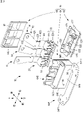
- 3 is an exploded perspective view of the connector shown in FIG. 2.
- FIG. 4 is an exploded perspective view of the connector shown in FIG. 2 viewed from a direction different from that of FIG. 3.
- FIG. 5 is an exploded perspective view of the mating connector shown in FIG. 2.
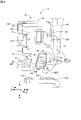
- FIG. FIG. 6 is an enlarged cross-sectional view of the connector cut along the cutting line indicated by arrows VI-VI in FIG.
- FIG. 7 is an enlarged cross-sectional view of the connector cut along the cutting line indicated by arrows VII--VII in FIG.
- FIG. 8 is a perspective view showing a state before connection between the terminal module of the connector and the mating terminal of the mating connector according to the present embodiment.
- FIG. 9 is a perspective view showing a connection state between the terminal module of the connector and the mating terminal of the mating connector according to the present embodiment.
- 10 is a perspective view of the main body of the connector shown in FIG. 3.
- FIG. 11 is a perspective view of the first lid portion of the connector shown in FIG. 3.
- An object of the present disclosure is to provide a connector that can improve durability.
- a connector of the present disclosure is a connector that can be fitted with a mating connector that relatively approaches along a first direction from one side to the other side and that can be electrically connected to the mating connector.
- a terminal module electrically connected to the mating connector and a connector housing accommodating the terminal module, the terminal module including a ceiling wall and a pair of side walls extending from the ceiling wall to the one side.
- an elastic member accommodated in the case and elastically deformable along the first direction; and supported by the pair of side walls while being urged toward the one side by the elastic member.
- first terminal movable to the other side by being pressed by the mating connector; a second terminal positioned on the other side of the first terminal and held by the connector housing; a flexible conductor electrically connecting the first terminal and the second terminal, wherein the flexible conductor includes a first joint portion that joins the first terminal and a first joint portion that joins the second terminal; the connector housing has a body portion for holding the terminal module; and a first lid portion attached to the body portion and facing the flexible conductor; The first lid portion has a bulging portion that bulges toward the side opposite to the flexible conductor, and the flexible conductor is positioned inside the bulging portion in a mating state with the mating connector. can enter.
- the first lid portion facing the flexible conductor has a bulging portion that bulges toward the side opposite to the flexible conductor.
- the flexible conductor can enter inside the bulge. Therefore, compared with the case where the bulging portion is not provided on the first lid portion, it is possible to suppress the wear of the flexible conductor due to contact with the first lid portion. Therefore, the durability of the connector can be improved.
- the bulging portion is arranged on the other side of the first joint portion.
- the bulging portion is arranged on the other side of the first joint portion.
- the flexible conductor can swing in a section between a first joint portion that is a joint portion between the flexible conductor and the first terminal and a second joint portion that is a joint portion between the flexible conductor and the second terminal. .
- the mating connector and the connector move the first terminal to the other side. That is, the oscillating section of the flexible conductor in the first direction is shifted to the other side. Therefore, the swinging section of the flexible conductor in the first direction is shorter in the mated state than in the unmated state.
- the bulging portion is arranged closer to the one side than the second joint portion.
- the bulging portion is arranged on one side of the second joint portion.
- the flexible conductor can swing in a section between a first joint portion that is a joint portion between the flexible conductor and the first terminal and a second joint portion that is a joint portion between the flexible conductor and the second terminal.
- the second terminal is held by the connector housing while the first terminal is movable to the other side. Therefore, the connector can be made more compact while suppressing abrasion of the flexible conductor, compared to the case where the bulging portion overlaps the second joint portion when viewed from the direction orthogonal to the first direction. Therefore, it is possible to both improve the durability of the connector and suppress the enlargement thereof.
- the main body portion of the connector housing has an opposing wall facing the flexible conductor, the opposing wall has a recess recessed toward the opposite side of the flexible conductor, and the flexible It is preferable that the conductor is able to enter the recess in the mated state with the mating connector.
- the facing wall that faces the flexible conductor has a recess that is recessed toward the side opposite to the flexible conductor. Furthermore, a flexible conductor can enter inside the recess. Therefore, compared with the case where the concave portion is not provided in the facing wall, it is possible to suppress the wear of the flexible conductor due to contact with the facing wall. Therefore, the durability of the connector can be improved.
- the recess is arranged on the other side of the first joint portion.
- the concave portion is arranged on the other side of the first joint portion.
- the flexible conductor can swing in a section between a first joint portion that is a joint portion between the flexible conductor and the first terminal and a second joint portion that is a joint portion between the flexible conductor and the second terminal.
- the mating connector and the connector move the first terminal to the other side. That is, the oscillating section of the flexible conductor in the first direction is shifted to the other side. Therefore, the swinging section of the flexible conductor in the first direction is shorter in the mated state than in the unmated state.
- the connector in the non-fitted state of the connector and the mating connector, compared to the case where the concave portion overlaps the first joint portion when viewed from the direction orthogonal to the first direction, the connector can be secured while suppressing abrasion of the flexible conductor. It can be made smaller. As a result, it is possible to both improve the durability of the connector and suppress its enlargement.
- the recess is arranged on the one side of the second joint.
- the concave portion is arranged on one side of the second joint portion.
- the flexible conductor can swing in a section between a first joint portion that is a joint portion between the flexible conductor and the first terminal and a second joint portion that is a joint portion between the flexible conductor and the second terminal.
- the second terminal is held by the connector housing while the first terminal is movable to the other side. Therefore, the connector can be made more compact while suppressing abrasion of the flexible conductor, compared to the case where the concave portion overlaps the second joint portion when viewed from the direction orthogonal to the first direction. Therefore, it is possible to both improve the durability of the connector and suppress the enlargement thereof.
- the recess has a first inclined surface that inclines toward the one side as it approaches the flexible conductor.
- the recess has a first inclined surface that inclines toward one side as it approaches the flexible conductor. Therefore, abrasion of the flexible conductor can be suppressed as compared with the case where the first inclined surface is not provided. Therefore, the durability of the connector can be improved.
- the recess has a second inclined surface that is inclined toward the other side as it approaches the flexible conductor.
- the recess has a second inclined surface that inclines toward the other side as it approaches the flexible conductor. Therefore, abrasion of the flexible conductor can be suppressed as compared with the case where the second inclined surface is not provided. Therefore, the durability of the connector can be improved.
- the bulging portion overlaps the recess when viewed from a direction perpendicular to the first direction and the direction in which the pair of side walls face each other.
- the bulging portion overlaps the concave portion when viewed from a direction perpendicular to the direction in which the pair of side walls face each other and the first direction. Therefore, when the flexible conductor swings, the connector housing has a section in which the flexible conductor can enter both the bulge and the recess in the first direction. Therefore, it is possible to suppress the wear of the flexible conductor due to contact with the connector housing. Therefore, the durability of the connector can be further improved.
- the flexible conductor is arranged between the bulging portion and the recess when viewed from the direction in which the pair of side walls face each other.
- the flexible conductor is arranged between the bulging portion and the recess when viewed from the direction in which the pair of side walls face each other.
- the flexible conductor is sandwiched between the bulge and the recess. Therefore, even if the flexible conductor swings toward either the bulging portion side or the recessed portion side, it is possible to prevent the flexible conductor from coming into contact with the connector housing and being worn. Therefore, the durability of the connector can be improved.
- the connector 10 and the mating connector 12 are provided on equipment (not shown) mounted on the vehicle.
- the connector 10 is provided in a PCU (Power Control Unit, an example of equipment) including an inverter circuit
- the mating connector 12 is provided in a motor (an example of mating equipment).
- the mating connector 12 is inserted into the connector 10 by relatively approaching the connector 10 along the first direction from one side to the other side. That is, the connector 10 and the mating connector 12 are fitted together, and the connector 10 and the mating connector 12 are electrically connected.
- the PCU and the motor are electrically connected via the connector 10 and the mating connector 12 .
- the fitting between the connector 10 and the mating connector 12 will be described later.
- Connector 10 includes terminal module 14 and connector housing 16 .
- the terminal module 14 is a module for electrically connecting the mating terminal 124 included in the mating connector 12 and an electric circuit (not shown) included in the device.
- the connector housing 16 accommodates the terminal module 14.
- the connector housing 16 has a body portion 64 , a first lid portion 66 and a second lid portion 68 .
- the terminal module 14 is housed in the space between the body portion 64 and the first lid portion 66 and the second lid portion 68 .
- the terminal module 14, the body portion 64, and the first lid portion 66 are arranged in a direction orthogonal to the first direction.
- the main body portion 64 and the second lid portion 68 are arranged along the first direction.
- the terminal module 14 includes a case 20, an elastic member 18, first terminals 22, second terminals 42, and flexible conductors 44. As shown in FIGS. The configuration of each part of the terminal module 14 described below is the configuration of the connector 10 in the unmated state.
- the case 20 has a ceiling wall 24 , a pair of side walls 26 , 26 extending from the ceiling wall 24 , and a pair of elastic member holding walls 28 , 28 extending from the ceiling wall 24 .
- the case 20 is made of metal, for example.
- the case 20 is made of stainless steel, for example.
- the case 20 accommodates the elastic member 18 .
- a ceiling wall 24, a pair of side walls 26, 26, and a pair of elastic member holding walls 28, 28 are integrally formed by pressing a plate material.
- a pair of side walls 26, 26 face each other.
- the direction in which the pair of side walls 26, 26 face each other is orthogonal to the first direction.
- the direction in which the pair of side walls 26, 26 face each other is orthogonal to the direction in which the main body portion 64 and the first lid portion 66 are arranged.
- the direction along the first direction will be referred to as the vertical direction.
- the facing direction of the pair of side walls 26, 26 is called the lateral direction.
- a direction orthogonal to the first direction and the opposing direction of the pair of side walls 26, 26 is referred to as the front-rear direction. That is, the direction in which the main body portion 64 and the first lid portion 66 are arranged is referred to as the front-rear direction.
- the other side will be referred to as the upper side, and the one side will be referred to as the lower side.
- the body portion 64 side is referred to as the front
- the first lid portion 66 side is referred to as the rear.
- the ceiling wall 24 is a flat plate-shaped area provided along the front-rear direction and the left-right direction.
- the widths of the ceiling wall 24 in the front-rear direction and the left-right direction are larger than the widths of the elastic member 18 in the front-rear direction and the left-right direction.
- the ceiling wall 24 covers the elastic member 18 when viewed from above in the vertical direction.
- the pair of side walls 26 , 26 are a pair of walls parallel to each other extending downward from the lateral edges of the ceiling wall 24 .
- the pair of side walls 26, 26 each have a mirror-symmetrical shape.
- the right side wall 26 will be representatively described below.
- the side wall 26 has a base portion 26A, a first leg portion 26B, a second leg portion 26C, and a guide projection 26D.
- the base 26A is connected to the ceiling wall 24. 26 A of bases have the same width as the ceiling wall 24 in the front-back direction.
- the base portion 26A has a function of receiving the elastic member 18 that bends in the left-right direction when the elastic member 18 is compressed or stretched.
- the first leg portion 26B extends downward from the base portion 26A and inclines forward at the central portion in the front-rear direction of the base portion 26A.
- the width of the first leg portion 26B in the vertical direction is longer than the width of the inclination in the front-rear direction.
- the first leg portion 26B has a smaller width than the base portion 26A in the front-rear direction.
- the first leg portion 26B has a width of, for example, about one quarter of the width of the base portion 26A.
- the first leg portion 26B has a first receiving portion 26B1 extending forward at its lower end portion.
- the upper surface of the first receiving portion 26B1 is a surface extending along the front-rear direction.
- a rear surface of the first leg portion 26B functions as a guide surface 26B2 that guides the first terminal 22 when the mating connector 12 is mated. Since the guide surface 26B2 extends downward while being inclined in the front-rear direction, the first terminal 22 is guided not only in the vertical direction but also in the front-rear direction along the guide surface 26B2.
- the second leg portion 26C extends downward from the base portion 26A.
- the second leg 26C is located behind the first leg 26B.
- the second leg 26C is separated from the first leg 26B in the front-rear direction.
- the second leg portion 26C has a width smaller than that of the base portion 26A in the front-rear direction.
- the second leg portion 26C has, for example, about a quarter of the width of the base portion 26A.
- the second leg portion 26C has a second receiving portion 26C1 and a lower end portion 26C2.
- the second receiving portion 26C1 is arranged above the lower end portion 26C2.
- the second receiving portion 26C1 protrudes rearward from the lower end portion 26C2.
- the upper surface of the second receiving portion 26C1 is a surface extending along the front-rear direction.
- the guide protrusion 26D protrudes rightward from the base 26A.
- the guide protrusion 26D protrudes from the base portion 26A toward the side opposite to the elastic member 18.
- the guide protrusion 26D is formed by bending a portion of the side wall 26 rightward.
- the guide projection 26D is formed by bending the side wall 26 rightward between a pair of slits 27, 27, and the slits 27, 27 are provided on both upper and lower sides of the guide projection 26D. , the guide projection 26D can be easily bent rightward.
- the guide projection 26D is arranged above the first leg 26B.
- the guide projection 26D is arranged above the second leg portion 26C.
- One guide projection 26D is provided on the front side of the side wall 26 and one on the rear side of the side wall 26.
- the guide projection 26D arranged in front of the side wall 26 and the guide projection 26D arranged in the rear of the side wall 26 overlap each other when viewed from the front-rear direction.
- the position of the upper surface of the guide projection 26D arranged in front of the side wall 26 is equal to the position of the upper surface of the guide projection 26D arranged in the rear of the side wall 26.
- the position of the lower surface of the guide projection 26D arranged in front of the side wall 26 is equal to the position of the lower surface of the guide projection 26D arranged in the rear of the side wall 26.
- the pair of elastic member holding walls 28 , 28 are a pair of parallel walls extending downward from the edges of the ceiling wall 24 in the front-rear direction.
- the pair of elastic member holding walls 28, 28 has a width smaller than that of the ceiling wall 24 in the left-right direction.
- the pair of elastic member holding walls 28, 28 has a width of, for example, about one-third of the width of the ceiling wall 24 in the left-right direction.
- the pair of elastic member holding walls 28, 28 has a smaller width than the side wall 26 in the vertical direction.
- the pair of elastic member holding walls 28, 28 has, for example, about half the width of the side wall 26 in the vertical direction. As shown in FIG.
- the inner surfaces of the pair of elastic member holding walls 28, 28 in the front-rear direction face the side portions of the elastic member 18 in the front-rear direction with a slight gap therebetween.
- the pair of elastic member holding walls 28, 28 has the function of receiving the elastic member 18 that bends in the front-rear direction when the elastic member 18 is compressed or stretched.
- the elastic member 18 is a coil spring in which a metal wire is wound in a coil shape.
- the elastic member 18 is made of stainless steel, for example.
- the elastic member 18 is housed in the case 20. That is, the elastic member 18 is surrounded by a ceiling wall 24, a pair of side walls 26, 26, and a pair of elastic member holding walls 28, 28. As shown in FIG. The elastic member 18 is sandwiched between the ceiling wall 24 and the first terminal 22 while being vertically compressed. The elastic member 18 biases the first terminal 22 downward. The elastic member 18 urges the ceiling wall 24 upward. In this state, the elastic member 18 can be further compressed in the vertical direction. That is, the elastic member 18 is compressed by the ceiling wall 24 and the first terminal 22 in a range shorter than the free length of the spring and longer than the maximum compressed length.
- the elastic member 18 has a first end 18a and a second end 18b.
- the first end portion 18a is a region extending from the upper end of the elastic member 18 for about one turn.
- the first end 18 a is in contact with the ceiling wall 24 .
- the second end portion 18b is an area extending from the lower end of the elastic member 18 by about one turn.
- the second end 18 b is in contact with the first terminal 22 .
- the first terminal 22 is a terminal capable of physically contacting the mating terminal 124 .
- the first terminal 22 is attached to a pair of side walls 26,26.
- the first terminal 22 is supported by the pair of side walls 26 , 26 while being biased downward by the elastic member 18 .
- the first terminal 22 has a first portion 22a, a second portion 22b, a first surface 22A, and a second surface 22B arranged opposite to the first surface 22A.
- the first terminal 22 is made of metal.
- the first terminal 22 is made of, for example, a copper alloy.
- the first terminal 22 has a first portion 22a and a second portion 22b integrally formed by pressing a plate material.
- the first portion 22a is arranged downwardly away from the ceiling wall 24 .
- the first portion 22 a is provided parallel to the ceiling wall 24 . That is, the first portion 22a extends along the front-rear direction and the left-right direction.
- the second portion 22b extends upward from the rear edge of the first portion 22a. Therefore, the first terminal 22 has an L shape when viewed in the horizontal direction.
- the first portion 22 a has a pair of first engaging portions 58 , 58 and a pair of guided portions 62 , 62 .
- the second portion 22b has a pair of second engaging portions 60,60.
- the first surface 22A of the first portion 22a is in contact with the second end 18b of the elastic member 18.
- the first surface 22A of the first portion 22a functions as a receiving surface for receiving the second end 18b of the elastic member 18.
- the second surface 22B of the first portion 22a functions as a contact surface capable of contacting the mating contact 128 included in the mating terminal 124 .
- the first engaging portion 58 protrudes outward in the left-right direction from the front edge of the first portion 22a.
- the first engaging portion 58 contacts the first receiving portion 26B1 of the first leg portion 26B from above.
- the first engaging portion 58 contacts the upper surface of the first receiving portion 26B1.
- the first engaging portion 58 is received by the first receiving portion 26B1.
- the guided portion 62 protrudes outward in the left-right direction at the central portion in the front-rear direction of the first portion 22a.
- the guided portion 62 is inserted between the first leg portion 26B and the second leg portion 26C.
- the guided portion 62 is guided vertically and longitudinally along the guide surface 26B2.
- the first surface 22A of the second portion 22b faces the elastic member 18 side.
- a second surface 22B of the second portion 22b is a surface facing away from the elastic member 18 .
- a flexible conductor 44 is connected to the second surface 22B of the second portion 22b.
- the second engaging portion 60 protrudes outward in the left-right direction.
- the second engaging portion 60 is arranged below the center portion in the vertical direction of the second portion 22b.
- the second engaging portion 60 contacts the second receiving portion 26C1 of the second leg portion 26C from above.
- the second engaging portion 60 contacts the upper surface of the second receiving portion 26C1.
- the second engaging portion 60 is received by the second receiving portion 26C1.
- the downward movement of the first terminal 22 is restricted by the contact of the first engaging portion 58 with the first receiving portion 26B1 and the contact of the second engaging portion 60 with the second receiving portion 26C1. That is, in the non-fitted state, the first terminal 22 is held between the elastic member 18 and the pair of side walls 26 , 26 . In the non-fitted state, the first terminal 22 is sandwiched between the elastic member 18 and the pair of first receiving portions 26B1, 26B1 and the pair of second receiving portions 26C1, 26C1.
- the second terminal 42 is a flat terminal electrically connected to an electrical circuit (not shown) included in the PCU.
- the second terminal 42 has an upper portion 42A, a lower portion 42B and a constricted portion 42C.
- the second terminal 42 is made of metal.
- the second terminal 42 is made of copper alloy, for example.
- the second terminal 42 is integrally formed with an upper portion 42A, a lower portion 42B, and a constricted portion 42C by pressing a plate material.
- a second terminal 42 is attached to the connector housing 16 .
- the second terminal 42 is held above the first terminal 22 by the connector housing 16 .
- the upper portion 42A is arranged outside the connector housing 16.
- the upper portion 42A is a region connected to an electric circuit (not shown).
- the lower portion 42B extends downward from the upper portion 42A.
- Lower portion 42B is located inside connector housing 16 .
- a flexible conductor 44 is connected to the lower portion 42B.
- the constricted portion 42C is a region recessed inward in the left-right direction in the boundary region between the upper portion 42A and the lower portion 42B. The constricted portion 42C fits with the connector housing 16 in a concave-convex manner.
- the flexible conductor 44 is a flexible conductor. As shown in FIG. 7, the flexible conductor 44 electrically connects the first terminal 22 and the second terminal 42 .
- the flexible conductor 44 is a conductor that is more flexible than the first terminal 22 .
- the flexible conductor 44 is a conductor that is more flexible than the second terminal 42 .
- Flexible conductor 44 is repeatedly deformable.
- the flexible conductor 44 is, for example, a strip-shaped braided wire in which a plurality of conductive metal wires are woven.
- the braided wire is formed, for example, by weaving strands of copper alloy.
- the flexible conductor 44 has a first joint portion 52 joined to the first terminal 22 , a second joint portion 48 joined to the second terminal 42 , the first joint portion 52 and the second joint portion 48 . and an intermediate portion 53 between.
- the first joint portion 52 is joined to the first terminal 22 by resistance welding.
- the first joint portion 52 is joined to the second portion 22b of the first terminal 22 by resistance welding, for example.
- the first joint portion 52 has higher rigidity than the intermediate portion 53 .
- the second joint portion 48 is joined to the second terminal 42 by resistance welding.
- the second joint portion 48 is joined to the lower portion 42B of the second terminal 42 by resistance welding, for example.
- the second joint portion 48 has higher rigidity than the intermediate portion 53 .
- the second portion 22b of the first terminal 22 and the second terminal 42 are arranged vertically. That is, the first joint portion 52 and the second joint portion 48 are arranged in the vertical direction. Among the first joint portion 52 , the second joint portion 48 and the intermediate portion 53 , the first joint portion 52 is arranged at the lowest position. Among the first joint portion 52 , the second joint portion 48 and the intermediate portion 53 , the second joint portion 48 is arranged at the uppermost position.
- the connector housing 16 has a body portion 64, a first lid portion 66, and a second lid portion 68. As shown in FIGS. Connector housing 16 houses terminal module 14 . Connector housing 16 accommodates three terminal modules 14 in this embodiment. A reinforcing member 64F is attached to the body portion 64 . The first lid portion 66 is attached to the rear of the body portion 64 . The second lid portion 68 is attached below the body portion 64 and the first lid portion 66 .
- the body portion 64 is made of thermoplastic resin, for example.
- the body portion 64 has a front wall 64A, a right wall 64B, a left wall 64C, a support wall 64D and an upper wall 64E.
- the front wall 64A, the right wall 64B, the left wall 64C, the support wall 64D and the upper wall 64E are integrally formed by injection molding, for example.
- the front wall 64A is a wall arranged in front of the case 20.
- the right wall 64B is a wall extending rearward from the right edge of the front wall 64A.
- the left wall 64C is a wall extending rearward from the left edge of the front wall 64A.
- the support wall 64D is a wall arranged above the case 20 .
- the support wall 64D continues to the front wall 64A, the right wall 64B and the left wall 64C.
- the upper wall 64E is a wall extending upward from the rear edge of the support wall 64D.
- the support wall 64D is arranged above the ceiling wall 24 of the case 20.
- the support wall 64D has a contact surface 64D1 and a reinforcing surface 64D2 arranged on the opposite side of the contact surface 64D1.
- the contact surface 64D1 faces the case 20.
- the contact surface 64D1 faces the ceiling wall 24. As shown in FIG.
- the contact surface 64D1 can contact with the case 20 .
- the contact surface 64D1 can contact the ceiling wall 24 .
- the body portion 64 includes a terminal module housing portion 70 for housing the terminal module 14, a partition wall 71, a first opening portion 75, a second opening portion 77, and a holding portion. 82 and a first engaging projection 84 .
- the first opening 75 is formed by opening the rear of the main body 64 .
- the first opening 75 exposes the terminal module accommodating portion 70 to the outside of the main body portion 64 . Therefore, the body portion 64 can house the terminal module 14 in the terminal module housing portion 70 from behind, for example.
- the second opening 77 is formed by opening the bottom of the main body 64 .
- the second opening 77 exposes the terminal module accommodating portion 70 to the outside of the main body portion 64 .
- the terminal module housing portion 70 has a case housing portion 72 and a flexible conductor housing portion 74 .
- the terminal module accommodating portion 70 extends along the vertical direction.
- the terminal module housing portion 70 is an internal space of the body portion 64 .
- a plurality of terminal module housing portions 70 are provided along the left-right direction.
- a plurality of terminal module accommodating portions 70 are formed by partitioning the internal space of the main body portion 64 with partition walls 71 .
- the plurality of terminal module housing portions 70 individually house the plurality of terminal modules 14 .
- the three terminal module accommodating portions 70 are arranged in the left-right direction.
- the partition wall 71 extends in the vertical direction and the front-rear direction.
- the partition wall 71 continues to the front wall 64A, the support wall 64D and the upper wall 64E.
- the partition wall 71 defines a space for individually accommodating the plurality of terminal modules 14 in the body portion 64 . That is, the partition walls 71 are arranged between the adjacent terminal module accommodating portions 70 .
- two partition walls 71 are provided to form three terminal module housing portions 70 . That is, in this embodiment, two partition walls 71 are arranged in the horizontal direction.
- the partition wall 71 is arranged between the case accommodating portions 72 adjacent in the left-right direction. That is, the partition 71 is arranged between the cases 20 adjacent in the left-right direction. The partition 71 faces the case 20 in the left-right direction.
- the partition wall 71 is arranged between the flexible conductor accommodating portions 74 adjacent to each other in the left-right direction. That is, the partition 71 is arranged between the flexible conductors 44 adjacent in the left-right direction. The partition 71 faces the flexible conductor 44 in the left-right direction.
- the partition wall 71 has guide rails 99 extending in the vertical direction.
- the guide rail 99 is, for example, a groove extending in the vertical direction.
- a guide rail 99 is provided on the rear surface of the partition wall 71 .
- a rear surface of the partition wall 71 faces the first lid portion 66 .
- the guide rail 99 faces the first lid portion 66 .
- the case accommodating portion 72 accommodates the case 20 of the terminal module 14 .
- the case accommodating portion 72 is arranged below the flexible conductor accommodating portion 74 .
- the case accommodating portion 72 faces the case 20 .
- the rear side of the case accommodating portion 72 is opened by a first opening portion 75 .
- a second opening 77 opens below the case accommodating portion 72 .
- three case accommodating portions 72 are arranged in the left-right direction.
- the rightmost case accommodating portion 72 is partitioned by a front wall 64A, a right wall 64B, a support wall 64D, and a partition wall 71.
- the leftmost case accommodating portion 72 is partitioned by a front wall 64A, a left wall 64C, a support wall 64D and a partition wall 71.
- a case accommodating portion 72 in the middle in the left-right direction is partitioned by a front wall 64A, a support wall 64D, and a pair of partition walls 71, 71.
- the case accommodating portion 72 has a guide groove 76 that regulates the moving direction of the terminal module 14 .
- the guide grooves 76 are provided in the right wall 64B, the left wall 64C and the partition wall 71 .
- the guide groove 76 extends along the front-rear direction.
- the guide groove 76 faces the case 20 .
- the guide groove 76 faces the pair of side walls 26 , 26 .
- the guide protrusion 26D of the case 20 is inserted into the guide groove 76, and the guide groove 76 holds the guide protrusion 26D.
- the guide projection 26D is locked in the guide groove 76.
- the guide projections 26D provided on the pair of side walls 26, 26 are slidable in the guide grooves 76.
- the terminal module 14 is slidable along the guide grooves 76 .
- the flexible conductor housing portion 74 houses the flexible conductor 44 of the terminal module 14 .
- the flexible conductor accommodating portion 74 is arranged above the case accommodating portion 72 .
- the flexible conductor accommodating portion 74 continues with the case accommodating portion 72 .
- the flexible conductor accommodating portion 74 is arranged on the upper wall 64E.
- the flexible conductor accommodating portion 74 faces the flexible conductor 44 .
- the rear side of the flexible conductor accommodating portion 74 is opened by a first opening portion 75 .
- the flexible conductor accommodating portion 74 has a facing wall 79 facing the flexible conductor 44 and a recess 78 formed in the facing wall 79 .
- the recess 78 faces the flexible conductor 44 .
- the recess 78 is recessed toward the side opposite to the flexible conductor 44 .
- the flexible conductor 44 can enter the interior space of the recess 78 .
- the concave portion 78 is arranged above the first joint portion 52 . That is, the concave portion 78 is arranged on the other side of the first joint portion 52 .
- the recess 78 is arranged below the second joint portion 48 . That is, the concave portion 78 is arranged on one side of the second joint portion 48 .
- the recess 78 has a first inclined surface 78A and a second inclined surface 78B.
- the first inclined surface 78A is inclined downward toward the rear. That is, the first inclined surface 78A is inclined toward one side as it approaches the flexible conductor 44 .
- the second inclined surface 78B is inclined upward toward the rear. That is, the second inclined surface 78B is inclined toward the other side as it approaches the flexible conductor 44 .
- the first inclined surface 78A is arranged above the second inclined surface 78B.
- the holding portion 82 holds the second terminal 42 so as to be arranged above the first terminal 22 .
- the holding portion 82 is engaged with the constricted portion 42C of the second terminal 42 in a concave-convex manner.
- the holding portion 82 is arranged on the upper wall 64E.
- the holding portion 82 is arranged above the case accommodating portion 72 .
- the holding portion 82 is arranged above the flexible conductor accommodating portion 74 .
- the first engagement projection 84 engages with the second lid portion 68 .
- the first engaging projection 84 is provided on the front wall 64A of the main body portion 64 .
- the first engaging projection 84 is arranged below the front wall 64A. In this embodiment, a plurality of first engaging projections 84 are provided.
- the reinforcing member 64F is a plate-shaped member extending in the left-right direction, as shown in FIGS.
- the reinforcing member 64F is made of stainless steel, for example.
- the reinforcing member 64F is superior in rigidity to the connector housing 16. As shown in FIG.
- the reinforcing member 64F has higher rigidity than the supporting wall 64D.
- the reinforcing member 64F is attached to the connector housing 16.
- the reinforcing member 64F is attached to the body portion 64 .
- the reinforcing member 64F is attached to the support wall 64D.
- the reinforcement member 64F is in contact with the reinforcement surface 64D2 of the support wall 64D.
- the reinforcing member 64F is integrated with the connector housing 16. At least part of the reinforcing member 64F is embedded in the connector housing 16 .
- the reinforcing member 64F is integrated with the connector housing 16 by insert molding, for example.
- the reinforcing member 64F is integrated with the body portion 64 .
- the reinforcing member 64F is integrated with the body portion 64 . At least a portion of the reinforcing member 64F is embedded in the body portion 64. As shown in FIG.
- the reinforcing member 64F is integrated with the support wall 64D by insert molding, for example.
- the reinforcing member 64F overlaps the support wall 64D when viewed from above in the vertical direction.
- the reinforcing member 64F overlaps the contact surface 64D1 when viewed from above in the vertical direction.
- the reinforcing member 64F overlaps the ceiling wall 24 of the case 20 of the terminal module 14 when viewed from above in the vertical direction. In the present embodiment, the reinforcing member 64F overlaps all of the ceiling walls 24 of the three terminal modules 14 aligned in the horizontal direction when viewed from above in the vertical direction.
- the reinforcing member 64F has a fixing portion 64F1 capable of fixing the connector 10 to the housing of the PCU.
- the fixing portions 64F1 are provided on both sides in the left-right direction of the reinforcing member 64F.
- First lid portion 66 As shown in FIGS. 2, 3, 4, and 7, the first lid portion 66 is attached to the body portion 64. As shown in FIGS. The first lid portion 66 covers the first opening portion 75 of the body portion 64 . The first lid portion 66 faces the flexible conductor 44 . The first lid portion 66 is slidable with respect to the body portion 64 . More specifically, the first lid portion 66 is slidable along the vertical direction with respect to the main body portion 64 . The first lid portion 66 has a bulging portion 102 , a second engaging projection 108 and a guide projecting piece 117 .
- the bulging portion 102 faces the flexible conductor 44 .
- the bulging portion 102 faces the flexible conductor 44 in the front-rear direction.
- the bulging portion 102 bulges to the side opposite to the flexible conductor 44 .
- the bulging portion 102 bulges rearward.
- the bulging portion 102 is arranged above the first joint portion 52 . That is, the bulging portion 102 is arranged on the other side of the first joint portion 52 .
- the bulging portion 102 is arranged below the second joint portion 48 . That is, the bulging portion 102 is arranged on one side of the second joint portion 48 .
- the flexible conductor 44 can enter inside the bulging portion 102 .
- the bulging portion 102 overlaps the recessed portion 78 when viewed from the front-rear direction. That is, the bulging portion 102 overlaps the recessed portion 78 when viewed from a direction perpendicular to the direction in which the pair of side walls 26, 26 face each other and the first direction.
- the bulging portion 102 is located on the side opposite to the recessed portion 78 with respect to the flexible conductor 44 when viewed from the left-right direction.
- the bulging portion 102 and the recessed portion 78 are located on both front and rear sides of the flexible conductor 44 . That is, the flexible conductor 44 is arranged between the bulging portion 102 and the recessed portion 78 when viewed from the direction in which the pair of side walls 26 , 26 face each other.
- the second engaging projection 108 engages with the second lid portion 68 .
- the second engaging projection 108 is provided on the rear surface of the first lid portion 66 . That is, the second engaging projection 108 is provided on the surface of the second lid portion 68 opposite to the surface facing the flexible conductor 44 .
- the second engaging projection 108 is provided below the first lid portion 66 .
- the second engaging projection 108 is arranged below the bulging portion 102 . In this embodiment, two second engaging projections 108 are provided.
- the guide projecting piece 117 is provided on the front surface of the second lid portion 68 .
- the guide projecting piece 117 protrudes forward.
- the guide projecting piece 117 extends in the vertical direction and is slidable along the guide rail 99 .
- the guide projecting piece 117 fits into the guide rail 99 of the body portion 64 .
- the guide protrusion 117 enables the first lid portion 66 to slide relative to the main body portion 64 along the guide rails 99 .
- Two guide protrusions 117 are provided in this embodiment.
- the second lid portion 68 is attached to the body portion 64 and the first lid portion 66 .
- the second lid portion 68 is attached to the lower side of the main body portion 64 .
- the second lid portion 68 is attached to the lower side of the first lid portion 66 .
- the second lid portion 68 covers the second opening portion 77 of the body portion 64 .
- the second lid portion 68 has a first engagement piece 120 that engages with the body portion 64 and a second engagement piece that engages with the first lid portion 66. It has a mating piece 121 and a mating terminal insertion hole 122 which is open in the vertical direction.
- the first engagement piece 120 engages with the lower portion of the front wall 64A.
- the first engaging piece 120 engages with the first engaging projection 84 of the front wall 64A.
- the second engaging piece 121 engages with the lower portion of the first lid portion 66 .
- the second engaging piece 121 engages with the second engaging protrusion 108 of the first lid portion 66 .
- the second engaging piece 121 is arranged on the side opposite to the first engaging piece 120 .
- the second engaging piece 121 is arranged below the bulging portion 102 .
- the second engaging piece 121 overlaps the bulging portion 102 when viewed from above.
- the mating terminal insertion hole 122 overlaps the second opening 77 of the main body 64 .
- the mating terminal insertion hole 122 exposes the terminal module 14 to the outside of the second lid portion 68 .
- the mating terminal insertion hole 122 exposes the first terminal 22 of the terminal module 14 to the outside of the second lid portion 68 .
- the mating terminal insertion hole 122 allows the mating terminal 124 to enter from below and allow the mating terminal 124 and the first terminal 22 to physically contact each other.
- the mating terminal insertion holes 122 are provided so as to correspond to the number of the terminal modules 14 accommodated in the connector housing 16 . In this embodiment, three mating terminal insertion holes 122 are provided.
- the mating connector 12 has a mating terminal 124 and a mating housing 126, as shown in FIG.
- the mating terminal 124 is held by a mating housing 126 . At least part of the mating terminal 124 is embedded in the mating housing 126 .
- the mating terminal 124 is provided by, for example, insert molding.
- the mating terminal 124 is a conductive metal member.
- the mating terminal 124 is made of, for example, a copper alloy.
- Mating terminal 124 includes a region extending in the vertical direction and a region extending forward from the region.
- the mating terminal 124 has an L shape when viewed from the left-right direction.
- the mating terminal 124 has a mating contact 128 that contacts the second surface 22B of the first portion 22a of the first terminal 22 .
- the mating contact 128 is provided in a bead shape on the upper surface of the mating terminal 124 by partially plastically deforming the mating terminal 124 .
- the mating housing 126 is a member made of resin.
- the mating housing 126 has fitting portions 130 that can be inserted into the mating terminal insertion holes 122 of the connector housing 16 .
- the fitting portion 130 has an upwardly convex shape.
- the fitting portion 130 supports the mating terminal 124 on its upper surface.
- the first terminal 22 When the mating connector 12 moves further upward after the mating contact 128 contacts the second surface 22B, the first terminal 22 is pressed by the mating contact 128, and the first terminal 22 compresses the elastic member 18. while moving upwards. At this time, the guided portion 62 of the first terminal 22 is in sliding contact with the guide surface 26B2 of the first leg portion 26B. Therefore, the first terminal 22 moves upward and also moves rearward by the amount that the guide surface 26B2 is inclined in the front-rear direction. Since the width of the guide surface 26B2 in the vertical direction is longer than the width of the guide surface 26B2 inclined in the front-rear direction, the amount of upward movement of the first terminal 22 during fitting is greater than the amount of backward movement.
- the second surface 22B of the first terminal 22 that moves rearward slides in the front-rear direction on the mating contact 128 that moves upward.
- foreign matter adhering between the second surface 22B and the mating contact 128 is removed.
- the foreign matter include films such as sulfides and oxides formed on the surface of the second surface 22B.
- the first portion 22 a of the first terminal 22 receives a downward biasing force from the elastic member 18 and an upward pressing force from the mating contact 128 .
- the first portion 22 a of the first terminal 22 is vertically sandwiched between the elastic member 18 and the mating contact 128 .
- the first joint portion 52 and the second joint portion 48 move upward as the first terminal 22 moves upward.
- the straight-line distance between becomes shorter. Therefore, as the first terminal 22 moves upward, the flexible conductor 44 is deformed, and the amount of deflection of the flexible conductor 44 increases. Therefore, the flexible conductor 44 tends to swing more easily after the connector 10 and the mating connector 12 are mated than before the connector 10 and the mating connector 12 are mated. That is, the flexible conductor 44 tends to swing more easily when the connector 10 and the mating connector 12 are mated than when the connector 10 and the mating connector 12 are not mated.
- the flexible conductor 44 can enter the bulging portion 102 when the connector 10 and the mating connector 12 are mated.
- the flexible conductor 44 can enter the recess 78 when the connector 10 and the mating connector 12 are mated.
- the case 20 is in contact with the contact surface 64D1.
- the ceiling wall 24 is in contact with the contact surface 64D1.
- the elastic member 18 biases the ceiling wall 24 toward the support wall 64D.
- the elastic member 18 presses the ceiling wall 24 toward the support wall 64D.
- the first terminal 22 is in contact with the mating contact 128 when the connector 10 and the mating connector 12 are mated.
- the elastic member 18 biases the first terminal 22 toward the mating connector 12 in the mated state of the connector 10 and the mating connector 12 .
- the first terminal 22 is pressed toward the mating connector 12 when the connector 10 and the mating connector 12 are mated.
- the first terminal 22 is supported by the mating connector 12 when the connector 10 and the mating connector 12 are mated.
- the first lid portion 66 facing the flexible conductor 44 has a bulging portion 102 that bulges toward the side opposite to the flexible conductor 44 . Furthermore, the flexible conductor 44 can enter inside the bulging portion 102 . Therefore, compared to the case where the bulging portion 102 is not provided on the first lid portion 66 , it is possible to suppress abrasion of the flexible conductor 44 due to contact with the first lid portion 66 . Therefore, durability of the connector 10 can be improved.
- the wear of the flexible conductor 44 is reduced compared to the case where the bulging portion 102 overlaps the first joint portion 52 when viewed from the direction orthogonal to the first direction. while suppressing the enlargement of the connector 10 . As a result, it is possible to both improve the durability of the connector 10 and suppress its enlargement.
- the bulging portion 102 is arranged on one side of the second joint portion 48 .
- the flexible conductor 44 is positioned between a first joint portion 52, which is a joint portion between the flexible conductor 44 and the first terminal 22, and a second joint portion 48, which is a joint portion between the flexible conductor 44 and the second terminal 42. can oscillate in the interval of Further, the second terminal 42 is held by the connector housing 16 while the first terminal 22 is movable to the other side. Therefore, as compared with the case where the bulging portion 102 overlaps the second joint portion 48 when viewed from the direction orthogonal to the first direction, it is possible to suppress the wear of the flexible conductor 44 and the enlargement of the connector 10 . Therefore, it is possible to both improve the durability of the connector 10 and suppress its enlargement.
- the facing wall 79 that faces the flexible conductor 44 has a concave portion 78 that is recessed toward the side opposite to the flexible conductor 44 . Further, the flexible conductor 44 can enter inside the recess 78 . Therefore, compared with the case where the concave portion 78 is not provided in the facing wall 79 , it is possible to suppress the wear of the flexible conductor 44 due to contact with the facing wall 79 . Therefore, durability of the connector 10 can be improved.
- the concave portion 78 is arranged on the other side of the first joint portion 52 .
- Flexible conductor 44 can swing in the section between first joint 52 , flexible conductor 44 and second joint 48 .
- the first terminal 22 moves to the other side. That is, the swing section of the flexible conductor 44 in the first direction is shifted to the other side. Therefore, the swing section of the flexible conductor 44 in the first direction is shorter in the fitted state than in the unfitted state.
- the abrasion of the flexible conductor 44 is suppressed as compared with the case where the concave portion 78 overlaps the first joint portion 52 when viewed from the direction orthogonal to the first direction.
- enlargement of the connector 10 can be suppressed. As a result, it is possible to both improve the durability of the connector 10 and suppress its enlargement.
- the concave portion 78 is arranged on one side of the second joint portion 48 .
- Flexible conductor 44 can swing in the section between first joint 52 and second joint 48 .
- the second terminal 42 is held by the connector housing 16 while the first terminal 22 is movable to the other side. Therefore, the connector 10 can be made more compact while suppressing abrasion of the flexible conductor 44, compared to the case where the concave portion 78 overlaps the second joint portion 48 when viewed from the direction perpendicular to the first direction. Therefore, it is possible to both improve the durability of the connector 10 and suppress its enlargement.
- the concave portion 78 has a first inclined surface 78A that inclines toward one side as the flexible conductor 44 is approached. Therefore, abrasion of the flexible conductor 44 can be suppressed as compared with the case where the first inclined surface 78A is not provided. Therefore, durability of the connector 10 can be improved.
- the concave portion 78 has a second inclined surface 78B that inclines toward the other side as it approaches the flexible conductor 44 . Therefore, abrasion of the flexible conductor 44 can be suppressed as compared with the case where the second inclined surface 78B is not provided. Therefore, durability of the connector 10 can be improved.
- the bulging portion 102 overlaps the recessed portion 78 when viewed from a direction orthogonal to the direction in which the pair of side walls 26, 26 face each other and the first direction. Therefore, when the flexible conductor 44 swings, the connector housing 16 has a section in which the flexible conductor 44 can enter both the bulging portion 102 and the recessed portion 78 in the first direction. Therefore, it is possible to suppress wear of the flexible conductor 44 due to contact with the connector housing 16 . As a result, the durability of the connector 10 can be improved.
- the flexible conductor 44 is arranged between the bulging portion 102 and the recessed portion 78 when viewed from the direction in which the pair of side walls 26, 26 face each other. Flexible conductor 44 is sandwiched between bulging portion 102 and recessed portion 78 . Therefore, even if the flexible conductor 44 swings toward either the bulging portion 102 side or the recessed portion 78 side, the contact of the flexible conductor 44 with the connector housing 16 can be suppressed. Therefore, durability of the connector 10 can be improved.
- the number of terminal modules 14 in the above embodiment is not limited to three, and may be changed to two or less or four or more.
- the connector housing 16 of the above embodiment has the main body portion 64 , the first lid portion 66 and the second lid portion 68 in the above embodiment, it is not limited to this.
- the connector housing 16 only needs to accommodate the terminal module 14 .
- the elastic member 18 of the above-described embodiment may be a member other than the coil spring as long as it is a member that can expand and contract in the vertical direction.
- the elastic member 18 need not be made of stainless steel.
- the elastic member 18 may be, for example, a leaf spring or a rubber member.
- the case 20 of the above embodiment does not have to be made of stainless steel.
- the case 20 may be made of, for example, an iron alloy, a copper alloy, or an aluminum alloy.
- the 1st terminal 22 of the said embodiment does not need to be a product made from a copper alloy.
- the first terminal 22 may be made of, for example, an aluminum alloy.
- the 1st terminal 22 of the said embodiment may be plated.
- the first terminal 22 may be plated with copper tin, for example.
- the 1st terminal 22 of the said embodiment the 1st part 22a and the 2nd part 22b are not integrally formed, and the 2nd part 22b may be abbreviate
- the 2nd terminal 42 of the said embodiment does not need to be a product made from a copper alloy.
- the second terminal 42 may be made of, for example, an aluminum alloy.
- the 2nd terminal 42 of the said embodiment may be plated.
- the second terminal 42 may be plated with copper tin, for example.
- the flexible conductor 44 of the above embodiment is not particularly limited as long as it is a flexible conductor.
- the flexible conductor 44 may be, for example, a tubular braided wire or a bare electric wire made of conductive twisted wires.
- the flexible conductor 44 may be, for example, a covered electric wire obtained by covering a conductive twisted wire with an insulator, or a laminated busbar obtained by laminating conductive thin plates.
- the first joint portion 52 of the above embodiment only needs to be joined to the first terminal 22, and is not limited to joining by resistance welding.
- the first joint portion 52 may be joined to the first terminal 22 by, for example, ultrasonic welding or crimping.
- the second joint portion 48 of the above embodiment only needs to be joined to the second terminal 42, and is not limited to joining by resistance welding.
- the second joint portion 48 may be joined to the second terminal 42 by, for example, ultrasonic welding or crimping.
- the reinforcing member 64F of the above-described embodiment may be made of a material other than metal as long as it is superior in rigidity to the supporting wall 64D.
- the reinforcing member 64F may be made of, for example, thermosetting resin or thermoplastic resin.
- the reinforcing member 64F in the above embodiment may be omitted.
- the foreign matter in the above embodiment is not limited to a film such as a sulfide or oxide formed on the surface of the second surface 22B.
- the foreign matter may be, for example, a film such as sulfide or oxide formed on the surface of the mating contact 128, dust adhering to the surface of the second surface 22B, or the mating contact. It may be dust adhering to the surface of 128 .
- the bulging portion 102 of the above-described embodiment may include a portion arranged on one side of the first joint portion 52 in a non-fitted state with the mating connector 12 .
- the bulging portion 102 of the above-described embodiment may include a portion arranged on the other side of the second joint portion 48 .
- the recessed part 78 of the said embodiment may be abbreviate
- the concave portion 78 of the above-described embodiment may include a portion arranged on one side of the first joint portion 52 in the non-fitted state with the mating connector 12 .
- the concave portion 78 of the above embodiment may include a portion arranged on the other side of the second joint portion 48 .
- the bulging portion 102 of the above embodiment does not have to overlap the recess 78 when viewed from a direction perpendicular to the direction in which the pair of side walls 26 , 26 face each other and the first direction.
- the flexible conductor 44 of the above embodiment does not have to be arranged between the bulging portion 102 and the recessed portion 78 in the direction perpendicular to the direction in which the pair of side walls 26, 26 face each other and the first direction. .
Landscapes
- Connector Housings Or Holding Contact Members (AREA)
- Details Of Connecting Devices For Male And Female Coupling (AREA)
Priority Applications (3)
| Application Number | Priority Date | Filing Date | Title |
|---|---|---|---|
| CN202180094410.5A CN116897474A (zh) | 2021-03-31 | 2021-09-27 | 连接器 |
| JP2023510190A JP7384313B2 (ja) | 2021-03-31 | 2021-09-27 | コネクタ |
| US18/283,191 US12555941B2 (en) | 2021-03-31 | 2021-09-27 | Connector |
Applications Claiming Priority (2)
| Application Number | Priority Date | Filing Date | Title |
|---|---|---|---|
| JP2021-061215 | 2021-03-31 | ||
| JP2021061215 | 2021-03-31 |
Publications (1)
| Publication Number | Publication Date |
|---|---|
| WO2022208940A1 true WO2022208940A1 (ja) | 2022-10-06 |
Family
ID=83458304
Family Applications (1)
| Application Number | Title | Priority Date | Filing Date |
|---|---|---|---|
| PCT/JP2021/035377 Ceased WO2022208940A1 (ja) | 2021-03-31 | 2021-09-27 | コネクタ |
Country Status (4)
| Country | Link |
|---|---|
| US (1) | US12555941B2 (https=) |
| JP (1) | JP7384313B2 (https=) |
| CN (1) | CN116897474A (https=) |
| WO (1) | WO2022208940A1 (https=) |
Cited By (1)
| Publication number | Priority date | Publication date | Assignee | Title |
|---|---|---|---|---|
| WO2025052985A1 (ja) * | 2023-09-05 | 2025-03-13 | 株式会社オートネットワーク技術研究所 | コネクタアセンブリ |
Families Citing this family (1)
| Publication number | Priority date | Publication date | Assignee | Title |
|---|---|---|---|---|
| JP2025135384A (ja) * | 2024-03-05 | 2025-09-18 | 株式会社オートネットワーク技術研究所 | コネクタユニット |
Citations (9)
| Publication number | Priority date | Publication date | Assignee | Title |
|---|---|---|---|---|
| WO2017073290A1 (ja) * | 2015-10-28 | 2017-05-04 | 株式会社オートネットワーク技術研究所 | 端子 |
| WO2017073291A1 (ja) * | 2015-10-28 | 2017-05-04 | 株式会社オートネットワーク技術研究所 | 端子 |
| WO2017073289A1 (ja) * | 2015-10-28 | 2017-05-04 | 株式会社オートネットワーク技術研究所 | 端子金具及びコネクタ |
| WO2017073306A1 (ja) * | 2015-10-28 | 2017-05-04 | 株式会社オートネットワーク技術研究所 | コネクタ |
| WO2017110443A1 (ja) * | 2015-12-25 | 2017-06-29 | 株式会社オートネットワーク技術研究所 | コネクタ |
| WO2017163858A1 (ja) * | 2016-03-24 | 2017-09-28 | 株式会社オートネットワーク技術研究所 | 端子モジュール |
| WO2018116964A1 (ja) * | 2016-12-21 | 2018-06-28 | 株式会社オートネットワーク技術研究所 | 端子モジュール及びコネクタ |
| WO2018139515A1 (ja) * | 2017-01-30 | 2018-08-02 | 株式会社オートネットワーク技術研究所 | コネクタ |
| WO2018216523A1 (ja) * | 2017-05-26 | 2018-11-29 | 株式会社オートネットワーク技術研究所 | 端子モジュール |
Family Cites Families (3)
| Publication number | Priority date | Publication date | Assignee | Title |
|---|---|---|---|---|
| JP6601203B2 (ja) | 2015-10-28 | 2019-11-06 | 株式会社オートネットワーク技術研究所 | 端子金具及びコネクタ |
| JP6766635B2 (ja) | 2016-03-24 | 2020-10-14 | 株式会社オートネットワーク技術研究所 | 端子モジュール |
| CN211376613U (zh) * | 2019-12-26 | 2020-08-28 | 哈尔滨海格科技发展有限责任公司 | 一种新型半导体封装模条定位装置 |
-
2021
- 2021-09-27 JP JP2023510190A patent/JP7384313B2/ja active Active
- 2021-09-27 US US18/283,191 patent/US12555941B2/en active Active
- 2021-09-27 WO PCT/JP2021/035377 patent/WO2022208940A1/ja not_active Ceased
- 2021-09-27 CN CN202180094410.5A patent/CN116897474A/zh active Pending
Patent Citations (9)
| Publication number | Priority date | Publication date | Assignee | Title |
|---|---|---|---|---|
| WO2017073290A1 (ja) * | 2015-10-28 | 2017-05-04 | 株式会社オートネットワーク技術研究所 | 端子 |
| WO2017073291A1 (ja) * | 2015-10-28 | 2017-05-04 | 株式会社オートネットワーク技術研究所 | 端子 |
| WO2017073289A1 (ja) * | 2015-10-28 | 2017-05-04 | 株式会社オートネットワーク技術研究所 | 端子金具及びコネクタ |
| WO2017073306A1 (ja) * | 2015-10-28 | 2017-05-04 | 株式会社オートネットワーク技術研究所 | コネクタ |
| WO2017110443A1 (ja) * | 2015-12-25 | 2017-06-29 | 株式会社オートネットワーク技術研究所 | コネクタ |
| WO2017163858A1 (ja) * | 2016-03-24 | 2017-09-28 | 株式会社オートネットワーク技術研究所 | 端子モジュール |
| WO2018116964A1 (ja) * | 2016-12-21 | 2018-06-28 | 株式会社オートネットワーク技術研究所 | 端子モジュール及びコネクタ |
| WO2018139515A1 (ja) * | 2017-01-30 | 2018-08-02 | 株式会社オートネットワーク技術研究所 | コネクタ |
| WO2018216523A1 (ja) * | 2017-05-26 | 2018-11-29 | 株式会社オートネットワーク技術研究所 | 端子モジュール |
Cited By (1)
| Publication number | Priority date | Publication date | Assignee | Title |
|---|---|---|---|---|
| WO2025052985A1 (ja) * | 2023-09-05 | 2025-03-13 | 株式会社オートネットワーク技術研究所 | コネクタアセンブリ |
Also Published As
| Publication number | Publication date |
|---|---|
| US20240170875A1 (en) | 2024-05-23 |
| JPWO2022208940A1 (https=) | 2022-10-06 |
| US12555941B2 (en) | 2026-02-17 |
| CN116897474A (zh) | 2023-10-17 |
| JP7384313B2 (ja) | 2023-11-21 |
Similar Documents
| Publication | Publication Date | Title |
|---|---|---|
| US11575224B2 (en) | Terminal module | |
| JP7484820B2 (ja) | 端子モジュール及びコネクタ | |
| US12272902B2 (en) | Terminal module and connector | |
| CN116888828A (zh) | 端子模块及连接器 | |
| JP7384313B2 (ja) | コネクタ | |
| JP6486419B2 (ja) | コネクタ | |
| JP7384314B2 (ja) | コネクタ | |
| JP7439989B2 (ja) | コネクタ | |
| CN102959665A (zh) | 滑动开关 | |
| US12567693B2 (en) | Terminal module including coil spring and divided wall structure | |
| JP7065400B2 (ja) | コンタクト、コネクタ及び接続装置 | |
| JP2018160362A (ja) | コネクタ | |
| WO2022185572A1 (ja) | 端子モジュール | |
| WO2022185573A1 (ja) | 端子モジュール | |
| JP6996601B2 (ja) | 端子モジュール、コネクタ、および嵌合構造 | |
| JP2025019977A (ja) | 端子、コネクタ、およびコネクタ装置 | |
| CN121464541A (zh) | 连接器 | |
| CN121488365A (zh) | 连接器 |
Legal Events
| Date | Code | Title | Description |
|---|---|---|---|
| 121 | Ep: the epo has been informed by wipo that ep was designated in this application |
Ref document number: 21935098 Country of ref document: EP Kind code of ref document: A1 |
|
| ENP | Entry into the national phase |
Ref document number: 2023510190 Country of ref document: JP Kind code of ref document: A |
|
| WWE | Wipo information: entry into national phase |
Ref document number: 202180094410.5 Country of ref document: CN |
|
| WWE | Wipo information: entry into national phase |
Ref document number: 18283191 Country of ref document: US |
|
| NENP | Non-entry into the national phase |
Ref country code: DE |
|
| 122 | Ep: pct application non-entry in european phase |
Ref document number: 21935098 Country of ref document: EP Kind code of ref document: A1 |
|
| WWG | Wipo information: grant in national office |
Ref document number: 18283191 Country of ref document: US |