WO2022208758A1 - 基地局装置、無線通信システム、および無線通信方法 - Google Patents
基地局装置、無線通信システム、および無線通信方法 Download PDFInfo
- Publication number
- WO2022208758A1 WO2022208758A1 PCT/JP2021/013902 JP2021013902W WO2022208758A1 WO 2022208758 A1 WO2022208758 A1 WO 2022208758A1 JP 2021013902 W JP2021013902 W JP 2021013902W WO 2022208758 A1 WO2022208758 A1 WO 2022208758A1
- Authority
- WO
- WIPO (PCT)
- Prior art keywords
- base station
- report
- ddds
- request
- status
- Prior art date
- Legal status (The legal status is an assumption and is not a legal conclusion. Google has not performed a legal analysis and makes no representation as to the accuracy of the status listed.)
- Ceased
Links
Images






Classifications
-
- H—ELECTRICITY
- H04—ELECTRIC COMMUNICATION TECHNIQUE
- H04W—WIRELESS COMMUNICATION NETWORKS
- H04W28/00—Network traffic management; Network resource management
- H04W28/02—Traffic management, e.g. flow control or congestion control
- H04W28/10—Flow control between communication endpoints
- H04W28/12—Flow control between communication endpoints using signalling between network elements
-
- H—ELECTRICITY
- H04—ELECTRIC COMMUNICATION TECHNIQUE
- H04W—WIRELESS COMMUNICATION NETWORKS
- H04W28/00—Network traffic management; Network resource management
- H04W28/02—Traffic management, e.g. flow control or congestion control
- H04W28/10—Flow control between communication endpoints
Definitions
- the present invention relates to a base station device, a radio communication system, and a radio communication method.
- Dual connectivity is being considered as one of the technologies to improve the average downlink throughput. Dual connectivity is realized by multiple base stations. For example, the master base station divides user data D into data D1 and data D2. Data D1 is transmitted to the user terminal and data D2 is transmitted to the secondary base station. The secondary base station then transmits data D2 to the user terminal. Thereby, the user terminal acquires the user data D.
- FIG. 1 the master base station divides user data D into data D1 and data D2. Data D1 is transmitted to the user terminal and data D2 is transmitted to the secondary base station. The secondary base station then transmits data D2 to the user terminal. Thereby, the user terminal acquires the user data D.
- the master base station and secondary base station execute the DDDS (Downlink Data Delivery Status) procedure.
- DDDS Downlink Data Delivery Status
- a master base station requests a DDDS report from a secondary base station.
- the secondary base station sends a DDDS report to the master base station in response to this request.
- the master base station then performs downlink data flow control based on the DDDS reports.
- the DDDS procedure described above is performed for each bearer. Therefore, as the number of bearers accommodated by the base station increases, the resources (eg, CPU capacity) required to perform the DDDS procedure increase. As a result, if the base station does not have sufficient processing capability, the user plane transmission rate (or user throughput) may be limited.
- An object of one aspect of the present invention is to improve user throughput in dual connectivity.
- a base station apparatus uses neighboring base stations to transmit data to terminals.
- This base station apparatus comprises: a request unit for transmitting a report request indicating a state of data transmission from the adjacent base station to the terminal to the adjacent base station at a predetermined cycle; a transmission control unit that controls data transmission to the adjacent base station based on the received status report.
- the request unit changes a period for transmitting the report request to the adjacent base station based on a change in status represented by the status report.
- FIG. 1 is a diagram showing an example of a wireless communication system according to an embodiment of the present invention
- FIG. FIG. 3 is a diagram showing a configuration example of a radio protocol of a base station
- It is a figure which shows an example of the operation
- FIG. 2 is a diagram showing an example of the configuration of a base station;
- FIG. 10 illustrates an example format of a DDDS report;
- FIG. 4 is a diagram showing an example of a DDDS procedure according to the first embodiment of the present invention;
- FIG. 10 is a diagram showing an example of a DDDS procedure according to the second embodiment of the present invention;
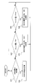
- FIG. 9 is a flow chart showing an example of operation of a master base station in the second embodiment;
- FIG. 10 is a diagram showing an example of a DDDS procedure according to the third embodiment of the present invention
- FIG. FIG. 10 illustrates an example of estimated radio rates based on DDDS reports
- FIG. 14 is a flow chart showing an example of the operation of the master base station in the third embodiment
- FIG. 13 is a diagram showing an example of a DDDS procedure according to the fourth embodiment of the present invention
- FIG. 10 illustrates an example format of a DDDS report including buffer report bits
- FIG. 14 is a flow chart showing an example of the operation of a secondary base station in the fourth embodiment
- FIG. FIG. 14 is a flow chart showing an example of the operation of the master base station in the fourth embodiment
- FIG. 13 is a diagram showing an example of a DDDS procedure according to the fifth embodiment of the present invention
- FIG. 10 is a diagram showing an example of a DDDS report format capable of multiplexing multiple bearers
- FIG. 14 is a flow chart showing an example of the operation of a secondary base station in the fifth embodiment
- FIG. 13 is a diagram showing an example of a DDDS procedure according to the sixth embodiment of the present invention
- FIG. FIG. 22 is a flow chart showing an example of the operation of the master base station in the sixth embodiment
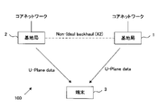
- FIG. 1 shows an example of a wireless communication system according to an embodiment of the present invention.
- a wireless communication system 100 according to an embodiment of the present invention provides dual connectivity. Dual connectivity transmits packet data between one terminal device (eg, UE) and two base stations.
- one terminal device eg, UE
- the base station 1 is a gNB in this embodiment and operates as a master base station.
- the base station 2 is an eNB in this embodiment and operates as a secondary base station.
- Base station 1 and base station 2 are connected via a Non-Ideal backhaul (eg, X2) interface.
- the user terminal 3 is a UE (User Equipment) in this embodiment. User terminal 3 can then communicate with base station 1 and base station 2 . Also, the user terminal 3 can receive downlink data from both the base station 1 and the base station 2 at the same time.
- FIG. 2 shows a configuration example of the radio protocol of the base station.
- a split bearer architecture provides dual connectivity.
- the base stations 1 and 2 include a PDCP (Packet Data Convergence Protocol) layer, an RLC (Radio Link Control) layer, and a MAC (Medium Access Control) layer.
- the base station 2 operating as a secondary base station comprises an LTE (Long Term Evolution) RLC layer and an NR (New Radio) RLC layer.
- the PDCP layer of base station 1 and the RLC layer of base station 2 are connected by an X2 (Xn) interface.
- FIG. 3 shows an example of a dual connectivity operation sequence.
- base station 1 operates as a master base station and base station 2 operates as a secondary base station.
- downlink data to be transmitted from the core network to the user terminal 3 is provided to the base station 1 .
- the base station 1 divides user data given from the core network into data 1 and data 2. The base station 1 then transmits data 1 to the base station 2 and transmits data 2 to the user terminal 3 . The base station 2 transfers data 1 received from the base station 1 to the user terminal 3 . As a result, the user terminal 3 receives data 1 and data 2 . That is, dual connectivity is realized.
- Base station 1 and base station 2 control data transmission between base station 1 and base station 2 by executing the DDDS (Downlink Data Delivery Status) procedure. That is, the data packet transmitted from the base station 1 to the base station 2 is given a polling bit (P in FIG. 3).
- the polling bit indicates whether to request a DDDS report indicating the status of data transmission from the base station 2 to the user terminal 3 . Specifically, if the polling bit is '0', base station 2 will not send a DDDS report to base station 1 . If the polling bit is '1', base station 2 sends a DDDS report to base station 1 .
- the base station 1 requests a DDDS report from the base station 2 at predetermined intervals.
- the predetermined cycle is represented by the number of data packets transmitted from base station 1 to base station 2, for example.
- one DDDS report is required for 100 data packets.
- the base station 1 estimates the state of data transmission from the base station 2 to the user terminal 3 based on the DDDS report. For example, the radio conditions between the base station 2 and the user terminal 3, the state of the data buffer in the base station 2, and the like are estimated. Base station 1 then controls data transmission to base station 2 based on the newly estimated state.
- a bearer corresponds to a data packet path in the following description. Therefore, in cases where the base station 1 and the base station 2 accommodate a large number of bearers, the DDDS procedure is frequently performed, consuming the resources of the base station 1 and the base station 2 (especially the base station 1). And, when the resources consumed to perform the DDDS procedure increase, the transmission rate of the user plane may be limited.
- a plurality of bearers may be set with one user terminal. For example, a bearer for transmitting voice data, a bearer for transmitting image data, and a bearer for transmitting HTML data can be simultaneously set for one terminal.
- the wireless communication system provides the function of mitigating the above trade-off.
- FIG. 4(a) shows an example of the base station 1 operating as a master base station.
- the base station 1 includes a data transmission control unit 11 , a DDDS request unit 12 , a DDDS reception unit 13 , a DDDS storage unit 14 and a bearer classification unit 15 .
- the base station 1 may have other functions not shown in FIG. 4(a).
- FIG. 4(a) shows functions related to a master base station for dual connectivity communication.
- the data transmission control unit 11 transmits downlink data given from the core network to the base station 2 and the user terminal 3. At this time, the data transmission control unit 11 controls data transmission to the base station 2 based on the DDDS report received from the base station 2 . Note that the downlink data is stored in a data packet and transmitted.
- the DDDS request unit 12 transmits a report request requesting a DDDS report to the base station 2.
- a report request is realized by a polling bit P attached to each data packet transmitted from base station 1 to base station 2 .
- the DDDS requesting unit 12 sets the polling bit P to "1".
- the DDDS requesting unit 12 sets the polling bit P to "0". That is, the report request is realized by setting the polling bit P to "1".
- the DDDS requesting unit 12 requests the base station 2 to send a DDDS report, for example, at predetermined intervals. However, the DDDS requesting unit 12 can change the cycle of requesting the DDDS report.
- the DDDS receiving unit 13 receives the DDDS report transmitted from the base station 2.
- the DDDS report received by the DDDS receiver 13 is stored in the DDDS storage 14 . Note that the bearer classification unit 15 will be described later.
- the data transmission control unit 11, the DDDS request unit 12, the DDDS reception unit 13, and the bearer classification unit 15 are realized, for example, by a processor that executes software programs. That is, the functions of the data transmission control unit 11, the DDDS request unit 12, the DDDS reception unit 13, and the bearer classification unit 15 are provided by the processor executing the software program. However, part of the functions of the data transmission control unit 11, the DDDS request unit 12, the DDDS reception unit 13, and the bearer classification unit 15 may be realized by hardware circuits. Also, the DDDS storage unit 14 is realized by, for example, a semiconductor memory.
- FIG. 4(b) shows an example of the base station 2 operating as a secondary base station.
- the base station 2 includes a packet buffer 21 , a packet transfer section 22 , a DDDS creation section 23 and a DDDS transmission section 24 .
- the base station 2 may have other functions not shown in FIG. 4(b).
- FIG.4(b) has shown the function regarding the secondary base station of dual connectivity communication.
- the packet buffer 21 is, for example, a FIFO memory, and stores data packets received from the base station 1.
- the packet transfer unit 22 transmits data packets stored in the packet buffer 21 to the user terminal 3 .
- the polling bit P added to each received packet is guided to the DDDS generator 23 .
- the DDDS creation unit 23 creates a DDDS report when the base station 2 receives the DDDS request.
- the DDDS transmission unit 24 then transmits the DDDS report to the base station 1 .
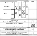
- the format of the DDDS report is as shown in FIG. This format is defined in 3GPP TS38.425.
- the packet transfer unit 22, the DDDS creation unit 23, and the DDDS transmission unit 24 are implemented, for example, by a processor that executes software programs. That is, the functions of the packet transfer unit 22, the DDDS creation unit 23, and the DDDS transmission unit 24 are provided by the processor executing the software program. However, part of the functions of the packet transfer unit 22, the DDDS creation unit 23, and the DDDS transmission unit 24 may be realized by hardware circuits. Also, the packet buffer 21 is realized by, for example, a semiconductor memory.
- Base station 1 operating as a master device transmits a DDDS request to base station 2 operating as a secondary base station, as described above.
- Base station 2 then creates a DDDS report and transmits it to base station 1, and base station 1 receives the DDDS report.
- the received DDDS report is stored in the DDDS storage unit 14 .
- a DDDS report is created for each bearer in base station 2 and stored for each bearer in base station 1 .
- FIG. 6 shows an example of a DDDS procedure according to the first embodiment of the present invention.
- the ⁇ mark shown in FIG. 6 represents the DDDS report stored in the DDDS storage unit 14 .
- the base station 1 executes flow control for five bearers at each processing timing.
- the data transmission control unit 11 performs flow control on bearers 1 to 5, respectively.
- the data transmission control unit 11 reads the DDDS reports of the bearers 1 to 5 from the DDDS storage unit 14 and performs flow control based on each DDDS report.
- 4 DDDS reports are stored for bearer 1 .
- the data transmission control unit 11 performs flow control on the bearer 1 based on the four DDDS reports.
- the number of DDDS reports that the data transmission control unit 11 can execute for each bearer in one control cycle is limited. In this embodiment, the number of DDDS reports that the data transmission control unit 11 can execute for each bearer is five.
- the data transmission control unit 11 performs flow control on the bearers 6 to 10, respectively. However, 7 DDDS reports are stored for bearer 8. In this case, the data transmission control unit 11 executes flow control for the bearer 8 based on the five DDDS reports. That is, two DDDS reports are not read from the DDDS storage unit 14 .
- the data transmission control unit 11 performs flow control on the bearers 11 to 15, respectively.
- the DDDS storage unit 14 still has the DDDS report of the bearer 8 that was not read at time N+1.
- the DDDS reports remaining in the DDDS storage unit 14 are then executed at the next processing timing for the bearers 6-10. That is, the processing associated with the DDDS procedure is distributed in the time domain.
- the number of DDDS reports read from the DDDS storage unit 14 for flow control is limited, so the processor resource consumed for executing the DDDS procedure in the base station 1 is Suppressed. That is, sufficient processor resources are allocated for user plane processing. Therefore, user throughput is improved.
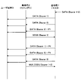
- FIG. 7 shows an example of a DDDS procedure according to the second embodiment of the invention. Direct data transmission from the base station 1 to the user terminal 3 is omitted in FIG. Also, in the following description of the embodiments, the direct data transmission from the base station 1 to the user terminal 3 may be similarly omitted.
- the base station 1 transmits data packets to the base station 2.
- a sequence number SN and a polling bit P are assigned to each data packet.
- a sequence number SN identifies each data packet. Therefore, the base station 2 can detect packet loss using the sequence number SN.
- a data packet whose sequence number SN is "i" may be referred to as "packet SNi”.
- the polling bit P indicates whether to request a DDDS report, as described above. Specifically, if the polling bit is '0', base station 2 will not send a DDDS report to base station 1 . If the polling bit is '1', base station 2 sends a DDDS report to base station 1 .
- the polling bit P is set to "1" at a predetermined cycle.
- the base station 2 transfers the data packet received from the base station 1 to the user terminal 3. For example, upon receiving packets SN0 to SN99, the base station 2 transfers packets SN0 to SN99 to the user terminal 3.
- FIG. 1 For example, upon receiving packets SN0 to SN99, the base station 2 transfers packets SN0 to SN99 to the user terminal 3.
- the DDDS report contains the information shown in Figure 5.
- the base station 1 transmits packets SN100 to SN199 to the base station 2.
- the base station 2 transfers all packets SN100 to SN199 to the user terminal 3.
- FIG. In this case, the sequence number SN of the data packet last transferred from the base station 2 to the user terminal 3 is "199". Therefore, "SN 199" is reported to base station 1 in the DDDS report.
- the base station 1 calculates the difference ⁇ SN between the sequence number SN reported in the new DDDS report and the sequence number SN reported in the previous DDDS report.
- the difference ⁇ SN is 100.
- the base station 1 transmits packets SN200 to SN299 to the base station 2.
- the base station 2 transfers all packets SN200 to SN299 to the user terminal 3.
- FIG. In this case, the sequence number SN of the data packet last transferred from the base station 2 to the user terminal 3 is "299". Therefore, "SN 299" is reported to base station 1 in the DDDS report.
- the base station 1 calculates the difference ⁇ SN.
- the difference ⁇ SN is 100. Further, the base station 1 calculates changes in the difference ⁇ SN.
- the previous difference ⁇ SN and the new difference ⁇ SN match.
- the base station 1 estimates that the radio environment between the base station 2 and the user terminal 3 is stable.
- the base station 1 can accurately estimate the state of data transmission between the base station 2 and the user terminal 3 . If the state of data transmission between the base station 2 and the user terminal 3 can be accurately estimated, appropriate flow control is possible. Therefore, when the previous difference ⁇ SN and the new difference ⁇ SN match, the base station 1 lengthens the period of requesting the DDDS report. That is, the base station 1 lengthens the period of transmitting the DDDS request.
- the transmission cycle of the DDDS request is lengthened when the value of the difference ⁇ SN is the same two times in succession, but the second embodiment is not limited to this method. That is, the transmission period of the DDDS request may be lengthened when the value of the difference ⁇ SN is the same for a predetermined number of times. Also, in the above-described embodiment, the transmission cycle of the DDDS request is lengthened when the change in the difference ⁇ SN is zero, but the second embodiment is not limited to this method. That is, the transmission cycle of the DDDS request may be lengthened when the change in the difference ⁇ SN is smaller than the predetermined threshold.
- the base station 1 when the radio environment between the base station 2 and the user terminal 3 is stable, the base station 1 lengthens the period of requesting DDDS reports. This reduces the frequency with which the base station 1 receives the DDDS report and the frequency with which the DDDS procedure based on the DDDS report is performed. Therefore, processor resources consumed for executing the DDDS procedure in the base station 1 are suppressed. That is, sufficient processor resources are allocated for user plane processing, and data throughput is improved.
- FIG. 8 is a flow chart showing an example of the operation of the master base station (base station 1) in the second embodiment. It should be noted that processing for transmitting downlink data is omitted in FIG.
- the DDDS request unit 12 transmits a DDDS request to the base station 2.
- DDDS requests are implemented by polling bits. Also, the DDDS request is transmitted at a predetermined cycle.
- the DDDS receiving unit 13 receives the DDDS report.
- the DDDS requester 12 extracts the delivery SN from the DDDS report.
- the delivery SN here represents the sequence number identifying the data packet last transferred by the base station 2 to the user terminal 3 .
- the DDDS request unit 12 calculates the difference ⁇ SN.
- the difference ⁇ SN represents the difference between the newly extracted delivery SN and the previous delivery SN.
- the DDDS request unit 12 determines whether or not the difference ⁇ SN is smaller than the threshold for a predetermined number of consecutive times. When the result of this determination is "No", the processing of the base station 1 returns to S1. In this case, the period in which the base station 1 transmits the DDDS request does not change. On the other hand, when the difference ⁇ SN is smaller than the threshold for the predetermined number of times consecutively, the DDDS request unit 12 lengthens the transmission cycle of the DDDS request in S6. After that, the processing of the base station 1 returns to S1. In this case, the base station 1 will transmit the DDDS request at a cycle longer than the initial value.
- FIG. 9 shows an example of a DDDS procedure according to the third embodiment of the invention.
- three bearers are configured. These bearers may be connections that transmit downlink data to the same user terminal or connections that transmit downlink data to different user terminals.
- the base station 1 transmits the data packet of the bearer 1 to the base station 2. At this time, the base station 1 transmits a DDDS request to the base station 2 at a predetermined cycle C1. Base station 2 then transmits a DDDS report for bearer 1 to base station 1 in response to the DDDS request. Similarly, base station 1 sends a DDDS request for bearer 2 to base station 2 at a predetermined period C2, and base station 2 sends a DDDS report for bearer 2 to base station 1.
- FIG. Base station 1 also transmits a DDDS request for bearer 3 to base station 2 at a predetermined period C3, and base station 2 transmits a DDDS report for bearer 3 to base station 1.
- the cycles C1 to C3 may or may not be the same as each other.
- the base station 1 estimates the radio rate between the base station 2 and the corresponding user terminal for each bearer. Note that the method of estimating the radio rate from the DDDS report shown in FIG. 5 is a known technique, so the explanation is omitted. After this, the base station 1 estimates the radio rate of each bearer each time it receives a DDDS report. The base station 1 then monitors changes in the radio rate of each bearer.
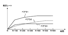
- FIG. 10 shows an example of radio rates estimated based on DDDS reports.
- the estimated radio rate for bearer 1 is approximately constant after time N+400.
- the estimated radio rate of bearer 2 is almost constant after time N+500.
- the estimated radio rate of bearer 3 is almost constant after time N+200.
- the ratio of the radio band allocated to each bearer becomes almost constant. That is, when the radio conditions between the base station 2 and the user terminals are stabilized, the radio rate of each bearer becomes substantially constant. In other words, it is estimated that the radio conditions between the base station 2 and the user terminal are stable when fluctuations in the radio rate of each bearer are smaller than a predetermined threshold.
- the base station 1 lengthens the transmission cycle of the DDDS request when the variation in the radio rate of each bearer becomes smaller than a predetermined threshold. For example, after time N+500, the estimated radio rates of bearers 1 to 3 are substantially constant. In this case, the base station 1 sets the transmission cycle of the DDDS requests for the bearers 1 to 3 longer than C1 to C3, respectively.
- the base station 1 may change the transmission cycle of the DDDS request for each bearer.
- the transmission period of the DDDS request for bearer 1 is set to be longer than C1 at time N+400
- the transmission period of the DDDS request for bearer 2 is set to be longer than C2 at time N+500
- the DDDS request for bearer 3 is set to be longer than C2 at time N+500.
- the request transmission period may be set to be longer than C3 at time N+200.
- the base station 1 when the radio environment between the base station 2 and the user terminal 3 stabilizes, the base station 1 lengthens the DDDS report request period. Therefore, in the third embodiment, similarly to the second embodiment, processor resources consumed for executing the DDDS procedure in the base station 1 are suppressed.
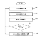
- FIG. 11 is a flow chart showing an example of the operation of the master base station (base station 1) in the third embodiment. In addition, in FIG. 11, the process of transmitting downlink data is omitted.
- S11-S12 are substantially the same as S1-S2 shown in FIG. That is, the DDDS request unit 12 transmits a DDDS request to the base station 2 at predetermined intervals for each bearer. Then, the DDDS receiver 13 receives the DDDS report.
- the base station 1 estimates the radio rate between the base station 2 and the user terminal based on the DDDS report for each bearer. In S14, the base station 1 determines whether or not the radio rate is constant.
- Constant includes a state in which the variation in radio rate is less than a predetermined threshold.
- the processing of the base station 1 returns to S11. In this case, the period in which the base station 1 transmits the DDDS request does not change.
- the DDDS request unit 12 lengthens the transmission cycle of the DDDS request in S15. After that, the processing of the base station 1 returns to S11. In this case, the base station 1 will transmit the DDDS request at a cycle longer than the initial value.
- FIG. 12 shows an example of a DDDS procedure according to the fourth embodiment of the invention. Also in the fourth embodiment, the base station 1 transmits a DDDS request to the base station 2 at predetermined intervals. Base station 2 transmits a DDDS report to base station 1 in response to the DDDS request. The base station 1 then performs flow control based on the DDDS report.
- the DDDS creation unit 23 constantly monitors the amount of data packets stored in the packet buffer 21 (hereinafter referred to as buffer amount). Then, when the buffer amount exceeds a predetermined threshold TH1, the DDDS creation unit 23 autonomously creates a DDDS report and transmits it to the base station 1. FIG. That is, in this case, even when no DDDS request is received from base station 1, a DDDS report is generated autonomously. This DDDS report is used to report to the base station 1 that the buffer amount has exceeded the threshold.
- reporting that the buffer amount has exceeded the threshold is realized by setting "1" to the "buffer report bit (Buffer Report)" shown in FIG.
- the buffer report bit is set using an unused area in the format shown in FIG.
- the base station 1 When the base station 1 recognizes that the buffer amount of the base station 2 has exceeded the threshold, it stops transmitting data to the base station 2. In this case, the base station 1 transmits data packets only to the user terminal 3 .
- the base station 2 continues data transfer to the user terminal 3. Therefore, when the data transmission from the base station 1 to the base station 2 stops, the buffer amount decreases. Then, when the buffer amount becomes less than a predetermined threshold TH2, the DDDS creation unit 23 autonomously creates a DDDS report and transmits it to the base station 1.
- FIG. This DDDS report is used to report to the base station 1 that the buffer amount is below the threshold. Also, this reporting is realized by setting the buffer report bit described above to "0".
- the threshold TH1 and the threshold TH2 may be the same, or the threshold TH2 may be smaller than the threshold TH1.
- FIG. 14 is a flow chart showing an example of the operation of the secondary base station (base station 2) in the fourth embodiment. Note that FIG. 14 depicts only the steps involved in the process of transmitting the DDDS report.
- the base station 2 checks whether it has received a DDDS request from the base station 1. Then, if the DDDS request has been received, the DDDS creating unit 23 creates the DDDS report shown in FIG.
- the DDDS creating unit 23 monitors the buffer amount in S23-S24. Then, when the buffer amount exceeds the threshold TH1, in S25, the DDDS creating unit 23 creates the DDDS report shown in FIG. At this time, "1 (NG)" is set in the buffer report bit. The DDDS transmission unit 24 then transmits this DDDS report to the base station 1 . On the other hand, when the buffer amount becomes smaller than the threshold TH2, the DDDS creating unit 23 creates the DDDS report shown in FIG. 13 in S26. At this time, "0 (OK)" is set in the buffer report bit. The DDDS transmission unit 24 then transmits this DDDS report to the base station 1 .
- FIG. 15 is a flow chart showing an example of the operation of the master base station (base station 1) in the fourth embodiment. Note that the process of transmitting the DDDS request is omitted in FIG.
- the DDDS receiving unit 13 waits for a DDDS report transmitted from the base station 2. Note that while the base station 1 is transmitting data packets to the base station 2, the DDDS request is transmitted to the base station 2 at a predetermined cycle, so the base station 1 receives the DDDS report periodically. Become.
- the base station 1 determines that the data transmission control unit 11 has transmitted a data packet to the base station 2 and the buffer report bit of the DDDS report is "NG (buffer Amount > Threshold)” is determined. Then, when the above two conditions are satisfied, the data transmission control unit 11 stops data transmission to the base station 2 in S33. Note that the data transmission control unit 11 may continue data transmission to the user terminal 3 .
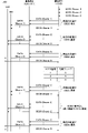
- FIG. 16 shows an example of a DDDS procedure according to the fifth embodiment of the invention.
- multiple bearers (1-3) are set. That is, the base station 1 transmits data packets to the base station 2 for each bearer. Also, the base station 1 transmits a DDDS request to the base station 2 at predetermined intervals for each bearer. Note that the DDDS request is indicated as "P1" in FIG.
- base station 2 when base station 1 transmits a DDDS request for bearer 3, base station 2 creates a DDDS report corresponding to bearer 3 and transmits it to base station 1. At this time, the base station 2 transmits, for example, a DDDS report in the format shown in FIG.
- the timing of transmitting DDDS requests to each bearer is not synchronized with each other, so DDDS requests may be transmitted to multiple bearers within a short period of time. That is, the base station 2 may receive DDDS requests for multiple bearers within a short period of time. In this case, base station 2 transmits a DDDS report in which multiple bearers are multiplexed to base station 1 .
- base station 1 transmits a DDDS request for bearer 1 and a DDDS request for bearer 2 to base station 2 almost simultaneously.
- base station 2 receives the DDDS request for bearer 1 and the DDDS request for bearer 2 at approximately the same time.
- Base station 2 then creates a DDDS report (MUX_DDDS) in which bearer 1 and bearer 2 are multiplexed and transmits it to base station 1 .
- MUX_DDDS DDDS report
- FIG. 17 shows an example of a DDDS report format capable of multiplexing multiple bearers.
- the number of multiplexed bearers represents the number of bearers multiplexed in one DDDS report. For example, in the case shown in FIG. 16, bearer 1 and bearer 2 are multiplexed, so the number of multiplexed bearers N is two.
- the bearer number identifies the bearer to be multiplexed.
- the DDDS-related information corresponds to, for example, the information shown in FIG. Note that this format can be added as, for example, PDU Type 3 in TS38.425 of 3GPP.
- the format shown in FIG. 17 is used when multiplexing multiple bearers, it may also be used when transmitting a DDDS report for one bearer.
- the multiple bearer number N is one.
- FIG. 18 is a flow chart showing an example of the operation of the secondary base station (base station 2) in the fifth embodiment. Note that FIG. 18 depicts only the steps involved in the process of sending the DDDS report.
- the base station 2 waits for a DDDS request transmitted from the base station 1.
- the DDDS report creation unit 23 creates a DDDS report in response to the DDDS request.
- the DDDS report creating unit 23 starts a timer. This timer counts the period of waiting for another bearer's DDDS request.
- the base station 2 waits for DDDS requests from other bearers. Then, if the base station 2 receives the DDDS request of another bearer before the timer expires, the DDDS report creation unit 23 creates a DDDS report in S46. At this time, a new DDDS report is added within the format shown in FIG. This realizes bearer multiplexing. Then, when the timer expires, the DDDS transmission unit 24 transmits the DDDS report to the base station 1 in S47.
- the secondary base station of the fifth embodiment can transmit DDDS reports in which multiple bearers are multiplexed. Therefore, the number of times the master base station receives the DDDS reports is reduced, and processor resources consumed for executing the DDDS procedure at the master base station are reduced.
- timer setting time increases the number of bearers multiplexed in one DDDS report, increasing the efficiency of DDDS-related processing.
- timer setting time is too long, delays in flow control tend to occur, and the transmission rate may not be properly controlled. Therefore, it is preferable to appropriately determine the set time of the timer in consideration of these factors.
- FIG. 19 shows an example of a DDDS procedure according to the sixth embodiment of the invention.
- bearers 1-3 are set.
- Bearers 1-3 carry downlink data for different user terminals.
- bearers 1-3 transmit downlink data to user terminals UE1-UE3, respectively.
- the radio quality of each bearer depends on the location of the user terminal. For example, when the user terminal is located near the base station, the radio quality tends to be high, and when the user terminal is located at the edge of the cell, the radio quality tends to be low.
- the base station 1 estimates the radio quality of each bearer. That is, the base station 1 estimates the radio quality between the base station 2 and each user terminal.
- the radio quality of each bearer is estimated by known techniques. For example, the radio quality of each bearer can be estimated based on DDDS reports.
- the base station 1 groups a plurality of bearers based on radio quality. Bearers 1-2 are classified in quality group A and bearer 3 is classified in quality group B in this example. The grouping of bearers is performed by the bearer classification unit 15 shown in FIG. 4(a).
- the states of multiple bearers belonging to the same quality group are estimated to be similar to each other.
- the state of bearer 1 and the state of bearer 2 are estimated to be similar to each other. Therefore, the base station 1 can perform flow control for each quality group. Therefore, the base station 1 selects a representative bearer within each quality group. Then, the base station 1 acquires the DDDS report of the representative bearer and executes flow control of each bearer belonging to the same quality group.
- bearer 1 is selected as the representative bearer in quality group A.
- the base station 1 transmits the DDDS request for the bearer 1 to the base station 2 at a predetermined cycle, but does not transmit the DDDS request for the bearer 2 .
- Base station 2 then transmits the DDDS report for bearer 1 to base station 1 .
- Base station 1 then performs flow control for bearer 1 and bearer 2 based on the DDDS report for bearer 1 . This reduces the processing associated with the DDDS procedure.
- the sixth embodiment is not limited to this method.
- the cycle of transmitting the DDDS requests of the other bearers may be longer than the cycle of transmitting the DDDS requests of the representative bearer.
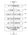
- FIG. 20 is a flow chart showing an example of the operation of the master base station (base station 1) in the sixth embodiment. It should be noted that FIG. 20 shows only the steps related to the DDDS procedure.
- the bearer classification unit 15 estimates the radio quality of each bearer.
- the bearer classification unit 15 groups bearers based on radio quality. That is, bearers are classified into quality groups.
- the bearer classification unit 15 selects a representative bearer for each quality group.
- the DDDS request unit 12 transmits to the base station 2 a DDDS request for the representative bearer.
- the DDDS receiving unit 13 receives the DDDS report of the representative bearer from the base station 2 .
- the data transmission control unit 11 executes flow control of each bearer within the quality group based on the DDDS report of the representative bearer.
- processing for DDDS is distributed (or averaged) in the time domain.
- DDDS multiplexing also reduces the number of DDDS reports per unit time.
- processing related to DDDS is reduced by performing flow control in units of radio quality.
- the user plane load corresponds to 80% of the CPU resources and the DDDS processing load corresponds to 80% of the CPU resources when distributed processing is not performed.
- CPU resources allocated to the user plane are insufficient, resulting in low data throughput.
- the peak DDDS processing load can be reduced to, for example, 20 percent of the CPU resources. Then, sufficient CPU resources can be allocated to the user plane, and data throughput is improved.
- the PPS per 1000 milliseconds is about 417000 packets.
- the PPS required for DDDS is approximately 200 packets. That is, the processing load associated with DDDS is small.
- the wireless communication system accommodates 1000 bearers, the PPS required for DDDS is about 200000 packets. That is, the processing load related to DDDS corresponds to approximately 50% of the user plane load.
- multiplexing 10 bearers in one DDDS report reduces the processing load associated with DDDS to about 5% of the user plane load.
- Base station (master base station) 2 Base station (secondary base station) 3 User terminal 11 Data transmission control unit 12 DDDS request unit 13 DDDS reception unit 14 DDDS storage unit 15 Bearer classification unit 21 Packet buffer 22 Packet transfer unit 23 DDDS creation unit 24 DDDS transmission unit 100 Wireless communication system
Landscapes
- Engineering & Computer Science (AREA)
- Computer Networks & Wireless Communication (AREA)
- Signal Processing (AREA)
- Mobile Radio Communication Systems (AREA)
Priority Applications (4)
| Application Number | Priority Date | Filing Date | Title |
|---|---|---|---|
| JP2023510049A JP7533770B2 (ja) | 2021-03-31 | 2021-03-31 | 基地局装置、無線通信システム、および無線通信方法 |
| PCT/JP2021/013902 WO2022208758A1 (ja) | 2021-03-31 | 2021-03-31 | 基地局装置、無線通信システム、および無線通信方法 |
| CN202180094670.2A CN116998183A (zh) | 2021-03-31 | 2021-03-31 | 基站装置、无线通信系统及无线通信方法 |
| US18/233,930 US20230388857A1 (en) | 2021-03-31 | 2023-08-15 | Base station device, radio communication system, and radio communication method |
Applications Claiming Priority (1)
| Application Number | Priority Date | Filing Date | Title |
|---|---|---|---|
| PCT/JP2021/013902 WO2022208758A1 (ja) | 2021-03-31 | 2021-03-31 | 基地局装置、無線通信システム、および無線通信方法 |
Related Child Applications (1)
| Application Number | Title | Priority Date | Filing Date |
|---|---|---|---|
| US18/233,930 Continuation US20230388857A1 (en) | 2021-03-31 | 2023-08-15 | Base station device, radio communication system, and radio communication method |
Publications (1)
| Publication Number | Publication Date |
|---|---|
| WO2022208758A1 true WO2022208758A1 (ja) | 2022-10-06 |
Family
ID=83458200
Family Applications (1)
| Application Number | Title | Priority Date | Filing Date |
|---|---|---|---|
| PCT/JP2021/013902 Ceased WO2022208758A1 (ja) | 2021-03-31 | 2021-03-31 | 基地局装置、無線通信システム、および無線通信方法 |
Country Status (4)
| Country | Link |
|---|---|
| US (1) | US20230388857A1 (https=) |
| JP (1) | JP7533770B2 (https=) |
| CN (1) | CN116998183A (https=) |
| WO (1) | WO2022208758A1 (https=) |
Citations (2)
| Publication number | Priority date | Publication date | Assignee | Title |
|---|---|---|---|---|
| JP2019036873A (ja) * | 2017-08-17 | 2019-03-07 | 株式会社Nttドコモ | 基地局 |
| WO2021009883A1 (ja) * | 2019-07-17 | 2021-01-21 | 株式会社Nttドコモ | 端末及び通信ノード |
Family Cites Families (6)
| Publication number | Priority date | Publication date | Assignee | Title |
|---|---|---|---|---|
| US9603050B2 (en) * | 2012-02-22 | 2017-03-21 | Telefonaktiebolaget Lm Ericsson (Publ) | Method and base station for controlling wireless communication of data |
| US9497647B2 (en) * | 2012-03-14 | 2016-11-15 | Telefonaktiebolaget Lm Ericsson (Publ) | Methods and devices for reporting in a cellular radio network |
| CA2910662C (en) * | 2013-04-26 | 2017-10-31 | Huawei Technologies Co., Ltd. | Data transmission method, base station, and wireless communications device |
| CN109348508B (zh) * | 2013-11-11 | 2022-04-12 | 华为技术有限公司 | 数据传输方法及装置 |
| CN106031277B (zh) * | 2015-01-29 | 2018-11-30 | 华为技术有限公司 | 无线承载重配置方法、建立方法、用户设备和基站 |
| EP4307588A3 (en) * | 2017-06-20 | 2024-02-28 | Apple Inc. | Devices and methods for flow-control triggering and feedback |
-
2021
- 2021-03-31 CN CN202180094670.2A patent/CN116998183A/zh active Pending
- 2021-03-31 WO PCT/JP2021/013902 patent/WO2022208758A1/ja not_active Ceased
- 2021-03-31 JP JP2023510049A patent/JP7533770B2/ja active Active
-
2023
- 2023-08-15 US US18/233,930 patent/US20230388857A1/en active Pending
Patent Citations (2)
| Publication number | Priority date | Publication date | Assignee | Title |
|---|---|---|---|---|
| JP2019036873A (ja) * | 2017-08-17 | 2019-03-07 | 株式会社Nttドコモ | 基地局 |
| WO2021009883A1 (ja) * | 2019-07-17 | 2021-01-21 | 株式会社Nttドコモ | 端末及び通信ノード |
Non-Patent Citations (1)
| Title |
|---|
| HUAWEI: "Downlink Flow control for EN-DC", 3GPP DRAFT; R3-172456, 3RD GENERATION PARTNERSHIP PROJECT (3GPP), MOBILE COMPETENCE CENTRE ; 650, ROUTE DES LUCIOLES ; F-06921 SOPHIA-ANTIPOLIS CEDEX ; FRANCE, vol. RAN WG3, no. Qingdao, China; 20170627 - 20170629, 26 June 2017 (2017-06-26), Mobile Competence Centre ; 650, route des Lucioles ; F-06921 Sophia-Antipolis Cedex ; France , XP051302397 * |
Also Published As
| Publication number | Publication date |
|---|---|
| US20230388857A1 (en) | 2023-11-30 |
| JP7533770B2 (ja) | 2024-08-14 |
| CN116998183A (zh) | 2023-11-03 |
| JPWO2022208758A1 (https=) | 2022-10-06 |
Similar Documents
| Publication | Publication Date | Title |
|---|---|---|
| US8068476B2 (en) | Method for allocating transmission period in a wireless communication system | |
| US7075911B2 (en) | Method and system for enhanced packet transmission in cellular networks | |
| US10321513B2 (en) | Method for PDCP control PDU transmission by user equipment (UE) | |
| US11297528B2 (en) | Apparatus and method for controlling congestion in wireless communication system | |
| US11843969B2 (en) | Method and device for processing buffer state report in wireless communication system using inter-eNB carrier aggregation technology | |
| RU2490795C2 (ru) | Способ сообщения о запасе мощности | |
| CN105432115B (zh) | 用于双连接的方法和装置 | |
| WO2016163432A1 (ja) | ユーザ端末及び無線通信装置 | |
| KR20180005210A (ko) | 데이터의 전송을 제어하기 위한 방법 | |
| CN105191216A (zh) | 用于多流聚合的缓冲区状态报告的系统和方法 | |
| US10911985B2 (en) | Service data splitting method and apparatus | |
| CN101998615A (zh) | 辅载波小区同步方法及终端 | |
| US12120036B2 (en) | Multi-link device adopting block acknowledgment and packet allocation method thereof | |
| EP4426005A1 (en) | Data offloading method and apparatus, electronic device, and storage medium | |
| US10142253B2 (en) | Method for efficient reliable transmission | |
| JP7533770B2 (ja) | 基地局装置、無線通信システム、および無線通信方法 | |
| KR20200057647A (ko) | 무선 접속 시스템에서의 다중 연결 지원과 데이터 전송 효율 향상을 위한 네트워크 제어 방법 및 장치 | |
| EP4465734A1 (en) | A system and a method for providing connection within a 5g network cell | |
| US11395366B2 (en) | Transmission apparatus, reception apparatus, and method | |
| JP2019176266A (ja) | リソース制御装置、リソース制御方法及びリソース制御プログラム | |
| JP2019176265A (ja) | 端末装置、通知方法及び通知プログラム |
Legal Events
| Date | Code | Title | Description |
|---|---|---|---|
| 121 | Ep: the epo has been informed by wipo that ep was designated in this application |
Ref document number: 21934924 Country of ref document: EP Kind code of ref document: A1 |
|
| WWE | Wipo information: entry into national phase |
Ref document number: 2023510049 Country of ref document: JP |
|
| WWE | Wipo information: entry into national phase |
Ref document number: 202180094670.2 Country of ref document: CN |
|
| NENP | Non-entry into the national phase |
Ref country code: DE |
|
| 122 | Ep: pct application non-entry in european phase |
Ref document number: 21934924 Country of ref document: EP Kind code of ref document: A1 |