WO2022208699A1 - 内燃機関の吸気構造 - Google Patents
内燃機関の吸気構造 Download PDFInfo
- Publication number
- WO2022208699A1 WO2022208699A1 PCT/JP2021/013730 JP2021013730W WO2022208699A1 WO 2022208699 A1 WO2022208699 A1 WO 2022208699A1 JP 2021013730 W JP2021013730 W JP 2021013730W WO 2022208699 A1 WO2022208699 A1 WO 2022208699A1
- Authority
- WO
- WIPO (PCT)
- Prior art keywords
- intake
- tumble
- flow path
- valve
- passage
- Prior art date
- Legal status (The legal status is an assumption and is not a legal conclusion. Google has not performed a legal analysis and makes no representation as to the accuracy of the status listed.)
- Ceased
Links
Images
















Classifications
-
- F—MECHANICAL ENGINEERING; LIGHTING; HEATING; WEAPONS; BLASTING
- F02—COMBUSTION ENGINES; HOT-GAS OR COMBUSTION-PRODUCT ENGINE PLANTS
- F02B—INTERNAL-COMBUSTION PISTON ENGINES; COMBUSTION ENGINES IN GENERAL
- F02B31/00—Modifying induction systems for imparting a rotation to the charge in the cylinder
- F02B31/04—Modifying induction systems for imparting a rotation to the charge in the cylinder by means within the induction channel, e.g. deflectors
-
- F—MECHANICAL ENGINEERING; LIGHTING; HEATING; WEAPONS; BLASTING
- F02—COMBUSTION ENGINES; HOT-GAS OR COMBUSTION-PRODUCT ENGINE PLANTS
- F02B—INTERNAL-COMBUSTION PISTON ENGINES; COMBUSTION ENGINES IN GENERAL
- F02B31/00—Modifying induction systems for imparting a rotation to the charge in the cylinder
- F02B31/04—Modifying induction systems for imparting a rotation to the charge in the cylinder by means within the induction channel, e.g. deflectors
- F02B31/06—Movable means, e.g. butterfly valves
-
- F—MECHANICAL ENGINEERING; LIGHTING; HEATING; WEAPONS; BLASTING
- F02—COMBUSTION ENGINES; HOT-GAS OR COMBUSTION-PRODUCT ENGINE PLANTS
- F02D—CONTROLLING COMBUSTION ENGINES
- F02D9/00—Controlling engines by throttling air or fuel-and-air induction conduits or exhaust conduits
- F02D9/08—Throttle valves specially adapted therefor; Arrangements of such valves in conduits
- F02D9/10—Throttle valves specially adapted therefor; Arrangements of such valves in conduits having pivotally-mounted flaps
-
- Y—GENERAL TAGGING OF NEW TECHNOLOGICAL DEVELOPMENTS; GENERAL TAGGING OF CROSS-SECTIONAL TECHNOLOGIES SPANNING OVER SEVERAL SECTIONS OF THE IPC; TECHNICAL SUBJECTS COVERED BY FORMER USPC CROSS-REFERENCE ART COLLECTIONS [XRACs] AND DIGESTS
- Y02—TECHNOLOGIES OR APPLICATIONS FOR MITIGATION OR ADAPTATION AGAINST CLIMATE CHANGE
- Y02T—CLIMATE CHANGE MITIGATION TECHNOLOGIES RELATED TO TRANSPORTATION
- Y02T10/00—Road transport of goods or passengers
- Y02T10/10—Internal combustion engine [ICE] based vehicles
- Y02T10/12—Improving ICE efficiencies
Definitions
- the present invention relates to an intake structure for an internal combustion engine in which an intake passage is divided into a main flow passage and a tumble flow passage.
- Patent Document 1 discloses a structure in which an intake passage of an internal combustion engine is vertically divided into a main flow passage and a tumble flow passage to generate a tumble flow.
- only one variable intake flow rate valve throttle valve in Patent Document 1 for changing the flow rate of intake air passing through the intake passage is provided in the intake passage.
- the variable intake flow rate valve is opened until the intake passage is nearly fully opened, the fast-flowing intake air passing through the tumble flow passage on the lower side of the partition and the intake air passing through the main flow passage on the upper side of the partition are It is conceivable that the intake air may collide downstream of the partition and the intake air passing through the main flow path may not be efficiently introduced into the combustion chamber. Further, if a tumble valve for closing the tumble flow path side is provided in addition to the variable intake flow rate valve, there is a problem that the number of parts increases and the cost rises.
- the present invention has been made in view of the above problems, and includes an intake passage communicating with a combustion chamber of an internal combustion engine; a single intake air flow rate variable valve provided in the intake passage for changing the opening area of the intake passage to change the flow rate of the intake air flowing through the intake passage; a partitioning portion downstream of the variable intake air flow rate valve that divides the intake passage into a tumble flow passage configured such that intake air generates a tumble flow in the combustion chamber and a main flow passage excluding the tumble flow passage;
- the intake flow rate variable valve has a tumble flow path side closing valve portion that closes only the tumble flow path side, The opening of the tumble flow path side of the tumble flow path side closing valve portion is made smaller as the opening of the main flow path is increased.
- the amount of intake air flowing through the tumble flow path can be decreased. It is possible to suppress the reduction of the amount of intake air introduced into the combustion chamber due to the interference of the flow of air, and there is no need to provide a tumble valve that closes the tumble flow path side separately from the intake flow rate variable valve, and the number of parts is reduced. It is possible to prevent the increase and suppress the cost increase.
- variable intake flow rate valve when the variable intake flow rate valve is fully open with respect to the main flow path, the opening on the tumble flow path side can be fully closed.
- the intake air flowing through the main passage is more smoothly supplied to the combustion chamber.
- the intake air flow rate variable valve enlarges the opening on the main flow path side.
- the amount of intake air flowing through the main flow path is increased and the amount of intake air flowing through the tumble flow path is decreased, so that the influence of the intake air passing through the tumble flow path on the intake air passing through the main flow path. can be gradually reduced.
- variable intake flow rate valve includes a butterfly valve portion that closes the intake passage; and a tumble flow path side closing valve portion that closes only the tumble flow path.
- the tumble flow path can be closed appropriately by the tumble flow path side closing valve portion.
- the tumble flow path side closing valve portion is fixed in a direction perpendicular to the butterfly valve portion.
- the opening of the tumble flow path can be made smaller by the tumble flow path side closing valve section as the opening degree of the butterfly valve portion increases in the direction in which it becomes horizontal with respect to the intake passage.
- the tumble flow path side closing valve portion may be separated from the upstream end of the partition portion.
- the tumble flow path closing valve does not hinder the reverse flow effect when the variable intake flow rate valve is gradually opened.
- the intake flow rate variable valve has a through hole,
- the variable intake flow rate valve can be slid in a direction that intersects the flow direction of the intake air, thereby making it possible to vary the opening ratio with respect to the intake passage.
- the position of the intake air flowing downstream can be adjusted according to the position of the through hole, so that the intake air can flow to a desired position in a direction intersecting the flow direction of the intake air.
- the main flow path may be closed while the through hole is opened from the tumble flow path side.
- the intake air when the opening degree of the tumble valve is low, the intake air can flow only through the tumble flow path, and the tumble flow path can be strengthened.
- the main flow path may be formed to have a larger cross-sectional area than the tumble flow path, and the through-hole may have an opening width corresponding to the upstream opening of the main flow path.
- the amount of intake air flowing through the tumble flow path can be decreased.
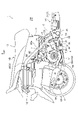
- FIG. 1 is a right side view of a motorcycle equipped with a power unit having an intake structure for an internal combustion engine according to Embodiment 1 of the present invention. It is the rear right side of the motorcycle of FIG. 1 with the body cover removed.
- FIG. 3 is a side cross-sectional view of a power unit taken out from FIG. 2 and shown in substantially the same orientation as shown in FIG. 2 and having an intake structure for an internal combustion engine according to Embodiment 1;
- FIG. 4 is an enlarged view of a main portion of FIG. 3;
- FIG. 3 is a perspective view of the vicinity of the throttle valve cut in a direction perpendicular to the throttle valve shaft and the partition. It is the front view which looked at the throttle body from the upstream side opening.
- FIG. 3 is a side cross-sectional view of a power unit taken out from FIG. 2 and shown in substantially the same orientation as shown in FIG. 2 and having an intake structure for an internal combustion engine according to Embodiment 1;
- FIG. 4 is an enlarged view
- FIG. 4 is a cross-sectional view of the vicinity of the throttle valve when the throttle valve is in a fully closed state;
- FIG. 8 is a diagram showing the flow of intake air in FIG. 7;
- FIG. 8 is a diagram showing a gradually opened state of the throttle valve of FIG. 7;
- FIG. 10 is a diagram showing the flow of intake air in FIG. 9;
- FIG. 8 is a diagram showing a low opening state of the throttle valve of FIG. 7;
- FIG. 12 is a diagram showing the flow of intake air in FIG. 11;
- FIG. 8 is a diagram showing a middle opening state of the throttle valve of FIG. 7;
- FIG. 14 is a diagram showing the flow of intake air in FIG. 13;
- FIG. 13 is a diagram showing the flow of intake air in FIG. 13;
- FIG. 4 is a cross-sectional view of the vicinity of the throttle valve in a state in which the butterfly valve portion of the throttle valve is in a fully open state and the tumble passage side blocking valve portion is in a closed state;
- FIG. 16 is a diagram showing the flow of intake air in FIG. 15;
- FIG. 2 is a cross-sectional view of a main part of an internal combustion engine to which the intake structure for an internal combustion engine of the second embodiment is applied;
- FIG. 18 is a schematic diagram of a state when a throttle valve is fully closed in the intake structure of FIG. 17;
- FIG. 18B is a diagram showing a state of the throttle valve of FIG. 18A at a low opening degree;
- FIG. 18B is a diagram showing a state of the throttle valve of FIG.
- FIG. 18A is a middle opening
- FIG. 18B is a diagram showing the state of the throttle valve of FIG. 18A when it is fully open
- FIG. 18B is a view showing a state in which the upper surface of the through hole of the throttle valve of FIG. 18A is positioned at the lower edge of the partition
- FIG. 18B is a view showing a state in which the upper surface of the through hole of the throttle valve of FIG. 18A is positioned at the upper edge of the partition
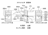
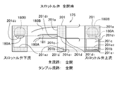
- FIG. 11 is a schematic cross-sectional view of the first modification of the intake structure of the internal combustion engine of the second embodiment, with the throttle valve fully closed
- FIG. 20B is a diagram showing a state of the throttle valve of FIG. 20A at a low opening degree
- FIG. 20B is a diagram showing a state of the throttle valve of FIG. 20A at a low opening degree
- FIG. 20B is a diagram showing a state of the throttle valve of FIG. 20A at a middle opening;
- FIG. 20B is a diagram showing the state of the throttle valve of FIG. 20A when it is fully open;
- FIG. 20B is a diagram showing a step in the intake passage when the throttle valve of FIG. 20A is fully open;
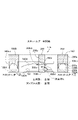
- FIG. 11 is a schematic cross-sectional view of a second modified example of the intake structure of the internal combustion engine of the second embodiment when the throttle valve is fully closed;
- FIG. 22B is a diagram showing a low opening state of the throttle valve of FIG. 22A;
- FIG. 22B is a diagram showing a middle opening state of the throttle valve of FIG. 22A;
- FIG. 22B is a view showing a fully open state of the throttle valve of FIG.
- FIG. 22A is a diagram showing a step in the intake passage when the throttle valve is gradually opened in FIG. 22A;
- FIG. 22B is a diagram showing a step of the intake passage in the intermediate opening state of the throttle valve of FIG. 22A;
- FIG. 22B is a diagram showing a step of the intake passage when the throttle valve of FIG. 22A is fully opened;
- FIG. 11 is a schematic cross-sectional view of a state in which the throttle valve is gradually opened in the third modification of the intake structure of the internal combustion engine of the second embodiment;
- FIG. 11 is a schematic cross-sectional view of a state when the throttle valve is fully open in the fourth modification of the intake structure for the internal combustion engine of the second embodiment;
- FIG. 12 is a schematic cross-sectional view of a state when the throttle valve is fully open in the fifth modification of the intake structure for the internal combustion engine of the second embodiment;
- FIG. 1 An intake structure for an internal combustion engine according to a first embodiment of the present invention will be described with reference to FIGS. 1 to 16.
- FIG. It should be noted that directions such as front, rear, left, right, up and down in the description of this specification and the scope of claims follow the direction of the vehicle when the power unit having the intake structure for the internal combustion engine according to the present embodiment is mounted in the vehicle. do.
- the vehicle is a small vehicle, specifically a motorcycle.
- the intake passage 70 and the intake passage 80 of the throttle body 7 the upper side of the partition 81 that divides them along the intake flow direction F is described as the "upper" side, and the lower side is described as the "lower” side.
- an arrow FR indicates the front of the vehicle, LH the left of the vehicle, RH the right of the vehicle, and UP the upper of the vehicle.
- FIG. 18 to 26 An intake structure for an internal combustion engine according to 26.
- FIG. 1 shows the right side of a motorcycle 1 equipped with a power unit 3 of Example 1 having an intake structure for an internal combustion engine of the first embodiment of the present invention.
- 2 shows the rear right side of the motorcycle 1 of FIG. 1 with the body cover 10 removed. 1 and 2 will also be referred to in the second embodiment, which will be described later.
- a motorcycle 1 according to the first embodiment is a so-called scooter-type motorcycle, and has a vehicle body front portion 1A and a vehicle body rear portion 1B connected via a low floor portion 1C, and a vehicle body frame 2 forming the skeleton of the vehicle body.
- generally consists of a down tube 21 and a main pipe 22 (see FIG. 2). That is, a down tube 21 extends downward from a head pipe 20 in the front portion 1A of the vehicle body, and the down tube 21 bends horizontally at its lower end to extend rearward under the floor portion 1C, and as shown in FIG.
- a pair of left and right main pipes 22 are connected via a connecting frame 23 arranged in the width direction of the vehicle. It bends and extends backward.
- a storage box 11 and a fuel tank 12 are supported above the inclined portion 22a of the main pipe 22, and the storage box 11 and the fuel tank 12 are closed by an occupant seat 13 mounted thereabove.
- a vehicle body cover 10 covers the lower part of the passenger seat 13 including the fuel tank 12 .
- a handlebar 14 is provided upwardly while being pivotally supported by a head pipe 20, and a front fork 15 extends downward, and a front wheel 16 is pivotally supported at the lower end thereof.
- a bracket 24 is protruded near the lower end of the inclined portion 22a of the main pipe 22, and the power unit is connected to the bracket 24 via a link member 25. 3 is connected and supported so as to be able to swing.
- the front portion of the power unit 3 is a single-cylinder four-stroke cycle air-cooled internal combustion engine (hereinafter simply referred to as the "internal combustion engine") 30, and a crankshaft is mounted in the front portion of the power unit case 50 constituting the crankcase portion 50a.
- the hanger arm 52 protruding forward from the lower end of the power unit case 50 is in a posture in which the cylinder axis C is greatly inclined forward to a substantially horizontal state. are connected via a link member 25 attached to a bracket 24 of the main pipe 22 so as to be vertically swingable.
- a cylinder block 31, a cylinder head 32, and a cylinder head cover 33, which constitute the internal combustion engine 30, are stacked in order on the front portion of the power unit case 50, which constitutes the crankcase portion 50a.
- a power transmission case portion 55 equipped with a belt-type continuously variable transmission and the like extends integrally from the crankcase portion 50a to the rear left side, and a rear axle 56, which is the output shaft of the power unit 3, is provided at its rear portion. and the rear wheels 17 are attached. That is, the power unit 3 is a so-called swing unit, and a rear cushion (not shown) is interposed between the power transmission case portion 55 at the rear of the power unit 3 and the rear of the main pipe 22 .
- the inlet pipe 6 extends from the upper portion of the cylinder head 32 of the internal combustion engine 30, which tilts forward greatly, and curves rearward. is located above the cylinder block 31 , and an air cleaner device 86 connected to the throttle body 7 via a connecting tube 85 is arranged above the power transmission case portion 55 .
- an exhaust pipe 38 extending downward from the lower portion of the cylinder head 32 is bent rearward and extends rearward while biased to the right side, and is connected to a muffler 39 on the right side of the rear wheel 17 .
- FIG. 3 is a side sectional view of the power unit 3 taken from FIG. 2 and shown in substantially the same orientation as shown in FIG.
- the internal combustion engine 30 in the power unit 3 is shown in cross-section of the left half of the cylinder block 31, the cylinder head 32, and the cylinder head cover 33, and the power unit case 50 has a left case half 50L which is a mating surface with a right case half (not shown). 50b is shown facing forward in the drawing.
- the power unit case 50 is constructed by combining a left-right split left case half 50L and a right case half (not shown).
- the half body 50L has a front portion forming the left half of the crankcase portion 50a, and extends rearward to form a long belt (not shown) between the crankshaft 51 and the rear axle 56 of the rear wheel 17.
- a power transmission case portion 55 is formed to accommodate a transmission including a type continuously variable transmission and a reduction gear mechanism 57 and the like.
- the reduction gear mechanism 57 is housed inside the rear right open surface 55R of the power transmission case portion 55 and is covered with a speed reducer case (not shown).
- the output shaft of the reduction gear mechanism 57 is the rear axle 56 of the rear wheel 17 . Rotational power of the crankshaft 51 of the crankcase portion 50a of the internal combustion engine 30 is transmitted to the rear wheels 17 through the belt-type continuously variable transmission and the reduction gear mechanism 57 in the power transmission case portion 55. .
- a piston 34 that reciprocates in a cylinder bore 31a of the cylinder block 31 is connected by a connecting rod 35 to a crankpin 51a of a crankshaft 51 of the crankcase portion 50a.
- a combustion chamber 36 is formed between the top surface 34a of the piston 34 slidably fitted in the cylinder bore 31a of the cylinder block 31 and the combustion chamber ceiling surface 32a of the cylinder head 32 facing the top surface 34a.
- the internal combustion engine 30 employs a SOHC type two-valve system, and a valve mechanism 9 is provided in the cylinder head 32 .
- a cylinder head cover 33 is overlaid on the cylinder head 32 so as to cover the valve mechanism 9 .
- an endless cam chain (not shown) is provided on one side of the crankcase portion 50a, the cylinder block 31, and the cylinder head 32 in the crankshaft 51 direction.
- the camshaft 91 and the crankshaft 51 are spanned through a cam chain chamber that does not rotate, and the camshaft 91 rotates in synchronism with the crankshaft 51 at a rotation speed of 1/2.
- An ignition plug (not shown) is inserted into the combustion chamber 36 from the opposite side of the cam chain chamber (the other side in the crankshaft 51 direction) of the cylinder head 32 .
- the intake valve port 40 opens to the combustion chamber ceiling surface 32a.
- An intake port 42 and an exhaust port 43 extend from the and exhaust valve openings 41 while curving in directions away from each other in the vertical direction.
- the upstream end of the intake port 42 opens toward the upper side of the cylinder head 32 and is connected to the inlet pipe 6 to form a continuous intake passage 80.
- the upstream side of the inlet pipe 6 is connected to the throttle body 7. be.
- a downstream end of the exhaust port 43 opens downward in the cylinder head 32 and is connected to an exhaust pipe 38 (see FIG. 2).
- a cylindrical intake valve guide 44 is integrally fitted to the curved outer wall portion 42a of the intake port 42 in the cylinder head 32, and the intake valve 46 slidably supported by the intake valve guide 44 moves into the combustion chamber of the intake port 42.
- the intake valve port 40 facing 36 is opened and closed.
- an exhaust valve 47 slidably supported by an exhaust valve guide 45 integrally fitted to the curved outer wall portion 43a of the exhaust port 43 in the cylinder head 32 is an exhaust valve opening facing the combustion chamber 36 of the exhaust port 43. Open and close 41.
- the intake valve 46 and the exhaust valve 47 are urged upward by a valve spring 48 so that the head portions 46a and 47a of the intake valve 46 and the exhaust valve 47 close the intake valve port 40 and the exhaust valve port 41 facing the combustion chamber 36.
- stem ends 46b and 47b of the intake valve 46 and the exhaust valve 47 are pushed down by an intake rocker arm 94 and an exhaust rocker arm 95 which contact and oscillate with the intake cam 92 and the exhaust cam 93 of the camshaft 91.
- the intake valve 46 and the exhaust valve 47 are opened at a predetermined timing, the intake port 42 and the combustion chamber 36 and the exhaust port 43 and the combustion chamber 36 are communicated, and intake and exhaust are performed at predetermined timing.
- an intake structure is constructed to give a tumble vortex T of the fuel-air mixture in the combustion chamber 36, i.e., vertical rotation, in order to obtain more favorable combustion in the combustion chamber 36.
- the inlet pipe 6 is connected to the upstream end of the intake port 42 of the internal combustion engine 30 via an insulator 61 to form a continuous intake passage 80 having a substantially circular cross section.
- the throttle body 7 is connected.
- the throttle body 7 has an intake passage 70 with a substantially circular cross section forming part of an intake passage 80 connected to the combustion chamber 36 of the internal combustion engine 30, and an air cleaner device 86 ( (See Fig. 2).
- the throttle body 7 is rotatably supported in the throttle body 7 by a throttle valve shaft 76 which is oriented substantially horizontally perpendicular to the intake flow direction F of the intake passage 70, i.e. perpendicular to the central axis X of the intake passage 70.
- a throttle valve 75 is provided to variably control the flow area of the intake passage 70 to open and close the intake passage 70 .
- the throttle valve 75 functions as a single intake air flow variable valve that changes the opening area of the intake passage 80 to change the flow rate of the intake air flowing through the intake passage 80 .
- the intake passage 80 continues from the inlet pipe 6 to the intake port 42 and is divided along the intake air flow direction F by the partition 81, and the passing intake air generates a tumble vortex T in the combustion chamber 36. It is partitioned into a tumble channel 80A configured to do so and a main channel 80B excluding the tumble channel 80A.
- the "tumble flow path" is an intake air flow path for generating a tumble vortex T in the combustion chamber 36 when the throttle valve 75 is at a low opening, that is, when the internal combustion engine 30 is at a low load.
- the lower portion of the intake passage 80 partitioned by the partition portion 81 serves as the tumble passage 80A, and the upper portion thereof serves as the main passage 80B, but the present invention is not limited to the vertical arrangement.
- “upper” and “lower” with respect to the intake passage 80, the intake passage 70, and the throttle valve 75 mean “up” in the direction of the cylinder head 32 or the cylinder head cover 33 in the direction of the cylinder axis C, and “up” in the direction of the crankshaft 51. is called ⁇ lower,'' and it does not mean ⁇ upper, lower'' in space.
- the partitioning portion 81 is configured by an inlet pipe side partitioning portion 81A, an insulator side partitioning portion 81B, and an intake port side partitioning portion 81C positioned continuously from the upstream side to the downstream side of the intake flow.
- a main flow passage 80B on the upper side and a tumble flow passage 80A on the lower side of the drawing are vertically connected from the inlet pipe 6 to the intake port 42 by the partition portion 81, and the intake passage on the downstream side of the throttle valve 75.
- each of them is defined to have a substantially semicircular cross-section.
- the surface of the partition portion 81 in the width direction of the intake passage 80 and the throttle valve shaft 76 are parallel.
- the downstream end 81b of the partition 81 that is, the downstream end 81b located in the intake port 42 of the cylinder head 32 is directed toward the cylinder block 31 in the cylinder head 32.
- the end 80Ab of the tumble flow path 80A is bent and integrally formed, and is formed so as to point toward the combustion chamber ceiling surface 32a of the cylinder head 32.
- the intake air flowing through the tumble flow path 80A can pass above the head portion 46a of the intake valve 46 and then flow into the cylinder bore 31a, as indicated by the middle and small arrows in FIG.
- the tumble vortex T can be easily generated inside.
- the tumble flow path 80A is configured such that the passing intake air generates the tumble vortex T. As shown in FIG.
- FIG. 6 which is a front view of the upstream side of the throttle body 7 viewed from arrow VI-VI in FIG. 4, and in the cross-sectional view of FIG. , and a valve body 77 fixed to the throttle valve shaft 76 and integrally rotating therewith.
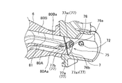
- the valve element 77 is composed of a disk-shaped butterfly valve portion 77a and a tumble flow path side closing valve portion 77b for opening and closing the tumble flow.
- the tumble passage side closing valve portion 77b is attached so as to form an angle with respect to the butterfly valve portion 77a when viewed in the axial direction of the throttle valve shaft 76, and is attached at right angles in this embodiment.
- the throttle valve shaft 76 is composed of a shaft portion 76a having a circular cross section and a mounting portion 76b having a plate-like tip at the tip of the shaft portion 76a.
- the valve body 77 is fixed to the mounting portion 76b of the throttle valve shaft 76 with a pair of screws 78 so as to substantially bisect the disk of the butterfly valve portion 77a.
- the butterfly valve portion 77a is divided into two halves with the throttle valve shaft 76 interposed therebetween, and is composed of a semi-disk-shaped one-end half body 77a1 on one side and a semi-disk-shaped other-end half body 77a2 on the other side. Become.
- the tumble channel side closing valve portion 77b of the valve body 77 is located on the opposite side of the butterfly valve portion 77a from where the throttle valve shaft 76 is attached, parallel to the throttle valve shaft 76, and at a position that bisects the butterfly valve portion 77a. In addition, it is arranged so as to form a right angle with respect to the butterfly valve portion 77a.
- the inlet opening 80Aa of the tumble flow path 80A of the intake passage 80 of the inlet pipe 6 connected to the downstream side of the intake passage 70 of the throttle body 7 is located on one end side of the butterfly valve portion 77a of the valve body 77.
- the inlet opening 80Ba of the main flow path 80B is positioned downstream of the other end half 77a1 of the butterfly valve portion 77a and opens.
- the inlet pipe 6 is provided with a fuel injection valve 87 which penetrates the main flow path 80B from above and is arranged to inject and supply fuel toward the intake valve port 40. be done.
- the fuel injection valve 87 is arranged in the inlet pipe 6, but a direct injection structure in which the fuel injection valve 87 is arranged in the cylinder head 32 or the cylinder block 31 to inject fuel into the combustion chamber 36 is also possible. good.
- the throttle valve 75 can be rotated counterclockwise in the drawings of FIGS. Further, the throttle valve 75 has a return spring (not shown) that causes the one end side half 77a1 of the rotating valve body 77 to abut against the inner surface 70a of the intake passage 70, and the other rotating end side half 77a2 to intake air. It is biased clockwise in the closing direction so as to be in a fully closed position abutting the inner surface 70a of the passage 70. As shown in FIG.
- FIG. 7 the operation of the throttle valve 75 and the flow of intake air in the intake passage 80 will be described with reference to FIGS. 7 to 16.
- FIG. 7 the operation of the throttle valve 75 and the flow of intake air in the intake passage 80 will be described with reference to FIGS. 7 to 16.
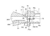
- the throttle valve shaft 76 When the driver gives an instruction to gradually open, the throttle valve shaft 76 is rotated counterclockwise against the biasing force of the spring, and the valve body 77 is opened as shown in FIG.
- the one end side half body 77a1 of the butterfly valve portion 77a is separated from the inner surface 70a of the air intake passage 70, and the other end side half body 77a2 is also separated from the inner surface 70a of the air intake passage 70 and gradually opened.
- the size of the opening 82 on the side of the tumble flow path 80A by the valve body 77 is substantially the same size as the size of the opening 83 on the side of the main flow path 80B.
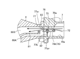
- FIG. 10 shows the flow of intake air in the intake passage 80 in the gradually opened state.
- the intake air flows from the upstream side of the intake passage 70 into the gap formed between the one end side half body 77a1 and the inner surface 70a of the intake passage 70 and the other end. It flows from the downstream side of the intake passage 70 to the intake passage 80 through the gap formed between the side half 77a2 and the inner surface 70a of the intake passage 70.
- a strong negative pressure is generated directly downstream of these gaps, and a wide negative pressure region is generated in the downstream range of the throttle valve 75 including the throttle valve shaft 76 .
- the cross-sectional area of the main flow path 80B is set larger than the cross-sectional area of the tumble flow path 80A.
- the momentum of the intake air is likely to weaken, and the intake air that has lost its momentum and has flowed into the main flow passage 80B having a large cross-sectional area is directly downstream of each end of the one end side half body 77a1 and the other end side half body 77a2 of the throttle valve 75.
- the intake air that flows backward is attracted together with the intake air that has passed through the throttle valve 75 and has a small cross-sectional area.
- the intake air flowing into the tumble flow path 80A and flowing through the tumble flow path 80A increases.
- the intake air flowing through the tumble flow path 80A passes above the head portion 46a of the intake valve 46, flows into the cylinder bore 31a, and generates a tumble vortex T in the combustion chamber 36 (see FIG. 4).
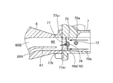
- the throttle valve shaft 76 is further rotated counterclockwise as shown in FIG.
- the one end side half body 77a1 and the other end side half body 77a2 are separated from the inner surface 70a of the air intake passage 70, and the opening 83 on the main flow passage 80B side and the opening 82 on the tumble flow passage 80A side are gradually opened. I'm going to die As shown in FIG. 12, the amount of intake air flowing to the main flow path 80B side increases, and the amount of intake air flowing to the tumble flow path 80A side also increases.
- the throttle valve shaft 76 is further rotated counterclockwise, and the butterfly valve portion 77a of the throttle valve 75 is opened.
- the one end half 77a1 is further separated from the inner surface 70a of the air intake passage 70 to enlarge the opening 83 of the main flow passage 80B.
- the tumble passage side closing valve portion 77b of the throttle valve 75 approaches the inner surface 70a of the intake passage 70, and the opening 82 on the tumble passage 80A side becomes smaller.
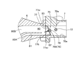
- the throttle valve shaft 76 When the throttle valve 75 is instructed to be fully opened by the driver's operation, such as during high-load operation, the throttle valve shaft 76 is further rotated counterclockwise, and the throttle valve 76 is opened as shown in FIG.
- the butterfly valve portion 77a of 75 is substantially parallel to the direction of the intake passage 70 and is in a fully open state, and the end of the tumble passage side closing valve portion 77b contacts the inner surface 70a of the intake passage 70 on the tumble passage 80A side. As a result, the lower half of the intake passage 70 is closed, and the opening 82 on the side of the tumble passage 80A is fully closed.
- the intake passage 80 connected to the combustion chamber 36 of the internal combustion engine 30 and the opening area of the intake passage 80 provided in the intake passage 80 are changed to change the amount of intake air flowing through the intake passage 80.
- a throttle valve 75 as a single intake air flow rate variable valve, and a tumble flow path 80A and a tumble flow formed in the intake passage 80 downstream of the throttle valve 75 so that the intake air generates a tumble swirl in the combustion chamber 36.
- the throttle valve 75 has a tumble flow passage side closing valve portion 77b that closes only the tumble flow passage 80A side.
- the opening 82 on the tumble flow path 80A side of the tumble flow path side closing valve portion 77b is made smaller as the opening 83 of the flow path 80B is increased.
- the amount of intake air flowing through the tumble flow path 80A can be decreased.
- a decrease in the amount of intake air introduced into the combustion chamber 36 can be suppressed by the interference between the flows of the two flow paths.
- the tumble flow path side closing valve portion 77b closes the opening 82 on the tumble flow path 82A side of the intake passage 80
- the one end side half 77a1 of the butterfly valve portion 77a of the throttle valve 75 moves toward the main flow path 80B side. Since the opening 83 is enlarged, the amount of intake air flowing through the main flow passage 80B is increased as the load increases, and the amount of intake air flowing through the tumble flow passage 80A is decreased. can gradually reduce the impact on the intake air passing through the
- the throttle valve 75 is composed of a butterfly valve portion 77a that closes the intake passage 80 and a tumble passage side closing valve portion 77b that closes only the tumble passage 80A, the tumble passage side closing valve portion The tumble channel 80A can be closed properly by 77b.
- the opening degree is increased in the direction in which the butterfly valve portion 77a becomes horizontal with respect to the intake passage 80. Accordingly, the opening 83 on the side of the tumble flow path 80A can be made smaller by the tumble flow path side closing valve portion 77b.
- the tumble flow path side closing valve portion 77b is separated from the upstream end 81a of the partition portion 81, the reverse flow effect of intake air when the throttle valve 75 is gradually opened is not hindered by the tumble flow path side closing valve portion 77b. .
- FIGS. 17 and 18A to 18D are schematic diagrams of the intake structure of the second embodiment, showing different opening states of the throttle valve 175.
- FIG. The drawing located on the right side of each drawing is a schematic diagram of the state of opening of the throttle valve 175 as seen from the upstream side of the throttle valve 175 .
- the throttle valve 75 as the variable intake flow rate valve is of the butterfly type, but in the intake structure of the second embodiment, As shown in FIG. 17, a shutter-type throttle valve 175 that slides in a direction intersecting the flow direction F of the intake air is used as the variable intake flow rate valve.
- the shutter type throttle valve 175 will be explained based on FIGS. 17 and 18A.
- the throttle body 107 is formed with a tubular guide portion 108 protruding from the throttle body 107 in a direction orthogonal to the intake flow direction F.
- a plate-like valve body 177 is fitted in the guide portion 108 so as to be slidable along the guide portion 108 .
- the guide portion 108 is composed of an upper guide portion 108a projecting upward from the throttle body 107 and a lower guide portion 108b projecting downward.
- a bottom portion 108c is formed at the end of the lower guide portion 108b so as to prevent the valve body 177 from falling off.
- a spring 178 is inserted into the guide portion 108 so as to contact the valve body 177 and the upper portion of the valve body 177, and a cap 179 is screwed to the end of the upper guide portion 108a.
- the spring 178 is inserted in a compressed state, and the valve body 177 is always urged toward the bottom portion 108c of the guide portion 108 by the spring 178. As shown in FIG.
- a wire 176 is attached to the top of the valve body 177 .
- the wire 176 extends from the through hole 179a of the cap 179 to the outside of the guide portion 108.
- the valve body 177 is moved to the guide portion 108. It slides up and down inside to open and close the throttle valve 175 .
- the partition 81 that partitions the intake passage 80 consists of an inlet pipe side partition 81A, an insulator side partition 81B, and an intake port side partition 81C. , was configured continuously from the upstream side to the downstream side of the intake air flow.
- a throttle body side partition 181D is formed in the throttle body 107, and the partition 181 that partitions the intake passage 180 is the throttle body side partition.
- the portion 181D, the inlet pipe side partition portion 181A, the insulator side partition portion 181B, and the intake port side partition portion 181C are configured continuously from the upstream side to the downstream side of the intake flow.
- the upstream end 181a of the partition 181 is in contact with the valve body 177, and the throttle body side partition 181D extends upstream.
- the intake passage 180 is partitioned into a tumble passage 108A and a main passage 180B by a partition portion 181, and the main passage 180B is formed to have a larger cross-sectional area than the tumble passage 180A.
- the valve body 177 is formed in a substantially rectangular shape when viewed from the front, and is provided with a through hole 177c at a predetermined position. As shown in FIG. 18C, the lateral width of the through hole 177c is set wider than the maximum lateral width of the intake passage 180. As shown in FIG. 18A, the valve body 177 is formed in a substantially rectangular shape when viewed from the front, and is provided with a through hole 177c at a predetermined position. As shown in FIG. 18C, the lateral width of the through hole 177c is set wider than the maximum lateral width of the intake passage 180. As shown in FIG.
- an intake passage blocking portion 177a that blocks both the tumble flow passage 80A and the main flow passage 80B of the intake passage 80.
- the intake passage blocking portion 177a is set to have a height and width that blocks both the tumble flow passage 80A and the main flow passage 80B when the valve body 177 abuts against the bottom portion 108c and is positioned at the lowest position.
- Below the through hole 177c of the valve body 177 as shown in FIG. 18D, there is a tumble channel side closing valve portion 177b that closes the tumble channel 80A when the main channel 180B is fully opened.
- the width and height of the tumble flow path side closing valve portion 177b are set so that the tumble flow path 180A is fully closed when the main flow path 180B is fully opened.
- valve body 177 is formed in a substantially rectangular shape when viewed from the front.
- the tumble passage side closing valve portion 177b may have another shape as long as it can close the tumble passage 180A.
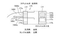
- FIGS. 18A to 18D show the state when the throttle valve 175 is fully closed
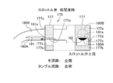
- FIG. 18B shows the state when the throttle valve 175 is at a low opening
- FIG. 18C shows the state when the throttle valve 175 is at a medium opening
- FIG. represents the state of
- FIG. 18A shows the state when the throttle valve 175 is fully closed. There is no instruction from the operator or the like to open the throttle valve 175, and the valve body 177 is pressed against the bottom portion 180c of the lower guide portion 108b by the biasing force of the spring 178. As shown in FIG. The through hole 177c of the valve body 177 is positioned below the tumble flow path 180A and the main flow path 180B, and both the tumble flow path 108A and the main flow path 180B are blocked by the intake passage blocking portion 177a of the valve body 177.
- FIG. 18B shows the state when the throttle valve 175 is at a low opening.
- the valve body 177 is moved upward by the wire 176, and while the tumble flow path 180A side is opened, the main flow path 180B is blocked by the intake passage blocking portion 177a. state.
- the throttle valve 175 when the throttle valve 175 is in a low opening state, the tumble flow path 180A side is open and the main flow path 180B is closed. It passes above 46a and flows into the cylinder bore 31a to generate a tumble vortex T in the combustion chamber 36 (see FIG. 17).
- the through hole 177c of the valve body 177 opens from the tumble flow path 180A side, while the main flow path 180B is blocked by the intake passage closed side portion 177a.
- FIG. 18C shows the state when the throttle valve 175 is at a middle opening.
- the valve element 177 moves further upward, and the tumble flow path 180A is fully opened, while the main flow path 180B is partially blocked by the intake passage blocking portion 177a and opened at the other portion.
- the opening 182 on the tumble flow path 180A side of the tumble flow path closing valve portion 177b becomes smaller as the opening 183 of the main flow path 180B increases.
- FIG. 18D shows the state when the throttle valve 175 is fully open.
- the through hole 177c of the valve body 177 is arranged so that the vertical opening width h1 of the through hole 177c is equal to or larger than the vertical width of the upstream opening 180Ba so as to correspond to the upstream opening 180Ba of the main flow path 180B. is set.
- the valve body 177 of the throttle valve 175 as the variable intake flow rate valve has a through hole 177c, and the valve body 177 moves through the guide portion 108 provided in the throttle body 107. , and slides in a direction intersecting the flow direction F of the intake air to change the opening ratio with respect to the intake passage 180 .
- the valve body 177c moves through the guide portion 108 provided in the throttle body 107. , and slides in a direction intersecting the flow direction F of the intake air to change the opening ratio with respect to the intake passage 180 .
- the main flow path 180B has a larger cross-sectional area than the tumble flow path 180A, and the through hole 177c has an opening width corresponding to the upstream opening 180Ba of the main flow path 180B. can be completely opened and the tumble channel 108A can be blocked.
- FIG. 19A and 19B show the state of the intake structure of the second embodiment when the throttle valve 175 is at a low opening.
- the upper surface 177c of the through hole 177c of the valve body 177 is formed in a direction substantially perpendicular to the moving direction of the valve body 177, and when the throttle valve 175 is in the state of FIG. 177d is located at the same height as the lower edge 181b of the upstream end 181a of the partition 181 that partitions the intake passage 180.
- the valve body 177 moves upward from the state shown in FIG. 19A and enters the state shown in FIG.
- the upper surface 177d of 177c only moves the tip surface of the upstream end 181a of the partition 181, and the throttle opening area does not change. Therefore, the instruction to increase the throttle opening is not reflected.
- FIGS. 20A to 20D A first modification of the intake structure of the second embodiment is shown in FIGS. 20A to 20D.
- 20A shows the state when the throttle valve 175 is fully closed
- FIG. 20B shows the state when the throttle valve 175 is gradually opened
- FIG. 20C shows the state when the throttle valve 175 is at a low opening
- FIG. 20A shows the state when the throttle valve 175 is fully closed
- FIG. 20B shows the state when the throttle valve 175 is gradually opened
- FIG. 20C shows the state when the throttle valve 175 is at a low opening
- a first modified example of the intake structure of the second embodiment uses a valve body 200 as shown in FIG. 20A.
- the valve body 200 has substantially the same structure as the valve body 177 used in the second embodiment, but as shown in FIG. It is formed so as to incline upward from the upper edge 200d1 toward the upper edge 200d2 on the downstream side, and the opening on the downstream side is formed larger than the opening on the upstream side.
- the upper edge 200d1 on the upstream side of the upper surface 200d of the through hole 200c is at the same height as the lower surface of the throttle body 107.
- the side upper edge 200d2 is positioned at the upstream end 181a of the partition 181.
- the upper edge portion 200d1 on the upstream side of the through hole 200c of the valve body 200 is located at the same height as the lower surface of the throttle body 107 from the tumble flow path 180A and the main flow path 180B, so the through hole 200c is closed. In this state, intake air does not flow through both the tumble flow path 108A and the main flow path 180B.
- FIG. 20B shows the state when the throttle valve 200 is gradually opened.
- the valve body 200 moves upward, and the upper edge portion 200d1 on the upstream side of the through hole 200c moves upward from the lower surface of the throttle body 107 and tumbles.
- the upper edge portion 200d2 on the downstream side is located at the upper edge of the upstream end 181a of the partition portion 181, and the main channel 180B is closed.
- FIG. 20C shows the state of the throttle valve 175 when the degree of opening is low.
- the valve body 200 moves further upward, and since the upper edge 200d1 on the upstream side of the through hole 200c is above the lower surface of the throttle body 107, the upstream side of the throttle valve 200 is opened and the upper side on the downstream side is opened.
- the edge portion 200d2 is positioned above the upper edge of the upstream end 181a of the partition portion 181, and the main flow path 180B is also opened so that the intake air flows through the tumble flow path 108A and the main flow path 108B.
- FIG. 20D shows the state when the throttle valve 175 is fully open.
- the valve body 177 is moved to the uppermost position, the opening 183 of the main flow path 180B is fully opened by the through hole 177c, the tumble flow path 180A is fully closed by the tumble flow path side closing valve portion 177b, and the intake air flows only through the main flow path 180B. flow into
- the first modification of the second embodiment is configured as described above, and as shown in FIG. is located above the lower surface of the throttle body 107 and opens from the tumble flow path 180A side, and the upper edge portion 200d2 on the downstream side is located at the upper edge of the upstream end 181a of the partition portion 181.
- FIG. 21 shows the state during the full opening of the throttle valve 175 of the first modified example of the intake structure of the second embodiment.
- the tumble flow path side closing valve portion 200b of the valve body 200 is positioned above the lower surface of the throttle body 107, and the dashed line
- a step may occur between the inner surface of the throttle body 107 and the tumble passage side closing valve portion 200b, which may increase airflow resistance of intake air and cause output loss.
- FIGS. 22A to 22D A second modification of the intake structure of the second embodiment is shown in FIGS. 22A to 22D.
- 22A shows the state when the throttle valve 175 is fully closed
- FIG. 22B shows the state when the throttle valve 175 is at a low opening
- FIG. 20C shows the state when the throttle valve 175 is at a medium opening
- FIG. ing shows the state when the throttle valve 175 is at a second modified example of the second embodiment in order to reduce the ventilation resistance of the intake air.
- FIGS. 22A to 22D A second modification of the intake structure of the second embodiment is shown in FIGS. 22A to 22D.
- 22A shows the state when the throttle valve 175 is fully closed
- FIG. 22B shows the state when the throttle valve 175 is at a low opening
- FIG. 20C shows the state when the throttle valve 175 is at a medium opening
- FIG. ing shows the state when the throttle valve 175 is at a medium opening
- a second modification of the intake structure of the second embodiment uses a valve body 201 as shown in FIG. 22A.
- the valve body 201 has substantially the same structure as the valve body 200 used in the first modification, but as shown in FIG. It is formed so as to incline upward from the edge 201e1 toward the lower edge 201e2 on the downstream side.
- FIG. 22D shows the state when the throttle valve 175 is fully open.
- the valve body 201 has been moved to the highest position.
- the through hole 177c of the valve body 177 is arranged so that the vertical opening width h2 of the through hole 177c is equal to or larger than the vertical width of the upstream opening 280Ba so as to correspond to the upstream opening 280Ba of the main flow path 280B. is set.
- the upper edge portion 201d1 on the upstream side of the through hole 201c is positioned at the same height as the upper surface of the throttle body 107, and the lower edge portion 201e1 on the upstream side of the lower surface 201e of the through hole 201c is positioned at the lower surface of the throttle body 107.
- the tumble flow path side closing valve portion 201b of the valve element 201 does not increase the ventilation resistance of the intake air, thereby eliminating the risk of output loss.
- FIGS. 24, 25 and 26 show the third, fourth and fifth modifications of the second embodiment, respectively.
- 23A to 23C are diagrams showing different states of the throttle valve 175 of the second modified example of the second embodiment.
- FIG. 23A shows the state when the throttle valve 175 of the second modified example is gradually opened. Due to the steps in the air intake, ventilation resistance was generated. Therefore, in the third modified example (see FIG. 24), the fourth modified example (see FIG. 25), and the fifth modified example (see FIG. 26), the shape of the tip of the partition portion 181 is changed so that the plate becomes thinner toward the upstream side. A partition portion 281 having a reduced thickness is used. A step between the upper surface 202d of the valve body 202 and the upstream end 281a of the partition portion 281 is eliminated, and airflow resistance of intake air can be prevented from occurring.
- FIG. 23B shows a state in which the throttle valve 175 of the second modification is half open.
- the difference in level between the upper surface of the throttle body 107 and the intake passage blocking portion 201a of the valve body 201 causes ventilation resistance of the intake air. Therefore, a valve body 203 like the fourth modification (see FIG. 25) is used.
- the upper surface 203d of the through hole 203c of the valve body 203 is formed such that the upper edge 203d1 on the upstream side and the upper edge 203d2 on the downstream side are at the same height , and the upper edge 203d3 of the intermediate portion is positioned downward. is doing. This eliminates the step between the upper surface of the throttle body 107 and the intake passage blocking portion 203a of the valve body 201, thereby preventing the occurrence of intake air flow resistance.
- FIG. 23C shows the state when the throttle valve 175 of the second modification is fully opened.
- the difference in level between the upper surface 201d of the through hole 201c of the valve body 201 and the wall surface of the intake passage 108 causes ventilation resistance of intake air. Therefore, an intake passage 280 like the fifth modification (see FIG. 26) is used.
- the wall surface of the main flow passage 208A of the intake passage 208 is made to extend upward, and when the throttle valve 175 is fully opened, the upper edge portion 202d2 on the downstream side of the upper surface 202d of the through hole 202c of the valve body 202 is at the same height.
- the opening 282 of the tumble flow path 280A becomes smaller. Since the fifth modification is configured as described above, the step between the upper surface 201d of the through hole 201c of the valve body 201 and the wall surface of the intake passage 108 can be eliminated, and the occurrence of intake air flow resistance can be prevented.
Landscapes
- Engineering & Computer Science (AREA)
- Chemical & Material Sciences (AREA)
- Combustion & Propulsion (AREA)
- Mechanical Engineering (AREA)
- General Engineering & Computer Science (AREA)
- Control Of Throttle Valves Provided In The Intake System Or In The Exhaust System (AREA)
- Cylinder Crankcases Of Internal Combustion Engines (AREA)
Priority Applications (2)
| Application Number | Priority Date | Filing Date | Title |
|---|---|---|---|
| JP2023509996A JP7493097B2 (ja) | 2021-03-30 | 2021-03-30 | 内燃機関の吸気構造 |
| PCT/JP2021/013730 WO2022208699A1 (ja) | 2021-03-30 | 2021-03-30 | 内燃機関の吸気構造 |
Applications Claiming Priority (1)
| Application Number | Priority Date | Filing Date | Title |
|---|---|---|---|
| PCT/JP2021/013730 WO2022208699A1 (ja) | 2021-03-30 | 2021-03-30 | 内燃機関の吸気構造 |
Publications (1)
| Publication Number | Publication Date |
|---|---|
| WO2022208699A1 true WO2022208699A1 (ja) | 2022-10-06 |
Family
ID=83458441
Family Applications (1)
| Application Number | Title | Priority Date | Filing Date |
|---|---|---|---|
| PCT/JP2021/013730 Ceased WO2022208699A1 (ja) | 2021-03-30 | 2021-03-30 | 内燃機関の吸気構造 |
Country Status (2)
| Country | Link |
|---|---|
| JP (1) | JP7493097B2 (https=) |
| WO (1) | WO2022208699A1 (https=) |
Cited By (1)
| Publication number | Priority date | Publication date | Assignee | Title |
|---|---|---|---|---|
| JP2025151091A (ja) * | 2024-03-27 | 2025-10-09 | 本田技研工業株式会社 | 内燃機関の吸気構造 |
Citations (5)
| Publication number | Priority date | Publication date | Assignee | Title |
|---|---|---|---|---|
| JPH108972A (ja) * | 1996-06-24 | 1998-01-13 | Nissan Motor Co Ltd | 内燃機関の吸気装置 |
| JP2000145467A (ja) * | 1998-09-07 | 2000-05-26 | Yamaha Motor Co Ltd | エンジンの吸気装置 |
| EP1167719A2 (de) * | 2000-06-28 | 2002-01-02 | AVL List GmbH | Brennkraftmaschine mit zumindest zwei Einlasskanälen pro Zylinder |
| JP2003515026A (ja) * | 1999-11-12 | 2003-04-22 | エフ・エー・フアウ・モトーレンテヒニック・ゲゼルシヤフト・ミト・ベシユレンクテル・ハフツング | ピストン内燃機関のシリンダに可変吸気運動を実行する設定ユニット |
| WO2019009061A1 (ja) * | 2017-07-05 | 2019-01-10 | 本田技研工業株式会社 | 内燃機関の吸気構造 |
-
2021
- 2021-03-30 JP JP2023509996A patent/JP7493097B2/ja active Active
- 2021-03-30 WO PCT/JP2021/013730 patent/WO2022208699A1/ja not_active Ceased
Patent Citations (5)
| Publication number | Priority date | Publication date | Assignee | Title |
|---|---|---|---|---|
| JPH108972A (ja) * | 1996-06-24 | 1998-01-13 | Nissan Motor Co Ltd | 内燃機関の吸気装置 |
| JP2000145467A (ja) * | 1998-09-07 | 2000-05-26 | Yamaha Motor Co Ltd | エンジンの吸気装置 |
| JP2003515026A (ja) * | 1999-11-12 | 2003-04-22 | エフ・エー・フアウ・モトーレンテヒニック・ゲゼルシヤフト・ミト・ベシユレンクテル・ハフツング | ピストン内燃機関のシリンダに可変吸気運動を実行する設定ユニット |
| EP1167719A2 (de) * | 2000-06-28 | 2002-01-02 | AVL List GmbH | Brennkraftmaschine mit zumindest zwei Einlasskanälen pro Zylinder |
| WO2019009061A1 (ja) * | 2017-07-05 | 2019-01-10 | 本田技研工業株式会社 | 内燃機関の吸気構造 |
Cited By (2)
| Publication number | Priority date | Publication date | Assignee | Title |
|---|---|---|---|---|
| JP2025151091A (ja) * | 2024-03-27 | 2025-10-09 | 本田技研工業株式会社 | 内燃機関の吸気構造 |
| JP7850757B2 (ja) | 2024-03-27 | 2026-04-23 | 本田技研工業株式会社 | 内燃機関の吸気構造 |
Also Published As
| Publication number | Publication date |
|---|---|
| JP7493097B2 (ja) | 2024-05-30 |
| JPWO2022208699A1 (https=) | 2022-10-06 |
Similar Documents
| Publication | Publication Date | Title |
|---|---|---|
| CN111065800B (zh) | 用于内燃机的进气结构 | |
| JP6714764B2 (ja) | 内燃機関の吸気構造 | |
| EP1655464B1 (en) | Engine | |
| JP4728195B2 (ja) | エンジンの吸気制御装置 | |
| EP2131034B1 (en) | Motor cycle | |
| WO2018163909A1 (ja) | 内燃機関の吸気装置 | |
| JP3153075U (ja) | 車両用エンジンユニットおよび鞍乗り型車両 | |
| JP6698223B2 (ja) | シリンダヘッド | |
| WO2022208699A1 (ja) | 内燃機関の吸気構造 | |
| JP7336587B2 (ja) | 内燃機関の吸気構造 | |
| EP3650671B1 (en) | Internal combustion engine intake structure | |
| JP6691564B2 (ja) | 内燃機関の吸気通路 | |
| JP6748782B2 (ja) | 内燃機関の吸気構造 | |
| JP7600426B2 (ja) | 内燃機関の吸気装置 | |
| JP7600425B2 (ja) | 内燃機関の吸気装置 | |
| JP7850757B2 (ja) | 内燃機関の吸気構造 | |
| US8997713B2 (en) | Throttle body configured to provide turbulent air flow to a combustion chamber of an engine, and engine including same | |
| JP2024105739A (ja) | 内燃機関の吸気装置 | |
| JP7575615B2 (ja) | 内燃機関の吸気構造 | |
| JP6564523B2 (ja) | 内燃機関の吸気装置 | |
| JP3320775B2 (ja) | エンジンの吸気制御装置 | |
| JP2025151090A (ja) | 内燃機関 | |
| JP2018150816A (ja) | 内燃機関の吸気装置 | |
| WO2024069940A1 (ja) | 内燃機関の吸気構造 |
Legal Events
| Date | Code | Title | Description |
|---|---|---|---|
| 121 | Ep: the epo has been informed by wipo that ep was designated in this application |
Ref document number: 21934868 Country of ref document: EP Kind code of ref document: A1 |
|
| ENP | Entry into the national phase |
Ref document number: 2023509996 Country of ref document: JP Kind code of ref document: A |
|
| WWE | Wipo information: entry into national phase |
Ref document number: 202317064284 Country of ref document: IN |
|
| NENP | Non-entry into the national phase |
Ref country code: DE |
|
| 122 | Ep: pct application non-entry in european phase |
Ref document number: 21934868 Country of ref document: EP Kind code of ref document: A1 |