WO2022208664A1 - 画像処理装置、画像処理方法、プログラム - Google Patents
画像処理装置、画像処理方法、プログラム Download PDFInfo
- Publication number
- WO2022208664A1 WO2022208664A1 PCT/JP2021/013581 JP2021013581W WO2022208664A1 WO 2022208664 A1 WO2022208664 A1 WO 2022208664A1 JP 2021013581 W JP2021013581 W JP 2021013581W WO 2022208664 A1 WO2022208664 A1 WO 2022208664A1
- Authority
- WO
- WIPO (PCT)
- Prior art keywords
- vehicle
- area
- image processing
- image
- pixel
- Prior art date
Links
- 238000003672 processing method Methods 0.000 title claims description 5
- 238000001514 detection method Methods 0.000 claims description 78
- 238000000034 method Methods 0.000 description 36
- 238000010586 diagram Methods 0.000 description 13
- 238000010801 machine learning Methods 0.000 description 9
- 238000004891 communication Methods 0.000 description 5
- 230000006870 function Effects 0.000 description 5
- 238000005516 engineering process Methods 0.000 description 2
- 230000015654 memory Effects 0.000 description 2
- 238000004364 calculation method Methods 0.000 description 1
- 238000004590 computer program Methods 0.000 description 1
- 239000004065 semiconductor Substances 0.000 description 1
Images


Classifications
-
- G—PHYSICS
- G06—COMPUTING; CALCULATING OR COUNTING
- G06V—IMAGE OR VIDEO RECOGNITION OR UNDERSTANDING
- G06V20/00—Scenes; Scene-specific elements
- G06V20/60—Type of objects
- G06V20/64—Three-dimensional objects
- G06V20/647—Three-dimensional objects by matching two-dimensional images to three-dimensional objects
-
- B—PERFORMING OPERATIONS; TRANSPORTING
- B60—VEHICLES IN GENERAL
- B60W—CONJOINT CONTROL OF VEHICLE SUB-UNITS OF DIFFERENT TYPE OR DIFFERENT FUNCTION; CONTROL SYSTEMS SPECIALLY ADAPTED FOR HYBRID VEHICLES; ROAD VEHICLE DRIVE CONTROL SYSTEMS FOR PURPOSES NOT RELATED TO THE CONTROL OF A PARTICULAR SUB-UNIT
- B60W40/00—Estimation or calculation of non-directly measurable driving parameters for road vehicle drive control systems not related to the control of a particular sub unit, e.g. by using mathematical models
- B60W40/02—Estimation or calculation of non-directly measurable driving parameters for road vehicle drive control systems not related to the control of a particular sub unit, e.g. by using mathematical models related to ambient conditions
-
- G—PHYSICS
- G06—COMPUTING; CALCULATING OR COUNTING
- G06V—IMAGE OR VIDEO RECOGNITION OR UNDERSTANDING
- G06V10/00—Arrangements for image or video recognition or understanding
- G06V10/20—Image preprocessing
- G06V10/26—Segmentation of patterns in the image field; Cutting or merging of image elements to establish the pattern region, e.g. clustering-based techniques; Detection of occlusion
-
- G—PHYSICS
- G06—COMPUTING; CALCULATING OR COUNTING
- G06V—IMAGE OR VIDEO RECOGNITION OR UNDERSTANDING
- G06V10/00—Arrangements for image or video recognition or understanding
- G06V10/40—Extraction of image or video features
- G06V10/42—Global feature extraction by analysis of the whole pattern, e.g. using frequency domain transformations or autocorrelation
- G06V10/421—Global feature extraction by analysis of the whole pattern, e.g. using frequency domain transformations or autocorrelation by analysing segments intersecting the pattern
-
- G—PHYSICS
- G06—COMPUTING; CALCULATING OR COUNTING
- G06V—IMAGE OR VIDEO RECOGNITION OR UNDERSTANDING
- G06V10/00—Arrangements for image or video recognition or understanding
- G06V10/70—Arrangements for image or video recognition or understanding using pattern recognition or machine learning
- G06V10/77—Processing image or video features in feature spaces; using data integration or data reduction, e.g. principal component analysis [PCA] or independent component analysis [ICA] or self-organising maps [SOM]; Blind source separation
- G06V10/80—Fusion, i.e. combining data from various sources at the sensor level, preprocessing level, feature extraction level or classification level
- G06V10/809—Fusion, i.e. combining data from various sources at the sensor level, preprocessing level, feature extraction level or classification level of classification results, e.g. where the classifiers operate on the same input data
-
- G—PHYSICS
- G06—COMPUTING; CALCULATING OR COUNTING
- G06V—IMAGE OR VIDEO RECOGNITION OR UNDERSTANDING
- G06V20/00—Scenes; Scene-specific elements
- G06V20/50—Context or environment of the image
- G06V20/56—Context or environment of the image exterior to a vehicle by using sensors mounted on the vehicle
- G06V20/58—Recognition of moving objects or obstacles, e.g. vehicles or pedestrians; Recognition of traffic objects, e.g. traffic signs, traffic lights or roads
-
- G—PHYSICS
- G06—COMPUTING; CALCULATING OR COUNTING
- G06V—IMAGE OR VIDEO RECOGNITION OR UNDERSTANDING
- G06V20/00—Scenes; Scene-specific elements
- G06V20/50—Context or environment of the image
- G06V20/56—Context or environment of the image exterior to a vehicle by using sensors mounted on the vehicle
- G06V20/588—Recognition of the road, e.g. of lane markings; Recognition of the vehicle driving pattern in relation to the road
-
- G—PHYSICS
- G08—SIGNALLING
- G08G—TRAFFIC CONTROL SYSTEMS
- G08G1/00—Traffic control systems for road vehicles
- G08G1/16—Anti-collision systems
Definitions
- the present invention relates to an image processing device, an image processing method, and a program.
- Patent Document 1 discloses a technique for determining a vehicle existence area based on overlapping of vehicle existence areas detected by two devices, a camera and a laser radar.
- an object of the present invention is to provide an image processing device, an image processing method, and a program that solve the above problems.
- an image processing apparatus includes area recognition means for recognizing to which of a plurality of designated different area classes related to a subject a subject in each pixel of an acquired photographed image belongs. acquiring distance information of each pixel of the area in the captured image indicating the area class of the vehicle among the plurality of different area classes from the depth map information corresponding to the captured image, and determining continuity of the distance information; vehicle detection means for determining a position where the line is interrupted as a boundary between different vehicles.
- an image processing method recognizes to which of a plurality of different area classes designated for a subject a subject in each pixel of an acquired photographed image belongs, and In a region in the captured image that indicates the vehicle region class among the different region classes, the distance information of each pixel in the region is obtained from the depth map information corresponding to the captured image, and the position where the continuity of the distance information is interrupted is determined. It is judged as a boundary between different vehicles.
- the program causes the computer of the image processing apparatus to recognize to which of a plurality of designated different area classes related to the subject the subject of each pixel of the acquired photographed image belongs.
- an area recognizing means for acquiring distance information of each pixel in an area in the photographed image indicating an area class of a vehicle among the plurality of different area classes from depth map information corresponding to the photographed image; It functions as vehicle detection means for determining a position where continuity of information is interrupted as a boundary between different vehicles.
- images can be used to recognize vehicles that cannot be recognized by pattern matching or machine learning.
- FIG. 1 is a diagram showing an outline of an image processing system according to this embodiment
- FIG. 2 is a hardware configuration diagram of the image processing apparatus according to the embodiment
- FIG. 1 is a functional block diagram of an image processing apparatus according to this embodiment
- FIG. FIG. 3 is a diagram showing an outline of processing of the image processing apparatus according to the embodiment; It is a figure which shows the processing flow of the image processing apparatus by this embodiment.
- 1 is a diagram showing the minimum configuration of an image processing apparatus according to this embodiment
- FIG. FIG. 3 is a diagram showing a processing flow of the image processing apparatus with the minimum configuration according to the embodiment;
- FIG. 1 is a diagram showing an overview of an image processing system including an image processing apparatus according to this embodiment.
- an image processing system 100 is configured by connecting an image processing device 1 mounted on a vehicle 20 and a camera 2 via a wireless communication network or a wired communication network.
- the image processing system 100 may include the server device 3 .
- the server device 3 may be connected for communication with the image processing device 1 and the camera 2 .
- the camera 2 captures an image including a road and vehicles traveling on the road.
- Camera 2 outputs an image to image processing device 1 .
- the image processing device 1 uses the image acquired from the camera 2 to recognize the vehicle appearing in the image.
- FIG. 2 is a hardware configuration diagram of the image processing apparatus.
- the image processing apparatus 1 includes a CPU (Central Processing Unit) 101, a ROM (Read Only Memory) 102, a RAM (Random Access Memory) 103, an HDD (Hard Disk Drive) 104, a communication module 105, and a database 106. It is a computer provided with each hardware such as. Note that the server device 3 also has a similar configuration.
- FIG. 3 is a functional block diagram of the image processing apparatus.
- the image processing apparatus 1 is activated when the vehicle 20 is powered on, and executes an image processing program stored in advance.
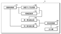
- the image processing device 1 includes the functions of an image acquisition unit 11, a depth map generation unit 12, an area recognition unit 13, a first vehicle detection unit 14, a second vehicle detection unit 15, a matching processing unit 16, and an output unit 17. demonstrate.
- the image acquisition unit 11 acquires images from the camera 2 .
- the depth map generator 12 uses the image acquired from the camera 2 to generate depth map information.
- the depth map information is information that holds information about the distance to the subject of the camera 2 based on the image acquired from the camera 2 for each pixel of the image.
- the region recognition unit 13 recognizes to which of a plurality of designated different region classes related to the subject the subject of each pixel of the acquired image belongs.
- the first vehicle detection unit 14 acquires the distance information of each pixel in the area in the image indicating the area class of the vehicle from the depth map information, and detects the position where the continuity of the distance information is interrupted as the boundary between different vehicles. One area of the vehicle is specified based on the boundary and the distance information indicated by each pixel indicating the area class of the vehicle.
- the second vehicle detection unit 15 uses pattern matching or a vehicle recognition model obtained by machine learning to identify the area of the vehicle captured in the captured image or the depth map information.
- the matching processing unit 16 identifies the area of each vehicle in the captured image based on the recognition results of the first vehicle detection unit 14 and the second vehicle detection unit 15 .
- the output unit 17 outputs the processing result of the collation processing unit 16 .
- the first vehicle detection unit 14 determines that the area of one vehicle is in contact with the area of the area class indicating the road based on the positional relationship between the area of the one vehicle and the area of the area class indicating the road among the area classes. If not, exclude the area of the vehicle from the area of the vehicle. Further, the first vehicle detection unit 14 determines whether the size of the area of one vehicle corresponds to the size of the vehicle. exclude.
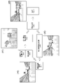
- FIG. 4 is a diagram showing an outline of processing of the image processing apparatus.
- FIG. 4 shows a photographed image (40) acquired from the camera by the image processing device 1, a processing result (41) of the processing (first vehicle detection processing) of the first vehicle detection unit 14, and the second vehicle detection unit 15. (second vehicle detection process) and a process result (43) of the collation process.
- a truck is recognized in the processing result (41) of the first vehicle detection processing.
- the image processing device 1 acquires a captured image (S1).
- the depth map generation unit 12 generates depth map information using the captured image (S2), and recognizes to which of a plurality of designated different area classes related to the object appearing in the captured image each pixel of the captured image belongs. (S3).
- the image processing device 1 performs a first vehicle detection process (S4).
- This first vehicle detection process can detect, for example, a large vehicle that is difficult to recognize in the second vehicle detection process.
- the image processing device 1 performs a second vehicle detection process (S5). It is assumed that vehicles other than large vehicles are detected in this second detection image.
- the image processing apparatus 1 uses the processing result (41) of the first vehicle detection processing and the processing result (42) of the second vehicle detection processing to determine the areas of the vehicle that can be recognized in each image in duplicate.
- a vehicle recognition result (43) is generated (S6).
- the image processing device 1 outputs the vehicle recognition result (43).
- This output destination may be a storage device such as the database 106 .
- FIG. 5 is a diagram showing the processing flow of the image processing apparatus.
- the processing flow of the image processing apparatus 1 will be described step by step below.
- the camera 2 outputs a photographed image generated by photographing to the image processing device 1 .
- the image acquisition unit 11 of the image processing device 1 acquires an image and outputs it to the depth map generation unit 12 .
- the depth map generator 12 generates depth map information based on the captured image (step S101). Note that the image acquisition unit 11 may acquire depth map information generated by the camera 2 in advance. In this case, the depth map generator 12 may not be provided in the image processing device 1 .
- the depth map information is an image in which pixels in the image contain information about the distance from the camera 2 to the subject. Depth map information may be generated by a known technique.
- the depth map generator 12 outputs depth map information to the first vehicle detector 14 .
- the area recognition unit 13 acquires the captured image and the depth map information.
- the area recognition unit 13 recognizes the subject in the captured image for each area class such as sky, wall, road, moving object (traffic participant), and person (step S102).
- a known technique may be used as the technique for the area recognition unit 13 to recognize the captured image for each area class indicating a plurality of different objects.
- the area recognition unit 13 generates area recognition information that holds the probability that each pixel of the captured image belongs to each area class.
- the area recognition information is arrangement information of probability information for each area class for each pixel of the captured image.
- the area recognition unit 13 outputs probability information for each area class of each pixel to the first vehicle detection unit 14 .
- the region recognition unit 13 receives a captured image as an input and outputs the probability that each pixel of the captured image belongs to a plurality of predetermined region classes. can be calculated.
- the area class calculation model may be, for example, a model obtained by machine-learning the relationship between a large number of images as input, information indicating the area class of each pixel of the images as correct data, and the relationship therebetween.
- the first vehicle detection unit 14 acquires a captured image and depth map information including probability information for each area class for each pixel of the captured image.
- the first vehicle detection unit 14 identifies an area of pixels that is estimated to be a vehicle when the probability of the vehicle area class in the captured image is equal to or greater than a threshold. This area is called a vehicle estimation area.
- the first vehicle detection unit 14 compares the distance information between adjacent pixels for each pixel included in the vehicle estimation region, and determines that the distance difference between the adjacent pixels is equal to or less than a predetermined distance difference that is considered to be the same object.
- the first vehicle detection unit 14 identifies, as a region of one vehicle, a group of adjacent pixels in which the distance difference between adjacent pixels is equal to or less than a predetermined distance difference that is regarded as the same object (step S103 ). In addition, the first vehicle detection unit 14 identifies adjacent pixels having a distance difference equal to or greater than a predetermined distance difference, which is considered to be the same object, in the vehicle estimation region, and determines whether the distance between the adjacent pixels is the same as that of the vehicle. A boundary or a boundary between a vehicle and an object other than the vehicle may be determined to identify the area of one vehicle.
- the image processing apparatus 1 acquires distance information for each pixel in an area in a photographed image that indicates the area class of a vehicle, and determines a position where the continuity of the distance information is interrupted as a boundary between different vehicles. This is one aspect of the processing to be performed.
- the first vehicle detection unit 14 determines that the area of the vehicle is of the area class indicating the road. If the vehicle does not touch the area, the area of the vehicle may be excluded from the area of the vehicle. The first vehicle detection unit 14 determines whether the probability of an area of an area class in which the pixels below the pixels forming the lower side of the rectangular range indicating the area of one vehicle indicate a road is greater than or equal to a threshold.
- the first vehicle detection unit 14 when the probability of the region class indicating the road of the pixel adjacent to the lower side of the pixels forming the lower side of the rectangular range indicating the region of one vehicle is equal to or greater than the threshold, It is determined that the area of one vehicle is in contact with the area class indicating the road. Further, as an example, the first vehicle detection unit 14 determines that when the probability of the region class indicating the road of the pixels adjacent to the lower side of the pixels forming the lower side of the rectangular range indicating the region of one vehicle is less than the threshold, , the area of one vehicle is not in contact with the area of the area class indicating the road.
- the first vehicle detection unit 14 compares the length of the side of the rectangular range including the area of one vehicle specified in the above process with the side length range of the size corresponding to the vehicle.
- the side length of the rectangular range including the region of one vehicle specified in the above process is not included in the side length range of the size corresponding to the vehicle, the first vehicle detection unit 14 , the area indicated by the rectangular range may be determined not to be the vehicle area and excluded from the vehicle area.
- the first vehicle detection unit 14 generates the processing result (41) of the first vehicle detection process including the coordinate information of the rectangular range indicating the area finally specified as the area of one vehicle (step S104).
- the first vehicle detection unit 14 performs the same processing to generate the processing result of the first vehicle detection processing including the coordinate information of the rectangular range of the region of each of the plurality of vehicles.
- the first vehicle detection unit 14 outputs the processing result ( 41 ) of the first vehicle detection processing to the matching processing unit 16 .
- the processing of the first vehicle detection unit 14 by using the depth map information and the area class information of each pixel in the captured image, it is possible to detect special vehicles and nearby vehicles that are difficult to recognize by pattern matching or machine learning. It is possible to detect a large vehicle running on the road or a vehicle that is partially hidden.
- the second vehicle detection part 15 acquires the captured image from the image acquisition part 11 and performs the second vehicle detection process. Specifically, the second vehicle detection unit 15 uses a pattern matching technique to identify the area of the vehicle that appears in the captured image. Alternatively, the second vehicle detection unit 15 inputs the acquired photographed image to a vehicle recognition model generated by machine learning of the vehicle appearing in the photographed image in the past machine learning process. The second vehicle detection unit 15 acquires a vehicle recognition result after inputting the photographed image into the vehicle recognition model. The second vehicle detection unit 15 specifies the area of the vehicle appearing in the captured image recorded in the vehicle recognition result. The second vehicle detection unit 15 may identify multiple vehicle areas in the captured image.
- the second vehicle detection unit 15 generates the processing result (42) of the second vehicle detection process including the coordinate information of the rectangular range indicating the area specified as the vehicle area (step S105).
- the second vehicle detection unit 15 outputs the processing result ( 42 ) of the second vehicle detection processing to the matching processing unit 16 .
- the matching processing unit 16 acquires the processing result (41) of the first vehicle detection processing and the processing result (42) of the second vehicle detection processing.
- the collation processing unit 16 compares the vehicle area included in the processing result (41) of the first vehicle detection process and the vehicle area included in the processing result (42) of the second vehicle detection process, and compares the area of the vehicle included in the process result (42) of the second vehicle detection process.
- a region that overlaps above is specified in each processing result (step S106).
- the matching process unit 16 identifies them as one vehicle area. judge.
- the area where each detection result is compared and overlaps with a predetermined size or more is defined as an area where the corresponding vehicle areas in the photographed images indicated by each detection result are overlapped and the positions of these areas are almost the same. , or each region may overlap at a predetermined rate or more in the rectangles of the specified vehicle region.
- the collation processing unit 16 compares the coordinates in the image indicating the area (rectangle) of one or more vehicles specified only in the processing result (41) of the first vehicle detection processing and the processing result of the second vehicle detection processing.
- the coordinates in the image indicating the area (rectangle) of one or more vehicles specified only in (42), the processing result (41) of the first vehicle detection processing, and the processing result (42) of the second vehicle detection processing ), the vehicle recognition result including the coordinates in the image indicating the area determined to be one area overlapping by a predetermined size or more and the photographed image is output to the output unit 17 (step S107).
- the output unit 17 records the vehicle recognition result in the database 106 . Accordingly, the user can confirm the photographed image and the region of the vehicle recognized in the photographed image by the first vehicle detection process and the second vehicle detection process based on the vehicle recognition result.
- the output unit 17 generates a recognition result image by updating the color of the rectangle of the region of the captured image to the highlight color based on the coordinates of the region of the vehicle included in the vehicle recognition result obtained from the matching processing unit 16.
- a recognition result image may be generated and output by superimposing a rectangular image surrounding the area of the captured image on the captured image.
- the output destination of the vehicle recognition result and the recognition result image of the output unit 17 may be the server device 3, another display device, a user terminal, or the like.
- the image processing device 1 provided in the vehicle performs the above processing, but the drive recorder equipped with the camera 2 and the external server device 3 have the same functions as the image processing device 1,
- the area of the vehicle may be identified in the captured image in the same manner as the above process.
- FIG. 6 is a diagram showing the minimum configuration of the image processing apparatus.
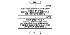
- FIG. 7 is a diagram showing the processing flow of the image processing apparatus with the minimum configuration.
- the image processing apparatus 1 includes at least area recognition means 61 and vehicle detection means 62 .
- the area recognition means 61 recognizes to which of a plurality of different area classes designated for the subject the subject of each pixel of the captured image belongs (step S701).
- the vehicle detection means 62 acquires distance information of each pixel in an area in the depth map information indicating the area class of the vehicle among a plurality of different area classes, and detects the position where the continuity of the distance information is interrupted. (step S702).
- Each of the devices mentioned above has a computer system inside.
- Each process described above is stored in a computer-readable recording medium in the form of a program, and the above process is performed by reading and executing this program by a computer.
- the computer-readable recording medium refers to magnetic disks, magneto-optical disks, CD-ROMs, DVD-ROMs, semiconductor memories, and the like.
- the computer program may be distributed to a computer via a communication line, and the computer receiving the distribution may execute the program.
- the above program may be for realizing part of the functions described above. Further, it may be a so-called difference file (difference program) that can realize the above-described functions in combination with a program already recorded in the computer system.
- difference file difference program
Abstract
Description
図1は本実施形態による画像処理装置を含む画像処理システムの概要を示す図である。
図1で示すように画像処理システム100は、車両20に搭載された画像処理装置1とカメラ2とが、無線通信ネットワークや有線通信ネットワークを介して接続されることにより構成される。画像処理システム100にはサーバ装置3が含まれてよい。サーバ装置3は、画像処理装置1やカメラ2と通信接続してよい。カメラ2は本実施形態においては、道路と当該道路を走行する車両を含む画像を撮影する。カメラ2は画像を画像処理装置1へ出力する。画像処理装置1はカメラ2から取得した画像を用いて、当該画像に写る車両を認識する。
この図が示すように画像処理装置1は、CPU(Central Processing Unit)101、ROM(Read Only Memory)102、RAM(Random Access Memory)103、HDD(Hard Disk Drive)104、通信モジュール105、データベース106等の各ハードウェアを備えたコンピュータである。なおサーバ装置3も同様の構成を備える。
画像処理装置1は車両20の始動に基づいて電源が投入されると起動し、予め記憶する画像処理プログラムを実行する。これにより画像処理装置1には、画像取得部11、深度マップ生成部12、領域認識部13、第一車両検出部14、第二車両検出部15、照合処理部16、出力部17の各機能を発揮する。
深度マップ生成部12は、カメラ2から取得した画像を用いて深度マップ情報を生成する。深度マップ情報は、カメラ2から取得した画像に基づいてカメラ2被写体までの距離情報を画像の各画素について保持する情報である。
領域認識部13は、取得した画像の各画素の被写体が、当該被写体に関する指定された複数の異なる領域クラスの何れに属するかを認識する。
第一車両検出部14は、車両の領域クラスを示す画像中の領域において当該領域の各画素の距離情報を深度マップ情報から取得し、当該距離情報の連続性が途切れる位置を異なる車両の境界と判定し、その境界と車両の領域クラスを示す各画素が示す距離情報とに基づいて車両の1台の領域を特定する。
第二車両検出部15は、パターンマッチングや、機械学習して得た車両認識モデルを用いて撮影画像、または深度マップ情報中に写る車両の領域を特定する。
照合処理部16は、第一車両検出部14と第二車両検出部15との認識結果に基づいて、撮影画像に写る各車両の領域を特定する。
出力部17は、照合処理部16の処理結果を出力する。
図4には、画像処理装置1がカメラから取得した撮影画像(40)と、第一車両検出部14の処理(第一車両検出処理)の処理結果(41)と、第二車両検出部15の処理(第二車両検出処理)の処理結果(42)と、照合処理の処理結果(43)とを示す。第一車両検出処理の処理結果(41)ではトラックが認識される。画像処理装置1は撮影画像を取得する(S1)。深度マップ生成部12は撮影画像を用いて深度マップ情報を生成し(S2)、撮影画像の各画素が、撮影画像に写る対象物に関する指定された複数の異なる領域クラスの何れに属するかを認識する(S3)。画像処理装置1は、第一車両検出処理(S4)を行う。この第一車両検出処理では、例えば第二車両検出処理では認識が難しい大型車両などが検出できる。画像処理装置1は、第二車両検出処理(S5)を行う。この第二検出画像には大型車両以外の車両が検出できているとする。画像処理装置1は第一車両検出処理の処理結果(41)と第二車両検出処理の処理結果(42)の各処理結果を用いて、重複してそれぞれの画像に認識できた車両の領域を含む車両認識結果(43)を生成する(S6)。画像処理装置1は車両認識結果(43)を出力する。この出力先はデータベース106などの記憶装置であってよい。
以下、画像処理装置1の処理フローについて順を追って説明する。
車両20が走行中、カメラ2は撮影により生成した撮影画像を画像処理装置1へ出力する。画像処理装置1の画像取得部11は画像を取得して深度マップ生成部12へ出力する。深度マップ生成部12は、取得した撮影画像に基づいて深度マップ情報を生成する(ステップS101)。なお画像取得部11は、予めカメラ2が生成した深度マップ情報を取得してよい。この場合、画像処理装置1に深度マップ生成部12は設けなくてもよい。深度マップ情報は、画像中の画素にカメラ2から被写体までの距離の情報が含まれる画像である。深度マップ情報の生成は公知の技術により行われてよい。深度マップ生成部12は深度マップ情報を第一車両検出部14へ出力する。
図7は最小構成の画像処理装置の処理フローを示す図である。
画像処理装置1は、少なくとも、領域認識手段61と、車両検出手段62とを備える。
領域認識手段61は、取得した撮影画像の各画素の被写体が、当該被写体に関する指定された複数の異なる領域クラスの何れに属するかを認識する(ステップS701)。
車両検出手段62は、複数の異なる領域クラスのうち車両の領域クラスを示す深度マップ情報中の領域において当該領域の各画素の距離情報を取得し、当該距離情報の連続性が途切れる位置を異なる車両の境界と判定する(ステップS702)。
2・・・カメラ
3・・・サーバ装置
11・・・画像取得部
12・・・深度マップ生成部
13・・・領域認識部
14・・・第一車両検出部
15・・・第二車両検出部
16・・・照合処理部
17・・・出力部
Claims (7)
- 取得した撮影画像の各画素の被写体が、当該被写体に関する指定された複数の異なる領域クラスの何れに属するかを認識する領域認識手段と、
前記複数の異なる領域クラスのうち車両の領域クラスを示す前記撮影画像中の領域において当該領域の各画素の距離情報を前記撮影画像に対応する深度マップ情報から取得し、当該距離情報の連続性が途切れる位置を異なる車両の境界と判定する車両検出手段と、
を備える画像処理装置。 - 前記撮影装置から取得した前記撮影画像に基づいて前記撮影装置から前記撮影画像に写る被写体までの距離情報を前記撮影画像の各画素について保持する前記深度マップ情報を生成する深度マップ生成手段と、
を備える請求項1に記載の画像処理装置。 - 前記車両検出手段は、前記連続性が途切れる位置と、前記車両の領域クラスを示す領域の各画素が示す距離情報とに基づいて前記車両の1台の領域を特定する
請求項1または請求項2に記載の画像処理装置。 - 前記車両検出手段は、前記車両1台の領域と、前記領域クラスのうち道路を示す領域クラスの領域との位置関係に基づいて、前記車両1台の領域が前記道路を示す領域クラスの領域に接していない場合に、当該車両1台の領域を前記車両の領域から除外する
請求項3に記載の画像処理装置。 - 前記車両検出手段は、前記車両1台の領域の大きさが、車両に相当する大きさかを判定し、車両に相当する大きさでない場合に、当該車両1台の領域を前記車両の領域から除外する
請求項1から請求項4の何れか一項に記載の画像処理装置。 - 取得した撮影画像の各画素の被写体が、当該被写体に関する指定された複数の異なる領域クラスの何れに属するかを認識し、
前記複数の異なる領域クラスのうち車両の領域クラスを示す前記撮影画像中の領域において当該領域の各画素の距離情報を前記撮影画像に対応する深度マップ情報から取得し、当該距離情報の連続性が途切れる位置を異なる車両の境界と判定する
画像処理方法。 - 画像処理装置のコンピュータを、
取得した撮影画像の各画素の被写体が、当該被写体に関する指定された複数の異なる領域クラスの何れに属するかを認識する領域認識手段、
前記複数の異なる領域クラスのうち車両の領域クラスを示す前記撮影画像中の領域において当該領域の各画素の距離情報を前記撮影画像に対応する深度マップ情報から取得し、当該距離情報の連続性が途切れる位置を異なる車両の境界と判定する車両検出手段、
として機能させるプログラム。
Priority Applications (3)
| Application Number | Priority Date | Filing Date | Title |
|---|---|---|---|
| PCT/JP2021/013581 WO2022208664A1 (ja) | 2021-03-30 | 2021-03-30 | 画像処理装置、画像処理方法、プログラム |
| JP2023509969A JPWO2022208664A1 (ja) | 2021-03-30 | 2021-03-30 | |
| EP21934835.6A EP4270357A4 (en) | 2021-03-30 | 2021-03-30 | IMAGE PROCESSING DEVICE, IMAGE PROCESSING METHOD AND PROGRAM |
Applications Claiming Priority (1)
| Application Number | Priority Date | Filing Date | Title |
|---|---|---|---|
| PCT/JP2021/013581 WO2022208664A1 (ja) | 2021-03-30 | 2021-03-30 | 画像処理装置、画像処理方法、プログラム |
Publications (1)
| Publication Number | Publication Date |
|---|---|
| WO2022208664A1 true WO2022208664A1 (ja) | 2022-10-06 |
Family
ID=83458439
Family Applications (1)
| Application Number | Title | Priority Date | Filing Date |
|---|---|---|---|
| PCT/JP2021/013581 WO2022208664A1 (ja) | 2021-03-30 | 2021-03-30 | 画像処理装置、画像処理方法、プログラム |
Country Status (3)
| Country | Link |
|---|---|
| EP (1) | EP4270357A4 (ja) |
| JP (1) | JPWO2022208664A1 (ja) |
| WO (1) | WO2022208664A1 (ja) |
Citations (6)
| Publication number | Priority date | Publication date | Assignee | Title |
|---|---|---|---|---|
| JPH08329393A (ja) | 1995-05-29 | 1996-12-13 | Daihatsu Motor Co Ltd | 先行車検出装置 |
| JP2009037622A (ja) * | 2007-08-03 | 2009-02-19 | Harman Becker Automotive Systems Gmbh | 画像を評価するための方法および装置 |
| JP2018194912A (ja) * | 2017-05-12 | 2018-12-06 | トヨタ自動車株式会社 | 路上障害物検出装置,方法,およびプログラム |
| JP2020502685A (ja) * | 2016-12-20 | 2020-01-23 | トヨタ・モーター・ヨーロッパToyota Motor Europe | パッシブ光学センサの画像データを増大させるための電子デバイス、システムおよび方法 |
| JP2020064583A (ja) * | 2018-10-17 | 2020-04-23 | 財団法人車輌研究測試中心 | 車両検出方法、動的光強度に基づく夜間の車両検出方法及びそのシステム |
| JP2020516853A (ja) * | 2016-12-09 | 2020-06-11 | トムトム グローバル コンテント ベスローテン フエンノートシャップ | ビデオベースの位置決め及びマッピングの方法及びシステム |
Family Cites Families (1)
| Publication number | Priority date | Publication date | Assignee | Title |
|---|---|---|---|---|
| EP2963633A4 (en) * | 2013-02-27 | 2016-12-07 | Hitachi Automotive Systems Ltd | OBJECT SENSOR |
-
2021
- 2021-03-30 WO PCT/JP2021/013581 patent/WO2022208664A1/ja active Application Filing
- 2021-03-30 JP JP2023509969A patent/JPWO2022208664A1/ja active Pending
- 2021-03-30 EP EP21934835.6A patent/EP4270357A4/en active Pending
Patent Citations (6)
| Publication number | Priority date | Publication date | Assignee | Title |
|---|---|---|---|---|
| JPH08329393A (ja) | 1995-05-29 | 1996-12-13 | Daihatsu Motor Co Ltd | 先行車検出装置 |
| JP2009037622A (ja) * | 2007-08-03 | 2009-02-19 | Harman Becker Automotive Systems Gmbh | 画像を評価するための方法および装置 |
| JP2020516853A (ja) * | 2016-12-09 | 2020-06-11 | トムトム グローバル コンテント ベスローテン フエンノートシャップ | ビデオベースの位置決め及びマッピングの方法及びシステム |
| JP2020502685A (ja) * | 2016-12-20 | 2020-01-23 | トヨタ・モーター・ヨーロッパToyota Motor Europe | パッシブ光学センサの画像データを増大させるための電子デバイス、システムおよび方法 |
| JP2018194912A (ja) * | 2017-05-12 | 2018-12-06 | トヨタ自動車株式会社 | 路上障害物検出装置,方法,およびプログラム |
| JP2020064583A (ja) * | 2018-10-17 | 2020-04-23 | 財団法人車輌研究測試中心 | 車両検出方法、動的光強度に基づく夜間の車両検出方法及びそのシステム |
Non-Patent Citations (1)
| Title |
|---|
| See also references of EP4270357A4 |
Also Published As
| Publication number | Publication date |
|---|---|
| JPWO2022208664A1 (ja) | 2022-10-06 |
| EP4270357A4 (en) | 2023-12-06 |
| EP4270357A1 (en) | 2023-11-01 |
Similar Documents
| Publication | Publication Date | Title |
|---|---|---|
| US10885398B2 (en) | Joint 3D object detection and orientation estimation via multimodal fusion | |
| EP1606769B1 (en) | System and method for vehicle detection and tracking | |
| US8995714B2 (en) | Information creation device for estimating object position and information creation method and program for estimating object position | |
| JP5058002B2 (ja) | 物体検出装置 | |
| JP6021689B2 (ja) | 車両諸元計測処理装置、車両諸元計測方法及びプログラム | |
| JP2005100000A (ja) | 路面走行レーン検出装置 | |
| JP2006182086A (ja) | 車両検知装置 | |
| WO2017072955A1 (ja) | 駐車支援装置及び駐車支援方法 | |
| JP2020061140A (ja) | ブラインドスポットモニタリングのためのcnnの学習方法、テスティング方法、学習装置、及びテスティング装置 | |
| JP2001216519A (ja) | 交通監視装置 | |
| JPWO2013008302A1 (ja) | 赤目判定装置 | |
| JP4082190B2 (ja) | 人の存在位置検出装置とその検出方法及び同検出装置を用いた自律移動装置 | |
| JP2009229226A (ja) | 物体検出装置及び物体検出方法 | |
| JP2018073275A (ja) | 画像認識装置 | |
| JP2006201817A (ja) | 車体色判別方法及び装置。 | |
| WO2022208664A1 (ja) | 画像処理装置、画像処理方法、プログラム | |
| JP6253397B2 (ja) | 物体検出装置 | |
| US20180157905A1 (en) | Image processing device, image processing method, and storage medium | |
| Satzoda et al. | Vision-based front and rear surround understanding using embedded processors | |
| JP2005216200A (ja) | 他車検出装置及び他車検出方法 | |
| JP5176523B2 (ja) | 移動体検出装置、移動体検出方法および移動体検出プログラム | |
| KR101577747B1 (ko) | 불법 주정차 감지 방법 및 시스템 | |
| JP2017151048A (ja) | 測距プログラム、測距方法、及び測距装置 | |
| JP2021051348A (ja) | 物体距離推定装置及び物体距離推定方法 | |
| JP3631649B2 (ja) | 車両計数方法、記録媒体、及び車両計数装置 |
Legal Events
| Date | Code | Title | Description |
|---|---|---|---|
| 121 | Ep: the epo has been informed by wipo that ep was designated in this application |
Ref document number: 21934835 Country of ref document: EP Kind code of ref document: A1 |
|
| WWE | Wipo information: entry into national phase |
Ref document number: 2021934835 Country of ref document: EP |
|
| ENP | Entry into the national phase |
Ref document number: 2021934835 Country of ref document: EP Effective date: 20230727 |
|
| WWE | Wipo information: entry into national phase |
Ref document number: 2023509969 Country of ref document: JP |
|
| NENP | Non-entry into the national phase |
Ref country code: DE |