WO2022202981A1 - 短繊維強化プリプレグシート、および短繊維強化プリプレグシートの製造方法 - Google Patents
短繊維強化プリプレグシート、および短繊維強化プリプレグシートの製造方法 Download PDFInfo
- Publication number
- WO2022202981A1 WO2022202981A1 PCT/JP2022/013893 JP2022013893W WO2022202981A1 WO 2022202981 A1 WO2022202981 A1 WO 2022202981A1 JP 2022013893 W JP2022013893 W JP 2022013893W WO 2022202981 A1 WO2022202981 A1 WO 2022202981A1
- Authority
- WO
- WIPO (PCT)
- Prior art keywords
- prepreg sheet
- reinforced prepreg
- short fiber
- width direction
- fiber reinforced
- Prior art date
- Legal status (The legal status is an assumption and is not a legal conclusion. Google has not performed a legal analysis and makes no representation as to the accuracy of the status listed.)
- Ceased
Links
Images





Classifications
-
- B—PERFORMING OPERATIONS; TRANSPORTING
- B29—WORKING OF PLASTICS; WORKING OF SUBSTANCES IN A PLASTIC STATE IN GENERAL
- B29B—PREPARATION OR PRETREATMENT OF THE MATERIAL TO BE SHAPED; MAKING GRANULES OR PREFORMS; RECOVERY OF PLASTICS OR OTHER CONSTITUENTS OF WASTE MATERIAL CONTAINING PLASTICS
- B29B15/00—Pretreatment of the material to be shaped, not covered by groups B29B7/00 - B29B13/00
- B29B15/08—Pretreatment of the material to be shaped, not covered by groups B29B7/00 - B29B13/00 of reinforcements or fillers
- B29B15/10—Coating or impregnating independently of the moulding or shaping step
- B29B15/12—Coating or impregnating independently of the moulding or shaping step of reinforcements of indefinite length
- B29B15/122—Coating or impregnating independently of the moulding or shaping step of reinforcements of indefinite length with a matrix in liquid form, e.g. as melt, solution or latex
-
- B—PERFORMING OPERATIONS; TRANSPORTING
- B29—WORKING OF PLASTICS; WORKING OF SUBSTANCES IN A PLASTIC STATE IN GENERAL
- B29C—SHAPING OR JOINING OF PLASTICS; SHAPING OF MATERIAL IN A PLASTIC STATE, NOT OTHERWISE PROVIDED FOR; AFTER-TREATMENT OF THE SHAPED PRODUCTS, e.g. REPAIRING
- B29C70/00—Shaping composites, i.e. plastics material comprising reinforcements, fillers or preformed parts, e.g. inserts
- B29C70/04—Shaping composites, i.e. plastics material comprising reinforcements, fillers or preformed parts, e.g. inserts comprising reinforcements only, e.g. self-reinforcing plastics
- B29C70/06—Fibrous reinforcements only
- B29C70/10—Fibrous reinforcements only characterised by the structure of fibrous reinforcements, e.g. hollow fibres
- B29C70/12—Fibrous reinforcements only characterised by the structure of fibrous reinforcements, e.g. hollow fibres using fibres of short length, e.g. in the form of a mat
-
- B—PERFORMING OPERATIONS; TRANSPORTING
- B29—WORKING OF PLASTICS; WORKING OF SUBSTANCES IN A PLASTIC STATE IN GENERAL
- B29C—SHAPING OR JOINING OF PLASTICS; SHAPING OF MATERIAL IN A PLASTIC STATE, NOT OTHERWISE PROVIDED FOR; AFTER-TREATMENT OF THE SHAPED PRODUCTS, e.g. REPAIRING
- B29C70/00—Shaping composites, i.e. plastics material comprising reinforcements, fillers or preformed parts, e.g. inserts
- B29C70/04—Shaping composites, i.e. plastics material comprising reinforcements, fillers or preformed parts, e.g. inserts comprising reinforcements only, e.g. self-reinforcing plastics
- B29C70/28—Shaping operations therefor
- B29C70/40—Shaping or impregnating by compression not applied
- B29C70/50—Shaping or impregnating by compression not applied for producing articles of indefinite length, e.g. prepregs, sheet moulding compounds [SMC] or cross moulding compounds [XMC]
- B29C70/504—Shaping or impregnating by compression not applied for producing articles of indefinite length, e.g. prepregs, sheet moulding compounds [SMC] or cross moulding compounds [XMC] using rollers or pressure bands
- B29C70/508—Shaping or impregnating by compression not applied for producing articles of indefinite length, e.g. prepregs, sheet moulding compounds [SMC] or cross moulding compounds [XMC] using rollers or pressure bands and first forming a mat composed of short fibres
-
- C—CHEMISTRY; METALLURGY
- C08—ORGANIC MACROMOLECULAR COMPOUNDS; THEIR PREPARATION OR CHEMICAL WORKING-UP; COMPOSITIONS BASED THEREON
- C08J—WORKING-UP; GENERAL PROCESSES OF COMPOUNDING; AFTER-TREATMENT NOT COVERED BY SUBCLASSES C08B, C08C, C08F, C08G or C08H
- C08J5/00—Manufacture of articles or shaped materials containing macromolecular substances
- C08J5/24—Impregnating materials with prepolymers which can be polymerised in situ, e.g. manufacture of prepregs
- C08J5/241—Impregnating materials with prepolymers which can be polymerised in situ, e.g. manufacture of prepregs using inorganic fibres
- C08J5/243—Impregnating materials with prepolymers which can be polymerised in situ, e.g. manufacture of prepregs using inorganic fibres using carbon fibres
-
- D—TEXTILES; PAPER
- D04—BRAIDING; LACE-MAKING; KNITTING; TRIMMINGS; NON-WOVEN FABRICS
- D04H—MAKING TEXTILE FABRICS, e.g. FROM FIBRES OR FILAMENTARY MATERIAL; FABRICS MADE BY SUCH PROCESSES OR APPARATUS, e.g. FELTS, NON-WOVEN FABRICS; COTTON-WOOL; WADDING ; NON-WOVEN FABRICS FROM STAPLE FIBRES, FILAMENTS OR YARNS, BONDED WITH AT LEAST ONE WEB-LIKE MATERIAL DURING THEIR CONSOLIDATION
- D04H1/00—Non-woven fabrics formed wholly or mainly of staple fibres or like relatively short fibres
- D04H1/40—Non-woven fabrics formed wholly or mainly of staple fibres or like relatively short fibres from fleeces or layers composed of fibres without existing or potential cohesive properties
- D04H1/42—Non-woven fabrics formed wholly or mainly of staple fibres or like relatively short fibres from fleeces or layers composed of fibres without existing or potential cohesive properties characterised by the use of certain kinds of fibres insofar as this use has no preponderant influence on the consolidation of the fleece
- D04H1/4209—Inorganic fibres
- D04H1/4242—Carbon fibres
-
- D—TEXTILES; PAPER
- D04—BRAIDING; LACE-MAKING; KNITTING; TRIMMINGS; NON-WOVEN FABRICS
- D04H—MAKING TEXTILE FABRICS, e.g. FROM FIBRES OR FILAMENTARY MATERIAL; FABRICS MADE BY SUCH PROCESSES OR APPARATUS, e.g. FELTS, NON-WOVEN FABRICS; COTTON-WOOL; WADDING ; NON-WOVEN FABRICS FROM STAPLE FIBRES, FILAMENTS OR YARNS, BONDED WITH AT LEAST ONE WEB-LIKE MATERIAL DURING THEIR CONSOLIDATION
- D04H1/00—Non-woven fabrics formed wholly or mainly of staple fibres or like relatively short fibres
- D04H1/40—Non-woven fabrics formed wholly or mainly of staple fibres or like relatively short fibres from fleeces or layers composed of fibres without existing or potential cohesive properties
- D04H1/58—Non-woven fabrics formed wholly or mainly of staple fibres or like relatively short fibres from fleeces or layers composed of fibres without existing or potential cohesive properties by applying, incorporating or activating chemical or thermoplastic bonding agents, e.g. adhesives
-
- D—TEXTILES; PAPER
- D04—BRAIDING; LACE-MAKING; KNITTING; TRIMMINGS; NON-WOVEN FABRICS
- D04H—MAKING TEXTILE FABRICS, e.g. FROM FIBRES OR FILAMENTARY MATERIAL; FABRICS MADE BY SUCH PROCESSES OR APPARATUS, e.g. FELTS, NON-WOVEN FABRICS; COTTON-WOOL; WADDING ; NON-WOVEN FABRICS FROM STAPLE FIBRES, FILAMENTS OR YARNS, BONDED WITH AT LEAST ONE WEB-LIKE MATERIAL DURING THEIR CONSOLIDATION
- D04H1/00—Non-woven fabrics formed wholly or mainly of staple fibres or like relatively short fibres
- D04H1/40—Non-woven fabrics formed wholly or mainly of staple fibres or like relatively short fibres from fleeces or layers composed of fibres without existing or potential cohesive properties
- D04H1/58—Non-woven fabrics formed wholly or mainly of staple fibres or like relatively short fibres from fleeces or layers composed of fibres without existing or potential cohesive properties by applying, incorporating or activating chemical or thermoplastic bonding agents, e.g. adhesives
- D04H1/64—Non-woven fabrics formed wholly or mainly of staple fibres or like relatively short fibres from fleeces or layers composed of fibres without existing or potential cohesive properties by applying, incorporating or activating chemical or thermoplastic bonding agents, e.g. adhesives the bonding agent being applied in wet state, e.g. chemical agents in dispersions or solutions
- D04H1/645—Impregnation followed by a solidification process
-
- C—CHEMISTRY; METALLURGY
- C08—ORGANIC MACROMOLECULAR COMPOUNDS; THEIR PREPARATION OR CHEMICAL WORKING-UP; COMPOSITIONS BASED THEREON
- C08J—WORKING-UP; GENERAL PROCESSES OF COMPOUNDING; AFTER-TREATMENT NOT COVERED BY SUBCLASSES C08B, C08C, C08F, C08G or C08H
- C08J2363/00—Characterised by the use of epoxy resins; Derivatives of epoxy resins
- C08J2363/10—Epoxy resins modified by unsaturated compounds
Definitions
- the present invention relates to a short fiber reinforced prepreg sheet and a method for producing a short fiber reinforced prepreg sheet.
- a short fiber reinforced prepreg sheet impregnated with a matrix resin is known for chopped fiber bundle deposits.
- Chopped fiber bundle deposits are obtained by scattering chopped fiber bundles obtained by cutting reinforcing fiber bundles into specified lengths and dispersing them randomly.
- Short fiber reinforced prepreg sheets include sheet molding compounds (hereinafter referred to as SMC) and stampable sheets.
- the short fiber reinforced prepreg sheet containing chopped fiber bundles as reinforcing fibers does not constrain the deformation of the base material unlike the prepreg sheet that uses continuous fibers as a reinforcing material. Excellent fluidity during pressure molding.
- the number of entanglement points in the chopped fiber bundle deposit is small compared to the number of entanglement points in a nonwoven fabric composed of single yarns or fiber bundles that are subdivided to a degree close to single yarns or in the web that is its precursor. Therefore, the short fiber reinforced prepreg sheet containing chopped fiber bundles does not have shape retention, and compared to the short fiber reinforced prepreg sheet that uses nonwoven fabric or its precursor web as a reinforcing material, it is difficult to shape during shaping. Excellent fluidity during heat and pressure molding.
- a short fiber reinforced prepreg sheet containing chopped fiber bundles generally has a greater basis weight variation than a prepreg sheet containing continuous fibers. This is mainly due to variations in basis weight of chopped fiber bundle deposits. Therefore, it is desirable to suppress variations in the basis weight of the chopped fiber bundle deposits in order to suppress variations in the basis weight of the short fiber reinforced prepreg sheet and to suppress fluctuations in the mass of the molded product.
- the chopped fiber bundle deposit After cutting the chopped fiber bundle, the chopped fiber bundle is dispersed on a moving body that continuously moves in the downstream direction of the manufacturing process to produce the chopped fiber bundle deposit. At this time, the basis weight of the chopped fiber bundle deposit is determined by the amount of reinforcing fiber bundles supplied to the cutting device and the speed of the moving body.
- the length of the chopped fiber bundle deposit in the width direction can be controlled by dispersing the chopped fiber bundles in a distribution area having standing walls at both ends in the width direction of the moving body that regulate the width of the distribution.
- the variation in basis weight of the chopped fiber bundle deposit in the width direction is adjusted by controlling the amount of chopped fiber bundles to be introduced in the width direction of the moving body. For example, when arranging a plurality of reinforcing fiber bundles in a row in the width direction of the moving body and scattering them after cutting to produce a chopped fiber bundle deposit, the positions at which the reinforcing fiber bundles are cut and scattered are arranged in the width direction of the moving body. By adjusting, it is possible to control variations in weight in the width direction of the moving body.
- a release film is used as the moving body, and the chopped fiber bundle is coated on the upper surface of the unwound release film with a matrix resin. is deposited to produce a chopped fiber bundle deposit, a film coated with a matrix resin from above is placed so that the matrix resin coating surface is on the chopped fiber bundle deposit side, and pressure is applied from the upper and lower surfaces.
- the chopped fiber bundle deposit can be impregnated with the matrix resin to form a short fiber reinforced prepreg sheet.
- Patent Document 1 after conveying the chopped fiber bundles that have been cut, the process of scattering them improves unevenness in basis weight during scattering.
- Patent Document 2 discloses a chopped fiber bundle deposit having a variation coefficient of basis weight and bulkiness of less than 20%.
- Patent Literature 3 the fabric weight of the prepreg after impregnation is further uniformed by applying pressure to the prepreg after being impregnated in a regulated state in the width direction.
- Patent Document 1 discloses a method of controlling uneven basis weight up to just before the spraying process, but uneven basis weight still occurs during spraying.
- Patent Literature 2 it is not possible to control variations in basis weight in the width direction.
- Patent Document 3 the basis weight of the non-product portion at the extreme end, Wf, cannot be controlled.
- Wf is the mass ratio of reinforcing fibers contained in the short fiber reinforced prepreg sheet.
- the impregnated base material is positively flowed, only the matrix resin is likely to flow, and the basis weight and Wf cannot be controlled.
- the reinforcing fibers may also move, but the basis weight and Wf cannot be controlled, leading to twisting and orientation of the reinforcing fibers.
- the length of the chopped fiber bundle deposit in the width direction can be controlled by dispersing the chopped fiber bundles in the width direction of the moving body in a distributing area having vertical walls that regulate the dispersal width.
- the chopped fiber bundles that come into contact with the vertical wall that regulates the spreading width during spraying accumulate directly under the vertical wall, resulting in a localized basis weight. A high area occurs.
- the present invention provides a short fiber reinforced prepreg sheet that controls the basis weight at the ends of the short fiber reinforced prepreg sheet, has a small fluctuation in the basis weight in the sheet width direction, and has a small loss width relative to the product width.
- a short fiber reinforced prepreg sheet containing a matrix resin and chopped fiber bundles wherein the staple fiber reinforced prepreg sheet has a basis weight variation coefficient CVa of 15% or less in the full width direction of the short fiber reinforced prepreg sheet, and the short fiber reinforced prepreg sheet A rectangular area of 200 mm in the width direction Lb (mm) and the longitudinal direction is formed on the boundary line set inside (the average bundle length of the chopped fiber bundle/2) mm from the width direction end so that the long side of the rectangular area overlaps.
- La Value obtained by dividing the sheet width by Na
- Nb The division number (integer) where the length of one unit is closest to 25 mm when the short fiber reinforced prepreg sheet is equally divided in the sheet width direction between the boundary lines at both ends
- Wf mass ratio of reinforcing fibers contained in the short-fiber-reinforced prepreg sheet [4] A rectangular area with one side Lb (mm) ⁇ 200 mm so that the long side is parallel to the boundary line between the two ends. are cut from the boundary line so that Nb pieces are adjacent in the width direction, the basis weight in all rectangular regions is 80% or more and 120% or less of the average basis weight of the entire width direction of the short fiber reinforced prepreg sheet [1] The short fiber reinforced prepreg sheet according to any one of to [3].
- the short fiber reinforced prepreg sheet end portion The short fiber reinforced prepreg sheet according to any one of [1] to [4], in which the basis weight of the rectangular regions on the sides is small.
- the short fiber-reinforced prepreg according to any one of [1] to [7], wherein the short fiber-reinforced prepreg sheet has an average basis weight of 1,000 g/m 2 to 4,000 g/m 2 in the width direction. sheet.
- a spreading step to obtain a chopped fiber bundle deposit by spreading chopped fiber bundles on a moving body that continuously moves in the downstream direction of the manufacturing process, and a film coated with a matrix resin from at least one side of the chopped fiber bundle deposit. and an impregnation step of impregnating a matrix resin by sandwiching a short fiber reinforced prepreg sheet.
- a method for manufacturing a short fiber reinforced prepreg sheet which comprises passing through an end portion basis weight adjusting mechanism for adjusting basis weight.
- the end basis weight adjusting mechanism adjusts widthwise both ends of the chopped fiber bundle deposit.
- the end unit basis weight adjusting mechanism moves toward the downstream side of the spraying area in the downstream direction.
- the edge unit basis weight adjusting mechanism is performed in a sprinkling area in which both ends in the width direction of the moving body are restricted by vertical walls, the distance between the vertical walls gradually increases downstream in the manufacturing process.
- the method for producing a short fiber reinforced prepreg sheet according to [9] which is a standing wall having sections.
- the chopped fiber bundles provided inside the upright walls are The method for producing a short fiber reinforced prepreg sheet according to [9], which is an obstacle that prevents colliding with the standing wall.
- the short fiber-reinforced prepreg sheet of the present invention by controlling the basis weight at the ends of the short fiber-reinforced prepreg sheet, the fluctuation in basis weight in the width direction of the short fiber-reinforced prepreg sheet is small, and the short fibers with a small loss width with respect to the product width A reinforced prepreg sheet can be provided.
- the bundle length of the chopped fiber bundle is shown.
- An example of a short fiber reinforced prepreg sheet manufacturing method is shown.
- the width of the short fiber reinforced prepreg sheet is shown.
- Width of chopped bundle pile is shown. It shows the measurement area of basis weight and Wf.
- An example of means for widening and leveling the chopped fiber bundles contained in the high basis weight areas at both ends of the chopped fiber bundle deposit is shown.
- An example of a case where the distance between vertical walls has a section that gradually increases toward the downstream of the manufacturing process is shown.
- An example of an obstacle that prevents a chopped fiber bundle provided inside a vertical wall from colliding with the vertical wall is shown.
- the short-fiber-reinforced prepreg sheet of the present invention is a short-fiber-reinforced prepreg sheet containing a matrix resin and chopped fiber bundles, and has a basis weight variation coefficient CVa of 15% or less for the entire width in the width direction of the short-fiber-reinforced prepreg sheet.
- a rectangular area of Lb (mm) in the width direction and 200 mm in the longitudinal direction is formed on the boundary line set inside (the average bundle length of the chopped fiber bundle/2) mm from the end in the width direction of the short fiber reinforced prepreg sheet.
- the rectangular area has a basis weight of 80% or more and 105% or less of the average basis weight of the entire width in the width direction of the short fiber reinforced prepreg sheet. .
- La Value obtained by dividing the sheet width by Na
- Nb The division number (integer) where the length of one unit is closest to 25 mm when the short fiber reinforced prepreg sheet is equally divided in the sheet width direction between the boundary lines at both ends
- the reinforcing fibers used in the present invention include, for example, aramid fibers, polyethylene fibers, organic fibers such as polyparaphenylene benzoxdol (PBO) fibers, glass fibers, carbon fibers, silicon carbide fibers, alumina fibers, tyranno fibers, and basalt. Fibers, inorganic fibers such as ceramic fibers, metal fibers such as stainless steel fibers and steel fibers, boron fibers, natural fibers, modified natural fibers, and the like. These reinforcing fibers are often handled in the form of reinforcing fiber bundles, which are formed by converging a large number of monofilaments arranged in one direction.
- PBO polyparaphenylene benzoxdol
- the number of monofilaments contained in the reinforcing fiber bundle is not particularly limited, it is preferably 1,000 or more and 100,000 or less, more preferably 1,000 or more and 50,000 or less. With such a number of monofilaments, productivity is improved.
- the reinforcing fiber bundles can be directly cut to a predetermined length.
- the length of the chopped fiber bundle is preferably 8 mm or more and 50 mm or less, more preferably 10 mm or more and 30 mm or less.
- the form of the reinforcing fiber bundle for obtaining the chopped fiber bundle may be a strand subjected to a partial fiber splitting process.
- the partial fiber separation process is a process in which the fiber separation process is intermittently performed along the orientation direction of the monofilaments that constitute the strand.
- reinforcing fibers and matrix resin can be impregnated and used as a reinforcing material for fiber-reinforced composite materials.
- carbon fiber especially PAN-based carbon fiber
- PAN-based carbon fiber is lightweight among these reinforcing fibers, and has particularly excellent properties in terms of specific strength and specific elastic modulus, and is also excellent in heat resistance and chemical resistance. Therefore, it is suitable for use as a fiber-reinforced composite material.
- a chopped fiber bundle is a reinforcing fiber bundle cut to the desired length.
- FIG. 1 shows an example of a bundle length 101 of chopped fiber bundles.
- the bundle length of the chopped fiber bundle is defined as the monofilament direction length of the two most protruding points in the orientation direction 102 of the monofilaments constituting the chopped fiber bundle.
- the average bundle length of the chopped fiber bundles was obtained by randomly extracting 100 chopped fiber bundles, measuring the bundle length of each chopped fiber bundle by the above method, and measuring the length of the 100 chopped fiber bundles. It is the value obtained as the arithmetic mean value of the bundle length.
- the number of monofilaments in the chopped fiber bundle is not particularly limited, it is preferably 1,000 or more and 50,000 or less, and preferably 1,000 or more and 24,000 or less. More preferably, the number is 4,000 or less. With such a monofilament number, high mechanical properties can be expressed.
- thermosetting resins include thermosetting resins such as epoxy resins, unsaturated polyester resins, vinyl ester resins, phenol resins, epoxy acrylate resins, phenoxy resins, alkyd resins, urethane resins, maleimide resins, and cyanate resins. be done.
- epoxy resins, unsaturated polyester resins, and vinyl ester resins are suitable because they exhibit excellent interfacial adhesion to reinforcing fibers.
- the thermosetting resin one type may be used alone, or two or more types may be used in combination.
- thermoplastic resins include polyolefin resins such as polyethylene resin and polypropylene resin, polyamide resins such as nylon 6 resin and nylon 6,6 resin, polyester resins such as polyethylene terephthalate resin and polybutylene terephthalate resin, and polyphenylene sulfide. resins, polyetherketone resins, polyethersulfone resins, aromatic polyamide resins, and the like. As the thermoplastic resin, one type may be used alone, or two or more types may be used in combination.
- a prepreg sheet is a form in which reinforcing fibers are impregnated with a matrix resin, and then semi-cured or thickened when the matrix resin is a thermosetting resin so that it can be handled as a sheet.
- continuous fibers or short fibers are known as reinforcing fibers used in prepreg sheets.
- the present invention relates to a short fiber reinforced prepreg sheet using short fibers.
- the form of the short fiber reinforced base material used for the short fiber reinforced prepreg sheet As the form of the short fiber reinforced base material used for the short fiber reinforced prepreg sheet, the form of nonwoven fabric, its precursor web, and chopped fiber bundle deposits are generally known.
- the chopped fiber bundle deposit When the chopped fiber bundle deposit is produced, the chopped fiber bundle is cut, and then scattered on a moving body moving downstream in the manufacturing process to produce the chopped fiber bundle deposit.
- the number of entanglement points in the chopped fiber bundle deposit is less than that of a nonwoven fabric or its precursor web, which is composed of single yarns or fiber bundles that are subdivided to a degree close to single yarns, and therefore has shape retention.
- a nonwoven fabric or its precursor web which is composed of single yarns or fiber bundles that are subdivided to a degree close to single yarns, and therefore has shape retention.
- short fiber reinforced prepreg sheets that use nonwoven fabrics or their precursor webs as reinforcing materials they are excellent in shapeability during shaping and fluidity during heat and pressure molding
- the short fiber reinforced prepreg sheet of the present invention can be produced, for example, using the apparatus shown in FIG. In the apparatus shown in FIG. 2, the following resin sheet preparation process, cutting/dispersing process, and impregnation process are performed.
- the first release film 202 is pulled out from the first sheet roll 201 and supplied to the first conveyor 221, and a predetermined amount of matrix resin paste is applied from the first resin bus 203 by a doctor blade.
- a first resin sheet 204 is formed by coating the upper surface of the release film 202 with a predetermined thickness.
- the long second release film 212 is pulled out from the second sheet roll 211 and supplied to the second conveyor 222 .
- a predetermined amount of matrix resin paste is applied to the upper surface of the second release film 212 by a doctor blade to form a second resin sheet 214 by a second resin bath 213 .
- the reinforcing fiber bundle 232 supplied from the bobbin 231 on which the continuous reinforcing fiber bundle is wound is pulled out, passed through the nip roll 233, and then continuously cut to a predetermined length by the cutting machine 234, It is spread on the first resin sheet 204 .
- the continuous reinforcing fiber bundle may be cut at a predetermined angle where the cut angle ⁇ is within the range of 0° ⁇ 90°.
- the cut angle is the smaller one of the fiber orientation direction and the angle formed by the cutting line, and is in the range of 0° ⁇ 90°.
- Examples of the method of cutting the continuous reinforcing fiber bundle at a predetermined angle include a method of giving an angle when the yarn is conveyed to the cutter 234 and a method of giving the cutter 234 an angle with respect to the yarn.
- the cutting machine 234 is not particularly limited as long as it does not hinder the objects of the present invention, and examples thereof include a guillotine blade type and a rotary cutter type. As described above, the direction of the blade for cutting is not particularly limited with respect to the direction in which the reinforcing fiber strand is conveyed. good.
- chopped fiber bundle deposits having a distribution in bundle length may be used.
- a method of obtaining discontinuous reinforcing fiber bundles with different bundle lengths a method of preparing a plurality of cutting machines 234 and obtaining discontinuous reinforcing fiber bundles with different bundle lengths can be exemplified.
- the scattering can be carried out within the scattering area that is regulated by the standing walls 242 at both ends in the width direction of the moving body.
- a distributor 243 may be arranged in the distribution area to distribute the chopped fiber bundles. In this manner, chopped fiber bundle deposits 244 are continuously formed on the running first resin sheet 204 .
- the second resin sheet 214 is run, and the matrix resin-applied surface of the second resin sheet 214 is bonded and laminated on the chopped fiber bundle deposit 244 .
- the short fiber reinforced prepreg sheet precursor 251 in which the chopped fiber bundle deposit is sandwiched between the matrix resin-coated surface of the first resin sheet 204 and the matrix resin-coated surface of the second resin sheet 214 is continuously formed.
- a pressure mechanism 252 presses the short fiber reinforced prepreg sheet precursor 251 from both sides to impregnate the chopped fiber bundle deposits with the matrix resin of the first resin sheet and the second resin sheet to form a short fiber reinforced prepreg sheet 253. do.
- the above is an example of the steps, but the present invention is not limited to the steps described above.
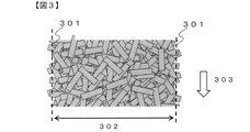
- the short fiber reinforced prepreg sheet width 302 is, as shown in FIG. It is the distance between two straight lines of the short fiber reinforced prepreg sheet end 301 parallel to the first conveyor traveling direction 303 at which the ratio of the portion where the fiber exists and the portion where it does not exist is 50%. indicates
- the short fiber reinforced prepreg sheet width is the distance between two straight lines at the cut off end, and the short fiber reinforced prepreg sheet end is the cut off straight line.
- the width of the short fiber reinforced prepreg sheet is stable when calculated from a section of at least 300 mm in the longitudinal direction of the short fiber reinforced prepreg sheet. Therefore, the width of the short fiber-reinforced prepreg sheet is calculated from a section of at least 300 mm in the longitudinal direction of the short fiber-reinforced prepreg sheet.
- a short fiber reinforced prepreg sheet is cut in a direction perpendicular to the longitudinal direction so that the length is at least 300 mm in the longitudinal direction, and a straight line perpendicular to the cut line is the short fiber reinforced prepreg sheet.
- the arbitrarily set straight line is moved in increments of 0.5 mm in the width direction, and when the short fiber reinforced prepreg sheet is viewed from above, the ratio of locations where chopped fiber bundles are present and where they are not present is 50%.
- the straight line closest to the short fiber reinforced prepreg sheet edge is measured, and the short fiber reinforced prepreg sheet width is obtained by measuring the distance between the straight lines.
- the width 402 of the chopped fiber bundle deposit is defined as the ratio of 50% each of locations where chopped fiber bundles are present and locations where chopped fiber bundles are not present when the chopped fiber bundle deposit is viewed from above, as shown in FIG. is the distance between two straight lines of both ends 401 of the chopped fiber bundle deposit parallel to the first conveyor traveling direction 403 .
- the chopped fiber bundle deposit width is stable when calculated from a section of at least 300 mm in the longitudinal direction of the chopped fiber bundle deposit. Therefore, the width of the chopped fiber bundle deposit is a width calculated from a section of at least 300 mm in the longitudinal direction of the chopped fiber bundle deposit.
- the chopped fiber bundle deposit is cut in a direction perpendicular to the longitudinal direction so that the length is at least 300 mm, and a straight line perpendicular to the cutting line is drawn in the chopped fiber bundle deposit. Set approximately in the center. After that, the arbitrarily set straight line is moved in increments of 0.5 mm in the width direction, and when the short fiber reinforced prepreg sheet is viewed from above, the ratio of locations where chopped fiber bundles are present and where they are not present is 50%. The straight line that is closest to is taken as the chopped fiber bundle deposit, and the distance between these straight lines is measured to be the width of the chopped fiber bundle deposit.
- the width of the chopped fiber bundle deposit can be controlled by spraying in such a spraying area.
- the width of the chopped fiber bundle deposit is set narrower than the desired width of the short fiber reinforced prepreg sheet and set wider than the application width of the matrix resin.
- the short fiber-reinforced prepreg sheet of the present invention has a basis weight variation coefficient CVa of 15% or less for the entire width in the width direction of the short fiber-reinforced prepreg sheet.
- the basis weight variation coefficient CVa of the entire width in the width direction of the short fiber reinforced prepreg sheet is a value defined as follows. Na: Division number (integer) at which the length of one unit is closest to 100 mm when the short fiber reinforced prepreg sheet is equally divided in the sheet width direction.
- a small coefficient of variation in weight per unit area CVa is preferable because it reduces variations in product mass when a molded product is produced using a short fiber reinforced prepreg sheet.
- the CVa is 15% or less, preferably 10% or less, and more preferably 5% or less.
- the basis weight (g/m 2 ) mentioned above is the mass per unit area.
- a method for measuring the basis weight of a short fiber reinforced prepreg sheet measure the mass of a sample cut by placing a cut-out mold of a predetermined size on the short fiber reinforced prepreg sheet, or a sample cut to a predetermined size with a roller cutter. and can be measured by dividing the sample mass by the sample area.
- a method of making CVa 15% or less for example, the input position of the fiber bundle is adjusted in the width direction of the short fiber reinforced prepreg sheet, and the scattering start point of the chopped fiber bundle is adjusted in the width direction of the short fiber reinforced prepreg sheet. and a method of uniformly dispersing chopped fiber bundles using a distributor.
- the short fiber-reinforced prepreg sheet of the present invention is placed on a boundary line 501 set inside (average bundle length of chopped fiber bundles/2) mm from the width direction end 301 of the short fiber-reinforced prepreg sheet.
- a rectangular region having a width direction Lb (mm) and a length direction of 200 mm perpendicular to the first conveyor traveling direction 303 is provided inside the short fiber reinforced prepreg sheet with respect to the boundary so that the long sides of the rectangular region overlap, and the rectangular region
- the basis weight of is 80% or more and 105% or less of the average basis weight of the short fiber reinforced prepreg sheet over the entire width in the width direction.
- Nb The division number (integer) at which the length of one unit is closest to 25 mm when the short fiber reinforced prepreg sheet is equally divided in the sheet width direction between the boundary lines at both ends.
- Lb A value obtained by dividing the length between boundary lines at both ends by Nb.
- the short fiber reinforced prepreg sheet of the present invention has a width direction Lb (mm), a longitudinal A rectangular area with a direction of 200 mm is provided inside the short fiber reinforced prepreg sheet with respect to the boundary line so that the long sides of the rectangular area overlap, and the rectangular area is the average basis weight of the entire width in the width direction of the short fiber reinforced prepreg sheet. 80% or more and 105% or less of The average bundle length of the chopped fiber bundles changes the homogeneity of the chopped fiber bundle deposit, and changes the basis weight of the prepreg sheet ends. Therefore, in the present invention, the fabric weight inside the boundary line set inside (the average bundle length of the chopped fiber bundle/2) mm inside from the width direction end of the short fiber reinforced prepreg sheet is controlled. More specifically, a rectangular region having a width direction Lb (mm) and a longitudinal direction of 200 mm is provided on the boundary line inside the short fiber reinforced prepreg sheet with respect to the boundary line so that the long sides of the rectangular region overlap. It controls the weight.
- the rectangular area has a significantly low basis weight, the rectangular area cannot be used as the product part.
- the basis weight of the rectangular area is significantly higher than the average basis weight of the base material, the edge of the product after winding will swell, causing meandering during roll winding, which may cause wrinkles in the base material or impregnation failure, resulting in dry fiber. There is a possibility that it will be mixed in the molded product and cause defects. Therefore, in the short fiber reinforced prepreg sheet of the present invention, the basis weight of the rectangular region is 80% or more and 105% or less, preferably 90% or more and 105% or less of the average basis weight of the entire width direction of the short fiber reinforced prepreg sheet.
- the rectangular area can be included as the short fiber reinforced prepreg sheet product portion.
- the input position of the fiber bundle is adjusted in the width direction of the short fiber reinforced prepreg sheet, and the scattering start point of the chopped fiber bundle is set in the width direction of the short fiber reinforced prepreg sheet.
- the chopped fiber bundle deposits are scattered at the width direction ends of the chopped fiber bundles.
- a method of adjusting the basis weight of the part, passing through an end basis weight adjusting mechanism, and the like can be mentioned.
- the basis weight of the rectangular area is, for example, a cut-out mold of Lb (mm) in the width direction and 200 mm in the longitudinal direction is placed on the short fiber reinforced prepreg sheet so that the long side of the rectangular area overlaps the boundary line.
- the average basis weight of the entire width in the width direction of the short fiber reinforced prepreg sheet means that the short fiber reinforced prepreg sheet is cut perpendicular to the longitudinal direction so that the length of the short fiber reinforced prepreg sheet is 300 mm or more in the longitudinal direction.
- the mass of the sample obtained by cutting along a straight line that defines the width of the short fiber reinforced prepreg sheet is measured, and the measured mass is calculated as the width direction length (prepreg sheet width) of the sample and the length of the short fiber reinforced prepreg sheet of the sample. It is a value calculated by dividing by the area calculated from the directional length.
- the short fiber reinforced prepreg sheet of the present invention is preferably covered with a release film in at least a 10 mm section outward from the width direction end of the short fiber reinforced prepreg sheet.
- a release film in at least a 10 mm section outward from the width direction end of the short fiber reinforced prepreg sheet.
- a short fiber-reinforced prepreg sheet is provided in which the basis weight and preferably Wf are controlled over the entire width of the short fiber-reinforced prepreg sheet without cutting off the widthwise ends of the short fiber-reinforced prepreg sheet. do.
- Wf (%) of the rectangular region provided inside the short fiber reinforced prepreg sheet with respect to the boundary line is 80 of the average Wf (%) of the total width in the width direction of the short fiber reinforced prepreg sheet. % or more and 120% or less.
- Wf is the mass ratio of reinforcing fibers contained in the short fiber reinforced prepreg sheet. If the Wf is low, the reinforcing effect of the reinforcing fibers is small, and if the Wf is high, impregnation failure may occur, and defects may be formed in the molded product. On the other hand, when Wf is high, the effect of improving the basis weight variation in the width direction of the short fiber reinforced prepreg sheet in the present invention is greatly obtained. Therefore, the Wf of the short fiber reinforced prepreg sheet is preferably 40% or more and 65% or less, more preferably 45% or more and 65% or less, and even more preferably 50% or more and 65% or less.
- Wf As a method for measuring Wf, after collecting a sample from the short fiber reinforced prepreg sheet, for example, it is measured by the combustion method described in the fiber content rate and void content test method for carbon fiber reinforced plastics specified in JIS K 7075-1991. be able to. When the sample size is large, the Wf of the divided sample is measured by dividing it into smaller pieces.
- the average Wf of the full width in the width direction of the short fiber reinforced prepreg sheet is the length of 300 mm or more in the longitudinal direction of the short fiber reinforced prepreg sheet, after cutting the short fiber reinforced prepreg sheet perpendicular to the longitudinal direction. , are values obtained by measuring a sample obtained by cutting along a straight line that defines the width of the short fiber reinforced prepreg sheet by the Wf measurement method described above.
- the Wf of the rectangular region is lower than the average Wf of the short fiber reinforced prepreg sheet, the Wf of the molded product containing the rectangular region decreases, and the strength of the molded product decreases. Can not.
- the Wf (%) of the rectangular region is preferably 80% or more and 120% or less of the average Wf (%) of the short fiber reinforced prepreg sheet, preferably 90% or more and 110% or less, and 95% or more and 105%.
- the input position of the fiber bundle is adjusted in the width direction of the short fiber reinforced prepreg sheet, and the chopped fiber bundle dispersion start point is adjusted.
- chopped fiber bundle deposits A method of adjusting the weight of the width direction end of the chopped fiber bundle that has been dispersed, passing through an end weight adjustment mechanism, and the like.
- Nb rectangular regions each having a side length of Lb (mm) ⁇ 200 mm are arranged next to each other in the width direction so that the long sides are parallel to the boundary lines at both ends. It is preferable that the basis weight in all the rectangular regions when cut from the boundary line is 80% or more and 120% or less of the average basis weight of the entire width in the width direction of the short fiber reinforced prepreg sheet.
- the basis weight in all the rectangular regions is preferably 80% or more and 120% or less, more preferably 90% or more and 110% or less, and 95% or more and 105% of the average basis weight of the short fiber reinforced prepreg sheet in the full width direction. It is more preferably not more than 97% or more and 103% or less is even more preferable.
- the input position of the fiber bundle is adjusted in the width direction of the short fiber reinforced prepreg sheet, and the chopped fiber bundle is scattered at the starting point.
- chopped fiber bundle deposits A method of adjusting the weight of the width direction end of the chopped fiber bundle that has been dispersed, passing through an end weight adjustment mechanism, and the like.
- the short fiber reinforced prepreg sheet of the present invention when two regions having a width Lb (mm) and a length of 200 mm are sequentially cut from the short fiber reinforced prepreg sheet width direction end in the inner direction of the short fiber reinforced prepreg sheet, the short fiber It is preferable that the basis weight of the rectangular area on the end side of the reinforced prepreg sheet is small.
- the input position of the fiber bundle is adjusted in the width direction of the short fiber reinforced prepreg sheet.
- a method of adjusting the scattering start point of the chopped fiber bundles in the width direction of the short fiber reinforced prepreg sheet, or a method of uniformly dispersing the chopped fiber bundles using a distributor and then passing through the step of impregnating with the matrix resin For example, a method of passing through an end weight adjustment mechanism for adjusting the weight of the widthwise end portion of the chopped fiber bundle to which the chopped fiber bundle deposit has been dispersed may be mentioned.
- a region having a width of Lb (mm) and a length of 200 mm is divided in the short fiber reinforced prepreg sheet width direction from the boundary line so that the long side is parallel to the prepreg sheet longitudinal direction.
- the reinforcing fibers are preferably carbon fibers.
- the reinforcing fibers are carbon fibers, it becomes easier to obtain higher strength and lower variations in physical properties.
- the average bundle length of the chopped fiber bundles is preferably 5 mm or more and 100 mm or less.
- the average bundle length of the chopped fiber bundles is 5 mm or more, a reinforcing effect can be easily obtained.
- the average bundle length of the chopped fiber bundle is 100 mm or less, fluidity and shapeability are easily obtained. More preferably, the average bundle length of the chopped fiber bundles is 10 mm or more and 30 mm or less.
- the average basis weight of the entire width in the width direction of the short fiber reinforced prepreg sheet is 1,000 g/m 2 to 4,000 g/m 2 .
- the average basis weight of the short fiber reinforced prepreg sheet over the entire width in the width direction is 1,000 g/m 2 or more, a molded product can be produced efficiently. Further, when the average basis weight is 4,000 g/m 2 or less, better impregnating properties are likely to be obtained.
- the method for producing a short fiber reinforced prepreg sheet of the present invention includes a scattering step of scattering the chopped fiber bundles on a moving body continuously moving in the downstream direction of the process to obtain a chopped fiber bundle deposit, and a chopped fiber bundle deposit. and an impregnation step in which a film coated with a matrix resin is sandwiched from at least one side of and impregnated with the matrix resin, wherein chopped fiber bundle deposits are scattered before passing through the impregnation step.
- the chopped fiber bundle is passed through an end weight adjusting mechanism that adjusts the weight of the widthwise end of the chopped fiber bundle.
- the basis weight of the width direction end of the chopped fiber bundle deposit is adjusted before passing through the step of impregnating with the matrix resin, thereby suppressing the influence of fiber orientation.
- the basis weight in the width direction of the short fiber reinforced prepreg sheet can be controlled while maintaining the uniformity in the width direction of the matrix resin.
- the method for producing a short fiber-reinforced prepreg sheet of the present invention preferably includes a cutting step of cutting reinforcing fibers into chopped fiber bundles before the scattering step.
- the edge area basis weight adjustment mechanism is configured to perform the spreading within a spreading area that is regulated by standing walls at both ends in the width direction of the moving body. After completion of the process, this is a mechanism for widening and leveling the chopped fiber bundles contained in the high basis weight areas formed at both ends in the width direction of the chopped fiber bundle deposit.
- the spraying Chopped fiber bundles that come in contact with the vertical wall that regulates the spread width are deposited just below the vertical wall, and a region with a high basis weight is locally generated. Therefore, in a first preferred aspect of the method for producing a short fiber reinforced prepreg sheet of the present invention, the chopped fiber bundles contained in the high basis weight regions formed at both ends in the width direction of the chopped fiber bundle deposit are placed on the outside in the width direction.
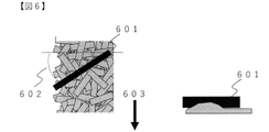
- the edge area basis weight adjustment mechanism is configured to perform the spreading within a spreading area that is regulated by vertical walls at both ends in the width direction of the moving body. After completion of the process, the chopped fiber bundles in the high basis weight areas at both ends are spread outward in the width direction by means of baffle plates or rolls installed downstream of the sprinkling area so as to spread outward in the downstream direction.
- a leveling mechanism is preferred.
- a baffle plate or roll 601 is provided downstream of the chopped fiber bundle scattering area so as to spread outward in the traveling direction 603 of the moving body. Eliminates the area with a locally high basis weight caused by the accumulation of chopped fiber bundles directly under the vertical wall in contact with the vertical wall that regulates the dispersion width during the spraying, and controls the basis weight of the end of the short fiber reinforced prepreg sheet. , it is possible to provide a short fiber reinforced prepreg sheet with a small variation in basis weight in the width direction of the short fiber reinforced prepreg sheet and a small loss width with respect to the product width.
- the material of the baffle plate or roll is not particularly limited, but it is preferable that the surface is smooth and non-static. Such a material can prevent the chopped fiber bundles from adhering to the surface of the baffle plate or the roll upon contact with the chopped fiber bundle deposit.
- the angle formed by the baffle plate or roll and the width direction of the moving body can take a value of 0° or more and less than 90°. , 10° or more and less than 80°.
- the size of the baffle plate or roll is not particularly limited, but it must have a width that can regulate the height of the chopped fiber bundle deposit from the locally high basis weight area immediately below the vertical wall to the area where the chopped fiber bundles are moved when installed. is preferred. With such a width, the chopped fiber bundles in the locally high basis weight area can be continuously moved to the outside of the chopped fiber bundles.
- the lower end of the baffle plate or roll is preferably equal to or higher than the height of the target area, and the height of the area where the basis weight is locally high due to the chopped fiber bundles deposited immediately below the vertical wall preferably less than With such a height, the chopped fiber bundles in the locally high basis weight area can be continuously moved to the outside of the chopped fiber bundles.
- a plurality of baffle plates or rolls may be provided such that the height of the lowermost end gradually decreases in the downstream direction.
- the height of the baffle plate or the diameter of the roll should be sufficiently high with respect to the difference between the height of the locally high basis weight area due to the chopped fiber bundles deposited directly under the vertical wall and the height of the target basis area. It is preferably at least twice the difference.
- the edge area basis weight adjustment mechanism is arranged in an area where both ends in the width direction of the moving body are regulated by vertical walls.
- the vertical wall has a section in which the distance between the vertical walls gradually increases toward the downstream of the manufacturing process.
- the spraying step is carried out within a spraying area regulated by standing walls 701 on both ends in the width direction of the moving body, and the distance between the standing walls gradually increases in the traveling direction 703 of the moving body.
- the section gradually increasing section 702 in FIG. 7
- the portion where the chopped fiber bundle deposit contacts the standing wall surface that regulates the spray width during spraying of both ends of the chopped fiber bundle deposit is the width of the fiber bundle deposit. It is distributed in the direction, and it is possible to prevent the occurrence of locally high basis weight areas at the ends of the chopped fiber bundle.
- the basis weight at the ends of the short fiber-reinforced prepreg sheet is controlled, the fluctuation of the basis weight in the width direction of the short fiber-reinforced prepreg sheet is small, and a short fiber-reinforced prepreg sheet with a small loss width relative to the product width can be provided.
- the length of the gradual increase section in the moving body direction is not particularly limited, but it is preferable that there is no gradual increase area at the downstream end of the moving body in the spraying area, and the spreading area moves at the downstream end of the moving body. It is preferable to have a section in which the upright wall is parallel to the downstream direction of the moving body that is 3% or more of the length in the body direction. Such a structure stabilizes the basis weight of the chopped fiber bundle deposit ends.
- the gradual increase of the distance between vertical walls is not particularly limited, but it is preferably 10% or more and 500% or less of the average bundle length of chopped fiber bundles. By setting it within such a range, the basis weight of the chopped fiber bundle sediment end portion is easily stabilized.
- a third preferred aspect of the method for producing a short fiber reinforced prepreg sheet of the present invention is that the end area basis weight adjustment mechanism performs the spreading within a spreading area in which both ends in the width direction of the moving body are regulated by vertical walls. In the process, an obstacle that prevents the chopped fiber bundle from colliding with the upright wall provided inside the upright wall.
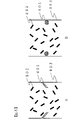
- an obstacle 801 is provided inside the vertical wall 803 to prevent the chopped fiber bundles from colliding with the vertical wall, and at least a portion of the chopped fiber bundles that were to come into contact with the vertical wall are prevented from colliding with the vertical wall. Since the 802 does not come into contact with the obstacle and does not drop directly below the vertical wall, it is possible to suppress the occurrence of a locally high basis weight area at the end of the chopped fiber bundle deposit. As a result, the basis weight of the short fiber reinforced prepreg sheet ends is controlled, the basis weight fluctuation in the width direction of the short fiber reinforced prepreg sheet is small, and a short fiber reinforced prepreg sheet with a small loss width relative to the product width can be provided. .
- the obstacle is not particularly limited as long as it prevents the contact of at least a part of the chopped fiber bundles that were supposed to come into contact with the standing wall, but it is preferable that the surface is smooth and non-static. Also, the obstacle preferably has a slope so that the chopped fiber bundles do not accumulate.
- the shape of the obstacle is not particularly limited.
- a flat plate having an angle such that the piled chopped fiber bundles are dispersed inward in the width direction of the moving body may be used.
- the angled flat plate has a mechanism that changes the amount of protrusion from the wall. By having such a mechanism, it is possible to finely control the basis weight of the width direction end portions.
- Matrix resin Vinyl ester resin (VE) resin (manufactured by Dow Chemical Co., Ltd., "Deraken 790" (registered trademark)) 100 parts by mass, tert-butyl peroxybenzoate (manufactured by NOF Corporation, "Perbutyl Z” (registered trademark) )) 1 part by mass, zinc stearate (manufactured by Sakai Chemical Industry Co., Ltd., SZ-2000) 2 parts by mass, and magnesium oxide (manufactured by Kyowa Chemical Industry Co., Ltd., MgO#40) 4 parts by mass. board.
- VE Vinyl ester resin
- tert-butyl peroxybenzoate manufactured by NOF Corporation, "Perbutyl Z” (registered trademark)
- zinc stearate manufactured by Sakai Chemical Industry Co., Ltd., SZ-2000
- magnesium oxide manufactured by Kyowa Chemical Industry Co., Ltd., MgO#40
- Chopped fiber bundle A continuous carbon fiber strand with 50,000 filaments (manufactured by ZOLTEK, product name: “ZOLTEK (registered trademark)” PX35-50K) was used as the reinforcing fiber bundle.
- the reinforcing fiber bundle was cut at right angles to the longitudinal direction of the reinforcing fiber bundle using a cutting machine so that the chopped fiber bundle had a length of 12.7 mm, thereby obtaining a chopped fiber bundle.
- Example 1 A release film made of polypropylene was unwound from a roll, and a matrix resin was uniformly coated on the upper surface thereof by adjusting the coating amount and coating width using a doctor blade to prepare two resin sheets. At this time, each resin had a coating basis weight of 430 g/m 2 and a coating width of 1490 mm.
- the chopped fiber bundles are continuously pulled out as a moving body while the matrix resin is applied to the upper surface of the first release film. to form a chopped fiber bundle deposit on the moving body.
- the spraying area was a space with a maximum wall-to-wall distance of 1,495 mm, a downstream direction of 1,000 mm, and a height direction of 1,000 mm.
- the scattering start position of the chopped fiber bundles is also one row in the width direction of the mobile body. was an interval. Also, the basis weight of the chopped fiber bundle deposit was 1,140 g/m 2 .
- the chopped fiber bundles are dispersed by a distributor and dropped onto the matrix resin of the first release film to be scattered to form chopped fiber bundle deposits in which the fiber bundles are randomly oriented. formed continuously.
- the disperser had a shape in which 16 wires were arranged at equal intervals on a circle with a diameter of 200 mm centering on the rotating shaft, and the wires were extended across the width direction of the dispersing area.
- the disperser is installed directly below the reinforcing fiber bundle cutter, with the rotating shaft of the disperser horizontal and in the width direction of the moving body. , and the chopped fiber bundles dispersed by rotating clockwise with respect to the rotating shaft of the disperser at a speed of 400 rpm were dispersed in the dispersing area.
- the vertical wall that regulates the spraying width in the width direction of the moving body in the spraying area has a parallel section of 200 mm, a gradually increasing section of 300 mm, and a parallel section of 500 mm from upstream to downstream. Gradation was 25 mm. The gradual increase section of the standing wall was set in this way, and the chopped fiber bundles deposited directly under the standing wall in contact with the standing wall were dispersed in the width direction of the moving body.
- the width of the chopped fiber bundle deposit obtained as described above was 1,495 mm.
- the chopped fiber bundle deposit thus obtained did not produce a high basis weight area due to the chopped fiber bundles deposited directly under the vertical wall surface in contact with the vertical wall surface.
- the second release film is placed on the upper surface of the chopped fiber bundle deposit with the matrix resin-coated surface of the second release film being the vertical lower surface, and the chopped fiber bundle deposit is separated from the upper and lower surfaces by the first release film and the second release film.
- the chopped fiber bundle deposit was impregnated with a matrix resin using a compaction roll, wound on a paper tube, and thickened at 40° C. for 24 hours to obtain SMC.
- the resulting SMC width was 1,500 mm.
- the obtained SMC was cut in the width direction of the SMC so that it was 300 mm in the longitudinal direction, and the average basis weight of the entire width in the width direction and the average Wf of the entire width in the width direction of the SMC were calculated. /m 2 and the average Wf was 57%.
- a boundary line was set 6.35 mm inward from the width direction end of the obtained SMC, and the long side of the rectangular area of 24.79 mm in the SMC width direction and 200 mm in the longitudinal direction overlapped with the boundary line.
- the basis weight and Wf of the rectangular area were calculated on the inside of the short fiber reinforced prepreg sheet with respect to the boundary line, the basis weight was 1,920 g/m 2 , which was 96% of the average basis weight over the entire width of the SMC.
- Wf was 56%, which was 98% of the average Wf of the full width in the width direction of the SMC.
- Table 1 shows the presence or absence of standing walls, the types of end adjustment mechanisms, evaluation results, etc. of Examples 1 to 4 and Comparative Examples 1 and 2.
- Example 2 A release film made of polypropylene was unwound from a roll, and a matrix resin was uniformly coated on the upper surface thereof by adjusting the coating amount and coating width using a doctor blade to prepare two resin sheets. At this time, each resin had a coating basis weight of 430 g/m 2 and a coating width of 1,490 mm.
- the chopped fiber bundles are continuously pulled out as a moving body while the matrix resin is applied to the upper surface of the first release film. to form a chopped fiber bundle deposit on the moving body.
- the scattering start positions of the chopped fiber bundles are also arranged in one row in the width direction of the moving body. was an interval. Also, the basis weight of the chopped fiber bundle deposit was 1,140 g/m 2 .
- the chopped fiber bundles are dispersed by a distributor and dropped onto the matrix resin of the first release film to be scattered to form chopped fiber bundle deposits in which the fiber bundles are randomly oriented. formed continuously.
- the disperser had a shape in which 16 wires were arranged at equal intervals on a circle with a diameter of 200 mm centering on the rotating shaft, and the wires were extended across the width direction of the dispersing area.
- the disperser is installed directly below the reinforcing fiber bundle cutter, with the rotation axis of the disperser horizontal and in the width direction of the moving body. , and the chopped fiber bundles dispersed by rotating clockwise with respect to the rotating shaft of the disperser at a speed of 400 rpm were dispersed in the dispersing area.
- the spraying area was a space with a distance between vertical walls of 1,495 mm, a downstream direction of 1,000 mm, and a height direction of 1,000 mm.
- the standing walls that regulate the spraying width in the width direction of the moving body in the spraying area did not have a section parallel to the downstream direction of the moving body and the distance between the standing walls gradually increased.
- the chopped fiber bundle deposit obtained had a high basis weight region at the end of the chopped fiber bundle deposit due to the chopped fiber bundles deposited directly under the vertical wall surface in contact with the vertical wall surface.
- the height of the high basis weight area of the chopped fiber bundle deposit was 20 mm, and the height of the other areas was 15 mm.
- the baffle plate was a flat stainless steel plate having a thickness of 2 mm, a width of 150 mm, and a height of 70 mm, and was attached so that the lower end in the height direction had a height of 16 mm.
- the angle formed by the baffle plate or roll and the width direction of the moving body was 45°.
- the center position of the baffle in the width direction and the center of the standing wall were aligned in the downstream direction of the moving body.
- the chopped fiber bundles contained in the high basis weight area of the chopped fiber bundle deposit were moved to the edge side of the chopped fiber bundle deposit by the baffle plate, and the high basis weight area became equivalent to the normal basis weight.
- the width of the chopped fiber bundle deposit obtained as described above was 1495 mm.
- the second release film is placed on the upper surface of the chopped fiber bundle deposit with the matrix resin-coated surface of the second release film being the vertical lower surface, and the chopped fiber bundle deposit is separated from the upper and lower surfaces by the first release film and the second release film.
- the chopped fiber bundle deposit was impregnated with a matrix resin using a compaction roll, wound on a paper tube, and thickened at 40° C. for 24 hours to obtain SMC.
- the SMC width obtained was 1500 mm.
- the obtained SMC was cut in the width direction of the SMC so that it was 300 mm in the longitudinal direction, and the average basis weight of the entire width in the width direction and the average Wf of the entire width in the width direction of the SMC were calculated. /m 2 and the average Wf was 57%.
- a boundary line was set 6.35 mm inward from the width direction end of the obtained SMC, and the boundary was set so that the long side of a rectangular area of 24.79 mm in the width direction of the SMC and 200 mm in the longitudinal direction overlaps the boundary line.
- the basis weight and Wf of the rectangular area were calculated by providing the short fiber reinforced prepreg sheet inside the line, the basis weight was 1,912 g/m 2 , which was 96% of the average basis weight over the entire width of the SMC.
- Wf was 56%, which was 98% of the average Wf of the full width in the width direction of the SMC.
- Example 3 A release film made of polypropylene was unwound from a roll, and a matrix resin was uniformly coated on the upper surface thereof by adjusting the coating amount and coating width using a doctor blade to prepare two resin sheets. At this time, each resin had a coating basis weight of 430 g/m 2 and a coating width of 1,490 mm.
- the chopped fiber bundles are continuously pulled out as a moving body while the matrix resin is applied to the upper surface of the first release film. to form a chopped fiber bundle deposit on the moving body.
- the spraying area was a space with a distance between vertical walls of 1,495 mm, a downstream direction of 1,000 mm, and a height direction of 1,000 mm.
- the scattering start positions of the chopped fiber bundles are also arranged in one row in the width direction of the moving body. was an interval. Also, the basis weight of the chopped fiber bundle deposit was 1,140 g/m 2 .
- the chopped fiber bundles are dispersed by a distributor and dropped onto the matrix resin of the first release film to be scattered to form chopped fiber bundle deposits in which the fiber bundles are randomly oriented. formed continuously.
- the disperser had a shape in which 16 wires were arranged at equal intervals on a circle with a diameter of 200 mm centering on the rotating shaft, and the wires were extended across the width direction of the dispersing area.
- the disperser is installed directly under the reinforcing fiber bundle cutting machine, with the rotation axis of the disperser horizontal and in the width direction of the moving body.
- the scattered chopped fiber bundles were dispersed in the scattering area by rotating the rotating shaft of the disperser clockwise at a speed of 400 rpm.
- the standing walls that regulate the spray width in the width direction of the moving body in the spraying area were parallel to the downstream direction of the moving body and did not have a section where the distance between the standing walls gradually increased.
- the cylinder had a diameter of 20 mm, a projection length of 100 mm, and an angle between the cylinder and the vertically downward direction of 60°.
- the width of the chopped fiber bundle deposit obtained as described above was 1,495 mm.
- the chopped fiber bundle deposit thus obtained did not produce a high basis weight area due to the chopped fiber bundles deposited directly under the vertical wall surface in contact with the vertical wall surface.
- the second release film is placed on the upper surface of the chopped fiber bundle deposit with the matrix resin-coated surface of the second release film being the vertical lower surface, and the chopped fiber bundle deposit is separated from the upper and lower surfaces by the first release film and the second release film.
- the chopped fiber bundle deposit was impregnated with a matrix resin using a compaction roll, wound on a paper tube, and thickened at 40° C. for 24 hours to obtain SMC.
- the resulting SMC width was 1,500 mm.
- the obtained SMC was cut in the width direction of the SMC so that it was 300 mm in the longitudinal direction, and the average basis weight of the entire width in the width direction and the average Wf of the entire width in the width direction of the SMC were calculated. /m 2 and the average Wf was 57%.
- a boundary line was set 6.35 mm inward from the width direction end of the obtained SMC, and the boundary was set so that the long side of a rectangular area of 24.79 mm in the width direction of the SMC and 200 mm in the longitudinal direction overlaps the boundary line.
- the basis weight and Wf of the rectangular area were calculated by providing the short fiber reinforced prepreg sheet inside the line, the basis weight was 1,940 g/m 2 , which was 97% of the average basis weight over the entire width of the SMC.
- Wf was 56%, which was 98% of the average Wf of the full width in the width direction of the SMC.
- Example 4 A release film made of polypropylene was unwound from a roll, and a matrix resin was uniformly coated on the upper surface thereof by adjusting the coating amount and the coating width using a doctor blade to prepare two resin sheets. At this time, each resin had a coating basis weight of 430 g/m 2 and a coating width of 1,490 mm.
- the chopped fiber bundles are continuously pulled out as a moving body while the matrix resin is applied to the upper surface of the first release film. to form a chopped fiber bundle deposit on the moving body.
- the scattering start positions of the chopped fiber bundles are also arranged in one row in the width direction of the moving body. was an interval. Also, the basis weight of the chopped fiber bundle deposit was 1,140 g/m 2 .
- the chopped fiber bundles are dispersed by a distributor and dropped onto the matrix resin of the first release film to be scattered to form chopped fiber bundle deposits in which the fiber bundles are randomly oriented. formed continuously.
- the disperser had a shape in which 16 wires were arranged at equal intervals on a circle with a diameter of 200 mm centering on the rotating shaft, and the wires were extended across the width direction of the dispersing area.
- the disperser is installed directly below the reinforcing fiber bundle cutter, with the rotation axis of the disperser horizontal and in the width direction of the moving body. , and the chopped fiber bundles dispersed by rotating clockwise with respect to the rotating shaft of the disperser at a speed of 400 rpm were dispersed in the dispersing area.
- the spraying area was a space with a distance between vertical walls of 1,495 mm, a downstream direction of 1,000 mm, and a height direction of 1,000 mm.
- the standing walls that regulate the spraying width in the width direction of the moving body in the spraying area did not have a section parallel to the downstream direction of the moving body and the distance between the standing walls gradually increased.
- four flat plates with a width of 100 mm and a length of 100 mm were placed downward from the vertical wall at an angle of 60°. It was installed so as to stick out.
- the width of the chopped fiber bundle deposit obtained as described above was 1,495 mm.
- the chopped fiber bundle deposit thus obtained did not produce a high basis weight area due to the chopped fiber bundles deposited directly under the vertical wall surface in contact with the vertical wall surface.
- the second release film is placed on the upper surface of the chopped fiber bundle deposit with the matrix resin-coated surface of the second release film being the vertical lower surface, and the chopped fiber bundle deposit is separated from the upper and lower surfaces by the first release film and the second release film.
- the chopped fiber bundle deposit was impregnated with a matrix resin using a compaction roll, wound on a paper tube, and thickened at 40° C. for 24 hours to obtain SMC.
- the resulting SMC width was 1,500 mm.
- the obtained SMC was cut in the width direction of the SMC so that it was 300 mm in the longitudinal direction, and the average basis weight of the entire width in the width direction and the average Wf of the entire width in the width direction of the SMC were calculated. /m 2 and the average Wf was 57%.
- a boundary line was set 6.35 mm inward from the width direction end of the obtained SMC, and the long side of the rectangular area of 24.79 mm in the SMC width direction and 200 mm in the longitudinal direction overlapped with the boundary line.
- the basis weight and Wf of the rectangular area were calculated on the inner side of the short fiber reinforced prepreg sheet with respect to the boundary line, the basis weight was 2,010 g/m 2 , which was 101% of the average basis weight over the entire width of the SMC.
- Wf was 57%, which was 100% of the average Wf of the full width in the width direction of the SMC.
- the average basis weight was 98% or more and 103% or less in all the rectangular regions.
- Example 1 An SMC was produced in the same manner as in Example 1, except that the chopped fiber bundles were spread in a spreading area in which the vertical wall that regulates the spread width in the width direction of the moving body is parallel to the downstream direction of the moving body. .
- the chopped fiber bundle deposit obtained had a high basis weight region at the end of the chopped fiber bundle deposit due to the chopped fiber bundles deposited directly under the vertical wall surface in contact with the vertical wall surface.
- the height of the high basis weight area of the chopped fiber bundle deposit was 20 mm, and the height of the other areas was 15 mm.
- the obtained SMC was cut in the width direction of the SMC so that it was 300 mm in the longitudinal direction, and the average basis weight of the entire width in the width direction and the average Wf of the entire width in the width direction of the SMC were calculated. /m 2 and the average Wf was 57%.
- a boundary line was set 6.35 mm inward from the width direction end of the obtained SMC, and the boundary was set so that the long side of a rectangular area of 24.79 mm in the width direction of the SMC and 200 mm in the longitudinal direction overlaps the boundary line.
- the basis weight was 2,120 g/m 2 , which was 106% of the average basis weight over the entire width of the SMC.
- Wf was 60%, which was 105% of the average Wf of the full width in the width direction of the SMC.
- the average basis weight was 80% or more and 120% or less in all the rectangular regions.
- the basis weight of the endmost portion is , raised relative to its one inner region.
- the obtained SMC was cut in the width direction of the SMC so that it was 300 mm in the longitudinal direction, and the average basis weight of the entire width in the width direction and the average Wf of the entire width in the width direction of the SMC were calculated. /m 2 and the average Wf was 57%.
- a boundary line was set 6.35 mm inward from the width direction end of the obtained SMC, and the boundary was set so that the long side of a rectangular area of 24.79 mm in the width direction of the SMC and 200 mm in the longitudinal direction overlaps the boundary line.
- the basis weight and Wf of the rectangular area were calculated by providing the short fiber reinforced prepreg sheet inside the line, the basis weight was 1,560 g/m 2 , which was 78% of the average basis weight over the entire width of the SMC.
- Wf was 45%, which was 79% of the average Wf of the full width in the width direction of the SMC.
- the average basis weight was 80% or more and 120% or less in all the rectangular regions.
- the basis weight of the endmost portion is , raised relative to its one inner region.
- a molded product using the short fiber reinforced prepreg sheet of the present invention can be suitably used for automobiles and other transportation equipment.
Landscapes
- Engineering & Computer Science (AREA)
- Chemical & Material Sciences (AREA)
- Textile Engineering (AREA)
- Mechanical Engineering (AREA)
- Composite Materials (AREA)
- Inorganic Chemistry (AREA)
- Chemical Kinetics & Catalysis (AREA)
- Materials Engineering (AREA)
- General Chemical & Material Sciences (AREA)
- Dispersion Chemistry (AREA)
- Manufacturing & Machinery (AREA)
- Health & Medical Sciences (AREA)
- Medicinal Chemistry (AREA)
- Polymers & Plastics (AREA)
- Organic Chemistry (AREA)
- Reinforced Plastic Materials (AREA)
Priority Applications (2)
| Application Number | Priority Date | Filing Date | Title |
|---|---|---|---|
| JP2022523194A JPWO2022202981A1 (https=) | 2021-03-25 | 2022-03-24 | |
| EP22775762.2A EP4316765A4 (en) | 2021-03-25 | 2022-03-24 | Short fiber reinforced prepreg film and method for producing a short fiber reinforced prepreg film |
Applications Claiming Priority (2)
| Application Number | Priority Date | Filing Date | Title |
|---|---|---|---|
| JP2021051671 | 2021-03-25 | ||
| JP2021-051671 | 2021-03-25 |
Publications (1)
| Publication Number | Publication Date |
|---|---|
| WO2022202981A1 true WO2022202981A1 (ja) | 2022-09-29 |
Family
ID=83397355
Family Applications (1)
| Application Number | Title | Priority Date | Filing Date |
|---|---|---|---|
| PCT/JP2022/013893 Ceased WO2022202981A1 (ja) | 2021-03-25 | 2022-03-24 | 短繊維強化プリプレグシート、および短繊維強化プリプレグシートの製造方法 |
Country Status (3)
| Country | Link |
|---|---|
| EP (1) | EP4316765A4 (https=) |
| JP (1) | JPWO2022202981A1 (https=) |
| WO (1) | WO2022202981A1 (https=) |
Citations (8)
| Publication number | Priority date | Publication date | Assignee | Title |
|---|---|---|---|---|
| JP2010235779A (ja) * | 2009-03-31 | 2010-10-21 | Toray Ind Inc | プリプレグ、プリフォームおよび成形品 |
| JP2013028062A (ja) * | 2011-07-28 | 2013-02-07 | Mitsubishi Rayon Co Ltd | 複合材料の製造装置および製造方法 |
| JP2013202969A (ja) * | 2012-03-29 | 2013-10-07 | Mitsubishi Rayon Co Ltd | 繊維強化熱可塑性樹脂ランダムシート及びその製造方法 |
| JP2014210991A (ja) | 2013-04-18 | 2014-11-13 | 帝人株式会社 | 強化繊維マットおよび強化繊維マットの製造方法 |
| JP5822033B2 (ja) | 2013-10-22 | 2015-11-24 | 三菱レイヨン株式会社 | プリプレグの製造方法 |
| CN207736777U (zh) * | 2018-01-11 | 2018-08-17 | 常州日新模塑科技有限公司 | 一种smc片材机的铺料装置 |
| JP2019039124A (ja) | 2017-08-23 | 2019-03-14 | 東レ株式会社 | チョップド繊維束マット |
| WO2020090877A1 (ja) * | 2018-10-31 | 2020-05-07 | 東レ株式会社 | 繊維強化樹脂成形材料およびその成形品 |
Family Cites Families (1)
| Publication number | Priority date | Publication date | Assignee | Title |
|---|---|---|---|---|
| JP2010023577A (ja) * | 2008-07-16 | 2010-02-04 | Bridgestone Corp | タイヤ及びその製造方法 |
-
2022
- 2022-03-24 WO PCT/JP2022/013893 patent/WO2022202981A1/ja not_active Ceased
- 2022-03-24 JP JP2022523194A patent/JPWO2022202981A1/ja active Pending
- 2022-03-24 EP EP22775762.2A patent/EP4316765A4/en active Pending
Patent Citations (8)
| Publication number | Priority date | Publication date | Assignee | Title |
|---|---|---|---|---|
| JP2010235779A (ja) * | 2009-03-31 | 2010-10-21 | Toray Ind Inc | プリプレグ、プリフォームおよび成形品 |
| JP2013028062A (ja) * | 2011-07-28 | 2013-02-07 | Mitsubishi Rayon Co Ltd | 複合材料の製造装置および製造方法 |
| JP2013202969A (ja) * | 2012-03-29 | 2013-10-07 | Mitsubishi Rayon Co Ltd | 繊維強化熱可塑性樹脂ランダムシート及びその製造方法 |
| JP2014210991A (ja) | 2013-04-18 | 2014-11-13 | 帝人株式会社 | 強化繊維マットおよび強化繊維マットの製造方法 |
| JP5822033B2 (ja) | 2013-10-22 | 2015-11-24 | 三菱レイヨン株式会社 | プリプレグの製造方法 |
| JP2019039124A (ja) | 2017-08-23 | 2019-03-14 | 東レ株式会社 | チョップド繊維束マット |
| CN207736777U (zh) * | 2018-01-11 | 2018-08-17 | 常州日新模塑科技有限公司 | 一种smc片材机的铺料装置 |
| WO2020090877A1 (ja) * | 2018-10-31 | 2020-05-07 | 東レ株式会社 | 繊維強化樹脂成形材料およびその成形品 |
Non-Patent Citations (1)
| Title |
|---|
| See also references of EP4316765A4 |
Also Published As
| Publication number | Publication date |
|---|---|
| EP4316765A1 (en) | 2024-02-07 |
| EP4316765A4 (en) | 2025-03-19 |
| JPWO2022202981A1 (https=) | 2022-09-29 |
Similar Documents
| Publication | Publication Date | Title |
|---|---|---|
| US9850368B2 (en) | Carbon fiber composite material | |
| JP5996320B2 (ja) | ランダムマットの製造方法 | |
| US20010032696A1 (en) | Process and device for the manufacture of a composite material | |
| KR102048276B1 (ko) | Smc 제조방법 및 그 제조장치 | |
| CN106163756A (zh) | 在流化床中生产预浸渍有热塑性聚合物的纤维质材料的方法 | |
| JP7400807B2 (ja) | 繊維強化樹脂成形材料成形品およびその製造方法 | |
| CN109312503A (zh) | 部分分纤纤维束及其制造方法、以及使用了部分分纤纤维束的纤维增强树脂成型材料及其制造方法 | |
| US20160053432A1 (en) | Carbon fiber nonwoven fabric | |
| CN109312502A (zh) | 部分分纤纤维束及其制造方法、以及使用了部分分纤纤维束的纤维增强树脂成型材料及其制造方法 | |
| KR20180113992A (ko) | 불연속 섬유 강화 복합 재료 | |
| CN112955294B (zh) | 纤维增强树脂成型材料及其成型品 | |
| CN115298006B (zh) | Smc的制造方法 | |
| TW201800217A (zh) | 不連續纖維強化複合材料 | |
| EP3527344B9 (en) | Random mat and production method therefor, and fiber-reinforced resin molded material using random mat | |
| JP7622499B2 (ja) | 短繊維強化プリプレグシートの製造方法 | |
| CN109312505B (zh) | 部分分纤纤维束及其制造方法、以及纤维增强树脂成型材料及其制造方法 | |
| US20150258762A1 (en) | Method of Producing Isotropic Random Mat for Forming Thermoplastic Composite Material | |
| WO2022202981A1 (ja) | 短繊維強化プリプレグシート、および短繊維強化プリプレグシートの製造方法 | |
| KR20080030611A (ko) | 중합체/습식 절단 스트랜드 유리 섬유 매트 및 이를형성하는 방법 | |
| US20050118390A1 (en) | Continuous strand mats, methods of producing continuous strand mats, and systems for producing continuous strand mats | |
| JP6540005B2 (ja) | スタンパブル基材の製造方法 | |
| US20150292146A1 (en) | Stampable sheet | |
| JP3772644B2 (ja) | ガラスチョップドストランドマット及びその製造方法 | |
| JPH038857A (ja) | 無機繊維不織布 | |
| CN120112400A (zh) | 片状预浸料的制造方法、纤维原料的供给方法以及片状预浸料 |
Legal Events
| Date | Code | Title | Description |
|---|---|---|---|
| ENP | Entry into the national phase |
Ref document number: 2022523194 Country of ref document: JP Kind code of ref document: A |
|
| 121 | Ep: the epo has been informed by wipo that ep was designated in this application |
Ref document number: 22775762 Country of ref document: EP Kind code of ref document: A1 |
|
| WWE | Wipo information: entry into national phase |
Ref document number: 2022775762 Country of ref document: EP |
|
| NENP | Non-entry into the national phase |
Ref country code: DE |
|
| ENP | Entry into the national phase |
Ref document number: 2022775762 Country of ref document: EP Effective date: 20231025 |