WO2022202218A1 - ウエルアレイと粒子とを用いた生体物質検出方法、ウエルアレイ及び検出装置 - Google Patents
ウエルアレイと粒子とを用いた生体物質検出方法、ウエルアレイ及び検出装置 Download PDFInfo
- Publication number
- WO2022202218A1 WO2022202218A1 PCT/JP2022/009369 JP2022009369W WO2022202218A1 WO 2022202218 A1 WO2022202218 A1 WO 2022202218A1 JP 2022009369 W JP2022009369 W JP 2022009369W WO 2022202218 A1 WO2022202218 A1 WO 2022202218A1
- Authority
- WO
- WIPO (PCT)
- Prior art keywords
- particles
- well
- pixels
- biological substance
- detection
- Prior art date
Links
- 239000002245 particle Substances 0.000 title claims abstract description 230
- 238000001514 detection method Methods 0.000 title claims abstract description 122
- 239000000126 substance Substances 0.000 title claims abstract description 107
- 238000003384 imaging method Methods 0.000 claims abstract description 50
- 239000012085 test solution Substances 0.000 claims abstract description 42
- 238000004040 coloring Methods 0.000 claims abstract description 23
- 239000007788 liquid Substances 0.000 claims description 46
- 238000012360 testing method Methods 0.000 claims description 41
- 238000011161 development Methods 0.000 claims description 29
- 239000006249 magnetic particle Substances 0.000 claims description 22
- 238000000034 method Methods 0.000 claims description 22
- 230000004308 accommodation Effects 0.000 claims description 13
- 238000002360 preparation method Methods 0.000 claims description 12
- 239000000758 substrate Substances 0.000 claims description 12
- 238000006243 chemical reaction Methods 0.000 claims description 11
- 239000003086 colorant Substances 0.000 claims description 11
- 238000000638 solvent extraction Methods 0.000 claims description 2
- 230000035945 sensitivity Effects 0.000 abstract description 9
- 239000000243 solution Substances 0.000 abstract description 3
- 241000700605 Viruses Species 0.000 description 22
- 239000012620 biological material Substances 0.000 description 18
- 102000004169 proteins and genes Human genes 0.000 description 18
- 108090000623 proteins and genes Proteins 0.000 description 18
- 230000035484 reaction time Effects 0.000 description 18
- 239000011324 bead Substances 0.000 description 16
- 241000712461 unidentified influenza virus Species 0.000 description 15
- 238000006911 enzymatic reaction Methods 0.000 description 11
- 238000004519 manufacturing process Methods 0.000 description 10
- 108090000790 Enzymes Proteins 0.000 description 9
- 102000004190 Enzymes Human genes 0.000 description 9
- 230000001717 pathogenic effect Effects 0.000 description 9
- 238000002965 ELISA Methods 0.000 description 8
- 238000010586 diagram Methods 0.000 description 8
- 239000000523 sample Substances 0.000 description 8
- 230000015572 biosynthetic process Effects 0.000 description 7
- 239000003153 chemical reaction reagent Substances 0.000 description 7
- 238000005755 formation reaction Methods 0.000 description 7
- HSHNITRMYYLLCV-UHFFFAOYSA-N 4-methylumbelliferone Chemical compound C1=C(O)C=CC2=C1OC(=O)C=C2C HSHNITRMYYLLCV-UHFFFAOYSA-N 0.000 description 6
- 238000004020 luminiscence type Methods 0.000 description 6
- 239000000463 material Substances 0.000 description 6
- 238000002372 labelling Methods 0.000 description 5
- 238000001000 micrograph Methods 0.000 description 5
- 239000000427 antigen Substances 0.000 description 4
- 102000036639 antigens Human genes 0.000 description 4
- 108091007433 antigens Proteins 0.000 description 4
- 239000011521 glass Substances 0.000 description 4
- 238000012545 processing Methods 0.000 description 4
- 239000012488 sample solution Substances 0.000 description 4
- 239000004033 plastic Substances 0.000 description 3
- 210000003296 saliva Anatomy 0.000 description 3
- 238000004904 shortening Methods 0.000 description 3
- 239000012798 spherical particle Substances 0.000 description 3
- PSGQCCSGKGJLRL-UHFFFAOYSA-N 4-methyl-2h-chromen-2-one Chemical group C1=CC=CC2=C1OC(=O)C=C2C PSGQCCSGKGJLRL-UHFFFAOYSA-N 0.000 description 2
- 241000711573 Coronaviridae Species 0.000 description 2
- 102000005936 beta-Galactosidase Human genes 0.000 description 2
- 108010005774 beta-Galactosidase Proteins 0.000 description 2
- 239000000919 ceramic Substances 0.000 description 2
- 239000003795 chemical substances by application Substances 0.000 description 2
- 230000007423 decrease Effects 0.000 description 2
- 239000012530 fluid Substances 0.000 description 2
- 239000007850 fluorescent dye Substances 0.000 description 2
- 238000001459 lithography Methods 0.000 description 2
- 239000011159 matrix material Substances 0.000 description 2
- 238000005259 measurement Methods 0.000 description 2
- 239000002923 metal particle Substances 0.000 description 2
- 238000001020 plasma etching Methods 0.000 description 2
- 238000011002 quantification Methods 0.000 description 2
- 229910052710 silicon Inorganic materials 0.000 description 2
- 239000010703 silicon Substances 0.000 description 2
- 241000894006 Bacteria Species 0.000 description 1
- IGXWBGJHJZYPQS-SSDOTTSWSA-N D-Luciferin Chemical compound OC(=O)[C@H]1CSC(C=2SC3=CC=C(O)C=C3N=2)=N1 IGXWBGJHJZYPQS-SSDOTTSWSA-N 0.000 description 1
- CYCGRDQQIOGCKX-UHFFFAOYSA-N Dehydro-luciferin Natural products OC(=O)C1=CSC(C=2SC3=CC(O)=CC=C3N=2)=N1 CYCGRDQQIOGCKX-UHFFFAOYSA-N 0.000 description 1
- BJGNCJDXODQBOB-UHFFFAOYSA-N Fivefly Luciferin Natural products OC(=O)C1CSC(C=2SC3=CC(O)=CC=C3N=2)=N1 BJGNCJDXODQBOB-UHFFFAOYSA-N 0.000 description 1
- YCKRFDGAMUMZLT-UHFFFAOYSA-N Fluorine atom Chemical compound [F] YCKRFDGAMUMZLT-UHFFFAOYSA-N 0.000 description 1
- 108060001084 Luciferase Proteins 0.000 description 1
- 239000005089 Luciferase Substances 0.000 description 1
- DDWFXDSYGUXRAY-UHFFFAOYSA-N Luciferin Natural products CCc1c(C)c(CC2NC(=O)C(=C2C=C)C)[nH]c1Cc3[nH]c4C(=C5/NC(CC(=O)O)C(C)C5CC(=O)O)CC(=O)c4c3C DDWFXDSYGUXRAY-UHFFFAOYSA-N 0.000 description 1
- 108010067390 Viral Proteins Proteins 0.000 description 1
- 238000004220 aggregation Methods 0.000 description 1
- 230000002776 aggregation Effects 0.000 description 1
- 239000008280 blood Substances 0.000 description 1
- 210000004369 blood Anatomy 0.000 description 1
- 239000007853 buffer solution Substances 0.000 description 1
- 150000001875 compounds Chemical class 0.000 description 1
- 239000006059 cover glass Substances 0.000 description 1
- 238000013461 design Methods 0.000 description 1
- 238000007865 diluting Methods 0.000 description 1
- 238000010494 dissociation reaction Methods 0.000 description 1
- 230000005593 dissociations Effects 0.000 description 1
- 238000009826 distribution Methods 0.000 description 1
- 238000001312 dry etching Methods 0.000 description 1
- 230000000694 effects Effects 0.000 description 1
- 238000005516 engineering process Methods 0.000 description 1
- 230000007613 environmental effect Effects 0.000 description 1
- 230000005284 excitation Effects 0.000 description 1
- 238000002474 experimental method Methods 0.000 description 1
- GNBHRKFJIUUOQI-UHFFFAOYSA-N fluorescein Chemical compound O1C(=O)C2=CC=CC=C2C21C1=CC=C(O)C=C1OC1=CC(O)=CC=C21 GNBHRKFJIUUOQI-UHFFFAOYSA-N 0.000 description 1
- 229910052731 fluorine Inorganic materials 0.000 description 1
- 239000011737 fluorine Substances 0.000 description 1
- 238000005194 fractionation Methods 0.000 description 1
- 230000005484 gravity Effects 0.000 description 1
- 239000000185 hemagglutinin Substances 0.000 description 1
- 238000009396 hybridization Methods 0.000 description 1
- 230000002209 hydrophobic effect Effects 0.000 description 1
- 238000003018 immunoassay Methods 0.000 description 1
- 208000015181 infectious disease Diseases 0.000 description 1
- 238000001746 injection moulding Methods 0.000 description 1
- 238000002032 lab-on-a-chip Methods 0.000 description 1
- 239000003921 oil Substances 0.000 description 1
- 238000000879 optical micrograph Methods 0.000 description 1
- 238000000206 photolithography Methods 0.000 description 1
- 125000002924 primary amino group Chemical group [H]N([H])* 0.000 description 1
- 238000003672 processing method Methods 0.000 description 1
- 230000002035 prolonged effect Effects 0.000 description 1
- 238000002331 protein detection Methods 0.000 description 1
- 238000011160 research Methods 0.000 description 1
- 239000011347 resin Substances 0.000 description 1
- 229920005989 resin Polymers 0.000 description 1
- HSSLDCABUXLXKM-UHFFFAOYSA-N resorufin Chemical compound C1=CC(=O)C=C2OC3=CC(O)=CC=C3N=C21 HSSLDCABUXLXKM-UHFFFAOYSA-N 0.000 description 1
- 230000004043 responsiveness Effects 0.000 description 1
- PYWVYCXTNDRMGF-UHFFFAOYSA-N rhodamine B Chemical class [Cl-].C=12C=CC(=[N+](CC)CC)C=C2OC2=CC(N(CC)CC)=CC=C2C=1C1=CC=CC=C1C(O)=O PYWVYCXTNDRMGF-UHFFFAOYSA-N 0.000 description 1
- 238000004062 sedimentation Methods 0.000 description 1
- 239000004065 semiconductor Substances 0.000 description 1
- 239000002904 solvent Substances 0.000 description 1
- 230000003595 spectral effect Effects 0.000 description 1
- 238000001228 spectrum Methods 0.000 description 1
- 238000003756 stirring Methods 0.000 description 1
- 230000008685 targeting Effects 0.000 description 1
- 210000002700 urine Anatomy 0.000 description 1
- XLYOFNOQVPJJNP-UHFFFAOYSA-N water Substances O XLYOFNOQVPJJNP-UHFFFAOYSA-N 0.000 description 1
Images


Classifications
-
- G—PHYSICS
- G01—MEASURING; TESTING
- G01N—INVESTIGATING OR ANALYSING MATERIALS BY DETERMINING THEIR CHEMICAL OR PHYSICAL PROPERTIES
- G01N33/00—Investigating or analysing materials by specific methods not covered by groups G01N1/00 - G01N31/00
- G01N33/48—Biological material, e.g. blood, urine; Haemocytometers
- G01N33/50—Chemical analysis of biological material, e.g. blood, urine; Testing involving biospecific ligand binding methods; Immunological testing
- G01N33/53—Immunoassay; Biospecific binding assay; Materials therefor
- G01N33/569—Immunoassay; Biospecific binding assay; Materials therefor for microorganisms, e.g. protozoa, bacteria, viruses
- G01N33/56983—Viruses
-
- G—PHYSICS
- G01—MEASURING; TESTING
- G01N—INVESTIGATING OR ANALYSING MATERIALS BY DETERMINING THEIR CHEMICAL OR PHYSICAL PROPERTIES
- G01N33/00—Investigating or analysing materials by specific methods not covered by groups G01N1/00 - G01N31/00
- G01N33/48—Biological material, e.g. blood, urine; Haemocytometers
- G01N33/483—Physical analysis of biological material
- G01N33/487—Physical analysis of biological material of liquid biological material
-
- B—PERFORMING OPERATIONS; TRANSPORTING
- B01—PHYSICAL OR CHEMICAL PROCESSES OR APPARATUS IN GENERAL
- B01L—CHEMICAL OR PHYSICAL LABORATORY APPARATUS FOR GENERAL USE
- B01L3/00—Containers or dishes for laboratory use, e.g. laboratory glassware; Droppers
- B01L3/50—Containers for the purpose of retaining a material to be analysed, e.g. test tubes
- B01L3/508—Containers for the purpose of retaining a material to be analysed, e.g. test tubes rigid containers not provided for above
- B01L3/5085—Containers for the purpose of retaining a material to be analysed, e.g. test tubes rigid containers not provided for above for multiple samples, e.g. microtitration plates
-
- G—PHYSICS
- G01—MEASURING; TESTING
- G01N—INVESTIGATING OR ANALYSING MATERIALS BY DETERMINING THEIR CHEMICAL OR PHYSICAL PROPERTIES
- G01N15/00—Investigating characteristics of particles; Investigating permeability, pore-volume or surface-area of porous materials
- G01N15/06—Investigating concentration of particle suspensions
- G01N15/0606—Investigating concentration of particle suspensions by collecting particles on a support
- G01N15/0612—Optical scan of the deposits
-
- G—PHYSICS
- G01—MEASURING; TESTING
- G01N—INVESTIGATING OR ANALYSING MATERIALS BY DETERMINING THEIR CHEMICAL OR PHYSICAL PROPERTIES
- G01N21/00—Investigating or analysing materials by the use of optical means, i.e. using sub-millimetre waves, infrared, visible or ultraviolet light
- G01N21/62—Systems in which the material investigated is excited whereby it emits light or causes a change in wavelength of the incident light
- G01N21/63—Systems in which the material investigated is excited whereby it emits light or causes a change in wavelength of the incident light optically excited
- G01N21/64—Fluorescence; Phosphorescence
- G01N21/645—Specially adapted constructive features of fluorimeters
- G01N21/6452—Individual samples arranged in a regular 2D-array, e.g. multiwell plates
-
- G—PHYSICS
- G01—MEASURING; TESTING
- G01N—INVESTIGATING OR ANALYSING MATERIALS BY DETERMINING THEIR CHEMICAL OR PHYSICAL PROPERTIES
- G01N21/00—Investigating or analysing materials by the use of optical means, i.e. using sub-millimetre waves, infrared, visible or ultraviolet light
- G01N21/75—Systems in which material is subjected to a chemical reaction, the progress or the result of the reaction being investigated
- G01N21/77—Systems in which material is subjected to a chemical reaction, the progress or the result of the reaction being investigated by observing the effect on a chemical indicator
- G01N21/78—Systems in which material is subjected to a chemical reaction, the progress or the result of the reaction being investigated by observing the effect on a chemical indicator producing a change of colour
-
- G—PHYSICS
- G01—MEASURING; TESTING
- G01N—INVESTIGATING OR ANALYSING MATERIALS BY DETERMINING THEIR CHEMICAL OR PHYSICAL PROPERTIES
- G01N33/00—Investigating or analysing materials by specific methods not covered by groups G01N1/00 - G01N31/00
- G01N33/48—Biological material, e.g. blood, urine; Haemocytometers
- G01N33/50—Chemical analysis of biological material, e.g. blood, urine; Testing involving biospecific ligand binding methods; Immunological testing
- G01N33/53—Immunoassay; Biospecific binding assay; Materials therefor
- G01N33/543—Immunoassay; Biospecific binding assay; Materials therefor with an insoluble carrier for immobilising immunochemicals
- G01N33/54313—Immunoassay; Biospecific binding assay; Materials therefor with an insoluble carrier for immobilising immunochemicals the carrier being characterised by its particulate form
- G01N33/54326—Magnetic particles
-
- G—PHYSICS
- G01—MEASURING; TESTING
- G01N—INVESTIGATING OR ANALYSING MATERIALS BY DETERMINING THEIR CHEMICAL OR PHYSICAL PROPERTIES
- G01N33/00—Investigating or analysing materials by specific methods not covered by groups G01N1/00 - G01N31/00
- G01N33/48—Biological material, e.g. blood, urine; Haemocytometers
- G01N33/50—Chemical analysis of biological material, e.g. blood, urine; Testing involving biospecific ligand binding methods; Immunological testing
- G01N33/53—Immunoassay; Biospecific binding assay; Materials therefor
- G01N33/543—Immunoassay; Biospecific binding assay; Materials therefor with an insoluble carrier for immobilising immunochemicals
- G01N33/54366—Apparatus specially adapted for solid-phase testing
- G01N33/54386—Analytical elements
-
- B—PERFORMING OPERATIONS; TRANSPORTING
- B01—PHYSICAL OR CHEMICAL PROCESSES OR APPARATUS IN GENERAL
- B01L—CHEMICAL OR PHYSICAL LABORATORY APPARATUS FOR GENERAL USE
- B01L2200/00—Solutions for specific problems relating to chemical or physical laboratory apparatus
- B01L2200/06—Fluid handling related problems
- B01L2200/0647—Handling flowable solids, e.g. microscopic beads, cells, particles
- B01L2200/0652—Sorting or classification of particles or molecules
-
- B—PERFORMING OPERATIONS; TRANSPORTING
- B01—PHYSICAL OR CHEMICAL PROCESSES OR APPARATUS IN GENERAL
- B01L—CHEMICAL OR PHYSICAL LABORATORY APPARATUS FOR GENERAL USE
- B01L2200/00—Solutions for specific problems relating to chemical or physical laboratory apparatus
- B01L2200/16—Reagents, handling or storing thereof
-
- B—PERFORMING OPERATIONS; TRANSPORTING
- B01—PHYSICAL OR CHEMICAL PROCESSES OR APPARATUS IN GENERAL
- B01L—CHEMICAL OR PHYSICAL LABORATORY APPARATUS FOR GENERAL USE
- B01L2300/00—Additional constructional details
- B01L2300/06—Auxiliary integrated devices, integrated components
- B01L2300/0627—Sensor or part of a sensor is integrated
- B01L2300/0654—Lenses; Optical fibres
-
- B—PERFORMING OPERATIONS; TRANSPORTING
- B01—PHYSICAL OR CHEMICAL PROCESSES OR APPARATUS IN GENERAL
- B01L—CHEMICAL OR PHYSICAL LABORATORY APPARATUS FOR GENERAL USE
- B01L2300/00—Additional constructional details
- B01L2300/08—Geometry, shape and general structure
- B01L2300/0809—Geometry, shape and general structure rectangular shaped
- B01L2300/0829—Multi-well plates; Microtitration plates
-
- C—CHEMISTRY; METALLURGY
- C12—BIOCHEMISTRY; BEER; SPIRITS; WINE; VINEGAR; MICROBIOLOGY; ENZYMOLOGY; MUTATION OR GENETIC ENGINEERING
- C12M—APPARATUS FOR ENZYMOLOGY OR MICROBIOLOGY; APPARATUS FOR CULTURING MICROORGANISMS FOR PRODUCING BIOMASS, FOR GROWING CELLS OR FOR OBTAINING FERMENTATION OR METABOLIC PRODUCTS, i.e. BIOREACTORS OR FERMENTERS
- C12M23/00—Constructional details, e.g. recesses, hinges
- C12M23/02—Form or structure of the vessel
- C12M23/12—Well or multiwell plates
-
- G—PHYSICS
- G01—MEASURING; TESTING
- G01N—INVESTIGATING OR ANALYSING MATERIALS BY DETERMINING THEIR CHEMICAL OR PHYSICAL PROPERTIES
- G01N21/00—Investigating or analysing materials by the use of optical means, i.e. using sub-millimetre waves, infrared, visible or ultraviolet light
- G01N21/17—Systems in which incident light is modified in accordance with the properties of the material investigated
- G01N2021/1765—Method using an image detector and processing of image signal
-
- G—PHYSICS
- G01—MEASURING; TESTING
- G01N—INVESTIGATING OR ANALYSING MATERIALS BY DETERMINING THEIR CHEMICAL OR PHYSICAL PROPERTIES
- G01N2201/00—Features of devices classified in G01N21/00
- G01N2201/04—Batch operation; multisample devices
-
- G—PHYSICS
- G01—MEASURING; TESTING
- G01N—INVESTIGATING OR ANALYSING MATERIALS BY DETERMINING THEIR CHEMICAL OR PHYSICAL PROPERTIES
- G01N2469/00—Immunoassays for the detection of microorganisms
- G01N2469/10—Detection of antigens from microorganism in sample from host
-
- G—PHYSICS
- G01—MEASURING; TESTING
- G01N—INVESTIGATING OR ANALYSING MATERIALS BY DETERMINING THEIR CHEMICAL OR PHYSICAL PROPERTIES
- G01N33/00—Investigating or analysing materials by specific methods not covered by groups G01N1/00 - G01N31/00
- G01N33/18—Water
-
- G—PHYSICS
- G01—MEASURING; TESTING
- G01N—INVESTIGATING OR ANALYSING MATERIALS BY DETERMINING THEIR CHEMICAL OR PHYSICAL PROPERTIES
- G01N33/00—Investigating or analysing materials by specific methods not covered by groups G01N1/00 - G01N31/00
- G01N33/48—Biological material, e.g. blood, urine; Haemocytometers
- G01N33/483—Physical analysis of biological material
- G01N33/487—Physical analysis of biological material of liquid biological material
- G01N33/49—Blood
-
- G—PHYSICS
- G01—MEASURING; TESTING
- G01N—INVESTIGATING OR ANALYSING MATERIALS BY DETERMINING THEIR CHEMICAL OR PHYSICAL PROPERTIES
- G01N33/00—Investigating or analysing materials by specific methods not covered by groups G01N1/00 - G01N31/00
- G01N33/48—Biological material, e.g. blood, urine; Haemocytometers
- G01N33/483—Physical analysis of biological material
- G01N33/487—Physical analysis of biological material of liquid biological material
- G01N33/493—Physical analysis of biological material of liquid biological material urine
Definitions
- the present invention relates to a biological substance detection method, a well array, and a detection device using a detection system in which the size of detection elements is set for high-speed detection of biological substances.
- a magnetic bead group that can include magnetic beads in a state where the protein is not captured and magnetic beads in a state where the protein is bound to which a labeling substance having an enzyme is bound.
- Each microwell is moved using a magnet or gravity sedimentation into each of the microwells of a microwell array in which a large number of microwells are arranged on a substrate and accommodated, and the number of colors developed in the microwells is digitally counted.
- Digital ELISA Enzyme-Linked Immuno Sorbent Assay, Enzyme-Linked Immunosorbent Assay
- a fluorescent substrate is accommodated, and the magnetic beads accommodated capture the protein, that is, the protein is present in the microwell.
- Color development occurs based on the enzymatic reaction with the fluorescent substrate, and the presence or absence of the protein is observed as the presence or absence of color development in the microwells.
- the number of the viruses in the sample is detected by digitally counting the number of the colored microwells (for example, counting the colored microwells as "1" and the non-colored microwells as "0"). It is possible to detect proteins with high quantitativeness.
- this method is used to detect viral proteins as in Non-Patent Document 6, highly quantitative virus detection can be realized.
- one magnetic bead is accommodated in one microwell in order to ensure quantitative performance.
- the concentration (content) of the magnetic beads in the test solution is low due to the limited number of formations.
- chances of contact between the magnetic beads and the protein in the test solution are limited, and a long reaction time is required for the magnetic beads to capture the protein.
- the number of the magnetic beads becomes larger than the number of the formed microwells, and thus the number of the magnetic beads is not accommodated in the microwells.
- the magnetic beads that cannot be cut are produced, and the protein captured by the magnetic beads becomes detection failure, resulting in a decrease in detection sensitivity.
- An object of the present invention is to solve the above-mentioned problems in the prior art, and to provide a biological substance detection method, well array, and detection device capable of detecting a biological substance at high speed and with high sensitivity using a well array and particles. do.
- the factor that hinders the shortening of the biosubstance detection time is to accommodate one bead in one well. Therefore, while this method contributes to the quantification of the biomaterials to be detected, it cannot meet the social needs that give priority to speeding up detection, such as infection testing for viruses and the like. Therefore, the present inventors decided to search for a new biological substance detection technique specialized for high-speed detection.
- the reaction probability is 100%.
- the reaction time required for capturing half of the pathogenic virus by the particles when using a test solution in which the concentration of the particles is 5 ⁇ 10 7 particles/mL is the particle size of the particles. is about 500 seconds when the diameter of the particles is 1 ⁇ m, about 240 seconds when the diameter of the particles is 2 ⁇ m, and about 150 seconds when the diameter of the particles is 3 ⁇ m.
- the reaction between the pathogenic virus and the particle is an antigen-antibody reaction in the spherical particle in which a large number of antibodies that specifically bind to the antigen are bound to the spherical surface of the pathogenic virus as an antigen.
- the ability of the antibody to bind to the pathogenic virus (dissociation constant K D ) is set to 50 nM in accordance with the performance of commonly available antibodies.
- the reaction time between the pathogenic virus and the particles is 110 when the particle diameter of the particles is 0.5 ⁇ m. It takes about 65 seconds when the particle size is 1 ⁇ m, about 35 seconds when the particle size is 2 ⁇ m, and about 15 seconds when the particle size is 3 ⁇ m. From these results, it can be confirmed that the higher the concentration of the particles in the test liquid and the larger the particle size of the particles, the shorter the reaction time. Also, if the object to be detected is a smaller substance such as a protein, the reaction time will be shortened. In addition, various experiments were conducted by changing the concentration and particle size of the particles, but considering the length of the reaction time, the concentration of the particles should be 5 ⁇ 10 7 particles/mL at the thinnest.
- a general-purpose observation device having a 300,000-pixel image pickup device assuming a VGA image pickup device (640 ⁇ 480 pixels) is used as a baseline for the detection device used to detect the biological material.
- a full HD image pickup device is assumed as the most standard image pickup device. Fewer wells are required to observe the same number of particles as compared to individual housing. Therefore, the VGA image sensor, which is cheaper than the full HD image sensor, is set as the baseline.
- a higher-definition imaging device full HD imaging device, 4K imaging device, 8K imaging device, etc.
- the baseline is the use of the standard and less expensive general-purpose observation equipment to establish a more efficient detection technique.
- the lower limit of the amount of the test liquid is assumed to be 5 ⁇ L, which facilitates the virus detection test.
- a liquid volume of 5 ⁇ L is a liquid volume that can be easily handled with a generally used micropipette.
- the average number of particles to be accommodated in one well, 8 is the minimum average number of particles to be accommodated under the condition that the concentration of the particles is the lowest, and the test solution prepared by increasing the concentration of the particles. is used, the capacity is set to accommodate a larger number of cells to form one well.
- the amount of the test solution it may be considered that 100 ⁇ L or more (for example, 1 mL), which is generally adopted in PCR tests, is used for detection. When the amount is increased, the total number of particles contained in the test liquid also increases, so one well is formed by setting the capacity to accommodate a larger number of particles.
- a high-performance observation device having a high-definition imaging device full HD imaging device, 4K imaging device, 8K imaging device
- the total number of wells formed in the well array can be increased from 33,333 of the baseline by increasing the number of pixels of the imaging device.
- the number of particles to be accommodated in each well can be reduced to less than 8 on average. is increased, the total number of the wells is too large relative to the total number of the particles contained in the test solution estimated from the concentration of the particles in the test solution and the amount of the test solution, and the well array It just becomes difficult to fabricate and becomes uselessly expensive.
- the number of particles to be accommodated is less than 8 on average, it is necessary to make each of the wells smaller, which further increases the manufacturing cost of the well array.
- the minimum average number of particles to be accommodated in one well is 8, unchanged from the assumption in the baseline. In this sense, the minimum average number N min of the number of particles to be accommodated in one well should satisfy the following equations (1) and (2).
- C represents the concentration of the particles in the test liquid, which is 5 ⁇ 10 7 particles/mL at the lowest.
- VL indicates the amount of the test solution, which is at least 5 ⁇ L.
- P total indicates the number of pixels of the imaging device, which is at least 300,000 pixels.
- P image indicates the number of pixels in a pixel group used for imaging one well in the imaging device, and is at least 9 pixels (3 ⁇ 3 pixels).
- the number of particles to be accommodated in one well is at least an average of N min (pieces)
- all the particles can be accommodated in the well to maintain detection sensitivity and shorten the reaction time.
- the inventors have found that the biological substance can be detected at high speed.
- a biological substance detection method for detecting the biological substance in a test solution comprising: a test solution preparation step of preparing the test solution so that the concentration of the particles is at least 5 ⁇ 10 7 particles/mL; a biological substance capturing step of capturing the biological substance to form a capture body; a particle accommodating step of accommodating a plurality of the particles including the capturing body in a number of N min , represented by the following: and coloring of the well using an imaging device having a pixel count of at least 300,000 pixels.
- C represents the concentration of the particles in the test liquid, which is 5 ⁇ 10 7 particles/mL at the lowest.
- VL indicates the amount of the test solution, which is at least 5 ⁇ L.
- P total indicates the number of pixels of the imaging device, which is at least 300,000 pixels.
- P image indicates the number of pixels in a pixel group used for imaging one well in the imaging device, and is at least 9 pixels (3 ⁇ 3 pixels).
- ⁇ 3> Any one of ⁇ 1> to ⁇ 2> above, wherein the sample solution preparation step is a step of adjusting the concentration of particles in the sample solution to 5 ⁇ 10 7 particles/mL to 5 ⁇ 10 9 particles/mL. 3.
- the biological substance detection method according to . ⁇ 4> The biological substance detection method according to any one of ⁇ 1> to ⁇ 3>, wherein the volume of one well is 2 fL to 100 pL.
- the color development detection step is a step of fixing the observation field of view of the imaging device to a size including the well-forming area, which is the area of the substrate in which the well is formed, and performing the above-mentioned ⁇ 1> to ⁇ 4>.
- ⁇ 6> The biological substance detection method according to any one of ⁇ 1> to ⁇ 5>, wherein the coloring of the well in the coloring detection step is caused by a reaction between the biological substance in the capturing body and a coloring agent that colors the well. . ⁇ 7>
- C represents the concentration of the particles in the test liquid, which is 5 ⁇ 10 7 particles/mL at the lowest.
- VL indicates the amount of the test solution, which is at least 5 ⁇ L.
- P total indicates the number of pixels of the imaging device, and is at least 1300,000 pixels.
- P image indicates the number of pixels in a pixel group used for imaging one well in the imaging device, and is at least 9 pixels (3 ⁇ 3 pixels).
- the present invention it is possible to solve the above problems in the prior art, and to provide a biological substance detection method, well array, and detection apparatus capable of detecting biological substances at high speed and with high sensitivity using a well array and particles. can.
- FIG. 4 is an explanatory diagram for explaining setting of wells;
- FIG. 2 is a diagram showing an electron microscope image of Well Array Preparation Example 1.
- FIG. 3 is a partially enlarged photographic view of FIG. 2(a);
- FIG. 10 is a diagram showing an electron microscope image of Well Array Preparation Example 2.
- FIG. 4 is a partially enlarged photographic view of FIG. 3(a);
- Fig. 3 shows an example embodiment of a detection device;
- FIG. 11 is an explanatory diagram (1) for explaining how a biological substance is detected; It is explanatory drawing (2) for demonstrating the mode of biosubstance detection.
- FIG. 10 is an explanatory diagram (3) for explaining how a biological substance is detected;
- FIG. 3 shows the results of an example of biomaterial detection according to the present invention.
- the method for detecting a biological substance of the present invention uses a well array formed by defining a plurality of adjacent wells by sidewalls erected on a substrate and particles capable of capturing a biological substance,
- a method for detecting the biosubstance in a test solution based on well color detection comprising a test solution preparation step, a biosubstance capture step, a particle accommodation step, and a color detection step.
- the biological substance is not particularly limited, and includes DNA, RNA, protein, virus, bacteria, and the like detected by known biological substance detection methods such as ELISA and immunoassay.
- biomaterials with a diameter of 1 nm to 500 nm such as proteins (about 5 nm in diameter) and pathogenic viruses such as influenza viruses and coronaviruses (about 100 nm in diameter) can be mentioned.
- the liquid sample containing the biological substance is not particularly limited, and examples thereof include blood, saliva, urine, and environmental water.
- the sample solution preparation step is a step of preparing the sample solution with a concentration of the particles as low as 5 ⁇ 10 7 particles/mL. For example, when detecting a virus contained in saliva, the particles are added to saliva to prepare the test fluid.
- a specific method for setting the concentration of the particles in the test solution is not particularly limited, and examples thereof include a method of diluting a known particle-containing liquid containing the particles at a high concentration with a known buffer solution.
- the particles are not particularly limited, and include known plastic particles, metal particles, ceramic particles, magnetic particles and the like. Magnetic particles are preferred because they are easier to accommodate in the well using a magnet.
- the particle size of the particles is not particularly limited, but is preferably 0.1 ⁇ m to 9 ⁇ m, more preferably 0.2 ⁇ m to 5 ⁇ m. In addition to spherical particles, particles having a plurality of particle diameters such as ellipsoidal particles can also be used. do. The particle size of the particles will be described in detail below.
- the lower limit of the particle size is preferably 0.1 ⁇ m or more, more preferably 0.2 ⁇ m or more.
- the depth of the well is preferably 40 ⁇ m at most. If it is deeper than this, there are problems such as the focus of the imaging element not being aligned with the entire depth direction of the well, the difficulty of processing the well, and the difficulty of the test liquid entering the well. easily occur.
- the total number of particles contained in the test solution is 2.5 ⁇ 10 5 . The particles are assumed to be packed in a cubic lattice, as well as other shapes, since even spherical particles do not close-pack in the wells.
- the total volume (volume) of the well array obtained by integrating the volumes of all the wells is 2.5 ⁇ 10 5 ⁇ m 3 (1 ⁇ m ⁇ 1 ⁇ m ⁇ 1 ⁇ m ⁇ 2 .5 ⁇ 10 5 ) are required.
- a total volume of 3.13 ⁇ 10 7 ⁇ m 3 is required when the particle size is 5 ⁇ m
- 5.4 ⁇ 10 7 ⁇ m 3 is required when the particle size is 6 ⁇ m.
- the total opening area of the well array obtained by integrating the opening areas of all the wells (the area obtained by integrating the formation areas of all the wells of the well array with respect to the substrate) is , 0.00625 mm 2 or more (2.5 ⁇ 10 5 ⁇ m 3 /40 ⁇ m or less) is required when the particle diameter of the particles is 1 ⁇ m.
- the particle size of the particles is 3 ⁇ m, the particles are 0.169 mm 2 or more, when the particle sizes of the particles are 4 ⁇ m, the particles are 0.4 mm 2 or more, and when the particle sizes of the particles are 5 ⁇ m, the particles are 0.781 mm 2 or more.
- the detection unit configured by the general-purpose observation device detects the color development of the well, the general-purpose observation device uses an objective lens with a magnification of 4 times, and the area is about 5 mm 2 .
- the upper limit of the particle size is preferably 9 ⁇ m or less from the condition that the total opening area does not exceed the observation field of view when the observation field of view is 5 mm 2 , and the above when the observation field of view is 0.8 mm 2 From the condition that the total opening area does not exceed the observation field of view, it is more preferably 5 ⁇ m or less.
- the lower limit of the concentration of the particles in the test solution may be 5 ⁇ 10 7 particles/mL or higher. More preferably 8 /mL or more.
- concentration is too high, the shortening of the reaction time may be over-specified.
- observation field of view becomes large when detecting the coloring of the wells, and the detection time may become long. A detailed description will be given below.
- the concentration is 1 ⁇ 10 9 particles/ mL
- the total volume is 5 ⁇ 10 6 ⁇ m 3
- the total opening area is 0.125 mm 2 or more
- the concentration is 2 ⁇ 10 9 particles/mL
- the total volume is 1 ⁇ 10 7 ⁇ m 3
- the concentration is 8.
- the total volume is 4 ⁇ 10 7 ⁇ m 3 , the total opening area is 1.0 mm 2 or more, and the concentration is 1.6 ⁇ 10 10 pieces/mL, the total volume is When the total opening area is 2.0 mm 2 or more at 8 ⁇ 10 7 ⁇ m 3 and the concentration is 4.0 ⁇ 10 10 cells/mL, the total volume is 2.0 ⁇ 10 8 ⁇ m 3 and the total opening area is 2.0 ⁇ 10 10 cells/mL. is 5.0 mm 2 or more.
- the concentration is 4.0 ⁇ 10 10 /mL
- a field of view greater than 5.0 mm 2 is required. That is, when the concentration exceeds 4.0 ⁇ 10 10 particles/mL, the total aperture area increases with respect to the observation field of view (5 mm 2 ). If the concentration is too high like this, it may become a restriction to make the total opening area of the well array equal to or less than the observation field of view (5 mm 2 ). This constraint is relaxed as the particle size is smaller (eg, 0.1 ⁇ m), but unnecessarily increasing the number of particles is wasteful. Therefore, the upper limit of the concentration is preferably 4 ⁇ 10 10 particles/mL or less from the balance between detection time and reaction time, and more preferably 5 ⁇ 10 9 particles/mL or less in consideration of the thickness of the side wall.
- the biosubstance capturing step is a step of capturing the biosubstance with the particles to form a capturing body.
- the capturing body is formed by binding the biological material to the particles.
- the manner in which the biological material is captured by the particles is not particularly limited and can be appropriately selected depending on the intended purpose. Examples thereof include antigen-antibody reaction, DNA hybridization, biotin-avidin binding, amino binding and the like. be done.
- the particles having the biological substance as an antigen and a large number of antibodies that specifically bind to the antigen are bound to the surface are used.
- Commercially available particles can be used as the particles capable of capturing the biological substance, and they can be formed by a known method.
- the test liquid preparing step is performed to increase the concentration of the particles in the test liquid.
- a method for performing the biological substance capturing step include a method of stirring the test liquid to bring the particles and the biological substance into contact with each other.
- the test liquid is sent onto the well array, and at least the minimum average number of accommodation N min represented by the following formulas (1) and (2) is accommodated in one well.
- N min represented by the following formulas (1) and (2) is accommodated in one well.
- C represents the concentration of the particles in the test liquid, which is 5 ⁇ 10 7 particles/mL at the lowest.
- VL indicates the amount of the test solution, which is at least 5 ⁇ L.
- P total indicates the number of pixels of the imaging device, which is at least 300,000 pixels.
- P image indicates the number of pixels in a pixel group used for imaging one well in the imaging device, and is at least 9 pixels (3 ⁇ 3 pixels).
- the larger number of pixels of the image sensor is 2,073,600 pixels (1,920 x 1,080 pixels) for the full HD image sensor, and 8,294,400 pixels (3,840 x 1,080 pixels) for the 4K image sensor. 2,160 pixels), 33,177,600 pixels (7,680 ⁇ 4,320 pixels) for an 8K image sensor, and about 61 million pixels for a full-size CMOS image sensor.
- the pixel group means a pixel group arranged in a matrix of pixels arranged side by side in a first direction and pixels arranged side by side in a second direction orthogonal to the first direction, and has three rows.
- the pixel group In the case of a pixel group arranged in a matrix of three columns, that is, in the case of 3 ⁇ 3 pixels (9 pixels), one pixel in the center is used for color development detection of the well.
- the pixel group may be composed of 4 ⁇ 4 pixels (16 pixels) or the like.
- the number of pixels used for color development detection of the well can be increased, thereby improving visibility.
- the “average” in the minimum average number N min to be accommodated takes into consideration the variation in accommodating the particles in the well, and the well itself accommodates at least the N min particles. set to enabled. Whether or not at least the N min particles were accommodated in the well is confirmed by the "average value" in consideration of variations.
- the total number of particles housed in the wells in an arbitrarily selected group of the wells is counted from an electron microscope image or an optical microscope image. Then, it is confirmed by the "average value" obtained by dividing this total by the number of wells in the group of wells to be counted.
- the well array is formed by dividing the adjacent wells by the sidewalls erected on the substrate.
- the well array is capable of accommodating a plurality of the particles containing the capture bodies in at least the minimum average number N min of accommodation represented by the formulas (1) and (2) in one well. configured to
- the total number of wells formed in the well array is not particularly limited, but is ideally equal to P total /P image , which is the observation limit.
- the assumption that the total number of the wells is about 33,333 (300,000 pixels/9 pixels) is a baseline for the case where the minimum average number of accommodation is 8 on average, and the volume given to one well is
- the total number of wells can be arbitrarily reduced from the assumption by setting the number of wells to be more than 8 on average through setup.
- the test solution having a concentration of 2.5 ⁇ 10 5 particles (the particle concentration of 5 ⁇ 10 7 particles/mL was prepared in a volume of 5 ⁇ L).
- the total volume of the well array In order to accommodate all the particles (the total number of particles at the time) in the wells, the total volume of the well array must be 2.5 ⁇ 10 5 ⁇ m 3 or more. Therefore, it can be said that the lower limit of the total number of wells is preferably 3 (2.5 ⁇ 10 5 ⁇ m 3 /(0.1 ⁇ 10 6 ⁇ m 3 )) or more.
- test solution does not contain the biological substance
- a certain number of colored wells (false positive wells) due to unwashed detection reagents are detected. be done.
- the present inventors repeatedly carried out preliminary tests using enzymes that cause color development in well 1, including ⁇ -galactosidase, and confirmed that the number of false-positive wells is several tens at most.
- the false positive it is necessary to set the number of coloring wells significantly larger than the number of wells (for example, ⁇ + 3.3 ⁇ or more as the average value ⁇ and standard deviation ⁇ of the number of false positive wells) to be detectable. It is preferable that the lower limit of the total number of the wells is 100 or more.
- the quantification according to the Poisson distribution is ensured in terms of statistical probability.
- the dynamic range in digital counting of the number of coloring wells expands, which is extremely advantageous in performing quantitative detection of the biological substance at high speed and with high sensitivity.
- the dynamic range setting based on the number of the biosubstances should be satisfied.
- the total number of wells is set to a small number (for example, 1,000), and conversely, if the application is to detect the test fluid in which the number of biological substances is assumed to be large, the Set the total number of wells to a large number (eg, 10,000).
- the well formation area which is the area of the substrate in which the wells are formed, is at least 0.8 mm 2 .
- the well formation area refers to the area on the substrate where a plurality of wells are formed as a group of wells to be observed, and is different from the area for forming one well.
- the observation field of view in the detection unit is Since it is approximately 0.8 mm 2 , observation can be performed without moving the observation field of view.
- the detection unit when the well formation area is 5 mm 2 , when the detection unit is configured by the general-purpose observation device having the 4 ⁇ objective lens to detect the color development of the well, the observation field of view in the detection unit is about 5 mm 2 , observation can be performed without moving the observation field of view.
- the depth D of the well 1 is not particularly limited, it is preferably 2 ⁇ m to 40 ⁇ m. Since the well 1 is supposed to accommodate the particles, the depth D must be larger than the particle size of the particles. Since the lower limit of the particle size that can be used is 0.1 ⁇ m, if the depth D is less than 0.1 ⁇ m, the particles can be accommodated in the well 1 even when the particles of the minimum size are used. becomes difficult. Since the deeper the depth D, the more stably the particles can be accommodated, the depth is preferably 2 ⁇ m or more even when particles having a small particle size are used. On the other hand, when the depth D exceeds 40 ⁇ m, the focus of the imaging element cannot be aligned with the entire depth direction of the well, the well processing becomes difficult, and the test liquid is difficult to enter the well. It is easy to cause inconvenience such as
- the volume V of the well 1 is set as a baseline to accommodate the particles at the minimum average number N min of particles accommodated. Now, let us consider accommodating the 8 particles, which is the minimum average number of particles N min to be accommodated when the detector is configured with the imaging device having 300,000 pixels.
- the particle size of the particles is 0.1 ⁇ m, assuming that the well 1 is not packed closely, and assuming that the well 1 is packed in a cubic lattice with ample design, one particle in the well 1
- the volume occupied by is 0.001 fL. Therefore, since the volume occupied by the eight particles is 0.008 fL, well 1 must have a volume of at least 0.008 fL.
- the length of one side of the well 1 is less than 1 ⁇ m, the visibility deteriorates even with a high-magnification microscopic observation system.
- the length of is preferably 1 ⁇ m or more.
- the depth D is preferably 2 ⁇ m or more as described above, the minimum volume of the well that satisfies such a size is 2 fL. Therefore, the lower limit of the volume V of the well 1 is preferably 2 fL or more.
- the upper limit of the volume V of the well 1 is considered as follows. If the volume V of the well 1 is too large, the concentration of the substance that causes the well 1 to develop color in the well 1 becomes low, and the visibility of the color development of the well 1 decreases. In other words, even when the trapping body that traps the biological substance is contained in the well 1, the coloring based on the biological substance in this well 1 is different from that of another well containing only the particles that do not trap the biological substance. 1, and it becomes difficult to detect the biological substance through coloring and non-coloring of well 1.
- the above-mentioned If one molecule of the enzyme is present, coloring in one well 1 to which the enzyme is added can be distinguished from the other well 1 in a non-coloring state to which the enzyme is not added.
- about 100 molecules of the enzyme can be attached to one virus via a substance that specifically adsorbs to the virus, such as an antibody. 000 pL can be estimated. Further, if the detection limit is set to 100 pL with a margin, it is easy to distinguish whether the well 1 is colored or not. Therefore, the upper limit of the volume V of the well 1 is preferably 100 pL or less.
- the side wall thickness T which is the thickness of the side wall between adjacent wells 1, is not particularly limited, but is preferably 0.5 ⁇ m to 15 ⁇ m. If the side wall thickness T is less than 0.5 ⁇ m, processing becomes difficult and fragility occurs. Moreover, if the sidewall thickness T exceeds 15 ⁇ m, the well formation area in the well array becomes uselessly large, which tends to impose a large restriction on the setting for detecting the biological substance without moving the observation field.
- the lateral thickness T is determined by the thickness of the thinnest portion of the spacing between the adjacent wells 1 .
- the opening area A of the well 1 is not particularly limited, but is preferably 1 ⁇ m 2 to 50,000 ⁇ m 2 from the viewpoint of visibility and the relationship (V/D) between the depth D and the volume V.
- the shape of the opening is square, but the shape of the opening is not particularly limited. , may be elliptical. Further, the well 1 is not particularly limited as long as it has a columnar shape (square shape).
- the material for forming the well array is not particularly limited and can be appropriately selected according to the purpose. Examples thereof include known glass materials, semiconductor materials, resin materials, and the like. Also, the method for forming the well array is not particularly limited and can be appropriately selected according to the purpose. well-known methods such as injection molding using a mold and imprinting to form the well array. For example, when forming the well array by lithography and reactive ion etching using silicon as a forming material, the processing limit is about 0.1 nm, and the well array can be formed with high definition.
- FIG. 2(a) and 2(b) show Example 1 of the preparation of the well array.
- FIG. 2(a) is a diagram showing an electron microscope image taken in Well Array Production Example 1
- FIG. 2(b) is a partially enlarged photographic view of FIG. 2(a).
- 3(a) and 3(b) show Example 2 of the preparation of the well array.
- FIG. 3(a) is a diagram showing an electron microscope image of Well Array Production Example 2
- FIG. 3(b) is a partially enlarged photographic view of FIG. 3(a).
- Production Examples 1 and 2 are produced by lithography and reactive ion etching using silicon as a forming material.
- the well array according to Fabrication Example 1 relates to a shallow type fabrication example in which the wells 1 are formed with a square opening having a side of 10 ⁇ m, a depth D of 3 ⁇ m, and a side wall thickness T of 3 ⁇ m.
- the well array according to Fabrication Example 2 relates to a deep type fabrication example in which the wells 1 are formed with a square opening having a side of 10 ⁇ m, a depth D of 15 ⁇ m, and a side wall thickness T of 3 ⁇ m.
- the well array according to Production Example 1 can be preferably used, and when the particle size of the particles is large, the well array according to Production Example 2 can be preferably used.
- the color development detection step is a step of detecting color development of the wells using the commercially available imaging device.
- an imaging device having at least 300,000 pixels is used, although any commonly available imaging device can be used without any particular problems.
- These imaging elements constitute a detection section conforming to a known microscope or the like and are used for color development detection of the wells.
- the detection unit may be configured with an objective lens with a magnification of 4 ⁇ , and the color development of the well is detected in the observation field of view of 0.8 mm 2 .
- the detection section may be configured with an objective lens with a magnification of 10 times.
- the coloring of the well is not particularly limited, but after the particle accommodating step of the preceding step, the reaction between the biological substance in the trapping body and the coloring agent that causes the well to develop color may cause preferably occur.
- the color-developing agent is not particularly limited, and includes color-developing agents used in known biological substance detection methods such as ELISA and immunoassay methods.
- a chromogenic substance, a reagent that produces a fluorescent substance through an enzymatic reaction with a protein in the biological substance, a reagent that produces a chemiluminescent substance through an enzymatic reaction with a protein in the biological substance, and recognition that specifically recognizes the biological substance Examples include labeling substances having sites.
- the coloring agent may be added to the well before or after the particle accommodation step, or may be added during preparation of the test liquid in the test liquid preparation step.
- the term “color development” refers to a state in which at least one of the spectrum and intensity of light is detectable between the well containing the biological material and the well not containing the biological material.
- the concept of "color development” includes the luminescence of the well containing the biological material relative to the well not containing the biological material. At least one change of spectral change and emission intensity change is included.
- the term "color development” described in this specification may be read as "color development or luminescence".
- the coloring substance that is adsorbed to the biological substance and causes the well to develop color is not particularly limited, and examples thereof include aggregation-induced luminescence (AIE) substances. Examples thereof include compounds that produce the described AIE effect.
- AIE aggregation-induced luminescence
- a fluorescent substance 4-Methylumbelliferone
- neuramitase in the influenza virus 4-methylumbelliferyl
- 4-methylumbelliferone derivatives containing Fluorescein
- derivatives containing Resorufin and Rhodamine Derivatives etc. can be mentioned.
- reagents that generate chemiluminescent substances through enzymatic reactions with proteins include luciferin that emits light using the protein as luciferase.
- labeling substance examples include enzyme labeling and fluorescent dye labeling, in which an antibody that recognizes the biological substance is labeled with an enzyme or fluorescent dye.
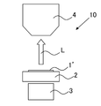
- FIG. 4 shows an example of an embodiment of a detection device used in the biological substance detection method.
- 5(a) to 5(c) show how biological substances are detected.
- the detection device 10 includes a detection chip 2 in which a well array 1' having a plurality of wells 1 is arranged, a detection section 4, and a magnetic field application section 3.
- the detection chip 2 is not particularly limited, and is configured in the same manner as a known detection chip used for observing biological substances.
- the magnetic field application unit 3 is not particularly limited, and is composed of a permanent magnet, an electromagnet, or the like.
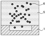
- the sample liquid 5 prepared to have a concentration of the magnetic particles 6 of at least 5 ⁇ 10 7 particles/mL is stirred, for example, after the magnetic particles 6 capture the biological substance to form the capturing body.
- the sample liquid 5 is sent onto the well array 1' (see FIG. 5(a)). It should be noted that the number of magnetic particles 6 illustrated is simplified in order to avoid complication of the drawing.
- the magnetic particles 6 are attracted into the well 1 by the magnetic field applied from the magnetic field applying unit 3, and the plurality of magnetic particles 6 containing the trapping body are accommodated in the well 1 (FIG. 5 ( b) see). At this time, the surplus sample liquid 5 is sent out of the well array 1'.
- the plastic particles, the metal particles, or the ceramic particles are used instead of the magnetic particles 6, the plastic particles are settled in the well 1 by their own weight.
- the coloring agent is added to the well 1, and the well 1 is covered with a transparent glass plate 7 so that the magnetic particles 6 and the coloring agent do not escape from the well 1 (see FIG. 5(c)).
- a structure in which a hydrophobic solvent is dripped onto the upper portion of the well 1 to block the upper portion of the well 1 and a transparent glass plate 7 is placed thereon can also be used.
- the coloring agent may be added to the test liquid 5 in advance just before the test liquid 5 is sent onto the well array 1'. As the reaction between the biological substance captured by the capturing body and the coloring agent progresses, color development occurs due to this reaction. This color development is detected by the detector 4 as the color development L of the well 1 (see FIG. 4). In the case where the coloring agent causes fluorescence in the well 1, after the reaction, excitation light is irradiated from an arbitrary light source to generate fluorescence. to detect.
- the biological substance detection method described above all the particles are accommodated in the well to maintain the detection sensitivity, and the biological substance is detected using the test solution prepared to have a high concentration of the particles. It is possible to detect the biological substance at high speed by shortening the reaction time required for capturing the biological substance.
- the well array of the present invention is used in the method for detecting a biological substance of the present invention, and the number of accommodation in each well is at least the minimum average number of accommodation N min represented by the following formulas (1) and (2).
- a plurality of particles containing the trapping bodies can be accommodated. According to the well array, all the particles are accommodated in the wells to maintain detection sensitivity, and the test solution prepared to have a high concentration of the particles is used to capture the biological substance. The required reaction time can be shortened and the biological substance can be detected at high speed.
- C represents the concentration of the particles in the test liquid, which is 5 ⁇ 10 7 particles/mL at the lowest.
- VL indicates the amount of the test solution, which is at least 5 ⁇ L.
- P total indicates the number of pixels of the imaging device, which is at least 300,000 pixels.
- P image indicates the number of pixels in a pixel group used for imaging one well in the imaging device, and is at least 9 pixels (3 ⁇ 3 pixels).
- the well array can be configured by applying the items described in the description of the biological substance detection method, and redundant description will be omitted.
- the detection device of the present invention comprises the detection chip on which the well array of the present invention is arranged, and the detection section including the imaging device having at least 300,000 pixels. According to the detection device, all the particles are accommodated in the well to maintain the detection sensitivity, and the test liquid prepared to have a high concentration of the particles is used to capture the biological substance. The required reaction time can be shortened and the biological substance can be detected at high speed.
- the detection device can be configured by applying the items described in the description of the biological material detection method, and redundant description will be omitted.
- the following detection test was performed using the influenza virus (biological material) as the detection target.
- the well array had a square opening shape of 10 ⁇ m on each side and a volume of 500 fL with a depth D of 5 ⁇ m. The one formed above was used.
- This well array was produced by a known shape processing method based on photolithography and dry etching.
- the particles for capturing the influenza virus magnetic particles having a diameter of 1 ⁇ m and having an anti-hemagglutinin antibody immobilized thereon were used.
- a reagent for detecting the influenza virus (4-methylumbelliferyl)- ⁇ -DN-acetylneuraminic acid (MUNANA, manufactured by Toronto Research Chemicals, Inc.), which is a reagent that generates a fluorescent substance by an enzymatic reaction.
- CMOS camera 2,048 ⁇ 2,048 pixels (4,194,304 pixels, P total ) (manufactured by Hamamatsu Photonics, ORCA-Flash 4.0 V3) was used.
- the magnetic particles were drawn into the well array using a magnet, the well array was sealed with fluorine oil, covered with a cover glass, and observed with a fluorescence microscope (Olympus, BXFM). Observation was performed under the condition of using an objective lens with a magnification of 4 times under the condition that each of the wells was observed with 64 pixels (8 ⁇ 8 pixels, P image ) of the CMOS camera.
- the enzymatic reaction between the influenza virus drawn into the wells and the MUNANA produces a fluorescent substance, 4-methylumbelliferone.
- the wells containing the influenza virus were detected as luminescent wells because an increase in luminescence due to the enzyme reaction was observed.
- the number of luminescent wells for 20 minutes of enzyme reaction time was counted, normalized by the number of wells used for observation, and the obtained value was used as a measured value corresponding to the concentration of the influenza virus.
- the results of this test are shown in FIG.
- the measured value of the number of luminescent wells correlates with the concentration of the influenza virus, and it is confirmed that it tends to increase as the concentration of the influenza virus increases.
- the presence and concentration of the influenza virus can be detected from the number of luminescent wells.
- the detection limit determined by ⁇ + 3.3 ⁇ is , 1 ⁇ 10 2 copies/mL.
- the capture time by the magnetic particles was 10 minutes, and the measurement time including the enzyme reaction time (20 minutes) was approximately 30 minutes.
- the lower limit of detection is an extremely small value, and the measurement time is extremely short, which is superior to the PCR method currently widely used as a highly sensitive virus detection method.
- the value of N min determined by the above formula (1) is about 95, and the average number of the magnetic particles contained in the well is about 260, defined by the above formula (2). satisfies the condition of N min . That is, the present invention realizes high-speed and highly sensitive biosubstance detection.
Landscapes
- Health & Medical Sciences (AREA)
- Life Sciences & Earth Sciences (AREA)
- Immunology (AREA)
- Chemical & Material Sciences (AREA)
- Engineering & Computer Science (AREA)
- Biomedical Technology (AREA)
- Physics & Mathematics (AREA)
- Hematology (AREA)
- Analytical Chemistry (AREA)
- General Health & Medical Sciences (AREA)
- Molecular Biology (AREA)
- Urology & Nephrology (AREA)
- Pathology (AREA)
- General Physics & Mathematics (AREA)
- Biochemistry (AREA)
- Medicinal Chemistry (AREA)
- Food Science & Technology (AREA)
- Biotechnology (AREA)
- Microbiology (AREA)
- Cell Biology (AREA)
- Virology (AREA)
- Chemical Kinetics & Catalysis (AREA)
- Clinical Laboratory Science (AREA)
- Tropical Medicine & Parasitology (AREA)
- Biophysics (AREA)
- Plasma & Fusion (AREA)
- Nuclear Medicine, Radiotherapy & Molecular Imaging (AREA)
- Dispersion Chemistry (AREA)
- Measuring Or Testing Involving Enzymes Or Micro-Organisms (AREA)
- Apparatus Associated With Microorganisms And Enzymes (AREA)
Priority Applications (3)
| Application Number | Priority Date | Filing Date | Title |
|---|---|---|---|
| US18/552,371 US20240302371A1 (en) | 2021-03-26 | 2022-03-04 | Biological substance detection method using well array and particles, well array, and detection device |
| JP2023508906A JPWO2022202218A1 (pt) | 2021-03-26 | 2022-03-04 | |
| EP22775014.8A EP4296653A1 (en) | 2021-03-26 | 2022-03-04 | Biological substance detection method using well array and particles, well array, and detection device |
Applications Claiming Priority (2)
| Application Number | Priority Date | Filing Date | Title |
|---|---|---|---|
| JP2021053011 | 2021-03-26 | ||
| JP2021-053011 | 2021-03-26 |
Publications (1)
| Publication Number | Publication Date |
|---|---|
| WO2022202218A1 true WO2022202218A1 (ja) | 2022-09-29 |
Family
ID=83396958
Family Applications (1)
| Application Number | Title | Priority Date | Filing Date |
|---|---|---|---|
| PCT/JP2022/009369 WO2022202218A1 (ja) | 2021-03-26 | 2022-03-04 | ウエルアレイと粒子とを用いた生体物質検出方法、ウエルアレイ及び検出装置 |
Country Status (4)
| Country | Link |
|---|---|
| US (1) | US20240302371A1 (pt) |
| EP (1) | EP4296653A1 (pt) |
| JP (1) | JPWO2022202218A1 (pt) |
| WO (1) | WO2022202218A1 (pt) |
Citations (8)
| Publication number | Priority date | Publication date | Assignee | Title |
|---|---|---|---|---|
| JP3886161B2 (ja) | 1997-03-14 | 2007-02-28 | トラスティーズ・オブ・タフツ・カレッジ | コード化微小球による光ファイバーセンサー |
| JP2010112777A (ja) | 2008-11-05 | 2010-05-20 | Saitama Univ | ウィルス、微生物類の検出方法 |
| WO2012121310A1 (ja) | 2011-03-08 | 2012-09-13 | 独立行政法人科学技術振興機構 | ビーズ封入方法、ターゲット分子を検出する方法、アレイ、キット及びターゲット分子検出装置 |
| JP5363663B2 (ja) | 2010-03-01 | 2013-12-11 | クワンテリクス コーポレーション | 分子または粒子を検出するアッセイにおけるダイナミックレンジを拡張するための方法またはシステム |
| JP5551798B2 (ja) | 2010-03-01 | 2014-07-16 | クワンテリクス コーポレーション | ビーズまたは他の捕捉物を用いた分子または粒子の超高感度検出 |
| WO2016006208A1 (ja) | 2014-07-08 | 2016-01-14 | 国立研究開発法人科学技術振興機構 | 物質封入方法及びターゲット分子を検出する方法 |
| JP2018091737A (ja) | 2016-12-05 | 2018-06-14 | 国立大学法人 東京大学 | 蛍光観察装置 |
| WO2018181488A1 (ja) * | 2017-03-29 | 2018-10-04 | 国立研究開発法人科学技術振興機構 | 微小物質検出方法及び微小物質検出用デバイス |
-
2022
- 2022-03-04 EP EP22775014.8A patent/EP4296653A1/en active Pending
- 2022-03-04 US US18/552,371 patent/US20240302371A1/en active Pending
- 2022-03-04 WO PCT/JP2022/009369 patent/WO2022202218A1/ja active Application Filing
- 2022-03-04 JP JP2023508906A patent/JPWO2022202218A1/ja active Pending
Patent Citations (8)
| Publication number | Priority date | Publication date | Assignee | Title |
|---|---|---|---|---|
| JP3886161B2 (ja) | 1997-03-14 | 2007-02-28 | トラスティーズ・オブ・タフツ・カレッジ | コード化微小球による光ファイバーセンサー |
| JP2010112777A (ja) | 2008-11-05 | 2010-05-20 | Saitama Univ | ウィルス、微生物類の検出方法 |
| JP5363663B2 (ja) | 2010-03-01 | 2013-12-11 | クワンテリクス コーポレーション | 分子または粒子を検出するアッセイにおけるダイナミックレンジを拡張するための方法またはシステム |
| JP5551798B2 (ja) | 2010-03-01 | 2014-07-16 | クワンテリクス コーポレーション | ビーズまたは他の捕捉物を用いた分子または粒子の超高感度検出 |
| WO2012121310A1 (ja) | 2011-03-08 | 2012-09-13 | 独立行政法人科学技術振興機構 | ビーズ封入方法、ターゲット分子を検出する方法、アレイ、キット及びターゲット分子検出装置 |
| WO2016006208A1 (ja) | 2014-07-08 | 2016-01-14 | 国立研究開発法人科学技術振興機構 | 物質封入方法及びターゲット分子を検出する方法 |
| JP2018091737A (ja) | 2016-12-05 | 2018-06-14 | 国立大学法人 東京大学 | 蛍光観察装置 |
| WO2018181488A1 (ja) * | 2017-03-29 | 2018-10-04 | 国立研究開発法人科学技術振興機構 | 微小物質検出方法及び微小物質検出用デバイス |
Non-Patent Citations (8)
| Title |
|---|
| DAVID M RISSIN ET AL., ANALYTICAL CHEMISTRY, vol. 83, 2011, pages 2279 |
| DAVID M RISSIN ET AL., NATURE BIOTECHNOLOGY, vol. 28, no. 6, 2010, pages 595 |
| ELENA PEREZ-RUIZ ET AL., ANALYTICA CHIMICA ACTA, vol. 1015, 2018, pages 74 |
| KAZUHITO V. TABATA, YOSHIHIRO MINAGAWA, YUKO KAWAGUCHI, MANA ONO, YOSHIKI MORIIZUMI, SEIYA YAMAYOSHI, YOICHIRO FUJIOKA, YUSUKE OHB: "Antibody-free digital influenza virus counting based on neuraminidase activity", SCIENTIFIC REPORTS, vol. 9, no. 1, 1 December 2019 (2019-12-01), XP055676628, DOI: 10.1038/s41598-018-37994-6 * |
| LEIRS KAREN, TEWARI KUMAR PHALGUNI, DECROP DEBORAH, PÉREZ-RUIZ ELENA, LEBLEBICI PELIN, VAN KELST BRAM, COMPERNOLLE GRIET, MEEUWS H: "Bioassay Development for Ultrasensitive Detection of Influenza A Nucleoprotein Using Digital ELISA", ANALYTICAL CHEMISTRY, AMERICAN CHEMICAL SOCIETY, US, vol. 88, no. 17, 6 September 2016 (2016-09-06), US , pages 8450 - 8458, XP055969682, ISSN: 0003-2700, DOI: 10.1021/acs.analchem.6b00502 * |
| MINAGAWA YOSHIHIRO, UENO HIROSHI, TABATA KAZUHITO V., NOJI HIROYUKI: "Mobile imaging platform for digital influenza virus counting", LAB ON A CHIP, ROYAL SOCIETY OF CHEMISTRY, UK, vol. 19, no. 16, 6 August 2019 (2019-08-06), UK , pages 2678 - 2687, XP055969681, ISSN: 1473-0197, DOI: 10.1039/C9LC00370C * |
| SOO HYEON KIM ET AL., LAB ON A CHIP, vol. 12, 2012, pages 4986 |
| STEPHANIE M. SCHUBERT ET AL., ANALYTICAL CHEMISTRY, vol. 88, 2016, pages 8450 |
Also Published As
| Publication number | Publication date |
|---|---|
| US20240302371A1 (en) | 2024-09-12 |
| EP4296653A1 (en) | 2023-12-27 |
| JPWO2022202218A1 (pt) | 2022-09-29 |
Similar Documents
| Publication | Publication Date | Title |
|---|---|---|
| US20230071162A1 (en) | Methods and apparatus for magnetic multi-bead assays | |
| EP3017286B1 (en) | A method, kit and system for imaging a blood sample | |
| TWI639703B (zh) | 樣本使用最大化之系統及方法 | |
| AU2008207835B2 (en) | System and probe composition for cell counting and analysis | |
| Teste et al. | Microchip integrating magnetic nanoparticles for allergy diagnosis | |
| US20220011315A1 (en) | Non-enzymatic glow assays | |
| JP2008514955A (ja) | サンプル分析システムおよび方法 | |
| EP2960651B1 (en) | Bioanalysis device and biomolecule analyser | |
| US11112347B2 (en) | Classifying microbeads in near-field imaging | |
| WO2020235607A1 (ja) | 標的分子の検出方法 | |
| US11609233B2 (en) | Indicator-based analysis of a sample | |
| Guo et al. | Multiplexed Luminescence Oxygen Channeling Immunoassay Based on Dual‐Functional Barcodes with a Host–Guest Structure: A Facile and Robust Suspension Array Platform | |
| ES2266297T3 (es) | Procedimiento y equipo de analisis para la deteccion de analitos en una muestra. | |
| US10429387B2 (en) | Simple and affordable method for immuophenotyping using a microfluidic chip sample preparation with image cytometry | |
| WO2022202218A1 (ja) | ウエルアレイと粒子とを用いた生体物質検出方法、ウエルアレイ及び検出装置 | |
| US20240168023A1 (en) | Virus detection method using well array, well array, and detection device | |
| US20230221319A1 (en) | A Method, A System, An Article, A Kit And Use Thereof For Biomolecule, Bioorganelle, Bioparticle, Cell And Microorganism Detection | |
| WO2019131592A1 (ja) | 標的分子の検出における偽陰性判定の発生を抑制する方法および検出デバイス | |
| CN1598579A (zh) | 以磁性微球介导的微流体分析系统及其检测方法 | |
| KR102543112B1 (ko) | 유체 시료 내에 극미량으로 존재하는 분석 대상 물질의 입자를 검출하기 위한 방법 | |
| US20210322988A1 (en) | Microfluidic droplet-based assay process and apparatus | |
| Rodriguez | The development of microbead-based immunoassays: An application of the “electronic taste chip” |
Legal Events
| Date | Code | Title | Description |
|---|---|---|---|
| 121 | Ep: the epo has been informed by wipo that ep was designated in this application |
Ref document number: 22775014 Country of ref document: EP Kind code of ref document: A1 |
|
| ENP | Entry into the national phase |
Ref document number: 2023508906 Country of ref document: JP Kind code of ref document: A |
|
| WWE | Wipo information: entry into national phase |
Ref document number: 2022775014 Country of ref document: EP |
|
| ENP | Entry into the national phase |
Ref document number: 2022775014 Country of ref document: EP Effective date: 20230920 |
|
| NENP | Non-entry into the national phase |
Ref country code: DE |