WO2022202159A1 - タイヤ消耗度管理装置 - Google Patents
タイヤ消耗度管理装置 Download PDFInfo
- Publication number
- WO2022202159A1 WO2022202159A1 PCT/JP2022/008798 JP2022008798W WO2022202159A1 WO 2022202159 A1 WO2022202159 A1 WO 2022202159A1 JP 2022008798 W JP2022008798 W JP 2022008798W WO 2022202159 A1 WO2022202159 A1 WO 2022202159A1
- Authority
- WO
- WIPO (PCT)
- Prior art keywords
- vehicle
- coefficient
- friction coefficient
- tire wear
- friction
- Prior art date
- Legal status (The legal status is an assumption and is not a legal conclusion. Google has not performed a legal analysis and makes no representation as to the accuracy of the status listed.)
- Ceased
Links
Images






Classifications
-
- B—PERFORMING OPERATIONS; TRANSPORTING
- B60—VEHICLES IN GENERAL
- B60C—VEHICLE TYRES; TYRE INFLATION; TYRE CHANGING; CONNECTING VALVES TO INFLATABLE ELASTIC BODIES IN GENERAL; DEVICES OR ARRANGEMENTS RELATED TO TYRES
- B60C19/00—Tyre parts or constructions not otherwise provided for
-
- G—PHYSICS
- G01—MEASURING; TESTING
- G01M—TESTING STATIC OR DYNAMIC BALANCE OF MACHINES OR STRUCTURES; TESTING OF STRUCTURES OR APPARATUS, NOT OTHERWISE PROVIDED FOR
- G01M17/00—Testing of vehicles
- G01M17/007—Wheeled or endless-tracked vehicles
- G01M17/02—Tyres
-
- G—PHYSICS
- G01—MEASURING; TESTING
- G01N—INVESTIGATING OR ANALYSING MATERIALS BY DETERMINING THEIR CHEMICAL OR PHYSICAL PROPERTIES
- G01N3/00—Investigating strength properties of solid materials by application of mechanical stress
- G01N3/56—Investigating resistance to wear or abrasion
Definitions
- the present invention relates to a tire wear management device.
- This application claims priority based on Japanese Patent Application No. 2021-048548 filed on March 23, 2021, the contents of which are incorporated herein.
- An object of the present invention is to provide a tire wear degree management device capable of accurately deriving the wear degree of a tire.
- a tire wear management device includes: an acquisition unit that acquires distance information indicating a traveled distance of a vehicle and situation information indicating a situation during travel of the vehicle; a calculation unit that calculates the degree of wear of the tires of the vehicle based on the distance information and the situation information that have been received.
- a second aspect is the tire wear degree management device according to the first aspect, wherein the coefficient relation information prepared for each of a plurality of situations according to the load on the tire is referred to and acquired by the acquisition unit. further comprising a determining unit configured to determine a friction coefficient according to a running condition of the vehicle indicated by the condition information, wherein the calculating unit includes the friction coefficient determined by the determining unit and the coefficient of friction acquired by the acquiring unit; A degree of tire wear of the vehicle may be calculated based on the distance information.
- a third aspect is the tire wear degree management device according to the second aspect, wherein the acquisition unit acquires information indicating a date on which the vehicle traveled, and the determination unit is prepared for each season.
- a seasonal friction coefficient corresponding to the season on which the vehicle traveled may be selected from among the plurality of seasonal friction coefficients, and the friction coefficient may be determined based on the selected seasonal friction coefficient.
- a fourth aspect is the tire wear degree management device according to the second or third aspect, wherein the acquisition unit acquires information indicating the date and time when the vehicle traveled, and the determination unit acquires selects from among a plurality of temperature friction coefficients that increase as the temperature of the vehicle increases and decreases as the temperature during travel decreases, according to the temperature at the time the vehicle travels, and selects the temperature
- the coefficient of friction may be determined based on the coefficient of friction.
- a fifth aspect is the tire wear management device according to any one aspect of (2) to (4) above, wherein the acquisition unit acquires information indicating the date and time when the vehicle traveled, The determination unit selects a first weighting coefficient that increases as the humidity during travel is lower and decreases as the humidity during travel is higher, according to the humidity at the date and time when the vehicle travels. A factor may be selected and the coefficient of friction determined based on the selected first weighting factor.
- a sixth aspect is the tire wear management device according to any one of the second to fifth aspects, wherein the acquiring unit acquires information about a vehicle speed during running of the vehicle, and determines The second weighting factor corresponding to the degree of sudden acceleration occurring in the vehicle is selected from a plurality of second weighting factors that increase as the amount of sudden acceleration during travel increases and decrease as the amount of sudden acceleration during travel decreases.
- a weighting factor may be selected and the coefficient of friction may be determined based on the selected second weighting factor.
- a seventh aspect is the tire wear management device according to any one of the second to sixth aspects, wherein the acquiring unit acquires information about braking during running of the vehicle, and determines The third weighting factor corresponding to the degree of sudden braking that occurs in the vehicle is selected from a plurality of third weighting factors that increase as the amount of sudden braking during travel increases and decrease as the amount of sudden braking during travel decreases. A weighting factor may be selected and the friction factor may be determined based on the selected third weighting factor.
- a ninth aspect is the tire wear management device according to any one of the second to eighth aspects, wherein the acquiring unit acquires information indicating the date and time and position of the vehicle traveled, The determination unit selects a weather friction coefficient according to the date and time the vehicle travels from among a plurality of weather friction coefficients prepared for each weather, and selects the weather friction coefficient based on the selected weather friction coefficient. may be determined.
- a tenth aspect is the tire wear management device according to any one of the second to ninth aspects, wherein the acquisition unit acquires information about a vehicle speed at which the vehicle travels, and the determination unit is a fifth weight corresponding to the vehicle speed when the vehicle is running, from among a plurality of fifth weighting factors that increase as the vehicle speed increases and decrease as the vehicle speed decreases.
- a coefficient may be selected and the coefficient of friction determined based on the selected fifth weighting factor.
- An eleventh aspect is the tire wear degree management device according to any one of the first to tenth aspects, further comprising a notification unit for notifying a user of the wear degree calculated by the calculation unit. good too.
- the first aspect it is possible to accurately derive the degree of wear of the tire according to the conditions during running of the vehicle.
- the second aspect it is possible to easily and accurately calculate the degree of wear of the tire by using the friction coefficient prepared according to the running conditions.
- the third aspect it is possible to accurately derive the degree of tire wear, taking into account that the road temperature changes according to the season and the load on the tires varies.
- the fourth aspect it is possible to accurately derive the degree of tire wear, taking into consideration that the load on the tires varies depending on the air temperature during travel.
- the degree of tire wear is possible to derive the degree of tire wear with high accuracy, taking into consideration that the load on the tire varies depending on the humidity during running.
- the sixth aspect it is possible to derive the degree of tire wear with high accuracy, taking into consideration that the load on the tire varies depending on the degree of rapid acceleration.
- the seventh aspect it is possible to accurately derive the degree of wear of the tire, considering that the load on the tire varies depending on the degree of sudden braking.
- the eighth aspect it is possible to derive the degree of tire wear with high accuracy, taking into account that the load on the tires varies depending on the air temperature during running.
- the ninth aspect it is possible to accurately derive the degree of tire wear, taking into consideration that the load on the tires varies depending on the weather during driving.
- the tenth aspect it is possible to derive the degree of tire wear with high accuracy, taking into consideration that the load on the tire varies depending on the speed during running.
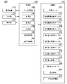
- FIG. 1 is a functional block diagram of a motorcycle;
- FIG. It is a functional block diagram of a tire wear degree management server.
- It is a figure which shows an example of the content of vehicle data.
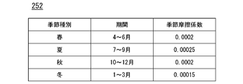
- It is a figure which shows an example of the content of a seasonal friction coefficient table.
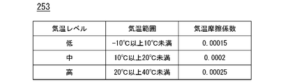
- FIG. 5 is a diagram showing an example of contents of a temperature friction coefficient table;
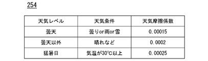
- It is a figure which shows an example of the content of a weather friction coefficient table.
- FIG. 10 is a diagram showing an example of the contents of a first weighting factor table;
- FIG. 10 is a diagram showing an example of the contents of a second weighting factor table;
- FIG. 2 is a functional block diagram of the motorcycle 100. As shown in FIG. Although the motorcycle 100 will be described, the motorcycles 100A, 100B, .
- the motorcycle 100 includes, for example, a communication device 111, a GNSS receiver 112, an ignition switch 113, an accelerator grip 114, a brake lever 115, a vehicle speed measurement unit 116, an engine 117, a braking device 118, a travel distance It includes a measurement unit 119 , a display device 120 , a control unit 130 and a storage unit 140 .
- the communication device 111 includes, for example, a communication interface such as NIC.
- the communication device 111 communicates with the tire wear degree management server 200 and the like via a communication network such as the Internet under the control of the control unit 130 .
- the GNSS receiver 112 receives signals from GNSS (Global Navigation Satellite System) satellites.
- the ignition switch 113 is the main power switch of the motorcycle 100 .
- Accelerator grip 114 is equipped with a sensor that detects the amount of operation or the presence or absence of an operation, and receives an acceleration instruction.
- the brake lever 115 is equipped with a sensor that detects the amount of operation or the presence or absence of operation, and receives braking instructions such as deceleration and stopping.
- Vehicle speed measurement unit 116 detects the running speed of motorcycle 100 .
- the vehicle speed measurement unit 116 includes a wheel speed sensor attached to a wheel of the motorcycle 100 and a speed calculator. It is derived and output to control unit 130 .
- the engine 117 outputs running driving force (torque) for the motorcycle 100 to run to the driving wheels.
- Engine 117 includes, for example, an internal combustion engine, an electric motor, and a transmission.
- the brake device 118 includes, for example, a brake caliper, a cylinder that transmits hydraulic pressure to the brake caliper, and an electric motor that generates hydraulic pressure in the cylinder.
- Travel distance measurement unit 119 measures the travel distance of motorcycle 100 .
- the travel distance measurement unit 119 includes a wheel rotation sensor attached to a wheel of the motorcycle 100 and a distance calculator, and derives the travel distance of the motorcycle 100 based on the wheel rotation speed detected by the wheel rotation sensor. , to the control unit 130 .
- the display device 120 includes, for example, an LCD (Liquid Crystal Display) or an organic EL (Electroluminescence) display. The display device 120 is installed at a position where the driver can easily see it while driving.
- the control unit 130 is, for example, an ECU (Electronic Control Unit).
- the control unit 130 is described as one block for the sake of simplification of explanation, but it is not limited to this and may be divided into a plurality of units.
- the control unit 130 includes, for example, a position specifying unit 131, a travel date and time recording unit 132, a vehicle speed recording unit 133, an engine control unit 134, a brake control unit 135, a travel distance recording unit 136, and a vehicle data generation unit. 137 , a transmission control unit 138 , and a display control unit 139 .
- Some or all of these functional units are implemented by a processor such as a CPU (Central Processing Unit) executing a program (software) stored in its own storage unit.
- a processor such as a CPU (Central Processing Unit) executing a program (software) stored in its own storage unit.
- some or all of the functions of these components include hardware (circuitry) such as LSI (Large Scale Integration), ASIC (Application Specific Integrated Circuit), and FPGA (Field-Programmable Gate Array).
- the program may be stored in advance in a storage device such as a HDD (Hard Disk Drive) or flash memory, or may be stored in a removable storage medium such as a DVD or CD-ROM. It may be installed by being worn.
- a storage device such as a HDD (Hard Disk Drive) or flash memory
- a removable storage medium such as a DVD or CD-ROM. It may be installed by being worn.
- the position specifying unit 131 specifies the position of the motorcycle 100 based on the signal received by the GNSS receiver 112 .
- the position of the motorcycle 100 is indicated by latitude and longitude.
- the position specifying unit 131 generates data (hereinafter referred to as position data) in which the information indicating the specified position of the motorcycle 100 is associated with the information indicating the date and time of measurement (the date and time when the position was specified). do.
- the position data includes, for example, at least one of the position and date and time when the ignition switch 113 is turned on, and the position and date and time when the ignition switch 113 is turned off.
- the travel date and time recording unit 132 generates information indicating the date and time when the motorcycle 100 traveled (hereinafter referred to as travel date and time data) and stores it as part of the log information 141 in the storage unit 140 .
- the date and time includes year, month, day and time.
- the travel date and time data includes, for example, the date and time when the ignition switch 113 was turned on and the date and time when the ignition switch 113 was turned off.
- the vehicle speed status recording unit 133 generates information about the traveling speed of the motorcycle 100 and stores it as part of the log information 141 in the storage unit 140 .
- the information about the running speed includes, for example, vehicle speed point data, sudden acceleration data, and sudden deceleration data.
- the vehicle speed point data is, for example, data in which the vehicle speed measured periodically (for example, every few minutes) by the vehicle speed measurement unit 116 is associated with the date and time when the vehicle speed was measured.
- the vehicle data generation unit 137 may generate information on braking during travel (hereinafter referred to as braking data) and include it in the vehicle data (one of the situation information).
- the braking data is information relating to sudden braking during traveling of the motorcycle 100, and the sudden braking means sudden braking.
- the braking data includes, for example, braking point data, braking frequency data, and braking frequency data.
- the brake point data is data indicating all dates and times when the brake lever 115 is operated.
- the number-of-brakes data is data indicating the number of brake instructions (braking instructions) received via the brake lever 115 within a predetermined time (for example, several minutes).
- the brake frequency data is data indicating the frequency (high, low, etc.) of brake instructions received via the brake lever 115 within a predetermined time (for example, several minutes).
- FIG. 3 is a functional block diagram of the tire wear management server 200.
- the tire wear management server 200 includes, for example, a communication device 210, an input unit 220, a display unit 230, a processing unit 240, and a storage unit 250.
- the communication device 210 includes, for example, a communication interface such as NIC.
- the communication device 210 communicates with the motorcycle 100, the user terminal device 300, and the weather information server 400 via a communication network such as the Internet under the control of the processing unit 240.
- FIG. 1 A communication network such as the Internet under the control of the processing unit 240.
- the input unit 220 includes, for example, some or all of various keys, buttons, dial switches, a mouse, and the like.
- the display unit 230 is, for example, an LCD or an organic EL display device.
- the storage unit 250 is realized by RAM, ROM, HDD, or the like, for example. In addition to storing programs executed by the processor, the storage unit 250 stores vehicle data 251, a seasonal friction coefficient table 252, a temperature friction coefficient table 253, a weather friction coefficient table 254, a first weighting coefficient table 255, and a second weighting coefficient table 256. , a third weighting factor table 257, a fourth weighting factor table 258, a fifth weighting factor table 259, consumption degree log data 260, setting information 261, weather history information 262, and the like. Details of each information will be described later.
- the determining unit 242 refers to the coefficient relation information prepared for each of a plurality of situations according to the load on the tire, and determines the friction coefficient according to the traveling situation of the motorcycle 100 indicated by the situation information.
- the coefficient-related information includes, for example, a seasonal friction coefficient table 252, a temperature friction coefficient table 253, a weather friction coefficient table 254, a first weight coefficient table 255, a second weight coefficient table 256, a third weight coefficient table 257, and a fourth weight.
- a coefficient table 258, a fifth weighting coefficient table 259, and the like are included. The details of the method of determining the coefficient of friction will be described later.
- the determination unit 242 may use a function formula prepared in advance to determine the friction coefficient according to the running conditions of the motorcycle 100 indicated by the condition information.
- the calculation unit 243 uses the following calculation model to calculate the wear level (hereinafter referred to as the first wear level) from when the ignition switch 113 of the motorcycle 100 is turned on to when it is turned off.
- the first degree of wear is indicated by, for example, the amount of tire wear (amount of wear).
- the calculation unit 243 stores, as part of the wear level log data 260, information in which information indicating the date and time of travel and the vehicle ID are associated with the calculated first wear level. An example of deriving the amount of wear as the degree of wear will be described below. Note that the degree of wear is not limited to the amount of wear, and may be indicated by degrees indicating the degree of wear.
- the calculation unit 243 calculates a comprehensive wear level (hereinafter referred to as a second wear level) up to the present time for each of the motorcycles 100, 100A, 100B, and so on.
- the second wear level is the sum of the first wear levels of the same vehicle ID among the first wear levels stored in the wear level log data 260 .
- the calculation unit 243 stores, as part of the consumption degree log data 260, information in which information indicating the calculated date and time and the vehicle ID are associated with the calculated second consumption degree.
- the determining unit 242 selects a seasonal friction coefficient corresponding to the season on which the motorcycle 100 travels from among a plurality of seasonal friction coefficients prepared for each season, and based on the selected seasonal friction coefficient, Determine the friction coefficient to be substituted into the wear amount calculation model.
- FIG. 5 is a diagram showing an example of the contents of the seasonal friction coefficient table 252.
- the seasonal friction coefficient table 252 is, for example, information that associates a season type with a period and a seasonal friction coefficient. Season types include spring, summer, autumn, and winter.
- the period is information indicating the period corresponding to each season.
- the seasonal friction coefficient is set so that it is high in summer, which is the season when the average temperature is high, and is low in winter, which is the season when the average temperature is low.
- the determination unit 242 selects a temperature friction coefficient according to the temperature at the time when the motorcycle 100 traveled from among a plurality of temperature friction coefficients prepared for each temperature, and based on the selected temperature friction coefficient, A friction coefficient to be substituted into the wear amount calculation model may be determined.
- FIG. 6 is a diagram showing an example of the contents of the temperature friction coefficient table 253.
- the temperature friction coefficient table 253 is, for example, information in which temperature levels are associated with temperature ranges and temperature friction coefficients. Temperature levels include, for example, low, medium, and high.
- the temperature range is information indicating the temperature range corresponding to each temperature level. The temperature friction coefficient is set so that it increases as the air temperature during running increases, and decreases as the air temperature during running decreases.
- the weather history information 262 is, for example, information obtained from the weather information server 400 via the network NW.
- the weather history information 262 includes information indicating past temperature, humidity, weather, etc. for each date and time and area.
- FIG. 7 is a diagram showing an example of the contents of the weather friction coefficient table 254.
- the weather friction coefficient table 254 is, for example, information in which a weather level is associated with a weather condition and a weather friction coefficient.
- Weather levels include, for example, cloudy, non-cloudy, extremely hot days, and the like.
- Weather conditions are information indicating weather conditions corresponding to each weather level.
- the weather friction coefficient is set so that it increases as the amount of sunshine during travel increases, and decreases as the amount of sunshine during travel decreases.
- the determining unit 242 refers to the weather history information 262 to determine the date and time included in the travel date and time data and the latitude included in the position data. And get the weather at the time of driving according to the longitude. Then, the determining unit 242 refers to the weather friction coefficient table 254 and determines the acquired weather friction coefficient corresponding to the weather during travel as the “basic friction coefficient”. Note that if there is a range in the weather during driving, the determining unit 242 determines the weather with the greatest amount of sunshine as the weather during driving.
- the determining unit 242 may determine a value obtained by multiplying the determined "basic friction coefficient" by a weighting factor corresponding to the situation during running as the friction coefficient to be substituted into the wear amount calculation model. Note that even when a plurality of conditions among the first to fifth weighting factors described below are met, the determining unit 242 multiplies the basic friction factor by any one to calculate the friction factor. Alternatively, the basic coefficient of friction may be multiplied by all matching weighting coefficients to calculate the coefficient of friction. Further, it may be determined whether or not there is a weighting factor that matches the running condition of the weighting factors selected to be used.
- the determination unit 242 selects a plurality of first weighting coefficients that increase as the humidity during travel is lower and decrease as the humidity during travel is higher, and selects a weight coefficient corresponding to the humidity at the date and time when the motorcycle 100 travels. A first weighting factor is selected, and a value obtained by multiplying the selected first weighting factor by the basic friction factor is determined as the friction factor.
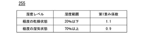
- FIG. 8 is a diagram showing an example of the contents of the first weighting factor table 255.
- the first weighting factor table 255 is, for example, information that associates a humidity level with a humidity range and a first weighting factor.
- Humidity levels include, for example, extreme dry conditions, extreme wet conditions, and the like.
- the humidity range is information indicating the humidity range corresponding to each humidity level.
- the first weighting factor is set to be greater than the reference value "1" in extremely dry conditions and less than the reference value "1" in extremely humid conditions.
- the determination unit 242 refers to the weather history information 262 and Get the humidity when driving based on latitude and longitude. Then, the determining unit 242 refers to the first weighting factor table 255 to determine whether the humidity during running matches the condition for multiplying the first weighting factor (whether it is included in the humidity range). If yes, then the base friction coefficient is multiplied by the first weighting factor to determine the friction coefficient.
- FIG. 9 is a diagram showing an example of the contents of the second weighting factor table 256.
- the second weighting factor table 256 is, for example, information that associates an acceleration level with a rapid acceleration condition and a second weighting factor.
- the acceleration level includes, for example, many sudden accelerations, few sudden accelerations, and the like.
- the rapid acceleration condition is information indicating a condition corresponding to each acceleration level, and is indicated, for example, by the number or frequency of occurrence of sudden acceleration.
- the second weighting factor is set to be larger than the reference value "1" when there are many sudden accelerations and to be smaller than the reference value "1" when there are few sudden accelerations.
- the determination unit 242 refers to the first weighting factor table 255 to determine the number and frequency of rapid acceleration during running. It is determined whether or not a rapid acceleration condition for multiplication by two weighting factors is met, and if so, the second weighting factor is multiplied by the basic friction coefficient to determine the friction coefficient.
- the determining unit 242 determines the degree of sudden braking that occurred in the motorcycle 100 from among a plurality of third weighting factors that increase as the amount of sudden braking during travel increases and decrease as the amount of sudden braking during travel decreases. is selected, and the friction coefficient is determined by multiplying the basic friction coefficient by the selected third weight coefficient.
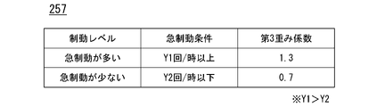
- FIG. 10 is a diagram showing an example of the contents of the third weighting factor table 257.
- the third weighting factor table 257 is, for example, information that associates a braking level with a sudden braking condition and a third weighting factor.
- the braking level includes, for example, frequent braking and less sudden braking.
- the sudden braking condition is information indicating conditions corresponding to each braking level, and is indicated by, for example, the number and frequency of occurrence of sudden braking and the number and frequency of occurrence of sudden deceleration.
- the third weighting factor is set to be larger than the reference value "1" when there is a lot of sudden braking and to be smaller than the reference value "1" when there is little sudden braking.
- the determining unit 242 refers to the third weighting factor table 257 to determine the number and frequency of sudden braking during running, or It is determined whether or not the number and frequency of decelerations meet the sudden braking condition multiplied by the third weighting factor.
- the determining unit 242 may set a plurality of threshold values that are larger than the reference value when the time zone of running is daytime and smaller than the reference value when the time zone of running is late at night or early in the morning.
- a fourth weighting factor corresponding to the date and time when the motorcycle 100 traveled is selected from among the four weighting factors, and a value obtained by multiplying the selected fourth weighting factor by the basic friction factor is determined as the friction factor.
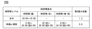
- FIG. 11 is a diagram showing an example of the contents of the fourth weighting factor table 258.
- the fourth weighting factor table 258 is, for example, information that associates a time slot level with a time slot condition and a fourth weighting factor.
- Time zone levels include, for example, daytime, early morning or late night.
- the time zone conditions are information indicating the time zone conditions corresponding to each time zone level for each season.
- the fourth weighting factor is set to be larger than the reference value "1" during the daytime in summer and to be smaller than the reference value "1" in the early morning and late night according to the season when the sunrise and sunset are different.
- the determination unit 242 selects the vehicle speed when the motorcycle 100 is running from among a plurality of fifth weighting factors that increase as the vehicle speed when running increases and decrease as the vehicle speed when running decreases. is selected, and the value obtained by multiplying the selected fifth weighting factor by the basic friction coefficient is determined as the friction coefficient.
- FIG. 12 is a diagram showing an example of the contents of the fifth weighting factor table 259.
- the fifth weighting factor table 259 is, for example, information that associates a vehicle speed level with a vehicle speed condition and a fifth weighting factor.
- Vehicle speed levels include, for example, low speed and high speed.
- the vehicle speed condition is a condition indicating the range of vehicle speeds corresponding to each vehicle speed level.
- the fifth weighting factor is set to be larger than the reference value "1" when the running speed is slow and smaller than the reference value "1" when the running speed is fast.
- the determining unit 242 refers to the fifth weighting factor table 259 and multiplies the fifth weighting factor by the running speed. It is determined whether or not the time zone condition is met, and if the condition is met, the basic friction coefficient is multiplied by the fifth weighting factor to determine the friction coefficient. Since there is a range of speeds during running, the determination unit 242 determines the activation period from when the ignition switch 113 of the motorcycle 100 is turned on to when it is turned off by a plurality of values according to the speed during running. The friction coefficient may be determined by dividing into sub-sections and multiplying the basic friction coefficient by a fifth weighting factor that matches each divided sub-section.
- the determination unit 242 determines the friction coefficient by multiplying the basic friction coefficient by the low-speed fifth weighting factor for the low-speed section, and multiplies the high-speed fifth weighting factor for the high-speed section.
- the friction coefficient is determined by multiplying the coefficient, and the basic friction coefficient that does not ride the fifth weighting coefficient is determined as the friction coefficient in the section where the vehicle travels at a speed that does not correspond to low speed or high speed, and these friction coefficients are added up. good.
- FIG. 13 is a flow chart showing the flow of processing by the tire wear management server 200. As shown in FIG. In this flowchart, processing for each motorcycle 100 will be described.
- the data management unit 241 determines whether vehicle data has been received from the motorcycle 100 (step S101). When vehicle data is received, the determining unit 242 determines whether or not the setting information 261 is set to determine the friction coefficient based on the seasonal friction coefficient (step S102). If it is set in the setting information 261 to determine the friction coefficient based on the seasonal friction coefficient, the determination unit 242 determines the seasonal friction coefficient selected based on the travel date as the “basic friction coefficient” (step S103).
- the determining unit 242 sets the setting information 261 to determine the friction coefficient based on the temperature friction coefficient. It is determined whether or not there is (step S104).
- the determining unit 242 determines the temperature friction coefficient selected based on the temperature during running as the “basic friction coefficient”. (Step S105).
- the determination unit 242 selects the weather friction coefficient selected based on the weather at the time of travel as " basic friction coefficient” (step S106).
- the determining unit 242 determines whether or not the conditions during running match the conditions of the weighting factors that are set to be adopted among the first to fifth weighting factors (step S107). If the condition of the weighting factor is met by the running condition, the determination unit 242 selects the weighting factor of the condition that matches the running condition, and multiplies the weighting factor by the "basic friction coefficient" to determine the friction coefficient (step S108).
- the determining unit 242 determines the basic friction coefficient determined in step S103, S105, or S106 or the basic friction coefficient multiplied by the weighting factor in step S108 as the friction coefficient to be substituted into the wear amount calculation model. (step S109).
- the calculator 243 calculates the degree of wear based on the determined friction coefficient and section travel distance data (step S110).
- the acquisition unit (data management unit 241) that acquires the distance information indicating the traveling distance of the motorcycle 100 and the situation information indicating the state of the vehicle during travel, and the data management unit 241 obtains a calculation unit 243 for calculating the degree of wear of the tire of the motorcycle 100 based on the distance information and the situation information thus obtained. Since the wear rate of the tire can be calculated, the wear rate of the tire can be derived with high accuracy.
- the tire wear degree management server 200 has a function of calculating the tire wear degree
- the motorcycle 100 or the user terminal device 300 may have a function of calculating tire wear.
- the illustrated description of the tire wear degree management server 200 may be replaced.
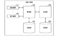
- FIG. 14 shows a configuration in which the motorcycle 100 has a function of calculating tire wear.
- the present invention is not limited to the above embodiments, and for example, the present system is not limited to being applied to motorcycles, and can be widely applied to straddle-type vehicles.
- the straddle-type vehicle includes all vehicles in which the driver straddles the vehicle body, not only motorcycles (including motorized bicycles and scooter-type vehicles), but also three-wheeled vehicles (one front wheel and two rear wheels). , including vehicles with two front wheels and one rear wheel) or vehicles with four wheels. Also included are vehicles whose prime mover includes an electric motor. Moreover, you may apply to the motor vehicle which has a compartment.
- the present invention may be applied to various devices that require communication. For example, it may be applied to devices such as storage boxes and bags having communication functions.
- the present system is not limited to straddle-type vehicles, and may be applied to vehicles with four or more wheels, such as sedans, that can accommodate multiple people.
- Tire wear management system 100 motorcycle (straddle-type vehicle) 111 communication device 112 GNSS receiver 113 ignition switch 114 accelerator grip 115 brake lever 116 vehicle speed measurement unit 117 engine 118 brake device 119 mileage measurement unit 120 display device 130 control unit 131 position specifying unit 132 traveling date and time recording unit 133 vehicle speed condition recording unit 134 engine control unit 135 brake control unit 136 mileage recording unit 137 vehicle data generation unit 138 transmission control unit 139 display control unit 140 storage unit 141 log information 142 vehicle data 200 tire wear management server 210 communication device 220 input unit 230 display unit 240 processing unit 241 data management unit 242 determination unit 243 calculation unit 244 notification unit 245 setting change unit 246 display control unit 250 storage unit 251 vehicle data 252 season friction coefficient table 253 temperature friction coefficient table 254 weather friction coefficient table 255 first weighting coefficient Table 256 Second weighting factor table 257 Third weighting factor table 258 Fourth weighting factor table 259 Fifth weighting factor table 260 Consumption log data 261 Setting information 262 Weather history information 300 User terminal device 400 Weather information server
Landscapes
- Physics & Mathematics (AREA)
- General Physics & Mathematics (AREA)
- Chemical & Material Sciences (AREA)
- Mechanical Engineering (AREA)
- Health & Medical Sciences (AREA)
- Life Sciences & Earth Sciences (AREA)
- Engineering & Computer Science (AREA)
- Analytical Chemistry (AREA)
- Biochemistry (AREA)
- General Health & Medical Sciences (AREA)
- Immunology (AREA)
- Pathology (AREA)
- Traffic Control Systems (AREA)
Abstract
Description
本願は、2021年3月23日に出願された日本国特許出願2021-048548号に基づき優先権を主張し、その内容をここに援用する。
図2は、自動二輪車100の機能ブロック図である。自動二輪車100について説明するが、自動二輪車100A,100B…も同じ構成であってよく、その詳細な説明は省略する。
これらの機能部のうち一部または全部は、例えば、CPU(Central Processing Unit)などのプロセッサが、自身の記憶部に記憶されたプログラム(ソフトウェア)を実行することで実現される。また、これらの構成要素の機能のうち一部または全部は、LSI(Large Scale Integration)やASIC(Application Specific Integrated Circuit)、FPGA(Field-Programmable Gate Array)等のハードウェア(回路部:circuitryを含む)によって実現されていてもよいし、ソフトウェアとハードウェアの協働によって実現されていてもよい。プログラムは、予めHDD(Hard Disk Drive)やフラッシュメモリなどの記憶装置に格納されていてもよいし、DVDやCD-ROMなどの着脱可能な記憶媒体に格納されており、記憶媒体がドライブ装置に装着されることでインストールされてもよい。
図3は、タイヤ消耗度管理サーバ200の機能ブロック図である。タイヤ消耗度管理サーバ200は、例えば、通信装置210と、入力部220と、表示部230と、処理部240と、記憶部250とを備える。
記憶部250は、例えば、RAM、ROM、HDDなどによって実現される。記憶部250は、プロセッサが実行するプログラムを格納する他、車両データ251、季節摩擦係数テーブル252、気温摩擦係数テーブル253、天気摩擦係数テーブル254、第1重み係数テーブル255、第2重み係数テーブル256、第3重み係数テーブル257、第4重み係数テーブル258、第5重み係数テーブル259、消耗度ログデータ260、設定情報261、天気履歴情報262等を格納する。各情報の詳細については後述する。
タイヤの摩耗量(mm)=走行距離(Km)×摩耗係数(mm/Km)
算出モデルにおける走行距離は、区間走行距離データに含まれる距離であって、起動期間(自動二輪車100のイグニッションスイッチ113がONされた時点からOFFされる時点までの期間)において走行した距離である。
例えば、決定部242は、季節ごとに用意された複数の季節摩擦係数の中から、自動二輪車100が走行した日付の季節に応じた季節摩擦係数を選択し、選択した季節摩擦係数に基づいて、摩耗量の算出モデルに代入する摩擦係数を決定する。
季節種別には、春、夏、秋、冬が含まれる。期間は、各季節に該当する期間を示す情報である。季節摩擦係数は、平均気温が高い季節である夏において高く、平均気温が低い季節である冬において低くなるように設定されている。
また、決定部242は、気温ごとに用意された複数の気温摩擦係数の中から、自動二輪車100が走行した日時の気温に応じた気温摩擦係数を選択し、選択した気温摩擦係数に基づいて、摩耗量の算出モデルに代入する摩擦係数を決定してもよい。
また、決定部242は、天気ごとに用意された複数の天気摩擦係数の中から、自動二輪車100が走行した日時および位置に応じた天気摩擦係数を選択し、選択した天気摩擦係数に基づいて、第1摩耗量の算出モデルの摩擦係数を決定してもよい。
例えば、決定部242は、走行時の湿度が低いほど大きくなり、且つ、走行時の湿度が高いほど小さくなる複数の第1重み係数の中から、自動二輪車100が走行した日時の湿度に応じた第1重み係数を選択し、選択した第1重み係数を基本摩擦係数に乗算した値を、摩擦係数を決定する。
例えば、決定部242は、走行時の急加速が多いほど大きくなり、且つ、走行時の急加速が少ないほど小さくなる複数の第2重み係数の中から、自動二輪車100において発生した急加速の程度に応じた第2重み係数を選択し、選択した第2重み係数を基本摩擦係数に乗算した値を、摩擦係数を決定する。
例えば、決定部242は、走行時の急制動が多いほど大きくなり、且つ、走行時の急制動が少ないほど小さくなる複数の第3重み係数の中から、自動二輪車100において発生した急制動の程度に応じた第3重み係数を選択し、選択した第3重み係数を基本摩擦係数に乗算した値を、摩擦係数を決定する。
例えば、決定部242は、走行時の時間帯が日中である場合に基準値よりも大きくなり、且つ、走行時の時間帯が深夜あるいは早朝である場合に基準値よりも小さくなる複数の第4重み係数の中から、自動二輪車100が走行した日時に応じた第4重み係数を選択し、選択した第4重み係数を基本摩擦係数に乗算した値を、摩擦係数を決定する。
例えば、決定部242は、走行時の車速が高速であるほど大きくなり、且つ、走行時の車速が低速であるほど小さくなる複数の第5重み係数の中から、自動二輪車100の走行時の車速に応じた第5重み係数を選択し、選択した第5重み係数を基本摩擦係数に乗算した値を、摩擦係数を決定する。
図13は、タイヤ消耗度管理サーバ200による処理のフローを示すフローチャートである。このフローチャートでは、自動二輪車100ごとの処理について説明する。まず、データ管理部241は、自動二輪車100から車両データを受信したか否かを判定する(ステップS101)。車両データを受信した場合、決定部242は、摩擦係数を季節摩擦係数に基づいて決定することが設定情報261に設定されているか否かを判定する(ステップS102)。摩擦係数を季節摩擦係数に基づいて決定することが設定情報261に設定されている場合、決定部242は、走行日に基づいて選択された季節摩擦係数を「基本摩擦係数」に決定する(ステップS103)。
次いで、算出部243は、決定された摩擦係数と区間走行距離データとに基づいて、消耗度を算出する(ステップS110)。
100 自動二輪車(鞍乗型車両)
111 通信装置
112 GNSS受信機
113 イグニッションスイッチ
114 アクセルグリップ
115 ブレーキレバー
116 車速計測部
117 エンジン
118 ブレーキ装置
119 走行距離計測部
120 表示装置
130 制御部
131 位置特定部
132 走行日時記録部
133 車速状況記録部
134 エンジン制御部
135 ブレーキ制御部
136 走行距離記録部
137 車両データ生成部
138 送信制御部
139 表示制御部
140 記憶部
141 ログ情報
142 車両データ
200 タイヤ消耗度管理サーバ
210 通信装置
220 入力部
230 表示部
240 処理部
241 データ管理部
242 決定部
243 算出部
244 通知部
245 設定変更部
246 表示制御部
250 記憶部
251 車両データ
252 季節摩擦係数テーブル
253 気温摩擦係数テーブル
254 天気摩擦係数テーブル
255 第1重み係数テーブル
256 第2重み係数テーブル
257 第3重み係数テーブル
258 第4重み係数テーブル
259 第5重み係数テーブル
260 消耗度ログデータ
261 設定情報
262 天気履歴情報
300 ユーザ端末装置
400 天気情報サーバ
Claims (11)
- 車両の走行距離を示す距離情報と、前記車両の走行時の状況を示す状況情報とを取得する取得部と;
前記取得部により取得された前記距離情報と前記状況情報とに基づいて、前記車両のタイヤの消耗度を算出する算出部と;
を備えるタイヤ消耗度管理装置。 - タイヤへの負荷に応じた複数の状況ごとに用意された係数関係情報を参照し、前記取得部により取得された状況情報が示す前記車両の走行時の状況に応じた摩擦係数を決定する決定部をさらに備え、
前記算出部は、前記決定部により決定された前記摩擦係数と、前記取得部により取得された前記距離情報とに基づいて、前記車両のタイヤの消耗度を算出する、
請求項1に記載のタイヤ消耗度管理装置。 - 前記取得部は、前記車両が走行した日付を示す情報を取得し、
前記決定部は、季節ごとに用意された複数の季節摩擦係数の中から、前記車両が走行した日付の季節に応じた季節摩擦係数を選択し、選択した前記季節摩擦係数に基づいて前記摩擦係数を決定する、
請求項2に記載のタイヤ消耗度管理装置。 - 前記取得部は、前記車両が走行した日時を示す情報を取得し、
前記決定部は、走行時の気温が高いほど大きくなり、且つ、走行時の気温が低いほど小さくなる複数の気温摩擦係数の中から、前記車両が走行した日時の気温に応じた気温摩擦係数を選択し、選択した前記気温摩擦係数に基づいて前記摩擦係数を決定する、
請求項2または3に記載のタイヤ消耗度管理装置。 - 前記取得部は、前記車両が走行した日時を示す情報を取得し、
前記決定部は、走行時の湿度が低いほど大きくなり、且つ、走行時の湿度が高いほど小さくなる複数の第1重み係数の中から、前記車両が走行した日時の湿度に応じた第1重み係数を選択し、選択した前記第1重み係数に基づいて前記摩擦係数を決定する、
請求項2から4のうちいずれか一項に記載のタイヤ消耗度管理装置。 - 前記取得部は、前記車両の走行時の車速に関する情報を取得し、
前記決定部は、走行時の急加速が多いほど大きくなり、且つ、走行時の急加速が少ないほど小さくなる複数の第2重み係数の中から、前記車両において発生した急加速の程度に応じた第2重み係数を選択し、選択した前記第2重み係数に基づいて前記摩擦係数を決定する、
請求項2から5のうちいずれか一項に記載のタイヤ消耗度管理装置。 - 前記取得部は、前記車両の走行時の制動に関する情報を取得し、
前記決定部は、走行時の急制動が多いほど大きくなり、且つ、走行時の急制動が少ないほど小さくなる複数の第3重み係数の中から、前記車両において発生した急制動の程度に応じた第3重み係数を選択し、選択した前記第3重み係数に基づいて前記摩擦係数を決定する、
請求項2から6のうちいずれか一項に記載のタイヤ消耗度管理装置。 - 前記取得部は、前記車両が走行した日時を示す情報を取得し、
前記決定部は、走行時の時間帯が日中である場合に基準値よりも大きくなり、且つ、走行時の時間帯が深夜あるいは早朝である場合に基準値よりも小さくなる複数の第4重み係数の中から、前記車両が走行した日時に応じた第4重み係数を選択し、選択した前記第4重み係数に基づいて前記摩擦係数を決定する、
請求項2から7のうちいずれか一項に記載のタイヤ消耗度管理装置。 - 前記取得部は、前記車両が走行した日時および位置を示す情報を取得し、
前記決定部は、天気ごとに用意された複数の天気摩擦係数の中から、前記車両が走行した日時および位置に応じた天気摩擦係数を選択し、選択した前記天気摩擦係数に基づいて前記摩擦係数を決定する、
請求項2から8のうちいずれか一項に記載のタイヤ消耗度管理装置。 - 前記取得部は、前記車両が走行した車速に関する情報を取得し、
前記決定部は、走行時の車速が高速であるほど大きくなり、且つ、走行時の車速が低速であるほど小さくなる複数の第5重み係数の中から、前記車両の走行時の車速に応じた第5重み係数を選択し、選択した前記第5重み係数に基づいて前記摩擦係数を決定する、
請求項2から9のうちいずれか一項に記載のタイヤ消耗度管理装置。 - 前記算出部により算出された消耗度をユーザに通知する通知部をさらに備える、
請求項1から10のうちいずれか一項に記載のタイヤ消耗度管理装置。
Priority Applications (1)
| Application Number | Priority Date | Filing Date | Title |
|---|---|---|---|
| JP2023508869A JP7724848B2 (ja) | 2021-03-23 | 2022-03-02 | タイヤ消耗度管理装置 |
Applications Claiming Priority (2)
| Application Number | Priority Date | Filing Date | Title |
|---|---|---|---|
| JP2021048548 | 2021-03-23 | ||
| JP2021-048548 | 2021-03-23 |
Publications (1)
| Publication Number | Publication Date |
|---|---|
| WO2022202159A1 true WO2022202159A1 (ja) | 2022-09-29 |
Family
ID=83396868
Family Applications (1)
| Application Number | Title | Priority Date | Filing Date |
|---|---|---|---|
| PCT/JP2022/008798 Ceased WO2022202159A1 (ja) | 2021-03-23 | 2022-03-02 | タイヤ消耗度管理装置 |
Country Status (2)
| Country | Link |
|---|---|
| JP (1) | JP7724848B2 (ja) |
| WO (1) | WO2022202159A1 (ja) |
Cited By (1)
| Publication number | Priority date | Publication date | Assignee | Title |
|---|---|---|---|---|
| WO2025001449A1 (zh) * | 2023-06-30 | 2025-01-02 | 深圳引望智能技术有限公司 | 车辆轮胎监测方法及相关装置 |
Citations (8)
| Publication number | Priority date | Publication date | Assignee | Title |
|---|---|---|---|---|
| JP2001287518A (ja) * | 2000-04-05 | 2001-10-16 | Toyota Central Res & Dev Lab Inc | タイヤパラメータ推定装置及び路面判定装置 |
| JP2003050190A (ja) * | 2001-08-03 | 2003-02-21 | Bridgestone Corp | タイヤ摩耗寿命予測方法 |
| JP2006010378A (ja) * | 2004-06-23 | 2006-01-12 | Bridgestone Corp | タイヤ経時変化予測方法、装置、プログラム及び媒体 |
| JP2010204095A (ja) * | 2009-02-06 | 2010-09-16 | Yokohama Rubber Co Ltd:The | 耐摩耗性能評価装置及び耐摩耗性能評価方法、並びに耐摩耗性能評価用コンピュータプログラム |
| JP2015128939A (ja) * | 2014-01-07 | 2015-07-16 | 横浜ゴム株式会社 | タイヤの摩耗予測方法、及び摩耗予測用コンピュータプログラム |
| JP2015160556A (ja) * | 2014-02-28 | 2015-09-07 | パイオニア株式会社 | 消耗度算出装置および消耗度表示装置 |
| US20150285712A1 (en) * | 2014-04-03 | 2015-10-08 | The Goodyear Tire & Rubber Company | Model-based longitudinal stiffness estimation system and method |
| JP2020152171A (ja) * | 2019-03-19 | 2020-09-24 | 株式会社Jvcケンウッド | タイヤ摩耗状態管理装置、タイヤ摩耗状態管理方法、及びタイヤ摩耗状態管理プログラム |
Family Cites Families (1)
| Publication number | Priority date | Publication date | Assignee | Title |
|---|---|---|---|---|
| JP2017156295A (ja) | 2016-03-04 | 2017-09-07 | 三菱重工業株式会社 | タイヤの摩耗寿命推定システム |
-
2022
- 2022-03-02 WO PCT/JP2022/008798 patent/WO2022202159A1/ja not_active Ceased
- 2022-03-02 JP JP2023508869A patent/JP7724848B2/ja active Active
Patent Citations (8)
| Publication number | Priority date | Publication date | Assignee | Title |
|---|---|---|---|---|
| JP2001287518A (ja) * | 2000-04-05 | 2001-10-16 | Toyota Central Res & Dev Lab Inc | タイヤパラメータ推定装置及び路面判定装置 |
| JP2003050190A (ja) * | 2001-08-03 | 2003-02-21 | Bridgestone Corp | タイヤ摩耗寿命予測方法 |
| JP2006010378A (ja) * | 2004-06-23 | 2006-01-12 | Bridgestone Corp | タイヤ経時変化予測方法、装置、プログラム及び媒体 |
| JP2010204095A (ja) * | 2009-02-06 | 2010-09-16 | Yokohama Rubber Co Ltd:The | 耐摩耗性能評価装置及び耐摩耗性能評価方法、並びに耐摩耗性能評価用コンピュータプログラム |
| JP2015128939A (ja) * | 2014-01-07 | 2015-07-16 | 横浜ゴム株式会社 | タイヤの摩耗予測方法、及び摩耗予測用コンピュータプログラム |
| JP2015160556A (ja) * | 2014-02-28 | 2015-09-07 | パイオニア株式会社 | 消耗度算出装置および消耗度表示装置 |
| US20150285712A1 (en) * | 2014-04-03 | 2015-10-08 | The Goodyear Tire & Rubber Company | Model-based longitudinal stiffness estimation system and method |
| JP2020152171A (ja) * | 2019-03-19 | 2020-09-24 | 株式会社Jvcケンウッド | タイヤ摩耗状態管理装置、タイヤ摩耗状態管理方法、及びタイヤ摩耗状態管理プログラム |
Non-Patent Citations (1)
| Title |
|---|
| NAKAJIMA YUKIO: "Current Studies on Wear Mechanics of Tire", vol. 88, 1 February 2015 (2015-02-01), pages 31 - 36, XP055970750 * |
Cited By (1)
| Publication number | Priority date | Publication date | Assignee | Title |
|---|---|---|---|---|
| WO2025001449A1 (zh) * | 2023-06-30 | 2025-01-02 | 深圳引望智能技术有限公司 | 车辆轮胎监测方法及相关装置 |
Also Published As
| Publication number | Publication date |
|---|---|
| JP7724848B2 (ja) | 2025-08-18 |
| JPWO2022202159A1 (ja) | 2022-09-29 |
Similar Documents
| Publication | Publication Date | Title |
|---|---|---|
| US20250164256A1 (en) | Cloud-based dynamic vehicle sharing system and method | |
| US20170305435A1 (en) | Apparatus and method for vehicle economy improvement | |
| US6998972B2 (en) | Driving workload estimation | |
| AU2012338343B2 (en) | Fuel saving-aimed motor vehicle driving style evaluation | |
| JP4176056B2 (ja) | 走行評価装置、走行評価方法及び走行評価プログラム | |
| US8914184B2 (en) | Method and apparatus for matching vehicle ECU programming to current vehicle operating conditions | |
| WO2021004403A1 (en) | Road type recognition | |
| US20150226563A1 (en) | System and method for determining route information for a vehicle using on-board diagnostic data | |
| US20150228129A1 (en) | System and method for profiling vehicle usage | |
| US9205841B2 (en) | System and method for computing slope of a road in an electric vehicle | |
| WO2020156265A1 (zh) | 车辆全地形自动控制方法及装置 | |
| US20100235039A1 (en) | Weight and gradient estimation apparatus and vehicle control apparatus using the same | |
| CN102853872B (zh) | 一种车辆油耗计算方法、装置及车辆 | |
| US9121721B2 (en) | Navigation method and navigation device | |
| JP5863953B2 (ja) | 車両の発電装置および車両の発電制御方法 | |
| JP5617899B2 (ja) | 運転支援システム | |
| WO2022212578A1 (en) | Continuously adaptable braking pedal map system | |
| JP2014238809A (ja) | 短期運転性向判定可変制御装置及びその方法 | |
| CA2895003A1 (en) | Device and method for saving energy during accelerations of motor vehicles | |
| WO2022202159A1 (ja) | タイヤ消耗度管理装置 | |
| CN115140071B (zh) | 一种车辆载重计算方法、装置、设备及可读存储介质 | |
| JP6055633B2 (ja) | 燃費比較方法 | |
| EP4635817A1 (en) | A method for tire change adaption of a vehicle having tires, a system for tire change adaption of a vehicle having tires and a vehicle comprising the system | |
| JP7750059B2 (ja) | 車両制御装置 | |
| US20250258007A1 (en) | System for vehicle range estimation in view of driver specific energy use |
Legal Events
| Date | Code | Title | Description |
|---|---|---|---|
| 121 | Ep: the epo has been informed by wipo that ep was designated in this application |
Ref document number: 22774955 Country of ref document: EP Kind code of ref document: A1 |
|
| ENP | Entry into the national phase |
Ref document number: 2023508869 Country of ref document: JP Kind code of ref document: A |
|
| WWE | Wipo information: entry into national phase |
Ref document number: 202317063250 Country of ref document: IN |
|
| NENP | Non-entry into the national phase |
Ref country code: DE |
|
| 122 | Ep: pct application non-entry in european phase |
Ref document number: 22774955 Country of ref document: EP Kind code of ref document: A1 |