WO2022201983A1 - 内燃機関の制御装置 - Google Patents
内燃機関の制御装置 Download PDFInfo
- Publication number
- WO2022201983A1 WO2022201983A1 PCT/JP2022/006157 JP2022006157W WO2022201983A1 WO 2022201983 A1 WO2022201983 A1 WO 2022201983A1 JP 2022006157 W JP2022006157 W JP 2022006157W WO 2022201983 A1 WO2022201983 A1 WO 2022201983A1
- Authority
- WO
- WIPO (PCT)
- Prior art keywords
- value
- temperature
- unit
- heater
- calibration coefficient
- Prior art date
- Legal status (The legal status is an assumption and is not a legal conclusion. Google has not performed a legal analysis and makes no representation as to the accuracy of the status listed.)
- Ceased
Links
Images




Classifications
-
- F—MECHANICAL ENGINEERING; LIGHTING; HEATING; WEAPONS; BLASTING
- F02—COMBUSTION ENGINES; HOT-GAS OR COMBUSTION-PRODUCT ENGINE PLANTS
- F02D—CONTROLLING COMBUSTION ENGINES
- F02D41/00—Electrical control of supply of combustible mixture or its constituents
- F02D41/02—Circuit arrangements for generating control signals
- F02D41/14—Introducing closed-loop corrections
- F02D41/1438—Introducing closed-loop corrections using means for determining characteristics of the combustion gases; Sensors therefor
- F02D41/1493—Details
- F02D41/1495—Detection of abnormalities in the air/fuel ratio feedback system
-
- F—MECHANICAL ENGINEERING; LIGHTING; HEATING; WEAPONS; BLASTING
- F02—COMBUSTION ENGINES; HOT-GAS OR COMBUSTION-PRODUCT ENGINE PLANTS
- F02D—CONTROLLING COMBUSTION ENGINES
- F02D41/00—Electrical control of supply of combustible mixture or its constituents
- F02D41/02—Circuit arrangements for generating control signals
- F02D41/14—Introducing closed-loop corrections
- F02D41/1438—Introducing closed-loop corrections using means for determining characteristics of the combustion gases; Sensors therefor
- F02D41/1493—Details
- F02D41/1494—Control of sensor heater
Definitions
- the present invention relates to a control device for an internal combustion engine that has a function of determining whether or not a heater portion of a high-temperature exhaust gas oxygen sensor of the internal combustion engine has deteriorated.
- Patent Documents 1 and 2 Conventionally, devices that detect deterioration of heaters using resistance heating are known (see Patent Documents 1 and 2, for example).
- a temperature sensor and a temperature detector provided for detecting the temperature of the heater and a voltage detector for detecting the voltage applied to the heater are used to determine the actual temperature of the heater.
- the temperature and resistance of the heater are measured, and the temperature coefficient of resistance is derived from the measured temperature and resistance. judged to be degraded.
- a sensor element that outputs an electric signal indicating a voltage corresponding to the oxygen concentration in the exhaust gas of an internal combustion engine, and a heater element that heats the sensor element to a temperature equal to or higher than the activation temperature. Deterioration of the heater element is determined for the oxygen concentration detector. This judgment is made when the temperature of the sensor element heated by one or both of the heater element and the exhaust gas has passed a predetermined time sufficient for the temperature to converge to the ambient temperature of the oxygen concentration detector, and the resistance value of the heater element and a predetermined threshold value.
- An object of the present invention is to provide a control device for an internal combustion engine that can determine the presence or absence of deterioration of the heater section at low cost and with as few restrictions as possible, in view of the problems of the prior art.
- a control device for an internal combustion engine of the present invention includes: A detector provided so as to be in contact with exhaust gas from an internal combustion engine having exhaust pulsation, the resistance value of which changes stepwise at an oxygen concentration in the vicinity of the stoichiometric exhaust gas, and a heater part adjacent to the detector.
- a high-temperature exhaust gas oxygen sensor having a pulse waveform in which a detection value obtained from the resistance value of the detection portion exhibits a pulse waveform having a crest value corresponding to the temperature of the detection portion and the exhaust pulsation; a heater temperature reading unit that obtains the temperature of the heater unit based on the resistance value of the heater unit; a detector temperature estimator that obtains the temperature of the detector based on the temperature of the heater; A data map showing a plurality of excess air ratio values in association with a plurality of first scaled values for the temperature of the detection unit and a plurality of second scaled values for the detected value, and a data map showing the detected value is rich.
- a memory for storing a lookup table showing a rich side threshold value and a lean side threshold value for determining which air-fuel ratio region of the region, the stoichiometric region, or the lean region corresponds to the first scale value.
- a control device for an internal combustion engine comprising: a characteristic inspection unit that inspects which of the air-fuel ratio regions the peak of the read wave height value corresponds to while reading the wave height value during operation of the internal combustion engine; a calibration unit that derives a temperature calibration coefficient for correcting the first scale value and calibrating the correspondence relationship based on the result of the inspection; A deterioration determination unit that determines that the heater unit has deteriorated when an absolute value of a difference between an initial value and a latest value of the temperature calibration coefficient is larger than a predetermined deterioration determination value. do.
- the stoichiometric amplitude (amplitude (wave height) in stoichiometric) of the high-temperature exhaust gas oxygen sensor changes according to the actual temperature of the detection unit, and the amplitude changes.
- the heater section will deteriorate due to heat ( oxidation) occurs and the resistance value of the heater portion increases, the temperature of the heater portion and the temperature T of the detection portion obtained by reading the resistance value of the heater portion appear to differ from the actual temperatures, including errors. will show different values.
- a high-temperature exhaust gas oxygen sensor with a heat deterioration in the heater section such that the temperature T of the heater section read by the heater temperature reading section of the control device based on the resistance value of the heater section shows the actual measurement value of 600 + 50 degC.
- the stoichiometric amplitude characteristic of the high-temperature exhaust gas oxygen sensor changes along with the actual temperature of the detection unit, so the apparent temperature of the heater unit and the temperature of the detection unit
- the stoichiometric amplitude is observed as 4 volts.
- the temperature T of the heater section obtained by reading the resistance value of the heater section is different from the actual temperature value of the detection section. Therefore, it is possible to accurately grasp how much temperature error is present. Further, when the temperature error is large, it can be determined that the heater section has deteriorated.
- an additional temperature sensor for measuring the actual temperature of the heater section which has been conventionally required, is provided when calibrating the temperature T of the heater section read from the resistance value of the heater section and determining deterioration. becomes unnecessary.
- the user does not have to wait for a long time until the timing for determining whether or not the heater element is deteriorated. Therefore, it is possible to provide a control device for an internal combustion engine that can determine the presence or absence of deterioration of the heater section at low cost and with few operational restrictions.
- the deterioration determination unit includes a flag storage unit that stores a state flag indicating whether or not the initial value of the temperature calibration coefficient has been set, and the state flag indicates whether the initial value of the temperature calibration coefficient has not been set.
- the initial value of the temperature calibration factor is set to the same value as the latest value of the temperature calibration factor, and the status flag indicates that the initial value of the temperature calibration factor has been set In some cases, changing the initial value of the temperature calibration coefficient may be prohibited.
- the initial value of the temperature calibration coefficient and the latest value of the temperature calibration coefficient are the same (the difference is zero). Therefore, when the initial value of the temperature calibration coefficient has not been set, the initial value of the temperature calibration coefficient can be set while preventing the determination that the heater unit has deteriorated. That is, it functions as a so-called initializer, and the initial value of the temperature calibration coefficient is set by the value of the calibrated temperature calibration coefficient.
- the deterioration determination unit determines that the initial value of the temperature calibration coefficient has been obtained properly based on the result of inspection by the characteristic inspection unit, the deterioration determination unit changes the state flag of the flag storage unit to the temperature calibration coefficient. It may be set to a value indicating that the initial value of the coefficient has been set.
- the calibration in the calibration unit is not so-called one-shot learning based on instantaneous observation, but integrally performed by repeating the increase and decrease of the gradually derived temperature calibration coefficient, and the temperature
- the deterioration determination section sets the state flag of the flag storage section to ON.
- the deterioration determination section can set the initial value of the temperature calibration coefficient to a value with excellent reproducibility.
- the latest value of the temperature calibration coefficient, the initial value of the temperature calibration coefficient, and the state flag may be rewritten to desired values by a command from an external terminal device.
- the OBD diagnostic machine issues a learning value reset command, and the temperature calibration coefficient and state Deterioration determination must be canceled by initializing parameters such as flags.
- the ECU can interface with an external terminal to provide the operational capability to do this.
- a heater heat generation control section may be provided which applies a voltage modulated in pulse width according to a difference between the temperature Tc for heater control and a predetermined target temperature Ttrg to cause the heater section to generate heat.
- the wave height (fluctuation) of the detection value from the detection unit changes according to the actual temperature (true value) of the detection unit.
- the characteristic inspection unit inspects whether or not the correspondence between the wave height and the temperature T of the detection unit obtained by reading the resistance value of the heater unit conforms to a predetermined data map, the temperature of the heater unit is adjusted to an appropriate temperature. need to control. That is, if the temperature of the heater portion is too cold or too hot, proper inspection cannot be performed.
- the temperature T of the detection section is multiplied by the reciprocal of the temperature calibration coefficient K to obtain the temperature Tc for heater control, and the heater section is adjusted so that the temperature Tc for heater control becomes the target temperature Ttrg.
- the heater temperature can be controlled to an appropriate temperature. As a result, it is possible to appropriately perform inspection by the characteristic inspection unit, and thus to appropriately determine whether or not the heater unit is deteriorated.
- the target temperature value Ttrg is not limited to a constant value, and may be set so as to vibrate in conjunction with the calibration unit. That is, the temperature calibration coefficient K can be derived by learning at multiple points while changing the temperature conditions.
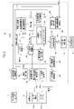
- FIG. 1 is a schematic diagram schematically showing the configuration of main parts of an internal combustion engine including a control device (ECU) according to one embodiment of the present invention
- FIG. 2 is a block diagram showing the main configuration of an ECU of the internal combustion engine of FIG. 1
- FIG. 3 is a flowchart showing excess ratio calculation processing for calculating an excess air ratio by an excess ratio calculation unit in the ECU of FIG. 2
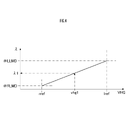
- FIG. 4 is a graph showing how an excess air ratio in a stoichiometric region is calculated in the process of FIG. 3.
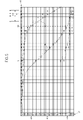
- FIG. 4 is a diagram showing a graph corresponding to a lookup table for obtaining a lean side threshold value LREF and a rich side threshold value RREF and a data map for calculating an excess air ratio in the process of FIG. 3;
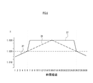
- FIG. 4 is a graph schematically showing how an excess air ratio ⁇ calculated by the process of FIG. 3 changes;
- FIG. 5 is a waveform diagram showing voltage waveforms representing changes in voltage values output by a voltage calculator over time obtained while driving a vehicle equipped with an internal combustion engine.
- 3 is a diagram showing an example of inspection by a characteristic inspection unit and calibration by a calibration unit in the ECU of FIG. 2;
- FIG. FIG. 5 is a diagram showing another example of inspection by the characteristic inspection unit and calibration by the calibration unit;
- FIG. 5 is a diagram showing another example of inspection by the characteristic inspection unit and calibration by the calibration unit;
- FIG. 9 is a diagram showing still another example of inspection by the characteristic inspection unit and calibration by the calibration unit;
- FIG. 1 shows the configuration of the main parts of a four-cycle internal combustion engine provided with an internal combustion engine control system according to an embodiment of the present invention.
- This control device for an internal combustion engine has a function of performing air-fuel ratio feedback control based on the deviation between the excess air ratio obtained based on the oxygen concentration in the exhaust gas of the internal combustion engine and a target excess air ratio.
- an engine body 1 of this internal combustion engine includes an intake pipe 2 provided at an intake port, and an air cleaner 4 provided in the intake pipe 2 and supplied from an air cleaner 4 to the intake port. and a throttle valve 3 that adjusts according to
- the throttle valve 3 is provided with a throttle sensor 5 that detects the opening degree of the throttle valve 3 .
- a fuel injection valve 6 for injecting fuel is provided near the intake port of the intake pipe 2 . Fuel is pressure-fed from a fuel tank (not shown) to the fuel injection valve 6 by a fuel pump.
- the intake pipe 2 is provided with an intake pressure sensor 7 that detects the intake pressure in the intake pipe 2 and an intake air temperature sensor 8 that detects the temperature of the intake air in the intake pipe 2 .
- An exhaust pipe 10 connected to an exhaust port of the engine body 1 is provided with a catalyst 11 for reducing unburned components in the exhaust of the exhaust pipe 10 and an oxygen sensor 12 for detecting the oxygen concentration in the exhaust.
- a spark plug 13 connected to an ignition device 14 is fixed to the engine body 1 .
- an ECU (electronic control unit) 15 as a control device issues an ignition timing command to an ignition device 14 , spark discharge occurs in a cylinder combustion chamber of the engine body 1 .
- the ECU 15 receives analog voltages indicating detection values of the throttle sensor 5, the intake pressure sensor 7, the intake air temperature sensor 8, the oxygen sensor 12, the cooling water temperature sensor 17, and the atmospheric pressure sensor 20 for detecting the atmospheric pressure. .
- the fuel injection valve 6 is also connected to the ECU 15 .
- a signal indicating the rotation angle position of the crankshaft 18 from the crank angle sensor 19 is also input to the ECU 15 . That is, the crank angle sensor 19 has a plurality of projections arranged at intervals of a predetermined angle (for example, 15 degrees) on the outer circumference of the rotor 19a that rotates in conjunction with the crankshaft 18, near the outer circumference of the rotor 19a. It is magnetically or optically detected by the pickup 19b, and a pulse (crank signal) is generated from the pickup 19b each time the crankshaft 18 rotates by a predetermined angle.
- a predetermined angle for example, 15 degrees
- FIG. 2 shows the main configuration of the ECU 15.
- the oxygen sensor 12 which supplies the detection signal of the oxygen concentration in the exhaust gas to the ECU 15 is an oxygen sensor in high-temperature exhaust gas, and is provided so as to be in contact with the exhaust gas of an internal combustion engine having exhaust pulsation. It has a sensor element 12a as a detection section for detecting the oxygen concentration inside, and a sensor heater 12b as a heater section for heating the sensor element 12a adjacent to the sensor element 12a.
- the sensor element 12a has a resistance value that changes substantially stepwise when the oxygen concentration of the exhaust gas from the internal combustion engine is in the vicinity of the stoichiometric. It presents a pulse waveform with a crest value corresponding to .
- a titania oxygen sensor which is a resistive oxygen sensor whose resistance value changes according to the oxygen concentration, is used.
- the ECU 15 includes a heater heat generation control section 22 that controls the sensor heater 12b, a temperature calculation section 23 that calculates a temperature value T indicating the temperature of the sensor element 12a, and an output signal from the sensor element 12a that indicates the oxygen concentration in the exhaust gas. and a voltage calculator 24 for converting to a voltage value VHG as a detected value.
- the control of the temperature of the sensor heater 12b by the heater heat generation control unit 22 is performed by pulse width modulation (PWM) control by the ECU 15 of the amount of current I supplied to the sensor heater 12b from a power source (storage battery) (not shown).
- the temperature calculation unit 23 includes a heater temperature reading unit 23a that obtains the temperature of the sensor heater 12b based on the resistance value of the sensor heater 12b, and a detection unit temperature estimation unit that obtains the temperature of the sensor element 12a based on the temperature of the sensor heater 12b. 23b.
- the temperature calculation unit 23 calculates the temperature value T by, for example, reading each value of the heater voltage applied to the sensor heater 12b and the energized current amount I to obtain the resistance value of the sensor heater 12b.
- the temperature reading section 23a obtains the temperature of the sensor heater 12b
- the detection section temperature estimating section 23b obtains the temperature T of the sensor element 12a based on the obtained temperature.
- Acquisition of the temperature T by the detector temperature estimator 23b is performed by converting the temperature of the sensor heater 12b into the temperature T using table data or a calculation formula showing the correspondence relationship between the temperature T prepared in advance in the ECU 15 and the temperature of the sensor heater 12b. It is done by The calculation results of the temperature calculation unit 23 and the voltage calculation unit 24 are supplied to the substitute value calculation unit 26 of the excess ratio calculation unit 25, which will be described later.
- the ECU 15 also includes a rotation speed calculation unit 27 that calculates the rotation speed NE and the angular speed NETC of the internal combustion engine based on the detection result of the crank angle sensor 19, a temperature value T from the temperature calculation unit 23, and a temperature value T from the voltage calculation unit 24. and an excess air ratio calculation unit 25 for calculating an excess air ratio ⁇ based on the voltage value VHG and the angular velocity NETC from the rotation speed calculation unit 27 .
- the ECU 15 includes a target value calculating section 28 as a target value setting section for calculating an excess air ratio ⁇ cmd as a control target value based on an estimated value of the amount of oxygen stored in the catalyst 11 and the operating state of the internal combustion engine, and a rotational speed
- the basic injection amount calculation unit 29 calculates the basic injection amount BJ based on the rotation speed NE from the calculation unit 27 and the pressure PM in the intake pipe 2 from the intake pressure sensor 7, and the excess ratio calculation unit 25.
- An injection amount calculation unit 31 that calculates an injection amount Ti based on the basic injection amount BJ and operates the fuel injection valve 6 is provided.
- the feedback coefficient calculation unit 30 performs PID control based on the deviation between the excess air ratio ⁇ and the target excess air ratio ⁇ cmd to calculate the feedback coefficient k. Based on the injection amount Ti calculated by the injection amount calculator 31 based on the feedback coefficient k and the basic injection amount BJ, the fuel injection valve 6 is opened for a period of time corresponding to this. Thus, an amount of fuel is injected into the cylinder combustion chamber of the engine body 1 according to the feedback coefficient k of the PID control based on the comparison between the excess air ratio ⁇ and the target excess air ratio ⁇ cmd.
- the excess ratio calculation unit 25 linearizes the voltage value VHG with respect to the excess air ratio while compensating for the temperature characteristics.
- the excess air ratio ⁇ of the exhaust gas is calculated using the data LD. However, as will be described later, this calculation is applied when the voltage value VHG is equal to or less than the lean side threshold value LREF, and when the voltage value VHG is greater than the lean side threshold value LREF, the excess air ratio ⁇ is obtained by another method.
- the excess ratio calculation unit 25 includes a torque calculation unit 32 that calculates a torque value TQ of the internal combustion engine based on the crank angular speed NETC of the internal combustion engine, and a limit threshold setting unit 33 that sets a conversion limit threshold for the linearization conversion described above. , a storage unit 34 for storing data necessary to calculate an alternative value R of the excess air ratio ⁇ , a data map and a lookup table to be described later, and an alternative value calculation unit 26 for calculating the alternative value R.
- the limit threshold setting unit 33 sets a lean side threshold LREF as a lean side conversion limit threshold and a rich side threshold RREF as a rich side conversion limit threshold for the voltage value VHG from the voltage calculation unit 24. set.
- a lean side threshold LREF as a lean side conversion limit threshold
- a rich side threshold RREF as a rich side conversion limit threshold for the voltage value VHG from the voltage calculation unit 24. set.
- FIG. 5 shows a first scale value G1 in the horizontal direction in FIG.
- a data map having a second scale value G2 in the vertical direction and having a plurality of numerical values of the data LD associated with the voltage value VHG and the temperature value T as coordinates is set.
- each example of the lookup table corresponding to the graphs 35 and 36 for obtaining the lean side threshold value LREF and the rich side threshold value RREF is superimposed on the data map.
- the data map associates a plurality of excess air ratio values with a plurality of first scaled values G1 for the temperature value T and a plurality of second scaled values G2 for the voltage value VHG (detected value).
- the lookup table shows the correspondence between the rich side threshold value RREF and the lean side threshold value LREF for determining which air-fuel ratio region the voltage value VHG corresponds to: the rich region, the stoichiometric region, or the lean region, with the first scale value G1. They are shown in relation to each other.
- Graph 35 shows points on the above data map with coordinates of voltage value VHG and temperature value T, for example, where the excess air ratio ⁇ as the boundary between the lean region and the stoichiometric region is 1.02. It is a graph obtained by obtaining a plurality of points and connecting these points by linear interpolation. Further, the graph 36 shows, for example, the excess air ratio ⁇ as the boundary between the stoichiometric region and the rich region is 0.98, and the voltage value VHG and the temperature value T corresponding to this value are set as coordinates on the above data map. It is a graph obtained by obtaining points and connecting each of these points by linear interpolation.
- the limit threshold value setting unit 33 sets the voltage value v0 derived from the coordinate t0 as the lean region and the stoichiometric value. It can be set as a lean-side threshold value LREF for the boundary with the region.
- the voltage value v1 derived from the coordinate t0 is applied to the boundary between the stoichiometric region and the rich region. It can be set as the rich side threshold value RREF.
- the storage unit 34 stores, as data necessary for calculating the substitute value R, an execution time Ti1 of fuel injection by the fuel injection valve 6, a torque value TQ1 stores excess air ratio ⁇ b with respect to conversion limit threshold LREF.
- the excess ratio calculation unit 25 substitutes the substitute value R for the exhaust air ratio instead of the excess air ratio ⁇ as the linearized data LD.
- FIG. 3 shows excess ratio (lambda) calculation processing for calculating the excess air ratio ⁇ in the excess ratio calculation unit 25 .
- the control by the ECU 15 including this excess ratio calculation process is executed in synchronization with the stroke of the internal combustion engine based on the pulse signal indicating the rotation angle position of the crankshaft 18 from the crank angle sensor 19 .
- the torque TQ of the internal combustion engine is calculated by the torque calculation unit 32 based on the crank angular speed NETC from the rotational speed calculation unit 27 in step S1.
- step S2 based on the temperature value T from the temperature calculation unit 23, the limit threshold value setting unit 33 uses lookup tables corresponding to the graphs 35 and 36 of FIG. Set the threshold RREF.
- step S3 the voltage value VHG is obtained from the voltage calculation unit 24, the voltage value VHG is corrected by the deviation VD obtained by the voltage difference confirmation unit 43 described later, and the control voltage value (detection value) is obtained.
- the control voltage value (detection value) is obtained.
- step S4 the above data map (FIG. 5) is scanned based on the temperature value T acquired in step S2 and the voltage value VHGcon acquired in step S3, and thus the value of the voltage value VHGcon is compared with its temperature characteristics.
- Data LD linearized and converted to the excess air ratio ⁇ with compensation is obtained.
- step S5 it is determined whether or not the voltage value VHGcon obtained in step S3 is smaller than the rich side threshold value RREF set in step S2. If it is determined to be smaller, the process proceeds to step S16 while setting the flag F_DETECT to zero in the following step S6, sets the value of the data LD as the excess air ratio ⁇ value LAMBDA, and ends the excess ratio calculation process of FIG. do.
- step S7 the voltage value VHGcon acquired in step S3 is larger than the lean side threshold value LREF set in step S2. Determine whether or not
- the excess air ratio ⁇ as the linearized converted data LD in step S8 is obtained by presetting the excess air ratio ⁇ as the boundary between the predetermined stoichiometric region and the lean region.
- a variable #LLMD for example, 1.02
- a variable #RLMD for example, 0.98 that can preset the excess air ratio ⁇ as the boundary between the predetermined rich region and the stoichiometric region. If there is, it can be represented by a graph as shown in FIG. In FIG. 4, the horizontal axis in the horizontal direction of the graph is the voltage value VHG, and the vertical axis in the vertical direction in FIG. 4 is the excess air ratio ⁇ .
- ⁇ 1 (((vhg1-rref) ⁇ (lref-rref)) ⁇ (#LLMD-#RLMD))+#RLMD (2)
- step S9 the execution time Ti of the last fuel injection by the fuel injection valve 6, the torque TQ calculated in step S1 are set to Ti1 and TQ1, respectively, and the excess air ratio ⁇ related to the lean side threshold value LREF is stored in the storage unit 34 as ⁇ b. .
- the countdown timer value TIMER indicating the valid time of the memory is reset to its predetermined initial value #TMINT.
- the flag F_DETECT is set to 1 and the process proceeds to step S16, where the value of the data LD obtained in step S8 is set as the air ratio excess ratio ⁇ value LAMBDA, and the excess ratio calculation process of FIG. 3 ends.
- the value of the data LD obtained in step S8 is stored as ⁇ b.
- the exponential moving average ⁇ a of the excess air ratio ⁇ (data LD) obtained by the following equation (3) is stored as ⁇ b.
- ⁇ a LD ⁇ k1+ ⁇ ab ⁇ (1 ⁇ k1) (3)
- k1 is the moving average coefficient
- ⁇ ab is the moving average value in the previous control cycle stored in the storage unit 34.
- 0.34 is used as the moving average coefficient k1.
- the storage unit 34 preferably stores moving average values as the fuel injection execution time Ti1 and the torque value TQ1.
- the exponential moving average TiFLT of the fuel injection execution time Ti is obtained by the following equation (4) and stored as Ti1
- TQFLT TQ ⁇ k3+TQFLTb ⁇ (1 ⁇ k3) (5)
- k2 and k3 are moving average coefficients
- TiFLTb and TQFLTb are moving average values stored in the storage unit 34 in the previous control cycle.
- different values can be used for moving average coefficients k1, k2, and k3.
- step S10 when it is determined in step S7 that the voltage value VHGcon acquired in step S3 is larger than the lean side threshold value LREF, in step S10, it is determined whether or not the countdown timer value TIMER has reached zero. judge. Then, if TIMER has reached zero, the flag F_DETECT is reset to 0 (step S11).
- the substitute value R is calculated by the above equation (1), and the value of the data LD is set as the substitute value R.
- step S14 it is determined whether or not the value of data LD set in step S13 is greater than a predetermined upper limit #LLMT. If the value of the data LD set in step S13 is greater than the upper limit #LLMT, the value of the data LD is set to the upper limit #LLMT (step S15). In this case, 1.25, for example, can be used as the upper limit #LLMT.
- step S13 or step S15 the value of the data LD set in step S13 or step S15 is set as the excess air ratio ⁇ value LAMBDA (step S16), thereby ending the excess ratio calculation process of FIG.
- the ECU 15 converts the excess air ratio ⁇ value LAMBDA calculated in the excess ratio calculation process of FIG.
- the amount of fuel injected by the fuel injection valve 6 is controlled by the PID control of the feedback coefficient calculator 30 so as to match the rate ⁇ cmd.
- FIG. 6 is a graph schematically showing how the excess air ratio ⁇ value LAMBDA calculated by the excess ratio calculation process of FIG. 3 changes.
- the horizontal axis of the graph is numerical values indicating the passage of time, and the vertical axis is the excess air ratio ⁇ .
- Graph 37 in FIG. 6 gradually increases the actual exhaust air excess ratio ⁇ at a constant change rate in the range from the left end side to the vicinity of the center of the horizontal axis in the left-right direction in FIG. In the range from near the center of the horizontal axis to the right end, when the actual excess air ratio ⁇ of the exhaust gas is gradually decreased at a constant rate of change, the voltage value VHG read by the voltage calculation unit 24 of the ECU 15 is calculated. 3 shows the numerical change in the excess air factor ⁇ value when the excess air factor ⁇ value is calculated using the data obtained by directly linearizing the excess air factor ⁇ while compensating for the temperature characteristic.
- the graph 38 shows that the voltage value VHG from the voltage calculation unit 24 is lean when the actual exhaust air excess ratio ⁇ is gradually increased or decreased at a constant change rate from the left end to the right end of the horizontal axis.
- the excess air ratio ⁇ value is calculated using the data obtained by directly linearizing the voltage value VHG using the data map (FIG. 5) or formula (2) described above.
- the voltage value VHG from the voltage calculation unit 24 exceeds the voltage value lref (corresponding to the excess air ratio ⁇ of 1.020) of the lean threshold value LREF, the voltage value VHG is linearized.
- the alternative value R obtained by the above formula (1) instead of the converted data is used as the value of the excess air ratio ⁇ , the change in the value of the excess air ratio ⁇ is shown.
- the excess air ratio ⁇ is calculated using the above linearized converted data, and the voltage value VHG exceeds the lean side threshold value LREF.
- the excess air ratio calculation unit 25 interlocks with the actual excess air ratio ⁇ of the exhaust over the entire range of the graph in FIG. It can be seen that the proportionally changing excess air ratio ⁇ value can be supplied to the feedback coefficient calculator 30 . As a result, interruption of the PID control by the feedback coefficient calculator 30 is suppressed.
- the excess ratio calculation unit 25 includes a characteristic inspection unit 40 that inspects the characteristics of the voltage value VHG (detected value) that changes according to the variation in the resistance value, and the data map and lookup unit 40 based on the inspection result. and a calibrating unit 41 for calibrating the up-table.
- the characteristic inspection unit 40 includes a temperature difference confirmation unit 42 that confirms the deviation amount TD of the temperature T from the reference value and sets the temperature Tcon for control, and an average value VHGSTD of the voltage value VHG of the sensor element 12a within a predetermined time. and a voltage difference confirmation unit 43 that confirms the deviation VD between the lean side threshold value LREF and sets the control voltage value (detected value) VHGcon, and the set control temperature Tcon and the control voltage value ( The output characteristic of the oxygen sensor 12 connected to the ECU 15 is checked according to the detected value (VHGcon).
- the temperature Tcon for control is set to be the same as the engine temperature and intake air temperature at room temperature and before starting.
- the temperature difference confirming unit 42 substantially translates the lookup table corresponding to the data map and the graphs 35 and 36 in the horizontal direction (direction of the first scale value G1) in FIG. .
- the wave height of the voltage value VHG becomes almost zero (a state in which the voltage value VHG does not move) and the standard resistance value has the same value as the graphs 35 and 36 (the voltage value VHGref and the graphs 35 and 36 overlap).
- the standard voltage value VHGref becomes equal to the graph 35 (lean side threshold value LREF).
- the value can be obtained by scanning the lookup table corresponding to graph 35 at the sufficiently low temperature Tcon.
- the average value VHGSTD can be obtained, for example, from the arithmetic average value of the voltage values VHG read many times in a period of 5 seconds, thereby reducing the influence of quantization errors in reading the voltage values VHG. , the deviation VD can be obtained, and the voltage value VHGcon for control can be set with high accuracy.
- control voltage value (detected value) VHGcon is corrected to be the same as the graph 35 (lean side threshold value LREF) when the control temperature Tcon is equal to or lower than the predetermined value.
- the voltage difference confirming unit 43 substantially translates the data map in the vertical direction (direction of the second scale value G2) in FIG.
- the characteristic inspection unit 40 sets the target excess air ratio ⁇ cmd to the vicinity of the stoichiometric value through the target value calculation unit 28, acquires the peak value of the voltage value VHGcon, It is checked whether this peak value corresponds to any of the air-fuel ratio regions.
- the lookup tables corresponding to the data map and the graphs 35 and 36 are calibrated based on the result of the inspection.
- FIG. 7 shows the voltage obtained while driving the vehicle equipped with the oxygen sensor 12 having a standard resistance value in the internal combustion engine with the target excess air ratio ⁇ cmd set to the vicinity of the stoichiometric by the characteristic inspection unit 40.
- a voltage waveform 44 representing a change over time is shown for the value (detected value) VHGref.
- FIG. 7 also shows an air-fuel ratio waveform 45 representing the waveform of the output signal of a wideband air-fuel ratio sensor provided temporarily for verification purposes.
- the exhaust gas in the exhaust pipe and the oxygen concentration contained in the exhaust gas are pulsating, so as shown in FIG.
- the voltage waveform 44 of the voltage value (detected value) VHGref and the air-fuel ratio waveform 45 of the air-fuel ratio sensor provided side by side are observed as waveforms having wave heights that oscillate with the passage of time.
- the resistance value of the sensor element 12a originally changes steeply in a stepwise manner at the oxygen concentration near the stoichiometric.
- the wave height M of the voltage waveform 44 (peak value of the detected value) is observed as a waveform that oscillates much more than the wave height of the air-fuel ratio waveform 45 in the same period P.
- Lookup tables corresponding to the graph 36 (rich side threshold value RREF) and the graph 35 (lean side threshold value LREF) are respectively set so as to follow the wave height transition of the voltage waveform 44 that oscillates greatly.
- the rich peak near the lower rich threshold RREF in FIG. Many of 46 are located approximately on the rich side threshold RREF, while many of the lean peaks 47 near the upper lean side threshold LREF in FIG. 7 are located approximately on the lean side threshold LREF.
- the voltage value of the oxygen sensor 12 actually connected to the ECU 15 is set while performing feedback control of the air-fuel ratio so as to reproduce the state of the illustrated period P by setting the target excess air ratio ⁇ cmd near the stoichiometric.
- Detected value The wave height M expressed by VHGcon is measured by the ECU 15, and the peak of the wave height M is checked to see if it matches the lean side threshold value LREF and the rich side threshold value RREF. It is possible to grasp and acquire how much the characteristic deviation of the voltage value VHGcon from the characteristic of the voltage value VHGref at a constant resistance value is.
- the characteristic inspection unit 40 sets the target excess air ratio ⁇ cmd to the vicinity of the stoichiometric and performs the air-fuel ratio feedback control while checking the wave height of the voltage value (detection value) VHGcon of the oxygen sensor 12 connected to the ECU 15. It is configured to obtain a peak value of M and check whether the peak value of the wave height M falls within a rich region, a stoichiometric region, or a lean region. Further, based on this inspection result, the calibration unit 41 performs affine transformation so that the peak value of the wave height M conforms to the rich side threshold value RREF and the lean side threshold value LREF, and performs the data map and the lookup table. can be calibrated.
- the calibration unit 41 expands or contracts the plurality of first scale values G1 and the plurality of second scale values G2 in the manner of so-called affine transformation, thereby calibrating the data map and the lookup table.
- a first calibrated magnification value C1 and a second calibrated magnification value C2 are provided.
- the calibration unit 41 calculates the lean side peak value 47v of the control voltage value VHGcon that changes over time and the graph 35 (lean side threshold value LREF). , for example, if the lean-side peak value 47v is in the lean region, the first calibration magnification value C1 is increased, and the data map and lookup table are shifted to the right side in FIG. 8A. When the lean side peak value 47v is in the stoichiometric region, the first calibrated magnification value C1 is decreased to shrink the data map and lookup table leftward in FIG. 8B.
- the calibrating unit 41 multiplies the first scale value G1 of the data map and lookup table by the increased or decreased first calibration magnification value C1, so that the data map and lookup table are substantially converted in the manner of so-called affine transformation.
- 0 Kelvin minus 273.15 degC; absolute zero
- the calibration unit 41 compares the rich-side peak value 46v of the control voltage value VHGcon that changes over time with the lookup table corresponding to the graph 36 (rich-side threshold value RREF), For example, when the rich side peak value 46v is in the rich region, the second calibration magnification value C2 is increased to expand the data map and lookup table downward in FIG. is in the stoichiometric region, the second calibrated scale factor value C2 is decreased to shrink the data map and lookup table upward in FIG. 8C.
- the calibrating unit 41 multiplies the second scale value G2 of the data map and lookup table by the increased or decreased second calibration magnification value C2, so that the data map and lookup table are substantially converted in the manner of so-called affine transformation. calibrate by expanding or contracting It should be noted that the value of the graph 35 (lean-side threshold value LREF) when the above-described control temperature Tcon is equal to or lower than a predetermined value can be adopted as the scaling origin of the second scale value G2.
- the first calibrated magnification value C1 and the second calibrated magnification value C2 when the first calibrated magnification value C1 and the second calibrated magnification value C2 are increased or decreased, the first calibrated magnification value C1 or the first calibrated magnification value C1 or The calibration unit 41 can be configured to include a transition process of gradually increasing or decreasing the second calibration magnification value C2 to gradually transition to the calibration completed state.
- the stoichiometric amplitude (stoichiometric amplitude (wave height)) of the oxygen sensor 12 changes according to the actual temperature of the sensor element 12a, and the amplitude changes.
- the oxygen sensor 12 has a characteristic of a stoichiometric amplitude of 4 volts when the temperature value measured as accurately as possible when new is 600 degC
- the sensor heater 12 b undergoes thermal deterioration (oxidation) during the long-term use process. occurs and the resistance value of the sensor heater 12b increases, the temperature of the sensor heater 12b and the temperature T of the sensor element 12a, which are obtained by reading the resistance value of the sensor heater 12b, appear to be the actual values including errors. It shows a value different from the temperature.
- the characteristic inspection unit 40 the stoichiometric amplitude characteristic of the oxygen sensor 12 changes along with the actual temperature of the sensor element 12a. , the stoichiometric amplitude will be observed as 4 volts.
- the correspondence relationship between the apparent temperature of the sensor heater 12b and the temperature T of the sensor element 12a and the stoichiometric amplitude is shifted by about +50 degC compared to when the sensor heater 12b is new and not thermally deteriorated. Observed.
- the temperature T of the sensor heater 12b obtained by reading from the resistance value of the sensor heater 12b is the actual temperature of the sensor element 12a. It is possible to accurately grasp the degree of temperature error with respect to the value. Further, when the temperature error is large, it can be determined that the sensor heater 12b has deteriorated.
- a plurality of excess air ratio values are set to a plurality of first scale values G1 for the temperature T of the sensor heater 12b and a plurality of values for the voltage value VHG.
- the above-mentioned data map showing correspondence with a plurality of second scale values G2, and the rich side for determining which air-fuel ratio region the voltage value VHG corresponds to: the rich region, the stoichiometric region, or the lean region
- the above-mentioned lookup table showing the threshold value and the lean side threshold value in correspondence with the first scale value G1 is used.
- the above-described characteristic checking unit 40 checks to which of the air-fuel ratio regions the peak of the read wave peak value corresponds, and based on the result of this check, , and derive the temperature calibration coefficient K (first calibration magnification value C1) for correcting the first scale value G1 and calibrating the above correspondence relationship, the calibration unit 41 described above is used.
- the deterioration judgment unit 48 judges that the sensor heater 12b is deteriorated.
- the deterioration determination unit 48 acquires the initial value of the temperature calibration coefficient K when the calibration unit 41 performs calibration in the initial stage or when the OBD diagnosis machine, which will be described later, issues a reset command. Each time the latest value of is acquired, the absolute value of the difference between the initial value and the latest value is compared with a predetermined deterioration judgment value, and if the absolute value exceeds the deterioration judgment value, the sensor heater 12b is deteriorated. I judge.
- the deterioration determining unit 48 sets a state flag F indicating whether or not the initial value of the temperature calibration coefficient K, which will be described later, has been set, for example, by a bit (single-digit binary number). is set to "1" indicating that the temperature calibration coefficient K has been changed, thereby prohibiting subsequent changes to the initial value of the temperature calibration coefficient K. Even after the state flag F is set to "1" in this way, the latest value of the temperature calibration coefficient K is updated by the calibration unit 41 as the resistance value or temperature value changes over time due to deterioration of the sensor heater 12b.
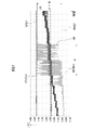
- the latest value of the temperature correction coefficient K deviates from the initial value (line B) of the temperature calibration coefficient K as indicated by lines C and D in FIG. 5, for example. become.
- the deterioration determining unit 48 determines that the difference between the initial value of the temperature calibration coefficient K related to the first scale value G1 indicated by the line B and the latest value of the temperature calibration coefficient K indicated by the line C or D is the above deterioration. If the distance exceeds the determination value, it can be determined that the sensor heater 12b has deteriorated.
- the deterioration determination value is 0.3
- the initial value of the temperature calibration coefficient K for the line B is 1.02
- the latest value of the temperature calibration coefficient K for the line C is 0.935
- the temperature The difference between the initial value and the latest value of the calibration coefficient K is 0.085, which in this case is smaller than the deterioration determination threshold value of 0.3, so it is determined that there is no deterioration.
- the deterioration determination value is 0.3
- the initial value of the temperature calibration coefficient K for the line B is 1.03
- the latest value of the temperature calibration coefficient K for the line D is 1.35
- the difference between the initial value and the latest value of the temperature calibration coefficient K is 0.32. In this case, it is determined that the sensor heater 12b is deteriorated because it is larger than the deterioration determination threshold value of 0.3.
- the deterioration determination unit 48 includes a flag storage unit 49 that stores the state flag F in order to set the initial value of the temperature calibration coefficient K appropriately.
- the flag storage unit 49 is formed of, for example, a rewritable non-volatile memory capable of holding data without power supply to the storage unit.
- the deterioration determination unit 48 determines the initial value of the temperature calibration coefficient K and the temperature calibration coefficient An initial value for the temperature calibration factor K can be set because the most recent value of K is set to the same value (zero difference). That is, it functions as a so-called initializer for the temperature calibration coefficient K, and the initial value of the temperature calibration coefficient K is appropriately set from the latest value of the temperature calibration coefficient K calibrated by the calibration unit 41 .
- the deterioration determination unit 48 determines that the initial value of the temperature calibration coefficient K has been obtained properly based on the result of the inspection by the characteristic inspection unit 40, the deterioration determination unit 48 sets the state flag F to Set to a value indicating that it has been set.
- the calibration in the calibration unit 41 is not so-called one-shot learning based on instantaneous observation, but integrally performed by repeatedly increasing and decreasing the gradually derived temperature calibration coefficient K as described above.
- the deterioration determining unit 48 sets the state flag F to the ON state of "1 ” to prohibit subsequent changes to the initial value of the temperature calibration coefficient K.
- the initial value of the temperature calibration coefficient K derived by the deterioration determination unit 48 is a value with excellent reproducibility.
- the latest value of the temperature calibration coefficient K, the initial value of the temperature calibration coefficient K, and the state flag F may be rewritten to desired values by commands from an external terminal device.
- the temperature calibration coefficient K and the state flag F are rewritten by an operation via an OBD diagnostic machine as an external terminal device.
- an OBD diagnosis machine is operated to activate the learning value reset command of the ECU 15, and the latest value of the temperature calibration coefficient K and the initial value It is necessary to cancel the determination by the deterioration determination unit 48 that the sensor heater 12b is deteriorated by initializing each parameter such as the value and the state flag F.
- the ECU 15 can cooperate with an external terminal device.
- the wave height (fluctuation) of the voltage value VHG from the sensor element 12a changes according to the actual temperature (real value) of the sensor element 12a.
- the characteristic checking unit 40 checks whether the sensor It is necessary to control the temperature of the heater 12b to an appropriate temperature. That is, if the temperature of the sensor heater 12b is too cold or too hot, proper inspection cannot be performed.
- the ECU 15 further includes a heater control temperature deriving section that obtains the temperature Tc for controlling the heater heat generation control section 22 by multiplying the temperature T of the sensor element 12a by the reciprocal of the temperature calibration coefficient K. 50 is provided, and the heater heat generation control unit 22 causes the sensor heater 12b to generate heat so that the temperature Tc becomes the target temperature Ttrg.
- the heater heat generation control unit 22 applies a voltage pulse width modulated according to the difference between this temperature Tc and the target temperature Ttrg to cause the sensor heater 12b to generate heat.
- the inspection by the characteristic inspection unit 40 is properly performed, and thus the presence or absence of deterioration of the sensor heater 12b is properly determined.
- the target temperature value Ttrg is not limited to a constant value, and may be set so as to vibrate in conjunction with the calibrating unit 41 . That is, the temperature calibration coefficient K can be derived by learning at multiple points while changing the temperature conditions.
- the absolute value of the difference between the initial value of the temperature calibration coefficient K and the latest value of the temperature calibration coefficient K obtained by the calibration unit 41 is greater than the predetermined deterioration determination value is provided with a deterioration judgment unit 48 for judging that the sensor heater 12b is deteriorated.
- An additional temperature sensor for measuring the actual temperature of the sensor heater 12b may not be required.
- the deterioration determination unit 48 sets the initial value of the temperature calibration coefficient K to the same value as the latest value, and the state When the flag F indicates that the initial value of the temperature calibration coefficient K has been set, subsequent changes to the initial value of the temperature calibration coefficient K are prohibited. The value allows to set the initial value of the temperature calibration factor K.
- the state flag F of the flag storage unit 49 which is a nonvolatile memory, is set to "1" (on state). Therefore, after it is determined that the latest value of the temperature calibration coefficient K has reached a saturated state and the state of the heater section has been appropriately captured, the state flag F can be continuously held in the ON state. Also, the properly obtained initial value of the temperature calibration coefficient K can be maintained at a value with excellent reproducibility.
- the deterioration determination unit 48 can rewrite the latest value of the temperature calibration coefficient K, the initial value of the temperature calibration coefficient K, and the state flag F to desired values in response to a command from an external terminal device.
- the deteriorated oxygen sensor 12 is replaced with a new one during maintenance of an automobile in use, it is found that the sensor heater 12b in use is deteriorated through an operation via an OBD diagnosis device as an external terminal device. Judgment etc. can be canceled.
- the sensor heater 12b is caused to generate heat by the heater heat generation control unit 22 according to the difference between the temperature Tc obtained by the heater control temperature deriving unit 50 and the target temperature Ttrg.
- the inspection by the unit 40 can be performed appropriately, and the presence or absence of deterioration of the sensor heater 12b can be determined appropriately.
- the data map and the lookup table are substantially transformed in the manner of so-called affine transformation by multiplying the plurality of first scale values G1 of the data map and the lookup table by the first calibration magnification value C1.
- the calibration is performed by expanding or contracting the image (equation (6a))
- the present invention is not limited to this.
- the data map and lookup table can be substantially enlarged or reduced even with a configuration in which the temperature for control for scanning the data map and lookup table is multiplied by the first calibrated magnification value C1.
- the peak value of the actually measured voltage value (detection value) VHGcon matches the rich side and lean side thresholds (the peak of the wave height is It is possible to calibrate so that it overlaps with the threshold value), calculate an accurate excess air ratio, and perform appropriate air-fuel ratio feedback control. Further, it is possible to appropriately determine whether or not the sensor heater 12b is deteriorated while appropriately performing inspection by the characteristic inspection unit 40.
- FIG. 1 the peak value of the actually measured voltage value (detection value) VHGcon matches the rich side and lean side thresholds (the peak of the wave height is It is possible to calibrate so that it overlaps with the threshold value), calculate an accurate excess air ratio, and perform appropriate air-fuel ratio feedback control. Further, it is possible to appropriately determine whether or not the sensor heater 12b is deteriorated while appropriately performing inspection by the characteristic inspection unit 40.
- the reference value Tref for setting the temperature Tcon may be calculated from only one.
Landscapes
- Engineering & Computer Science (AREA)
- Chemical & Material Sciences (AREA)
- Combustion & Propulsion (AREA)
- Mechanical Engineering (AREA)
- General Engineering & Computer Science (AREA)
- Combined Controls Of Internal Combustion Engines (AREA)
Abstract
低コストでかつ極力制約のないタイミングでヒータ部の劣化の有無を判定できる内燃機関の制御装置を提供する。 ECU(15)は、酸素センサ(12)からの電圧値VHGが何れの空燃比領域に該当するかを判別するためのリッチ側、リーン側閾値をセンサヒータ(12b)の温度Tを示す第1目盛値G1と対応付けたルックアップテーブルと、電圧VHGの尖頭(46、47)が何れの空燃比領域に該当するかを点検する特性点検部(40)と、この点検結果に基づいて、第1目盛値G1補正用の温度較正係数Kを導出する較正部(41)と、温度較正係数Kの初期値と最新値との差が劣化判定値よりも大きい場合に、センサヒータ(12b)が劣化していると判定する劣化判定部(48)とを有する。
Description
本発明は、内燃機関の高温排気ガス内酸素センサにおけるヒータ部の劣化の有無を判定する機能を有する内燃機関の制御装置に関する。
従来、抵抗加熱を利用したヒータの劣化を検出する装置が知られている(例えば、特許文献1、2参照)。特許文献1の装置では、ヒータの温度を検出するために配備された温度検出用のセンサ及び温度検出器と、ヒータに印加された電圧を検出するための電圧検出器とを用いてヒータの実際の温度と抵抗を計測し、計測した温度と抵抗とから抵抗温度係数を導出し、導出した抵抗温度係数の既定値からの逸脱の程度が一定の限度(閾値)を超えたとき、ヒータ部が劣化したと判定される。
特許文献2の装置では、内燃機関の排気ガス中の酸素濃度に応じた電圧を示す電気信号を出力するセンサ素子と、センサ素子を活性化温度以上の温度になるように加熱するヒータ素子とを有する酸素濃度検出器について、ヒータ素子の劣化の有無が判定される。この判定は、ヒータ素子及び排気ガスの一方又は双方により加熱されて昇温したセンサ素子の温度が酸素濃度検出器の雰囲気温度に収束するに足る所定時間が経過した場合に、ヒータ素子の抵抗値と所定の閾値との大小関係に基づいて行われる。
しかしながら、上記特許文献1の装置によれば、ヒータの実際の温度を検出するためにヒータに温度検出用のセンサを設ける必要があるので、その分だけ装置のコストが高くなる。
また、上記特許文献2の装置によれば、ヒータ素子に温度検出用のセンサを設ける必要はないが、センサ素子の温度が酸素濃度検出器の雰囲気温度(外気温度)にほぼ収束するまで長時間、例えば一晩(8時間)車両をエンジン停止状態にして待ってから劣化有無の判定を行う必要がある。このため、ヒータ素子の劣化有無を判定できるタイミングがかなり限定され、かつこのタイミングが得られるまでに長時間を要する。
本発明の目的は、かかる従来技術の問題点に鑑み、低コストでかつ極力制約のないタイミングでヒータ部の劣化の有無を判定できる内燃機関の制御装置を提供することにある。
本発明の内燃機関の制御装置は、
排気脈動を有する内燃機関の排気に接するように設けられ、前記排気のストイキメトリック近傍の酸素濃度において検出部の抵抗値がステップ状に変化する検出部と、前記検出部に隣接するヒータ部とを有し、前記検出部の抵抗値から求める検出値が前記検出部の温度と前記排気脈動とに応じた波高値を有するパルス波状を呈する高温排気ガス内酸素センサと、
前記ヒータ部の抵抗値に基づいて前記ヒータ部の温度を求めるヒータ温度読取部と、
前記ヒータ部の温度に基づいて前記検出部の温度を求める検出部温度推定部と、
複数の空気過剰率値を、前記検出部の温度についての複数の第1目盛値及び前記検出値についての複数の第2目盛値との対応関係を付けて示すデータマップ、並びに前記検出値がリッチ領域、ストイキ領域又はリーン領域の何れの空燃比領域に該当するかを判別するためのリッチ側閾値及びリーン側閾値を前記第1目盛値との対応関係を付けて示すルックアップテーブルを記憶する記憶部とを備える内燃機関の制御装置であって、
前記内燃機関の作動時に前記波高値を読み取りつつ、読み取った前記波高値の尖頭が前記空燃比領域の何れに該当するかを点検する特性点検部と、
前記点検の結果に基づいて、前記第1目盛値を補正して前記対応関係を較正するための温度較正係数を導出する較正部とを備え、
前記温度較正係数の初期値と最新値との差の絶対値が予め定めた劣化判定値よりも大きい場合には、前記ヒータ部が劣化していると判定する劣化判定部を有することを特徴とする。
本発明において、高温排気ガス内酸素センサ(例えば抵抗型チタニア酸素センサ)のストイキ振幅(ストイキメトリックでの振幅(波高))は、検出部の実際の温度に応じて変化し、振れ幅が変わる。例えば、高温排気ガス内酸素センサが、新品時に可及的に正確に実測した温度値が600degCである際、ストイキ振幅が4voltとなる特性を有するとして、その長期使用過程においてヒータ部に熱劣化(酸化)が生じてヒータ部の抵抗値が高まってくると、そのヒータ部の抵抗値から読み取って求められるヒータ部の温度及び検出部の温度Tは、見かけ上、誤差を含んで実際の温度とは相違する値を示すことになる。
例えば、制御装置のヒータ温度読取部がヒータ部の抵抗値に基づいて読み取るヒータ部の温度Tが実測値600+50degCを示すようなヒータ部の熱劣化を有した高温排気ガス内酸素センサを制御装置の特性点検部を介して観測すると、その高温排気ガス内酸素センサの上記ストイキ振幅特性は、あくまでも上記検出部の実際の温度に沿って変化するので、見かけ上のヒータ部の温度及び検出部の温度値Tが650degCのときにストイキ振幅は4voltとして観測されることになる。すなわち、この場合、見かけ上のヒータ部の温度及び検出部の温度Tとストイキ振幅との対応関係は、ヒータ部が熱劣化していない新品時と比べて+50degCほどずれているように観測される。
而して、上記したようなデータマップのデフォルトでの対応関係からのずれを点検することにより、ヒータ部の抵抗値から読み取って求められるヒータ部の温度Tが検出部の実際の温度値に対してどの程度の温度誤差を有するものであるかを精度良く把握することができる。また、この温度誤差が大きい場合は、ヒータ部が劣化したものと判断することができる。
したがって、本発明によれば、ヒータ部の抵抗値から読み取るヒータ部の温度Tの較正や劣化の判定を行うに際して、従来必要であったヒータ部の実際の温度を測定するための追加の温度センサは不要となる。また、ヒータ素子の劣化有無を判定できるタイミングが来るまで長時間待たされることもない。したがって、低コストでかつ動作制約の少ないヒータ部の劣化有無を判定できる内燃機関の制御装置を提供することができる。
本発明において、前記劣化判定部は、前記温度較正係数の初期値が設定されたか否かを示す状態フラグを記憶するフラグ記憶部を備え、前記状態フラグが前記温度較正係数の初期値が未設定であることを示す場合には、前記温度較正係数の初期値を前記温度較正係数の最新値と同一の値に設定し、前記状態フラグが前記温度較正係数の初期値が設定されたことを示す場合には、前記温度較正係数の初期値の変更を禁止するものであってもよい。
これによれば、フラグ記憶部の状態フラグが温度較正係数の初期値が未設定であることを示す場合には、温度較正係数の初期値と温度較正係数の最新値とが同じ(差がゼロ)となる。したがって、温度較正係数の初期値が未設定である場合には、ヒータ部が劣化したとの判断が成立しないようにしつつ、温度較正係数の初期値を設定することができる。すなわち、所謂イニシャライザとしての機能を果たし、較正(キャリブレーション)された温度較正係数の値によって温度較正係数の初期値が設定される。
この場合、前記劣化判定部は、前記温度較正係数の初期値が前記特性点検部による点検の結果に基づいて適正に取得できたと判定した場合に、前記フラグ記憶部の状態フラグを、前記温度較正係数の初期値が設定されたことを示す値に設定してもよい。
これによれば、較正部における較正が、瞬時の観測に基づくいわゆるワンショット学習ではなく、徐々に導出される温度較正係数の増減を繰り返すことによって積分的に行われ、そうして導出される温度較正係数の最新値が飽和状態(サチュレート状態)に至って適正にヒータ部の状態を捕捉できたものと判定されるときに、劣化判定部はフラグ記憶部の状態フラグをオン状態へと設定する。これにより、劣化判定部は温度較正係数の初期値を再現性に優れた値に設定することができる。
あるいは、外部の端末装置からの指令により、前記温度較正係数の最新値、前記温度較正係数の初期値、及び前記状態フラグを所望の値に書き換え可能であってもよい。
これによれば、たとえば、使用過程にある自動車のメンテナンス時に高温排気ガス内酸素センサを劣化品から新品に交換した場合は、OBD診断機による学習値リセットコマンドの発行を行い、温度較正係数や状態フラグなどの各パラメータを初期化することによって劣化判定を解除する必要がある。ECUはこれを行う操作機能を提供するために、外部の端末装置と連携することができる。
本発明において、前記温度較正係数の最新値をK、前記検出部の温度をTとして、次式によりヒータ制御用の温度Tcを求めるヒータ制御用温度導出部と、
Tc=T×(#1/K)
前記ヒータ制御用の温度Tcと、所定の目標温度Ttrgとの差分に応じてパルス幅変調した電圧を印加して前記ヒータ部を発熱させるヒータ発熱制御部とを備えてもよい。
Tc=T×(#1/K)
前記ヒータ制御用の温度Tcと、所定の目標温度Ttrgとの差分に応じてパルス幅変調した電圧を印加して前記ヒータ部を発熱させるヒータ発熱制御部とを備えてもよい。
本発明において、検出部からの検出値の波高(振れ幅)は、検出部の実際の温度(真実値)に応じて変化するので、制御装置において、検出値の波高を読み取り、かつ、読み取った波高とヒータ部の抵抗値から読み取って求められる検出部の温度Tとの対応関係が所定のデータマップと適合するか否かを特性点検部により点検する際には、ヒータ部の温度を適温に制御する必要がある。すなわち、ヒータ部の温度が冷えすぎていても熱すぎていても適切な点検ができない。
この点、本発明では、温度較正係数Kの逆数を検出部の温度Tに乗じてヒータ制御用の温度Tcを求め、かつ、ヒータ制御用の温度Tcが目標温度Ttrgとなるようにヒータ部を発熱させるように制御することにより、ヒータ温度を適温に制御することができる。これにより、特性点検部による点検を適切に行い、ひいてはヒータ部の劣化有無の判定を適切に行うことができる。
なお、この場合、目標温度値Ttrgは一定値に限らず、較正部に連動させる形で振動的に動かすように設定してもよい。すなわち、温度条件を変えながら多点的に学習して温度較正係数Kを導出することもできる。
以下、図面を用いて本発明の実施形態を説明する。図1は、本発明の一実施形態に係る内燃機関の制御装置を備える4サイクル形式の内燃機関の主要部の構成を示す。この内燃機関の制御装置は、内燃機関の排気中の酸素濃度に基づいて得られる空気過剰率と、目標空気過剰率との偏差に基づいて空燃比フィードバック制御を行う機能を有する。
同図に示すように、この内燃機関の機関本体1は、吸入ポートに設けられた吸気管2と、吸気管2内に設けられてエアクリーナ4から吸入ポートに供給される吸気の量を開度に応じて調整するスロットル弁3とを備える。
スロットル弁3には、スロットル弁3の開度を検出するスロットルセンサ5が設けられる。吸気管2の吸入ポート近傍には、燃料を噴射する燃料噴射弁6が設けられる。燃料噴射弁6には、図示しない燃料タンクから燃料ポンプによって燃料が圧送される。
吸気管2には、吸気管2における吸気圧を検出する吸気圧センサ7及び吸気管2内の吸入空気の温度を検出する吸気温センサ8が設けられる。機関本体1の排気ポートに連結された排気管10内には、排気管10の排気中の未燃焼成分を低減させる触媒11及び排気中の酸素濃度を検出する酸素センサ12が設けられる。
機関本体1には、点火装置14に接続された点火プラグ13が固着される。制御装置としてのECU(電子制御ユニット)15が点火装置14に対して点火タイミングの指令を発することにより、機関本体1のシリンダ燃焼室内で火花放電が生じる。
ECU15には、スロットルセンサ5、吸気圧センサ7、吸気温センサ8、酸素センサ12、冷却水温センサ17、及び大気圧を検出する大気圧センサ20のそれぞれの検出値を示すアナログ電圧が入力される。また、ECU15には、上記の燃料噴射弁6が接続される。
ECU15には、さらに、クランク角度センサ19からのクランク軸18の回転角度位置を示す信号が入力される。すなわち、クランク角度センサ19は、クランク軸18に連動して回転するロータ19aの外周に所定角度(例えば、15度)毎に設けられた複数の凸部を、ロータ19aの外周近傍に配置されたピックアップ19bによって磁気的あるいは光学的に検出し、ピックアップ19bからクランク軸18の所定角度の回転毎にパルス(クランク信号)を発生する。
具体的には、クランク角度センサ19は、ピストン9が上死点に至る毎に、又はクランク軸18が360度回転する毎に基準角度を示す信号をECU15に出力する。 図2は、ECU15における主要な構成を示す。同図に示すように、ECU15に排気中の酸素濃度の検出信号を供給する酸素センサ12は、高温排気ガス内酸素センサであり、排気脈動を有する内燃機関の排気に接するように設けられて排気中の酸素濃度を検出する検出部としてのセンサ素子12aと、センサ素子12aに隣接してセンサ素子12aを加熱するヒータ部としてのセンサヒータ12bとを備える。
センサ素子12aは、内燃機関の排気がストイキメトリック近傍の酸素濃度である際に略ステップ状に変化する抵抗値を有し、該抵抗値から求める検出値がセンサ素子12aの温度と前記排気脈動とに応じた波高値を有するパルス波状を呈する。センサ素子12aとしては、本実施形態では、酸素濃度に応じて抵抗値が変化する抵抗型酸素センサであるチタニア酸素センサが用いられる。
ECU15は、センサヒータ12bを制御するヒータ発熱制御部22と、センサ素子12aの温度を示す温度値Tを算出する温度算出部23と、センサ素子12aの出力信号を、排気中の酸素濃度を示す検出値としての電圧値VHGに変換する電圧算出部24とを備える。
ヒータ発熱制御部22によるセンサヒータ12bの温度の制御は、不図示の電源(蓄電池)からセンサヒータ12bに供給される通電電流量IをECU15でパルス幅変調(PWM)制御することにより行われる。また、温度算出部23は、センサヒータ12bの抵抗値に基づいてセンサヒータ12bの温度を求めるヒータ温度読取部23aと、センサヒータ12bの温度に基づいてセンサ素子12aの温度を求める検出部温度推定部23bとで構成される。
温度算出部23による温度値Tの算出は、例えば、センサヒータ12bに印加されたヒータ電圧及び通電電流量Iの各値を読み取ってセンサヒータ12bの抵抗値を求め、該抵抗値に基づいてヒータ温度読取部23aによりセンサヒータ12bの温度を求め、該温度に基づいて検出部温度推定部23bによりセンサ素子12aの温度Tを求めることにより行われる。
検出部温度推定部23bによる温度Tの取得は、センサヒータ12bの温度を、ECU15に予め準備された温度Tとセンサヒータ12bの温度との対応関係を示すテーブルデータあるいは計算式で温度Tに換算することにより行われる。温度算出部23及び電圧算出部24における算出結果は、後述する過剰率算出部25の代替値演算部26に供給される。
また、ECU15は、クランク角度センサ19の検出結果に基づいて内燃機関の回転速度NE及び角速度NETCを算出する回転速度演算部27と、温度算出部23からの温度値T、電圧算出部24からの電圧値VHG、及び回転速度演算部27からの角速度NETCに基づいて空気過剰率λを算出する過剰率算出部25とを備える。
さらに、ECU15は、制御目標値としての空気過剰率λcmdを触媒11における貯蔵酸素量の推定値や内燃機関の作動状態に基づいて算出する目標値設定部としての目標値演算部28と、回転速度演算部27からの回転速度NE、及び吸気圧センサ7からの吸気管2内の圧力PMに基づいて基本噴射量BJを算出する基本噴射量演算部29と、過剰率算出部25により算出された空気過剰率λを目標空気過剰率λcmdに一致させるべく、基本噴射量演算部29が算出した基本燃料噴射量BJを補正するためのフィードバック係数kを求めるフィードバック係数演算部30と、フィードバック係数k及び基本噴射量BJに基づいて噴射量Tiを算出するとともに、燃料噴射弁6を作動させる噴射量演算部31とを備える。
フィードバック係数演算部30においては、空気過剰率λと目標空気過剰率λcmdとの偏差に基づいたPID制御が行われてフィードバック係数kが演算される。噴射量演算部31によりフィードバック係数k及び基本噴射量BJに基づいて算出される噴射量Tiに基づき、これに対応する時間だけ、燃料噴射弁6が開弁される。而して、機関本体1のシリンダ燃焼室内には空気過剰率λと目標空気過剰率λcmdとの比較に基づいた上記PID制御のフィードバック係数kに応じた量の燃料が噴射される。
過剰率算出部25は、電圧算出部24からの電圧値VHG及び温度算出部23からの温度値Tに基づき、電圧値VHGを、その温度特性を補償しつつ空気過剰率に対してリニアライズ変換したデータLDを用いて排気の空気過剰率λを算出するものである。ただし、この算出は、後述するように、電圧値VHGがリーン側閾値LREF以下の場合に適用され、電圧値VHGがリーン側閾値LREFより大きいときには、別の方法で空気過剰率λが求められる。
過剰率算出部25は、内燃機関のクランク角速度NETCに基づいて内燃機関のトルク値TQを算出するトルク演算部32と、上述のリニアライズ変換についての変換限界閾値を設定する限界閾値設定部33と、空気過剰率λの代替値Rを算出するのに必要なデータや、後述するデータマップ及びルックアップテーブルを記憶する記憶部34と、代替値Rを算出する代替値演算部26とを備える。
限界閾値設定部33は、変換限界閾値として、リーン側の変換限界域値であるリーン側閾値LREF及びリッチ側の変換限界閾値であるリッチ側閾値RREFを、電圧算出部24からの電圧値VHGについて設定する。ただし、チタニア型のセンサ素子12aは、温度が変化すると、出力値のダイナミックレンジ(センサ出力電圧の線形領域の最小値と最大値の各値)が変化するため、温度算出部23からの温度値Tに応じて変換限界閾値を変化させる必要がある。
図5を併せて参照して、該図5は、温度算出部23が算出する温度値Tに対応する図5において左右方向の第1目盛値G1と、電圧算出部24が算出する電圧値VHGに対応する図5において上下方向の第2目盛値G2とを有するとともに、電圧値VHG及び温度値Tを座標として対応付けられた複数個の前記データLDの数値が設定されているデータマップを掲出したものであり、しかも、リーン側閾値LREF及びリッチ側閾値RREFを求めるためのグラフ35、36に対応するルックアップテーブルの各一例をデータマップ上に夫々重ね合わせた図として示している。
すなわち、データマップは、複数の空気過剰率値を、温度値Tについての複数の第1目盛値G1、及び電圧値VHG(検出値)についての複数の第2目盛値G2との対応関係を付けて示すものである。ルックアップテーブルは、電圧値VHGがリッチ領域、ストイキ領域又はリーン領域の何れの空燃比領域に該当するかを判別するためのリッチ側閾値RREF及びリーン側閾値LREFを第1目盛値G1との対応関係を付けて示すものである。
このようなデータマップと、グラフ35、36に対応するルックアップテーブルとをECU15内の記憶部34に予め記憶しておくことにより、これらを用いて電圧値VHGをリニアライズ変換したデータLDと、リーン側閾値LREF及びリッチ側閾値RREFとを容易に取得して設定することができる。
グラフ35は、例えば、リーン領域とストイキ領域との境界としての空気過剰率λを1.02とし、この値となるような電圧値VHG及び温度値Tを座標とした上記データマップ上の点を複数点求め、これら複数の点の間をそれぞれ線補間で結んだグラフである。またグラフ36は、例えば、ストイキ領域とリッチ領域との境界としての空気過剰率λを0.98とし、この値に対応する電圧値VHG及び温度値Tを座標とした上記データマップ上の複数の点を求め、これら複数の点の相互間をそれぞれ線補間で結んだグラフである。
例えば、限界閾値設定部33は、グラフ35に対応するルックアップテーブルからは、温度算出部23からの温度値Tがt0である場合、その座標t0から導かれる電圧値v0を、リーン領域とストイキ領域との境界についてのリーン側閾値LREFとして設定することができる。同様に、グラフ36に対応するルックアップテーブルからは、温度算出部23からの温度値Tがt0である場合、その座標t0から導かれる電圧値v1を、ストイキ領域とリッチ領域との境界についてのリッチ側閾値RREFとして設定することができる。
また、記憶部34は、代替値Rの算出に必要なデータとして、電圧算出部24からの電圧値VHGが変換限界閾値LREF以下のとき、燃料噴射弁6による燃料噴射の実行時間Ti1、トルク値TQ1、変換限界閾値LREFに関する空気過剰率λbを記憶する。
代替値演算部26は、電圧値VHGが変換限界閾値LREFを超えているとき、直前の燃料噴射の実行時間をTi2、直前のトルク値をTQ2として、次式(1)により代替値Rを算出する。
R=((Ti1÷Ti2)÷(TQ1÷TQ2))×λb (1)
R=((Ti1÷Ti2)÷(TQ1÷TQ2))×λb (1)
そして、過剰率算出部25は、電圧値VHGが変換限界閾値LREFを超えている場合には、上述のリニアライズ変換したデータLDとしての空気過剰率λに代えて、代替値Rを排気の空気過剰率λとみなす。
図3は、過剰率算出部25における空気過剰率λを算出する過剰率(ラムダ)算出処理を示す。なお、この過剰率算出処理を含むECU15による制御は、クランク角度センサ19からのクランク軸18の回転角度位置を示すパルス信号に基づき、内燃機関の行程に同期して実行される。
過剰率算出処理が開始されると、ステップS1において、トルク演算部32により、回転速度演算部27からのクランク角速度NETCに基づいて内燃機関のトルクTQを算出する。
なお、トルクTQの算出に際しては、内燃機関における吸気、圧縮、燃焼膨張、排気の各行程を有する内燃機関の連続する2つの行程の各々に対応した内燃機関のクランク軸の2つの角速度が算出され、これに基づき、内燃機関が発生する発生トルクが精度よく算出される(特許第6254633号公報参照)。
次に、ステップS2において、温度算出部23からの温度値Tに基づき、限界閾値設定部33により、図5のグラフ35、36に対応するルックアップテーブルを用いて、リーン側閾値LREF及びリッチ側閾値RREFを設定する。
次に、ステップS3において、電圧算出部24から電圧値VHGを取得し、該電圧値VHGを後述する電圧差確認部43で得られる偏差VDにより補正して、制御用の電圧値(検出値)VHGconを設定する。
次に、ステップS4において、ステップS2で取得した温度値T、ステップS3で取得した電圧値VHGconに基づき上述のデータマップ(図5)が走査され、かくして、電圧値VHGconの値をその温度特性を補償しつつ空気過剰率λへとリニアライズ変換したデータLDが取得される。
次に、ステップS5において、ステップS3で取得した電圧値VHGconが、ステップS2で設定したリッチ側閾値RREFよりも小さいか否かを判定する。小さいと判定した場合には、続くステップS6においてフラグF_DETECTをゼロに設定しつつステップS16に進み、上記データLDの値を空気過剰率λ値LAMBDAとして設定し、図3の過剰率算出処理を終了する。
ステップS5において、電圧値VHGconがリッチ側閾値RREFよりも小さくはないと判定した場合には、ステップS7において、ステップS3で取得した電圧値VHGconが、ステップS2で設定したリーン側閾値LREFよりも大きいか否かを判定する。
ステップS7において、上記電圧値VHGconが大きくはないと判定した場合には、ステップS8において、ステップS2で取得したリーン側閾値LREFの電圧値lref及びリッチ側閾値RREFの電圧値rrefと、電圧値lrefに対応する所定のストイキ領域とリーン領域との境界としての空気過剰率λ値(この実施の形態においては、λ=1.02)と、電圧値rrefに対応する所定のリッチ領域とストイキ領域との境界としての空気過剰率λ値(この実施の形態においては、λ=0.98)と、ステップS3で取得した電圧値VHGとに基づき、電圧算出部24からの電圧値VHGを、酸素センサ12の温度特性を補償しつつ空気過剰率に対してリニアライズ変換したデータLDとしての空気過剰率λを算出し、ステップS9に進む。
図4を併せて参照して、上記ステップS8におけるリニアライズ変換したデータLDとしての空気過剰率λは、前記所定のストイキ領域とリーン領域との境界としての空気過剰率λを予め数値設定することが可能な変数#LLMD(たとえば1.02)、及び、前記所定のリッチ領域とストイキ領域との境界としての空気過剰率λを予め設定することが可能な変数#RLMD(たとえば0.98)であるとすれば、図4に示すようなグラフで表すことができる。該グラフの、図4において左右方向の横軸は電圧値VHGであり、図4において上下方向の縦軸は空気過剰率λである。したがって、例えば電圧値VHGがvhg1である場合、これに対応する空気過剰率λの値λ1は、次式(2)により算出することができる。
λ1=(((vhg1-rref)÷(lref-rref))×(#LLMD-#RLMD))+#RLMD (2)
λ1=(((vhg1-rref)÷(lref-rref))×(#LLMD-#RLMD))+#RLMD (2)
ステップS9では、燃料噴射弁6による直前の燃料噴射の実行時間Ti、ステップS1で算出したトルクTQをそれぞれTi1、TQ1とし、リーン側閾値LREFに関する空気過剰率λをλbとして記憶部34により記憶する。ほぼ同時に、前記記憶の有効時間を示すカウントダウンタイマー値TIMERをその所定の初期値である#TMINTでリセットする。続いて、フラグF_DETECTを1に設定するとともにステップS16に進み、上記ステップS8で取得したデータLDの値を、空気率過剰率λ値LAMBDAとして設定し、図3の過剰率算出処理を終了する。
このとき、λbとしては、ステップS8で取得したデータLDの値が記憶される。その際に、データLDの値の移動平均をλbとして記憶するのが好ましい。例えば、次式(3)で求められる空気過剰率λ(データLD)の指数移動平均λaがλbとして記憶される。
λa=LD×k1+λab×(1-k1) (3)
λa=LD×k1+λab×(1-k1) (3)
ここで、k1は移動平均係数であり、λabは記憶部34が記憶している前回制御周期での移動平均値である。移動平均係数k1としては、例えば0.34が用いられる。
また、このとき、記憶部34は、燃料噴射の実行時間Ti1及び前記トルク値TQ1として、それぞれ移動平均値を記憶するのが好ましい。例えば、燃料噴射の実行時間Tiの指数移動平均TiFLTが次式(4)で求められてTi1として記憶されるとともに、前記トルク値TQの指数移動平均TQFLTが次式(5)で求められてTQ1として記憶される。
TiFLT=Ti×k2+TiFLTb×(1-k2) (4)
TQFLT=TQ×k3+TQFLTb×(1-k3) (5)
TiFLT=Ti×k2+TiFLTb×(1-k2) (4)
TQFLT=TQ×k3+TQFLTb×(1-k3) (5)
ここで、k2、k3は移動平均係数であり、TiFLTb、TQFLTbは記憶部34が記憶している前回制御周期での移動平均値である。この実施の形態においては、移動平均係数k1、k2、及びk3として、それぞれ異なる値を用いることができる。
次に、ステップS7において、ステップS3で取得した電圧値VHGconがリーン側閾値LREFよりも大きいと判定した場合には、ステップS10において、上述のカウントダウンタイマー値TIMERがゼロに到達しているか否かを判定する。そして、TIMERがゼロに到達しているならば、フラグF_DETECTを0にリセットする(ステップS11)。
次に、ステップS12に進み、フラグF_DETECT=1であるか否かを判定する。F_DETECT=1であるならば、記憶部34にリーン側閾値LREFに関する空気過剰率λb、燃料噴射の実行時間Ti1、及び、トルク値TQ1が記憶されていることを示すので、ステップS13に進み、代替値演算部26において、上述の式(1)により代替値Rを算出するとともに、データLDの値を代替値Rに設定する。
次に、ステップS14において、ステップS13で設定したデータLDの値が所定の上限値#LLMTよりも大きいか否かを判定する。ステップS13で設定したデータLDの値が上限値#LLMTよりも大きい場合には、データLDの値を上限値#LLMTに設定する(ステップS15)。この場合、上限値#LLMTとして、例えば1.25を用いることができる。
なお、上記ステップS12において、F_DETECT=0であるならば、記憶部34にリーン側閾値LREFに関する空気過剰率λb、燃料噴射の実行時間Ti1、及び、トルク値TQ1に関する有効な値が記憶されていないことを示すので、代替値Rを算出することができない。この場合も、データLDの値は上記上限値#LLMTに設定される(ステップS15)。
而して、上記ステップS13又はステップS15で設定されたデータLDの値は空気率過剰率λ値LAMBDAとして設定され(ステップS16)、これにより、図3の過剰率算出処理を終了する。
図3の過剰率算出処理が終了すると、ECU15は、図3の過剰率算出処理で算出された空気過剰率λ値LAMBDAを、上述のように、目標値演算部28からの目標とする空気過剰率λcmdに一致させるべく、フィードバック係数演算部30のPID制御により、燃料噴射弁6による燃料の噴射量を制御する。
図6は、図3の過剰率算出処理によって算出される空気過剰率λ値LAMBDAの変化の様子を模式的に示すグラフである。グラフの横軸は時間経過を示す数値であり、縦軸は空気過剰率λである。
図6におけるグラフ37は、図6において左右方向の横軸の、左端側から中央付近までの範囲において、実際の排気の空気過剰率λを一定の変化率で徐々に増加させ、且つ、続く上記横軸の中央付近から右端側までの範囲において、実際の排気の空気過剰率λを一定の変化率で徐々に減少させた場合において、それをECU15の電圧算出部24で読み取った電圧値VHGを、その温度特性を補償しつつ空気過剰率λに対して直接的にリニアライズ変換したデータを用いて空気過剰率λ値を算出した場合の空気過剰率λ値の数値変化を示す。
グラフ38は、同様に、上記横軸の左端から右端まで実際の排気の空気過剰率λを一定の変化率で徐々に増加乃至減少させた場合において、電圧算出部24からの電圧値VHGがリーン側域値LREFの電圧値lref以下であるときは、上述のデータマップ(図5)又は式(2)で電圧値VHGを直接的にリニアライズ変換したデータを用いて空気過剰率λ値を算出しているが、電圧算出部24からの電圧値VHGがリーン側域値LREFの電圧値lref(空気過剰率λの値1.020に対応)を超える場合には、上記電圧値VHGをリニアライズ変換したデータに代えて上述の数式(1)により取得した代替値Rを空気過剰率λ値としたときのその空気過剰率λ値の数値変化を示している。
斯くして、実際の排気の空気過剰率λが1.020以下の場合には、それに応答する電圧算出部24からの電圧値VHGは上記実際の排気の空気過剰率λに対して比例的(線形)に変化するため、実際の排気の空気過剰率λが1.020以下の場合には、グラフ37及びグラフ38は共に、上記実際の排気の空気過剰率λの上記一定変化に追従して直線的に推移しているが、排気の空気過剰率λが1.020を超える場合には、その状況下での非線形性を呈する電圧値VHGが急激に増加方向に変化するため、電圧値VHGを直接的にリニアライズ変換したデータに基づく空気過剰率λ値を示すグラフ37も同じく増加方向へと急峻且つ非線形に変化する。一方、グラフ38では、排気の空気過剰率λが1.020(上記#LLMD)を超える場合にも空気過剰率λ値LAMBDAが排気の空気過剰率λ(空燃比)に対して直線状に変化しており、実際の排気の空気過剰率λと連動している。
したがって、過剰率算出処理により、電圧値VHGがリーン側閾値LREF以下の場合には、上述のリニアライズ変換したデータを用いて空気過剰率λを算出し、電圧値VHGがリーン側閾値LREFを超える場合には、上述の数式(1)で空気過剰率λを算出する(グラフ38)ことにより、過剰率算出部25は、図6のグラフの全範囲にわたって実際の排気の空気過剰率λと連動し比例的に変化する空気過剰率λ値をフィードバック係数演算部30に供給できることがわかる。これにより、フィードバック係数演算部30によるPID制御の中断が抑制される。
ところで、製造公差等によりセンサ素子12a(検出部)やセンサヒータ12b(ヒータ部)の抵抗値がばらつくと、これらの抵抗値に基づいて得られる空気過剰率も不正確なものとなり、空燃比フィードバック制御に支障を来たすおそれがある。
そこで、過剰率算出部25は、上記の抵抗値のばらつきに応じて変化する電圧値VHG(検出値)の特性を点検する特性点検部40と、その点検結果に基づいて上述のデータマップ及びルックアップテーブルを較正する較正部41とを備える。
特性点検部40は、温度Tの基準値からのずれ量TDを確認して制御用の温度Tconを設定する温度差確認部42と、センサ素子12aの電圧値VHGの所定時間内における平均値VHGSTDとリーン側閾値LREFとの偏差VDを確認して制御用の電圧値(検出値)VHGconを設定する電圧差確認部43とを有し、設定した制御用の温度Tcon及び制御用の電圧値(検出値)VHGconとに応じて、ECU15に接続された酸素センサ12の出力特性を点検するように構成される。
温度差確認部42は、内燃機関が停止した状態で、センサ素子12aの温度Tがセンサ素子12aの雰囲気温度に収束するに足る所定時間が経過した場合に、温度Tの基準値からのずれ量TDを取得する。そして、温度差確認部42は、電圧値VHGの特性の点検並びに過剰率算出部25で用いる制御用の温度として、センサ素子12aの温度Tを、ずれ量TDに基づいて補正した値Tcon(この実施の形態においてはTcon=T+TD)を設定する。
上記の温度Tconを設定するための基準値Trefは、例えば、冷却水温センサ17により得られるエンジン温度に吸気温センサ8により得られる吸気温度を加えて2で除する{Tref=(エンジン温度+吸気温度)÷2}ことにより求めることができる。これにより、冷却水温センサ17及び吸気温センサ8の各読取での量子化誤差による影響を軽減して上記制御用の温度Tconを精度よく設定することができる。
この場合、制御用の温度Tconは常温下かつ始動前のエンジン温度及び吸気温度と同じになるように設定される。かくして、温度差確認部42は、上記のデータマップ及びグラフ35、36に対応するルックアップテーブルを、図5において左右方向(第1目盛値G1方向)へと実質的に平行移動させることになる。
続いて、電圧差確認部43は、センサ素子12aの上記制御用の温度Tconが所定値以下(例えば、上記基準値Trefに同じ)の場合に、センサ素子12aの抵抗値から求める電圧値VHGの所定時間内における平均値VHGSTDとリーン側閾値LREFとの偏差VDを取得する。そして、電圧差確認部43は、上述の特性の点検及び過剰率算出部25で用いる制御用の電圧値(検出値)として、前記抵抗値から求める電圧値VHGを偏差VDに基づいて補正した電圧値VHGcon(=VHG+VD)を設定する。
この場合、センサ素子12aの温度Tconが充分に低く酸素センサ12が不活性となる状況では、電圧値VHGの波高がほぼゼロ(電圧値VHGが動かない状態)になるとともに、標準的な抵抗値を有するセンサ素子12aから読み取り可能な電圧値VHGrefは、上記グラフ35及びグラフ36と同一値になる(電圧値VHGrefとグラフ35、36が重なり合う)。
すなわち、上記制御用の温度Tconが所定値以下の場合に、標準電圧値VHGrefはグラフ35(リーン側閾値LREF)に等しくなるので、制御用の電圧値(検出値)VHGconを設定するための基準値は、グラフ35に対応するルックアップテーブルを上記充分に低い温度Tconで走査することにより、求めることができる。
また、上記の平均値VHGSTDは、例えば、5秒間の期間で多数回読み取った電圧値VHGの相加平均値から求めることができ、これにより、電圧値VHGの読取における量子化誤差による影響を軽減して偏差VDを取得するとともに、制御用の電圧値VHGconを精度よく設定することができる。
斯くして、制御用の電圧値(検出値)VHGconは制御用の温度Tconが所定値以下の場合のグラフ35(リーン側閾値LREF)と同じになるように補正される。これにより、電圧差確認部43は、上記のデータマップを、図5において上下方向(第2目盛値G2方向)へと実質的に平行移動させることになる。
特性点検部40は、実際にECU15に接続された酸素センサ12の点検に際して、目標値演算部28を通じて目標空気過剰率λcmdをストイキメトリック近傍に設定して電圧値VHGconの波高値を取得するとともに、この波高値が空燃比領域の何れかに該当するかを点検する。
また、較正部41による較正に際しては、上記点検の結果を受けて、上記データマップ及びグラフ35、36に対応するルックアップテーブルが較正される。
図7には、特性点検部40により、目標空気過剰率λcmdをストイキメトリック近傍に設定した状態で内燃機関に標準的な抵抗値を有する酸素センサ12を搭載した車両を運転しながら得られた電圧値(検出値)VHGrefについて、その時間経過に伴う変化を表す電圧波形44が示されている。また図7には、検証用として臨時に併設した広帯域(ワイドバンド)空燃比センサの出力信号の波形を示す空燃比波形45が併せて示されている。
4サイクル内燃機関において、排気管内の排気及び当該排気に含まれる酸素濃度は脈動をしているので、図7に示すように、標準的な抵抗値を有する酸素センサ12のセンサ素子12aから読み取られる電圧値(検出値)VHGrefの電圧波形44及び併設された空燃比センサの空燃比波形45は、時間の経過に伴い振動的に遷移する波高を有した波形として観測されるのであるが、特に空燃比波形45が、空気過剰率λが1.0となるレベルを跨ぐ図示の期間Pにおいては、元よりセンサ素子12aの抵抗値はストイキメトリック近傍の酸素濃度においてステップ(階段)状に急峻な変化をする特性を有していることから、電圧波形44の波高M(検出値の波高値)は同期間Pにおける空燃比波形45の波高と比して非常に大きく振動する波形として観測される。そして、このように大きく振動する電圧波形44の波高の遷移に沿うように、上記のグラフ36(リッチ側閾値RREF)及びグラフ35(リーン側閾値LREF)に対応するルックアップテーブルがそれぞれ設定されている。
すなわち、図示の期間Pにおいて、標準的な抵抗値を有する酸素センサ12から得られる電圧波形44での各波高Mの尖頭のうち、図7において下方のリッチ側閾値RREFに近いリッチ側尖頭46は、多数のものがほぼリッチ側閾値RREF上に位置する一方、図7において上方のリーン側閾値LREFに近いリーン側尖頭47は、多数のものがほぼリーン側閾値LREF上に位置する。
換言すると、目標空気過剰率λcmdをストイキメトリック近傍に設定して図示の期間Pの状態を再現する如くに空燃比のフィードバック制御を実施しながら前記実際にECU15に接続された酸素センサ12の電圧値(検出値)VHGconが表出する波高MをECU15で計測するとともに、その波高Mの尖頭がリーン側閾値LREF及びリッチ側閾値RREFと合致しているか否かを点検することにより、上記標準的な抵抗値での電圧値VHGrefの特性からの電圧値VHGconの特性ずれが如何ほどであるかを把握し、取得することができる。
斯くして、特性点検部40は、目標空気過剰率λcmdをストイキメトリック近傍に設定して空燃比フィードバック制御を実施しながら、ECU15に接続された酸素センサ12の電圧値(検出値)VHGconについて波高Mの尖頭値を取得し、該波高Mの尖頭値がリッチ領域、ストイキ領域又はリーン領域の何れかに該当するかを点検するように構成される。また、この点検結果に基づいて、較正部41は、波高Mの尖頭値が前記リッチ側閾値RREF及びリーン側閾値LREFに適合するように、アフィン変換を施して前記データマップ及び前記ルックアップテーブルを較正することができる。
具体的には、較正部41は、所謂アフィン変換の要領で、複数の第1目盛値G1及び複数の第2目盛値G2を拡大又は縮小することによりデータマップ及びルックアップテーブルを較正するための第1較正倍率値C1及び第2較正倍率値C2を備えている。
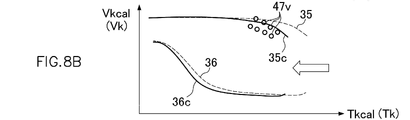
図8A~図8Dを併せて参照しつつ詳述すると、較正部41は、時間の経過に伴って変化する制御用の電圧値VHGconのリーン側尖頭値47vとグラフ35(リーン側閾値LREF)に対応するルックアップテーブルとを対比した際に、例えば、リーン側尖頭値47vがリーン領域にある場合には第1較正倍率値C1を増加してデータマップ及びルックアップテーブルを図8Aにおいて右側方向に向けて拡大し、リーン側尖頭値47vがストイキ領域にある場合には第1較正倍率値C1を減少してデータマップ及びルックアップテーブルを図8Bにおいて左側方向に向けて縮小する。
すなわち、較正部41は、上記増加又は減少した第1較正倍率値C1をデータマップ及びルックアップテーブルの第1目盛値G1に乗じることにより、所謂アフィン変換の要領でデータマップ及びルックアップテーブルを実質的に拡大又は縮小することで較正をする。なお、第1目盛値G1の拡縮原点には、0ケルビン(マイナス273.15degC;絶対零度)を採用することができる。このとき、記憶部34に記憶されている複数の第1目盛値G1の較正前の値をTk(摂氏温度)とした場合、較正後の制御用第1目盛値Tkcalは、次式(6a)により求められる。
Tkcal=(Tk+273.15)×C1-273.15 (6a)
Tkcal=(Tk+273.15)×C1-273.15 (6a)
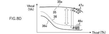
また、較正部41は、時間の経過に伴って変化する制御用の電圧値VHGconのリッチ側尖頭値46vとグラフ36(リッチ側閾値RREF)に対応するルックアップテーブルとを対比した際に、例えば、リッチ側尖頭値46vがリッチ領域にある場合には第2較正倍率値C2を増加してデータマップ及びルックアップテーブルを図8Dにおいて下方向に向けて拡大し、リッチ側尖頭値46vがストイキ領域にある場合には第2較正倍率値C2を減少してデータマップ及びルックアップテーブルを図8Cにおいて上方向に向けて縮小する。
すなわち、較正部41は、上記増加又は減少した第2較正倍率値C2をデータマップ及びルックアップテーブルの第2目盛値G2に乗じることにより、所謂アフィン変換の要領でデータマップ及びルックアップテーブルを実質的に拡大又は縮小することで較正する。なお、第2目盛値G2の拡縮原点には、上述の制御用の温度Tconが所定値以下の場合のグラフ35(リーン側閾値LREF)の値を採用することができる。
このとき、上記制御用の温度Tconが所定値以下の場合のグラフ35の値をLREFanchor、記憶部34に記憶されている複数の第2目盛値G2の較正前の値をVkとした場合、較正後の制御用第2目盛値Vkcalは、次式(7)により求められる。
Vkcal=(Vk-LREFanchor)×C2+LREFanchor (7)
Vkcal=(Vk-LREFanchor)×C2+LREFanchor (7)
なお、本実施の形態においては、上記第1較正倍率値C1及び第2較正倍率値C2の増加又は減少を行う場合に、所定の漸増率及び漸減率を介在させて第1較正倍率値C1又は第2較正倍率値C2を漸増又は漸減させて徐々に較正完了状態へと移行させる移行処理を含むように較正部41を構成することができる。
一方、酸素センサ12のストイキ振幅(ストイキメトリックでの振幅(波高))は、センサ素子12aの実際の温度に応じて変化し、振れ幅が変わる。例えば、酸素センサ12が、新品時に可及的に正確に実測した温度値が600degCである際、ストイキ振幅が4voltとなる特性を有するとして、その長期使用過程においてセンサヒータ12bに熱劣化(酸化)が生じてセンサヒータ12bの抵抗値が高まってくると、そのセンサヒータ12bの抵抗値から読み取って求められるセンサヒータ12bの温度及びセンサ素子12aの温度Tは、見かけ上、誤差を含んで実際の温度とは相違する値を示すことになる。
例えば、ヒータ温度読取部23aがセンサヒータ12bの抵抗値に基づいて読み取るセンサヒータ12bの温度Tが実測値600+50degCを示すようなセンサヒータ12bの熱劣化を有した酸素センサ12を、特性点検部40を介して観測すると、酸素センサ12のストイキ振幅特性は、あくまでもセンサ素子12aの実際の温度に沿って変化するので、見かけ上のセンサヒータ12bの温度及びセンサ素子12aの温度値Tが650degCのときにストイキ振幅は4voltとして観測されることになる。すなわち、この場合、見かけ上のセンサヒータ12bの温度及びセンサ素子12aの温度Tとストイキ振幅との対応関係は、センサヒータ12bが熱劣化していない新品時と比べて+50degCほどずれているように観測される。
而して、上記したようなデータマップのデフォルトでの対応関係からのずれを点検することにより、センサヒータ12bの抵抗値から読み取って求められるセンサヒータ12bの温度Tがセンサ素子12aの実際の温度値に対してどの程度の温度誤差を有するものであるかを精度良く把握することができる。また、この温度誤差が大きい場合は、センサヒータ12bが劣化したものと判断することができる。
そこで、本実施形態では、このセンサヒータ12bの劣化の有無を判定するために、複数の空気過剰率値を、センサヒータ12bの温度Tについての複数の第1目盛値G1及び電圧値VHGについての複数の第2目盛値G2との対応関係を付けて示す上述のデータマップ、並びに電圧値VHGがリッチ領域、ストイキ領域又はリーン領域の何れの空燃比領域に該当するかを判別するためのリッチ側閾値及びリーン側閾値を第1目盛値G1との対応関係を付けて示す上述のルックアップテーブルが利用される。
また、内燃機関の作動時に前記波高値を読み取りつつ、読み取った波高値の尖頭が前記空燃比領域の何れに該当するかを点検する上述の特性点検部40と、この点検の結果に基づいて、第1目盛値G1を補正して上記の対応関係を較正するための温度較正係数K(第1較正倍率値C1)を導出するために、上述の較正部41が利用される。
そして、温度較正係数Kの初期値と最新値との差の絶対値が、予め定めた劣化判定値よりも大きい場合には、センサヒータ12bが劣化していると判定する劣化判定部48がECU15に設けられる。
劣化判定部48は、温度較正係数Kの初期値を、較正部41による初期段階での較正時又は後述するOBD診断機によるリセットコマンドの発行時に取得し、その後、較正部41が温度較正係数Kの最新値を取得する毎に、初期値と最新値との差の絶対値を所定の劣化判定値と比較し、絶対値が劣化判定値を超えている場合、センサヒータ12bが劣化していると判定する。
すなわち、図5を用いて説明すれば、第1目盛値G1に関する温度較正係数Kについて、標準的なセンサヒータ12bの抵抗値(中央値)に対応して設定されているECU15のデフォルトの温度較正係数K値(ここでは第1目盛値G1をデフォルトから変化させない値であり、たとえばK=1.000倍とする)を図5においてラインAで示す一方、ECU15に接続された現実のセンサヒータ12bの抵抗値に対応する温度較正係数Kがその製造公差(特性ばらつき)等によって前記ラインAからずれているラインBで示されるものとすれば、劣化判定部48で取得される上記温度補正係数Kの初期値は、較正部41において上記ラインBに適合された温度較正係数Kの最新値を得て、該最新値を捕捉することにより設定される。この際、劣化判定部48は、後述する温度較正係数Kの初期値が設定されたか否かを例えばビット(1桁の2進数)で示す状態フラグFを温度較正係数Kの初期値が設定されたことを示す「1」に設定し、これにより、以降の温度較正係数Kの初期値の変更を禁止する。このように状態フラグFを「1」に設定した後も、センサヒータ12bの劣化等に因る抵抗値乃至温度値の経時変化にともなって温度較正係数Kの最新値は較正部41で更新されていくため、該更新が累積された温度補正係数Kの最新値は、例えば図5においてラインCやラインDで示されるような温度較正係数Kの初期値(ラインB)から乖離した値を示すようになる。而して劣化判定部48は、ラインBに示す第1目盛値G1に係る上記温度較正係数Kの初期値と、ラインCまたはDに示す温度較正係数Kの最新値との差が上記の劣化判定値を超えて離れた場合に、センサヒータ12bが劣化していると判定することができる。
例えば、劣化判定値が0.3、上記ラインBに係る温度較正係数Kの初期値が1.02、上記ラインCに係る温度較正係数Kの最新値が0.935であるとすれば、温度較正係数Kの初期値と最新値の差は0.085であり、この場合、劣化判定閾値0.3よりも小さいので、劣化していないと判定される。また、例えば、劣化判定値が0.3、上記ラインBに係る温度較正係数Kの初期値が1.03、上記ラインDに係る温度較正係数Kの最新値が1.35であるとすれば、温度較正係数Kの初期値と最新値の差は0.32であり、この場合、劣化判定閾値0.3よりも大きいのでセンサヒータ12bが劣化しているものと判定される。
ここで、劣化判定部48は、上記温度較正係数Kの初期値を適切に設定するために、上記状態フラグFを記憶するフラグ記憶部49を備える。フラグ記憶部49は、例えば、書き換え可能かつ記憶部への電源供給なしに記憶を保持することが可能な不揮発性メモリで形成される。フラグ記憶部49に記憶された状態フラグFが温度較正係数Kの初期値が未設定であることを示す「0(ゼロ)」の場合には、温度較正係数Kの初期値を温度較正係数Kの最新値と同一の値に設定し、状態フラグFが温度較正係数Kの初期値が設定されたことを示す「1」である場合には、温度較正係数Kの初期値の変更を禁止する。
これにより、劣化判定部48は、状態フラグFが温度較正係数Kの初期値が未設定であることを示す「0(ゼロ)」の場合には、温度較正係数Kの初期値と温度較正係数Kの最新値とが同じ値(差がゼロ)に設定されるため、温度較正係数Kの初期値を設定することができる。すなわち、温度較正係数Kについての所謂イニシャライザとしての機能を果たし、較正部41において較正された温度較正係数Kの最新値から温度較正係数Kの初期値が適正に設定される。
また、劣化判定部48は、温度較正係数Kの初期値が特性点検部40による点検の結果に基づいて適正に取得できたと判定した場合に、状態フラグFを、温度較正係数Kの初期値が設定されたことを示す値に設定する。
較正部41における較正は、瞬時の観測に基づくいわゆるワンショット学習ではなく、上述のように、徐々に導出される温度較正係数Kの増減を繰り返すことによって積分的に行われ、そうして導出される温度較正係数Kの最新値が飽和状態(サチュレート状態)に至って適正に取得できた(較正が完了した)と判定されるときに、劣化判定部48は状態フラグFをオン状態である「1」へと設定して、それ以降の温度較正係数Kの初期値の変更を禁止する。これにより、劣化判定部48が導出する温度較正係数Kの初期値は、再現性に優れた値のものとされる。
なお、上記温度較正係数Kの最新値、温度較正係数Kの初期値、及び状態フラグFは、外部の端末装置からの指令により所望の値に書き換え可能であってもよい。この場合、温度較正係数K及び状態フラグFは、外部端末装置としてのOBD診断機を介した操作で書き換えされることが好ましい。
たとえば、使用過程にある自動車のメンテナンス時に酸素センサ12を劣化品から新品に交換した場合は、OBD診断機による操作でECU15の学習値リセットコマンドの発動を行い、温度較正係数Kの最新値や初期値、及び状態フラグFなどの各パラメータを初期化することによって劣化判定部48による上記センサヒータ12bが劣化しているとの判定を解除する必要がある。これを行う操作機能を提供するために、ECU15は外部の端末装置と連携することができる。
ただしこの場合、センサ素子12aからの電圧値VHGの波高(振れ幅)は、センサ素子12aの実際の温度(真実値)に応じて変化するので、ECU15において、電圧値VHGの波高を読み取り、かつ、読み取った波高とセンサヒータ12bの抵抗値から読み取って求められるセンサ素子12aの温度Tとの対応関係が上記のデータマップと適合するか否かを特性点検部40により点検する際には、センサヒータ12bの温度を適温に制御する必要がある。すなわち、センサヒータ12bの温度が冷えすぎていても熱すぎていても適切な点検ができない。
そこで、本実施形態では、さらに、ECU15に、温度較正係数Kの逆数をセンサ素子12aの温度Tに乗じることにより、ヒータ発熱制御部22を制御するための温度Tcを求めるヒータ制御用温度導出部50を設け、ヒータ発熱制御部22により、温度Tcが目標温度Ttrgとなるようにセンサヒータ12bを発熱させる。
ヒータ制御用温度導出部50は、温度較正係数Kの最新値をKn、センサ素子12aの温度TをTnとすれば、次式によりセンサヒータ12bを制御するための温度Tcを求める。
Tc=Tn×(#1/Kn)
Tc=Tn×(#1/Kn)
ヒータ発熱制御部22は、この温度Tcと、目標温度Ttrgとの差分に応じてパルス幅変調した電圧を印加してセンサヒータ12bを発熱させる。
これにより、特性点検部40による点検が適切に行われ、ひいてはセンサヒータ12bの劣化有無の判定が適切に行われる。なお、この場合、目標温度値Ttrgは一定値に限らず、較正部41に連動させる形で振動的に動かすように設定してもよい。すなわち、温度条件を変えながら多点的に学習して温度校正係数Kを導出することもできる。
以上のように、本実施形態によれば、温度較正係数Kの初期値と、較正部41で求める温度較正係数Kの最新値との差の絶対値が予め定めた劣化判定値よりも大きい場合にはセンサヒータ12bが劣化していると判定する劣化判定部48を設けたので、センサヒータ12bの抵抗値から読み取るセンサヒータ12bの温度Tの較正や劣化の判定を行うに際して従来必要であったセンサヒータ12bの実際の温度を測定するための追加の温度センサを不要とすることができる。
また、内燃機関が作動している間に較正部41に連動させる形でセンサヒータ12bの劣化有無を判定できるので、従来の劣化有無を判定できるタイミングが来るまで長時間待たされるといった不都合を回避することができる。したがって、低コストでかつ動作制約の少ないセンサヒータ12bの劣化有無を判定できる内燃機関の制御装置を提供することができる。
また、劣化判定部48は、状態フラグFが温度較正係数Kの初期値が未設定であることを示す場合には、温度較正係数Kの初期値を最新値と同一の値に設定し、状態フラグFが温度較正係数Kの初期値が設定されたことを示す場合には、以降の温度較正係数Kの初期値の変更を禁止したので、較正部41で取得された温度較正係数Kの最新値によって温度較正係数Kの初期値を設定することができる。
また、劣化判定部48は、温度較正係数Kの初期値が適正に取得できたと判定した場合に、不揮発性メモリであるフラグ記憶部49の状態フラグFを、「1」(オン状態)に設定するので、温度較正係数Kの最新値が飽和状態へ至って適正にヒータ部の状態を捕捉できたと判定される以降に、状態フラグFをオン状態へと継続的に保持することができる。また、適正に取得された温度較正係数Kの初期値を再現性に優れた値に維持することができる。
また、劣化判定部48は、外部の端末装置からの指令により、前記温度較正係数Kの最新値、前記温度較正係数Kの初期値、及び前記状態フラグFを所望の値に書き換え可能としたので、使用過程にある自動車のメンテナンス時に酸素センサ12を劣化品から新品に交換した場合に、外部端末装置としてのOBD診断機を介した操作で使用過程にあるセンサヒータ12bが劣化しているとの判定等を解除することができる。
また、ヒータ制御用温度導出部50が求める温度Tcと目標温度Ttrgとの差分に応じてヒータ発熱制御部22によりセンサヒータ12bを発熱させるので、センサヒータ12bの温度を適温に制御し、特性点検部40による点検を適切に行い、ひいてはセンサヒータ12bの劣化有無の判定を適切に行うことができる。
以上、本発明の実施の形態について説明したが、本発明は上記実施の形態に限定されるものではなく、特許請求の範囲に記載された本発明を逸脱することなく種々の設計変更を行うことが可能である。
例えば、上述の実施の形態では、第1較正倍率値C1をデータマップ及びルックアップテーブルの複数の第1目盛値G1にそれぞれ乗じることにより、所謂アフィン変換の要領でデータマップ及びルックアップテーブルを実質的に拡大又は縮小することで較正するもの(式(6a))であったが、本発明はこれに限定されない。例えば、データマップ及びルックアップテーブルを走査する制御用の温度に第1較正倍率値C1を乗じる構成であってもデータマップ及びルックアップテーブルを実質的に拡大又は縮小することが可能であり、このとき、記憶部34に記憶されている複数の第1目盛値G1の較正前の値をTk(摂氏温度)、較正後の制御用第1目盛値をTkcalとした場合に、データマップ及びルックアップテーブルを走査するための走査制御用の温度値Tcon(摂氏温度)は、次式(6b)により求めることができる。
Tkcal=Tk
Tcon=(T+TD+273.15)×(1/C1)-273.15
(6b)
Tkcal=Tk
Tcon=(T+TD+273.15)×(1/C1)-273.15
(6b)
上述の式(6a)あるいは式(6b)いずれを用いる構成であっても、実際に計測した電圧値(検出値)VHGconの波高値がリッチ側及びリーン側閾値に合致する(波高の尖頭が閾値に重なる)ように較正して正確な空気過剰率を算出し、適切な空燃比フィードバック制御を行うことができる。また、特性点検部40による点検を適切に行いつつセンサヒータ12bの劣化有無の判定を適切に行うことができる。
また、上述の実施の形態では、温度Tconを設定するための基準値Trefを、冷却水温センサ17により得られるエンジン温度に吸気温センサ8により得られる吸気温度を加えて2で除する{Tref=(エンジン温度+吸気温度)÷2}ことにより設定しているが、これに限定されることなく、例えば、冷却水温センサ17により得られるエンジン温度又は吸気温センサ8により得られる吸気温度のいずれか一方のみから温度Tconを設定するための基準値Trefを算出するようにしてもよい。
1:機関本体、2:吸気管、3:スロットル弁、4:エアクリーナ、5:スロットルセンサ、6:燃料噴射弁、7:吸気圧センサ、8:吸気温センサ、9:ピストン、10:排気管、11:触媒、12:酸素センサ、12a:センサ素子(検出部)、12b:センサヒータ、13:点火プラグ、14:点火装置、15:ECU(電子制御ユニット)、17:冷却水温センサ、18:クランク軸、19:クランク角度センサ、19a:ロータ、19b:ピックアップ、20:大気圧センサ、22:ヒータ発熱制御部、23:温度算出部、23a:ヒータ温度読取部、23b:検出部温度推定部、24:電圧算出部、25:過剰率算出部、26:代替値演算部、27:回転速度演算部、28:目標値演算部、29:基本噴射量演算部、30:フィードバック係数演算部、31:噴射量演算部、32:トルク演算部、33:限界閾値設定部、34:記憶部、35~38、35b、36b、35c、36c、35d、36d、35e、36e:グラフ、40:特性点検部、41:較正部、42:温度差確認部、43:電圧差確認部、44:電圧波形、45:空燃比波形、46:リッチ側尖頭、47:リーン側尖頭、46v、47v:尖頭値、48:劣化判定部、49:フラグ記憶部、50:ヒータ制御用温度導出部。
Claims (5)
- 排気脈動を有する内燃機関の排気に接するように設けられ、前記排気のストイキメトリック近傍の酸素濃度において検出部の抵抗値がステップ状に変化する検出部と、前記検出部に隣接するヒータ部とを有し、前記検出部の抵抗値から求める検出値が前記検出部の温度と前記排気脈動とに応じた波高値を有するパルス波状を呈する高温排気ガス内酸素センサと、
前記ヒータ部の抵抗値に基づいて前記ヒータ部の温度を求めるヒータ温度読取部と、
前記ヒータ部の温度に基づいて前記検出部の温度を求める検出部温度推定部と、
複数の空気過剰率値を、前記検出部の温度についての複数の第1目盛値及び前記検出値についての複数の第2目盛値との対応関係を付けて示すデータマップ、並びに前記検出値がリッチ領域、ストイキ領域又はリーン領域の何れの空燃比領域に該当するかを判別するためのリッチ側閾値及びリーン側閾値を前記第1目盛値との対応関係を付けて示すルックアップテーブルを記憶する記憶部とを備える内燃機関の制御装置であって、
前記内燃機関の作動時に前記波高値を読み取りつつ、読み取った前記波高値の尖頭が前記空燃比領域の何れに該当するかを点検する特性点検部と、
前記点検の結果に基づいて、前記第1目盛値を補正して前記対応関係を較正するための温度較正係数を導出する較正部とを備え、
前記温度較正係数の初期値と最新値との差の絶対値が予め定めた劣化判定値よりも大きい場合には、前記ヒータ部が劣化していると判定する劣化判定部を有することを特徴とする内燃機関の制御装置。 - 前記劣化判定部は、前記温度較正係数の初期値が設定されたか否かを示す状態フラグを記憶するフラグ記憶部を備え、
前記状態フラグが前記温度較正係数の初期値が未設定であることを示す場合には、前記温度較正係数の初期値を前記温度較正係数の最新値と同一の値に設定し、
前記状態フラグが前記温度較正係数の初期値が設定されたことを示す場合には、前記温度較正係数の初期値の変更を禁止することを特徴とする請求項1に記載の内燃機関の制御装置。 - 前記劣化判定部は、前記温度較正係数の初期値が前記特性点検部による点検の結果に基づいて適正に取得できたと判定した場合に、前記フラグ記憶部の状態フラグを、前記温度較正係数の初期値が設定されたことを示す値に設定することを特徴とする請求項2に記載の内燃機関の制御装置。
- 外部の端末装置からの指令により、前記温度較正係数の最新値、前記温度較正係数の初期値、及び前記状態フラグを所望の値に書き換え可能であることを特徴とする請求項2に記載の内燃機関の制御装置。
- 前記温度較正係数の最新値をK、前記検出部の温度をTとして、次式によりヒータ制御用の温度Tcを求めるヒータ制御用温度導出部と、
Tc=T×(#1/K)
前記ヒータ制御用の温度Tcと、所定の目標温度Ttrgとの差分に応じてパルス幅変調した電圧を印加して前記ヒータ部を発熱させるヒータ発熱制御部とを備えることを特徴とする請求項1に記載の内燃機関の制御装置。
Priority Applications (1)
| Application Number | Priority Date | Filing Date | Title |
|---|---|---|---|
| DE112022001765.1T DE112022001765T5 (de) | 2021-03-25 | 2022-02-16 | Verbrennungsmotorsteuervorrichtung |
Applications Claiming Priority (2)
| Application Number | Priority Date | Filing Date | Title |
|---|---|---|---|
| JP2021052468A JP7591448B2 (ja) | 2021-03-25 | 2021-03-25 | 内燃機関の制御装置 |
| JP2021-052468 | 2021-03-25 |
Publications (1)
| Publication Number | Publication Date |
|---|---|
| WO2022201983A1 true WO2022201983A1 (ja) | 2022-09-29 |
Family
ID=83396892
Family Applications (1)
| Application Number | Title | Priority Date | Filing Date |
|---|---|---|---|
| PCT/JP2022/006157 Ceased WO2022201983A1 (ja) | 2021-03-25 | 2022-02-16 | 内燃機関の制御装置 |
Country Status (3)
| Country | Link |
|---|---|
| JP (1) | JP7591448B2 (ja) |
| DE (1) | DE112022001765T5 (ja) |
| WO (1) | WO2022201983A1 (ja) |
Citations (3)
| Publication number | Priority date | Publication date | Assignee | Title |
|---|---|---|---|---|
| WO2012165174A1 (ja) * | 2011-06-01 | 2012-12-06 | シャープ株式会社 | 抵抗加熱ヒータの劣化検出装置および方法 |
| JP6254633B2 (ja) * | 2016-03-31 | 2017-12-27 | 株式会社ケーヒン | 内燃機関制御装置 |
| JP2019094829A (ja) * | 2017-11-22 | 2019-06-20 | 株式会社ケーヒン | 酸素濃度検出器の劣化判定装置 |
Family Cites Families (1)
| Publication number | Priority date | Publication date | Assignee | Title |
|---|---|---|---|---|
| JP5206774B2 (ja) * | 2010-11-25 | 2013-06-12 | トヨタ自動車株式会社 | 触媒劣化の診断装置 |
-
2021
- 2021-03-25 JP JP2021052468A patent/JP7591448B2/ja active Active
-
2022
- 2022-02-16 WO PCT/JP2022/006157 patent/WO2022201983A1/ja not_active Ceased
- 2022-02-16 DE DE112022001765.1T patent/DE112022001765T5/de active Pending
Patent Citations (3)
| Publication number | Priority date | Publication date | Assignee | Title |
|---|---|---|---|---|
| WO2012165174A1 (ja) * | 2011-06-01 | 2012-12-06 | シャープ株式会社 | 抵抗加熱ヒータの劣化検出装置および方法 |
| JP6254633B2 (ja) * | 2016-03-31 | 2017-12-27 | 株式会社ケーヒン | 内燃機関制御装置 |
| JP2019094829A (ja) * | 2017-11-22 | 2019-06-20 | 株式会社ケーヒン | 酸素濃度検出器の劣化判定装置 |
Also Published As
| Publication number | Publication date |
|---|---|
| JP2022150053A (ja) | 2022-10-07 |
| DE112022001765T5 (de) | 2024-01-25 |
| JP7591448B2 (ja) | 2024-11-28 |
Similar Documents
| Publication | Publication Date | Title |
|---|---|---|
| JP5543134B2 (ja) | 内燃機関の燃料噴射器を較正する方法および制御装置、プログラムおよび記憶媒体 | |
| US8656898B2 (en) | Method for controlling a glow plug | |
| JP5032701B2 (ja) | 内燃機関の噴射システムの制御方法および制御装置 | |
| JP4705690B2 (ja) | 内燃機関に対する少なくとも1つの測定センサの出力信号の分解能を高めるための方法並びに所属の制御装置 | |
| US9982620B2 (en) | Method for the correction of a fuel quantity injected by means of a fuel injection device during operation of an internal combustion engine | |
| JP2004061506A (ja) | 空気管路内の空気流量を求める方法およびエアマスフローセンサユニット | |
| Guardiola et al. | Cylinder charge composition observation based on in-cylinder pressure measurement | |
| WO2016051755A1 (ja) | 内燃機関の制御装置 | |
| JP5381755B2 (ja) | 筒内圧センサの出力補正装置 | |
| US7606650B2 (en) | In-cylinder pressure detection device and method for internal combustion engine, and engine control unit | |
| WO2022172656A1 (ja) | 空燃比制御装置 | |
| US20100191443A1 (en) | Method for the determination of an injected fuel mass of a preinjection | |
| JP2021501849A (ja) | ドリフト補償のための電荷増幅器および測定システムならびにドリフト補償方法 | |
| JP7591448B2 (ja) | 内燃機関の制御装置 | |
| JP2007120392A (ja) | 内燃機関の空燃比制御装置 | |
| US20040128059A1 (en) | Method for determining the oil temperature in an internal combustion engine | |
| JP7437341B2 (ja) | 空燃比制御装置 | |
| US7295917B2 (en) | Method for determining a combustion chamber pressure | |
| JP7499146B2 (ja) | 空気過剰率算出装置 | |
| JP2008303860A (ja) | 燃料性状補正装置 | |
| KR102323408B1 (ko) | 엔진의 기통별 공연비 편차 보정 방법 | |
| WO2023181292A1 (ja) | 空燃比制御装置 | |
| JP4075312B2 (ja) | エンジンの燃焼制御方法とその装置 | |
| CN104838116B (zh) | 喷射到发动机尤其柴油发动机中的燃料量的确定方法 | |
| WO2024154241A1 (ja) | 内燃機関の制御装置 |
Legal Events
| Date | Code | Title | Description |
|---|---|---|---|
| 121 | Ep: the epo has been informed by wipo that ep was designated in this application |
Ref document number: 22774783 Country of ref document: EP Kind code of ref document: A1 |
|
| WWE | Wipo information: entry into national phase |
Ref document number: 202347070073 Country of ref document: IN |
|
| WWE | Wipo information: entry into national phase |
Ref document number: 112022001765 Country of ref document: DE |
|
| 122 | Ep: pct application non-entry in european phase |
Ref document number: 22774783 Country of ref document: EP Kind code of ref document: A1 |