WO2022201956A1 - 回転電機、回転電機用の電気端子、及び回転電機の製造方法 - Google Patents
回転電機、回転電機用の電気端子、及び回転電機の製造方法 Download PDFInfo
- Publication number
- WO2022201956A1 WO2022201956A1 PCT/JP2022/005572 JP2022005572W WO2022201956A1 WO 2022201956 A1 WO2022201956 A1 WO 2022201956A1 JP 2022005572 W JP2022005572 W JP 2022005572W WO 2022201956 A1 WO2022201956 A1 WO 2022201956A1
- Authority
- WO
- WIPO (PCT)
- Prior art keywords
- terminal
- coil
- wire harness
- electrical
- joint surface
- Prior art date
- Legal status (The legal status is an assumption and is not a legal conclusion. Google has not performed a legal analysis and makes no representation as to the accuracy of the status listed.)
- Ceased
Links
Images


Classifications
-
- H—ELECTRICITY
- H02—GENERATION; CONVERSION OR DISTRIBUTION OF ELECTRIC POWER
- H02K—DYNAMO-ELECTRIC MACHINES
- H02K15/00—Processes or apparatus specially adapted for manufacturing, assembling, maintaining or repairing of dynamo-electric machines
- H02K15/04—Processes or apparatus specially adapted for manufacturing, assembling, maintaining or repairing of dynamo-electric machines of windings prior to their mounting into the machines
-
- H—ELECTRICITY
- H02—GENERATION; CONVERSION OR DISTRIBUTION OF ELECTRIC POWER
- H02K—DYNAMO-ELECTRIC MACHINES
- H02K3/00—Details of windings
- H02K3/04—Windings characterised by the conductor shape, form or construction, e.g. with bar conductors
-
- H—ELECTRICITY
- H02—GENERATION; CONVERSION OR DISTRIBUTION OF ELECTRIC POWER
- H02K—DYNAMO-ELECTRIC MACHINES
- H02K3/00—Details of windings
- H02K3/32—Windings characterised by the shape, form or construction of the insulation
- H02K3/38—Windings characterised by the shape, form or construction of the insulation around winding heads, equalising connectors, or connections thereto
Definitions
- the description in this specification relates to a rotating electrical machine, an electrical terminal for the rotating electrical machine, and a method of manufacturing the rotating electrical machine, and the rotating electrical machine of the present disclosure is suitable for use as a generator or starter for a two-wheeled vehicle.
- Patent Document 1 discloses that a coil and a wire harness are used in this type of rotary electric machine, that the coil and the wire harness are electrically connected by an electrical terminal, and that the electrical terminal is covered with a metal coating. .
- the parts of the electrical terminals other than the joint surface with the coil are arranged in the housing portion of the stator in the assembled state of the rotating electrical machine, and the periphery thereof is filled with protective resin.
- the protective resin repeats expansion and contraction within the accommodating portion due to changes in the external temperature. Therefore, if the expansion and contraction of the protective resin continue for a long period of time, the possibility that the metal coating may crack or come off from the surface of the electrical terminal cannot be ignored. Once the metal coating is cracked or peeled off from the surface of the electrical terminal, foreign matter such as water may enter the gap between the metal coating and the surface of the electrical terminal. Therefore, there is a possibility that the electrical terminals will be corroded by corrosive substances such as water. If the corrosion of the electrical terminals progresses to the joint surface with the coil, it will cause performance deterioration and damage the reliability of the rotating electric machine.
- an object of the present disclosure is to reliably protect the joint surfaces of the electrical terminals and the coils before the electrical terminals are assembled to the stator of the rotating electrical machine without using antirust paper or the like. and Another object of the present disclosure is to make it difficult to corrode a joint surface with a coil in a state after the electrical terminal is assembled to the stator of the rotary electric machine.
- the first aspect of the present disclosure is a rotor that has a plurality of permanent magnets arranged in the circumferential direction and rotates with the shaft, a plurality of teeth and a plurality of coils arranged on the teeth, and the radially outer ends of the teeth are provided.
- the rotating electric machine includes a stator facing a magnet and a wire harness for energizing a coil.
- the coil is made of aluminum and the coil terminals are arranged on the stator, and the wire harness is made of copper and the wire harness terminals are arranged on the stator.
- An iron electrical terminal welded to the coil terminal and soldered to the wire harness terminal is placed in the accommodation portion of the stator, and a protective resin is filled in the accommodation portion while the electrical terminal is accommodated in the accommodation portion.
- the surface of the electrical terminal to be welded with the coil terminal and the surface of the electrical terminal to be soldered with the wire harness terminal are coated with a tin film before welding and soldering.
- a base material exposed portion having no film is formed on a portion of the electrical terminal other than the surface to be welded to the coil terminal and the surface to be soldered to the wire harness terminal.
- the protective resin is in direct contact with the substrate exposed portion when the electrical terminal is housed in the housing portion.
- a tin coating portion is formed on the surface of the electrical terminal to be welded to the coil terminal and the surface to be soldered to the wire harness terminal before welding and soldering. Therefore, important parts such as the weld joint surface and the soldering surface are protected by the tin coating. In the state before welding and soldering, even if it is left for a long time without applying rust-preventive oil or wrapping it in rust-preventive paper, the occurrence of rust etc. on important joint surfaces is suppressed. be done.
- the protective resin when the electrical terminal is housed in the housing portion, the protective resin is in direct contact with the exposed portion of the base material. There is no tin coating between the substrate and the protective resin except for the soldering surface. Therefore, no gaps are generated due to cracking or peeling of the tin coating, and there is no penetration of corrosive substances such as water caused by gaps caused by the cracking or peeling. As a result, corrosion of the weld joint surface with the coil terminal due to intrusion of corrosive substances such as water is prevented, and the reliability of the weld joint surface is improved.
- the welded joint surface of the electrical terminal with the coil terminal is configured so that there is a non-existent portion of the tin coating portion in the state after the welded joint.
- the tin coating protects the weld joint surface from rust before welding. Therefore, even if a part melts and flows out due to welding with an aluminum coil, it is sufficient that the rust preventive effect is maintained before welding.
- the third aspect of the present disclosure is that the surface of the electrical terminal to be soldered to the wire harness terminal is still made of tin after soldering.
- the tin film portion, which is formed on the soldering surface even after soldering, is in direct contact with the protective resin.
- the third aspect of the present disclosure is that the surface of the electrical terminal to be soldered to the wire harness terminal is still coated with tin after soldering. An effect of improving workability during soldering can also be obtained. In addition, the antirust effect after soldering can be maintained.
- the third aspect of the present disclosure is that the tin film portion, which is formed even after soldering on the soldering surface of the electrical terminal with the wire harness terminal, is in direct contact with the protective resin, so it can be used for a long time. It is undeniable that the tin coating may crack or peel off from the electrical terminal due to the passage of time. However, even if the tin film cracks or peels off and a gap is created, the base material and the parts other than the welding joint surface with the coil terminal and the soldering surface with the wire harness terminal of the electrical terminal will not be exposed.
- any cracks or peeling of the tin film may occur in areas other than the weld joint surface with the coil terminal and the soldering surface with the wire harness terminal. will not advance to Therefore, the weld joint surface to the coil terminal will not corrode due to the intrusion of corrosive substances such as water, and the reliability of the weld joint surface can be maintained.
- a fourth aspect of the present disclosure is that the coil terminals are arranged on one surface of the stator and the wire harness terminals are arranged on the other surface of the stator. Welding of coil terminals and soldering of wire harness terminals can be performed on the opposite side of the stator.
- a fifth aspect of the present disclosure is an electrical terminal used in a rotating electric machine.
- the surface of the electrical terminal to be welded with the coil terminal and the surface of the electrical terminal to be soldered with the wire harness terminal are made of tin before welding and soldering. is composed of the coating part, and the parts other than the welding joint surface with the coil terminal of the electrical terminal and the soldering surface with the wire harness terminal are coated with a tin coating in the state before welding and after soldering
- a substrate exposed portion is configured in which the portion is absent.
- a sixth aspect of the present disclosure is a rotor that has a plurality of permanent magnets arranged in the circumferential direction and rotates with the shaft, a plurality of teeth, and a plurality of coils arranged on the teeth, and the radially outer ends of the teeth are provided.
- a method of manufacturing a rotating electric machine including a stator facing a magnet and a wire harness for energizing a coil.
- the coil is made of aluminum and the coil terminals are arranged on one side surface of the stator, the wire harness is made of copper and the wire harness terminals are arranged on the other side surface of the stator, and the coil It is also a method of manufacturing a rotating electrical machine in which a terminal and a wire harness terminal are electrically connected with an iron electrical terminal.
- a sixth method for manufacturing a rotating electrical machine of the present disclosure comprises first forming a coating portion on a joint surface of an electrical terminal with a coil terminal and a joint surface with a wire harness terminal, and The electric terminal is partially plated with a tin film portion so that the portion other than the joint surface with the harness terminal constitutes a substrate exposed portion where the film portion does not exist.
- a fifth method for manufacturing a rotating electrical machine of the present disclosure includes, after partial plating, housing the electrical terminals in housings of the stator, welding the joint surfaces of the electrical terminals to the coil terminals, and applying protective resin to the housings. and soldering the contact surface of the electrical terminal with the wire harness terminal.
- a tin film portion is partially plated so as to form a film portion on the joint surface of the electrical terminal with the coil terminal and the joint surface with the wire harness terminal. Therefore, it is possible to reliably protect the joint surface with the coil terminal before welding and the joint surface with the wire harness terminal before soldering. Even after a long period of time from partial plating to welding or soldering, the joint surface can be protected from corrosion.
- the substrate exposed portion is configured such that the coating portion does not exist in the portion other than the joint surface of the electric terminal with the coil terminal and the joint surface with the wire harness terminal.
- the tin film portion is partially plated, and then the housing portion is filled with a protective resin. Therefore, the tin coating portion is not interposed between the protective resin and the substrate exposed portion. Therefore, cracking or peeling of the tin coating does not occur at the substrate exposed portion, and no gap is generated due to cracking or peeling. Thereby, the reliability of the rotating electric machine manufactured by the sixth manufacturing method of the present disclosure can be improved.
- the joint surface of the electrical terminal with the coil terminal or the joint surface with the wire harness terminal is plated, and then the joint surface with the coil terminal of the electrical terminal and the wire harness terminal are plated. Partial plating is performed by plating either one of the joint surfaces of the two.
- the contact surface of the electrical terminal with the coil terminal and the contact surface with the wire harness terminal are plated with a tin film, so the contact surface of the electrical terminal with the coil terminal and the wire harness terminal It is possible to form a substrate exposed portion in which the film portion is absent in a portion other than the joint surface with the substrate.
- the eighth aspect of the present disclosure is to first mask the portions of the electrical terminal other than the joint surface with the coil terminal and the joint surface with the wire harness terminal with tape, and then immerse the electrical terminal in a plating bath to remove the electrical terminal. Partial plating is performed by plating the film portion on the joint surface with the coil terminal and the joint surface with the wire harness terminal, and then peeling off the tape.
- the base material exposed part where the coating part is absent is accurately configured. can do.
- FIG. 1 is a perspective view of a state in which a rotating electric machine is combined with a crankshaft and an engine cover.
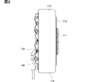
- FIG. 2 is a side view showing a rotating electric machine.
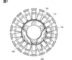
- FIG. 3 is a front view showing a rotating electric machine.
- FIG. 4 is a front view showing a stator material.
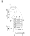
- FIG. 5 is a cross-sectional view schematically showing electrodes.
- FIG. 6 is a front view showing the stator before being sealed with protective resin.
- FIG. 7 is a front view showing the stator after being sealed with protective resin.
- FIG. 8 is a front view of an electrical terminal;
- FIG. 9 is a side view of an electrical terminal;
- FIG. 10 is a cross-sectional view showing a state in which the electrical terminals are arranged in the accommodation portion of the stator.
- FIG. 11 is a cross-sectional view taken along line XI--XI in FIG. 10.
- FIG. 12 is an explanatory diagram showing an example of the process of partial plating.
- FIG. 13 is an explanatory diagram showing another example of the partial plating process.
- 14A and 14B are explanatory views showing the steps of the partial plating shown in FIG. 13.
- FIG. 15A and 15B are explanatory diagrams showing the forming process of the electrical terminal.
- FIG. 16 is a cross-sectional view showing a state in which the rotating electric machine is attached to the engine.
- FIG. 17 is a front view showing another example of the covering portion of the electrical terminal.
- FIG. 18 is a front view showing an example in which a covering portion and a covering portion protective member are arranged on an electrical terminal.
- FIG. 19 is a cross-sectional view showing an example in which a covering portion and a covering portion protective member are arranged on an electrical terminal.
- 20 is a cross-sectional view taken along line XX-XX of FIG. 19.
- FIG. 21 is a cross-sectional view showing the behavior of the coating portion protective material.
- FIG. 22 is a cross-sectional view showing another behavior of the coating part protective material.
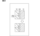
- FIG. 23 is a cross-sectional view showing still another behavior of the coating portion protective material.
- FIG. 1 is a perspective view of a state in which rotating electric machine 100 is combined with crankshaft 200 and engine cover 201 .
- FIG. 16 is a cross-sectional view showing a state in which the rotating electric machine is attached to the engine.
- Reference numeral 202 denotes a web that receives reciprocating motion of a piston (not shown) in a cylinder (not shown) via a connecting rod (not shown) to rotate the crankshaft 200 .
- Crankshaft 200 is made of an iron material with a diameter of about 20 mm and is rotatably supported by cylinder block 210 .
- the engine cover 201 shown in FIG. 1 covers the opening of the cylinder block 210 and is bolted to the cylinder block through bolt through holes 203 .
- the engine cover 201 is made of die-cast aluminum or aluminum alloy and has a thickness of about 4 millimeters. Since the engine cover 201 continues to the opening of the cylinder block, the internal environment is similar to that of the cylinder block. On the other hand, the engine cover 220 shown in FIG. Therefore, the internal environment is close to the outside air and is susceptible to splashing of water or the like.
- a rotor 110 of the rotary electric machine 100 is fixed to the crankshaft 200 with a base portion 111 (shown in FIGS. 2 and 16). Therefore, rotor 110 rotates integrally with crankshaft 200 .
- the rotor 110 is made of a ferrous material and includes a disk portion 112 extending radially outward from a base portion 111 and a cylindrical portion 113 formed radially outwardly of the disk portion 112 .
- twelve permanent magnets 114 are arranged side by side in the circumferential direction. The thickness of this permanent magnet 114 is about 4 to 5 millimeters. Note that the number of permanent magnets 114 is not limited to 12, and can be appropriately set to 20, 24, or the like according to the required performance.
- a stator 140 is arranged inside the rotor 110 .
- the stator 140 is formed by laminating a plurality of stator materials 1401 (shown in FIG. 4) made of magnetic steel plates. are integrally formed.
- FIG. 4 shows one of the stator blanks 1401 that make up the stator 140 .
- the number of teeth 142 is the same as the number of permanent magnets 114, and is 18 in the example of FIG. However, the number is changed according to the required performance, such as 12 or 24, as described above.
- the outer diameter of the stator 140 is about 90 to 130 mm, so the inner diameter of the rotor 110 is large enough to form a minute gap between the outer diameter of the stator 140 and the permanent magnets 114 .
- the base portion 141 is formed with three stator bolt through holes 143 for fixing the stator 140 to the engine cover 201 .
- a sensor case 160 is fixed to the base portion 141 .
- Reference numeral 144 in FIG. 4 denotes a sensor case bolt through hole for fixing the sensor case 160 to the base.
- the base portion 141 is formed with three housing holes 145 for housing electric terminals 130 to be described later.
- the teeth 142 are electrically insulated by insulators 146 (shown in FIGS. 5, 10, and 11) made of an insulating resin such as polyamide, and a coil 170 made of an aluminum wire having a diameter of about 2 mm is wound around the insulator 146.
- insulators 146 shown in FIGS. 5, 10, and 11
- a coil 170 made of an aluminum wire having a diameter of about 2 mm is wound around the insulator 146.
- aluminum includes pure aluminum and aluminum alloys.
- the aluminum wire is insulated and coated with a resin such as polyimide or polyesterimide.
- the sensor case 160 four Hall sensors are arranged between adjacent coils 170 so as not to contact the coils 170.
- the detection positions of the three Hall sensors correspond to the energization timings of the V phase, W phase, and U phase. Therefore, when rotating electric machine 100 is used as a motor as a starter, the voltage supply to coils 170 corresponding to the U-phase, V-phase, and W-phase is controlled. Also when the rotary electric machine 100 is used as a generator, it is used as a timing signal for controlling the output currents from the coils 170 corresponding to the U-phase, V-phase, and W-phase.
- the remaining Hall sensor detects a reference position for engine ignition control.
- the coils 170 correspond to U-phase, V-phase, and W-phase.
- reference numeral 171 denotes the coil 170 corresponding to the U phase
- reference numeral 172 denotes the coil 170 corresponding to the V phase
- reference numeral 173 denotes the coil 170 corresponding to the W phase.
- a U-phase coil 171, a V-phase coil 172, and a W-phase coil 173 are electrically connected by a bus bar 120 at a neutral point.
- Busbar 120 is made of a ferrous material.
- iron includes iron-based iron alloys in addition to pure iron. Iron alloys include relatively low carbon steel sheets such as cold rolled steel.
- Bus bar 120 is insert-molded into insulator 146 . However, the bus bar 120 may be press-fitted into the insulator 146 in a later step.
- the U-phase coil 171, the V-phase coil 172, and the W-phase coil 173 are electrically connected to the electrical terminal 130 at their respective coil terminals.
- the electrical terminals 130 also include three terminals 131 for the U phase, 132 for the V phase, and 133 for the W phase.
- the U-phase corresponding terminal 131, the V-phase corresponding terminal 132, and the W-phase corresponding terminal 133 are all made of the same material and have the same shape.
- the material is iron like the busbar 120 .
- the shape is a plate with a length of about 30 mm, a width of about 5 mm, and a thickness of about 1 mm.
- the insulator 146 forms a housing portion 147 in the housing hole 145 of the base portion 141 . Accordingly, the accommodation portion 147 is provided in the stator 140 .
- the electric terminal 130 is housed in this housing portion 147 .
- Two locking shoulders 134 are formed on both side surfaces of the electrical terminal 130 to prevent the electrical terminal 130 from moving when it is housed in the housing portion 147 .
- the locking shoulder portion 134 is provided on one end side in the length direction of the electrical terminal 130, and in this example, is formed closer to the coil joint surface 140a, which will be described later.
- a rib 136 is formed to bulge out from the middle portion of the electrical terminal 130 .
- the coil terminals of the coil 170 electrically connected to the busbar 120 and the coil terminals of the coil 170 electrically connected to the electrical terminal 130 are both arranged on one surface 140a of the stator 140 .
- This one-side surface 140a is a surface on which the engine cover 201 is not arranged.
- the coil terminals correspond to the winding start and winding end of the U-phase coil 171, the V-phase coil 172, and the W-phase coil 173, respectively.
- reference numerals 171, 172, and 173 in FIG. 5 indicate coil terminal portions of the U-phase coil 171, the V-phase coil 172, and the W-phase coil 173, respectively.
- the electric terminal 130 penetrates the housing portion 147 and protrudes to the other side surface 140b of the stator 140.
- the U-phase corresponding terminal 131, the V-phase corresponding terminal 132, and the W-phase corresponding terminal 133 are electrically connected to the wire harness 180 on the other surface 140b.
- the wire harness 180 is a coated conductor in which a wire rod 181 made of a bundle of many fine copper wires is covered with a resin coating portion 182 .
- the wire rods 181 of the wire harness 180 correspond to the U-phase terminal 131, the V-phase terminal 132, and the W-phase terminal 133, respectively. 187.
- copper includes not only pure copper but also copper alloys containing copper as the main component.
- the coil-side joint surface 137 of the electrical terminal 130 is formed with a convex coil connection portion 1371 with which the coil terminal of the coil 170 abuts.
- a wire harness connection groove 1391 into which the end of the wire harness 180 is fitted is formed in the wire harness side joint surface 139 on the opposite side.
- the coil-side joint surface 137 is welded to the coil terminal of the coil 170, so the coil-side joint surface 137 serves as a weld joint surface.
- the wire harness side joint surface 139 is soldered to the wire harness terminal of the wire harness 180, the wire harness side joint surface 139 serves as a soldering surface.
- a coating portion 1372 made of tin is formed on the coil-side joint surface 137 of the electrical terminal 130 before the coil 170 is connected.
- a tin coating portion 1392 is also formed on the wire harness side joint surface 139 on the opposite side before the wire harness 180 is connected.
- tin includes not only pure tin but also tin-based tin alloys.
- a coating portion 1372 is formed on the coil-side joint surface 137 of the electric terminal 130, and a coating portion 1392 is formed on the wire harness-side joint surface 139.
- the intermediate portion of the electric terminal 130 is a substrate exposed portion 138 where no coating portion exists. It has become.
- the iron material is exposed as it is, but when the material of the electrical terminal 130 is surface-treated, the surface of the material that has been surface-treated is exposed.
- the bus bar 120 is also plated with a tin film. In the bus bar 120, not only the surface to be welded with the coil terminal but also the entire surface is plated with a film.
- a first potting portion 148 is formed on one side surface 140 a of the stator 140 so as to surround the connecting portion between the bus bar 120 and the coil 170 .
- a protective resin 190 made of epoxy resin is potted in the first potting portion 148 to seal the connecting portion between the bus bar 120 and the coil 170 . Therefore, the connecting portions between the bus bar 120 and the coil terminals of the coil 170 are not exposed to the outside air.
- the coil terminals are the winding start and winding end points of the coil 170, so the coil terminals welded to the bus bar 120 are also at the positions indicated by reference numerals 171, 172 and 173 in FIG.
- a second potting portion 149 is also formed on one side surface 140 a of the stator 140 so as to surround the connecting portion between the electrical terminal 130 and the coil 170 .
- a protective resin 190 made of epoxy resin is also potted in the second potting portion 149 to seal the connecting portion between the electrical terminal 130 and the coil 170 . Therefore, the connecting portion between the electrical terminal 130 and the coil 170 is not exposed to the outside air by the second potting portion 149 .
- the coil 170 is pulled out from the second potting portion 149, and the coil 170 is covered with insulation at the pulled-out portion.
- FIG. 7 shows a state in which the first potting portion 148 and the second potting portion 149 are filled with the protective resin 190 .
- protective resin 190 flows from second potting portion 149 to accommodating portion 147 .
- the protective resin 190 is arranged over the entire length of the stator 140 from one surface 140a to the other surface 140b.
- the accommodating portion 147 is provided in the base portion 141, it cannot be enlarged and can be said to be a narrow through hole. Therefore, the distance from the electrical terminal 130 is at most several millimeters. Therefore, the thickness of the protective resin 190 that fills this narrow space is also as thin as several millimeters. The thickness of the protective resin 190 is, as shown in FIG.
- the accommodation portion 147 has a cross shape, and the locking shoulder portion 134 of the electrical terminal 130 is engaged with the accommodation portion 147 . Further, the rib 136 of the electrical terminal 130 is also engaged with the receiving portion 147 . Therefore, the position of the electrical terminal 130 is determined by the locking shoulder portion 134 and the rib 136 within the accommodating portion 147, and the position is fixed by the protective resin 190 in that state.
- a stator material 1401 is stamped from a magnetic steel plate material, and a plurality of stator materials 1401 are joined using connecting portions 1402 (shown in FIG. 4) formed on a base portion 141 and teeth portions 142 . This joining is performed by press molding.
- a preformed insulator 146 is attached to the outer periphery of the stator material 1401 .
- the stator material 1401 is insulated.
- the bus bar 120 is also insert-molded.
- the bus bar 120 can also be press-fitted after the insulator 146 is assembled.
- a housing portion 147 is formed by the insulator 146 in the housing hole 145 . More specifically, the insulator 146 in which the accommodation portion 147 is formed in advance is attached to the outer periphery of the stator material 1401 to form the accommodation portion 147 .
- a coil 170 is wound by winding an aluminum wire with an insulation coating on the insulator 146 .
- the electric terminal 130 is formed in a separate process from the molding of the stator material 1401, the molding of the insulator 146, and the winding of the coil 170. Formation of electrical terminals 130 begins with partial plating, as shown in FIG. First, a rewinding step 1310 of rewinding the iron material plate 1301 from the hoop material 1302 around which the belt-like iron material plate 1301 is wound is performed.
- a first partial plating process PLT1312 is performed.
- the first partial plating process PLT1312 only the lower portion of the iron material plate 1301 is immersed in a molten tin plating bath to form a tin coating 1304 on the lower portion of the iron material plate 1301.
- the dashed line LQS1318 indicates the molten tin surface.
- the second partial plating process PLT1313 is performed.
- this second partial plating process PLT1313 only the lower part of the iron material plate 1301 is immersed in molten tin using the same plating tank as used in the first partial plating process PLT1312.
- the molten tin surface 1318 indicated by the dashed line LQS is also the same as the first partial plating step PLT1312.
- the iron material plate 1301 is cooled in the cooling process COL1314, and then rolled up into a cylindrical shape in the winding process 1315 to form the final hoop material 1306.
- the film 1304 applied in the first partial plating step 1312 exists on the upper portion of the final hoop material 1306, and the film 1305 applied in the second partial plating step PLT1313 exists on the lower portion. .
- the iron material plate 1301 was immersed in the plating tank twice, the first partial plating process PLT1312 and the second partial plating process PLT1313. masking may be performed.
- Rewinding the hoop material 1302 obtained by winding the iron material plate 1301 into a roll into a flat plate in the unwinding step 1310 and then cleaning the surface of the iron material plate 1301 in the cleaning step CLN 1311 are the steps of the partial plating described above. are the same.
- the masking tape 1321 is taken out from the tape roller 1320, and the tape 1321 is adhered to the central portion of the steel material plate 1301.
- the iron material plate 1301 masked with the tape 1321 is immersed in a molten tin plating bath.
- the molten tin surface 1319, indicated by the dashed line LQS, is above the partial plating and the iron blank 1301 is deeply immersed in the plating bath.
- the iron material plate 1301 and the tape 1321 are cooled, and the tape 1321 is rewound by the tape releaser 1322.
- the iron material plate 1301 is wound to form a final roll hoop material 1306 .
- the central portion masked by the tape 1321 is not coated, and coatings 1304 and 1305 are formed on the upper and lower portions, respectively.
- the substrate exposed portion 138 may be formed by coating the entire surface of the iron material plate 1301 with a tin coating and melting the tin coating in the intermediate portion.
- the substrate exposed portion 138 may be formed by mechanically removing the tin film in the intermediate portion.
- FIG. 15 shows the process of forming the electrical terminal 130 from the final hoop material 1306 on which the coating 1304 and coating 1305 are formed.
- the flat iron material plate 1301 unwound in the unwinding step 1310 is press-formed in the forming step 1317 to form the electrical terminal 130 .
- the coil connection portion 1371, the wire harness connection groove 1391, the locking shoulder portion 134, and the rib 136 are formed.
- Forming step 1317 also causes coating 1304 and coating 1305 to form coating portion 1372 and coating portion 1392 of electrical terminal 130 . Further, an intermediate portion other than the coated portion 1372 and the coated portion 1392 becomes the substrate exposed portion 138 .
- the molding step 1317 also forms a frame 1309 that connects the plurality of electrical terminals 130 .
- a separation step 1331 is performed to separate the electrical terminals 130 from the frame 1309 .
- the electrical terminal 130 is molded in this manner, and then the next manufacturing process is performed.
- the coil 170 is placed in the accommodating portion 147 of the stator 140 wound thereon.
- the coating portion 1372 and the coating portion 1392 of the electrical terminal 130 protrude from opposite surfaces (one surface 140a and the other surface 140b).
- the intermediate substrate exposed portion 138 is arranged in the accommodation portion 147 .
- the insulating coating of the coil terminal of coil 170 is peeled off and welded to bus bar 120 .
- Welding is performed by sandwiching the coil terminal from which the insulation coating of the coil 170 has been removed and the bus bar 120 between electrodes, and energizing between the electrodes. Welding at this time is performed at three locations, the coil 172 corresponding to the V phase and the coil 173 corresponding to the W phase.
- the coil terminal of the coil 170 and the electrical terminal 130 are also welded on the one side surface 140a of the stator 140 .
- the coil terminal from which the insulation coating of the coil 170 has been stripped is brought into contact with the coil connection portion 1371 of the electrical terminal 130, and in this state, the coil terminal and the electrical terminal 130 are sandwiched between the electrodes. It is done by energizing between Welding at this time is also performed at three points between the V-phase corresponding coil 172 and the W-phase corresponding coil 173 and the U-phase corresponding terminal 131 , the V-phase corresponding terminal 132 and the W-phase corresponding terminal 133 .
- the welding between the terminals of the coil 170 and the bus bar 120 and the welding between the terminals of the coil 170 and the electrical terminals 130 may be performed first or may be performed at the same time. Since both are performed on one side surface 140a of the stator 140, welding can be performed in the same welding environment.
- the coating portion 1372 covering the coil-side joint surface 137 melts and flows out. Therefore, the electrical terminal 130 made of iron and the coil 170 made of aluminum are directly welded. This directly welded portion becomes a non-coated portion.
- the main function of the tin coating portion 1372 is to protect the coil side joint surface 137 before welding. This is because the coil-side joint surface 137 is required to be clean in order to perform good welding with the terminals of the coil 170 . According to the present disclosure, since the coil-side joint surface 137 is covered with the coating portion 1372 until just before welding, the coil-side joint surface 137 can be effectively prevented from being rusted or the like.
- the first potting part 148 and the second potting part 149 are assembled to the insulator 146 . Then, the protective resin 190 is filled in the first potting portion 148 and the second potting portion 149 . Since the first potting portion 148 is a closed space, the protective resin 190 stays within the first potting portion 148 . On the other hand, since the accommodating portion 147 is open in the second potting portion 149 , the protective resin 190 flows into the accommodating portion 147 from the second potting portion 149 . Therefore, the housing portion 147 is filled with the protective resin 190 over the entire length from one surface 140a to the other surface 140b.
- the wires of the electrical terminal 130 are coated on the other surface 140 b of the stator 140 .
- a copper wire rod 181 of a wire harness 180 is soldered to the harness-side joint surface 139 . Since the wire harness terminal has the wire material 181 exposed by stripping off the covering portion 182, reference numeral 181 in FIG. 5 designates the wire harness terminal.
- the wire harness terminal (wire 181) is brought into contact with the wire harness side joint surface 139, and the wire solder is melted around the interface between the wire harness terminal (wire 181) and the wire harness side joint surface 139. Let me do it. Since the soldering temperature is about 250 degrees, the tin coating portion 1392 will not flow out. Since the solder is an alloy of tin, it has a high affinity with the tin film portion 1392 plated on the wire harness side joint surface 139, and melts and mixes with the solder. The tin coating 1392 on the wire harness side joint surface 139 therefore remains even after soldering.
- the terminals of the coil 170 and the electrical terminals 130 are welded first. This is to prevent the high temperature during welding from affecting the soldered portion. However, it is possible to perform soldering first if there is a request in the process.
- the wire harness 180 is held by a wire harness clamper (not shown) provided on the base portion 141 of the stator. Therefore, by assembling the sensor case 160 and the wire harness clamper to the base portion 141 of the stator 140, the manufacturing process of the stator 140 is completed.
- the rotor 110 is formed into a bottomed cylindrical shape having a base portion 111 , a disc portion 112 and a cylindrical portion 113 in a process different from that of the stator 140 , and a permanent magnet 114 is magnetized. More specifically, the magnet material is magnetized while being fixed to the inner circumference of the cylindrical portion 113 of the rotor 110 by adhesion or the like. Then, the base portion 141 is used to attach the stator 140 to the engine cover 201 , and the base portion 111 is used to attach the rotor 110 to the crankshaft 200 .
- the rotating electric machine 100 Since the rotating electric machine 100 is directly attached to the engine, it is in an environment where it is susceptible to heat from the engine. As shown in FIG. 16, even in an environment where outside air is received from grille 221, the ambient temperature of rotating electric machine 100 rises to 100° C. or more due to the heat received from the engine when the engine is rotating at high speed. In particular, as shown in FIG. 1, when used in an environment where the engine oil from the engine oil cylinder block 210 scatters, the temperature becomes even higher. On the other hand, when the vehicle is parked in cold climates, the ambient temperature is below freezing. The effect of this thermal cycle is also applied between the tin coating portion 1392 of the electrical terminal 130 and the protective resin 190 .
- the coating portion 1372 provided on the coil-side joint surface 137 partially flows out when the coil 170 is welded to the coil terminal, and there is also a portion that does not exist when the rotary electric machine 100 is in use.
- the coating portion 1392 provided on the wire harness side joint surface 139 remains even after the wire harness terminal is soldered. Therefore, in FIG. 10, the upper portion of the coating portion 1392 provided on the wire harness side joint surface 139 may fit into the lower portion of the accommodating portion 147 .
- FIG. 17 shows an example in which more coating portions 1392 are formed than in the example of FIG. As in the example of FIG. 17, it is also possible to form the coating portion 1392 from the wire harness side joint surface 139 side to about half of the electric terminal 130 .
- the coating portion 1392 may crack or peel off from the surface of the electrical terminal 130 as a result of repeated expansion and contraction of the protective resin 190 under the influence of thermal cycles.
- stress is likely to concentrate, and there is a greater concern that the coating portion 1392 may crack or peel off. If even a small amount of cracking or peeling occurs in the coating portion 1392, the stress concentrates on that portion. Therefore, cracks and delamination extend toward the inside while progressing one after another with the number of cooling/heating cycles.
- a minute gap is created between the coating portion 1392 and the surface of the electrical terminal 130. If a corrosive substance such as water enters this minute gap, the surface of the electrical terminal 130 may rust. be.
- the coating portion 1392 is arranged near the wire harness side joint surface 139 , so even if the coating portion 1392 cracks or peels off, the minute gap does not extend to the coil side joint surface 137 .
- the substrate exposed portion 138 is interposed between the wire harness side joint surface 139 and the coil side joint surface 137 , and the substrate exposed portion 138 is in close contact with the protective resin 190 . Since the film portion 1392 does not exist in the base material exposed portion 138 in the first place, the base material exposed portion 138 does not crack or peel off. Therefore, even if cracking or peeling occurs in the coating portion 1392 , the progress is stopped at the substrate exposed portion 138 . In other words, the route through which corrosive substances such as water enter does not extend, and corrosive substances are effectively prevented from penetrating to the welding surfaces with the coil terminals.
- the substrate exposed portion 138 is directly covered with the protective resin 190 and adheres thereto, even if the crack or peeling of the coating portion 1392 extends to the substrate exposed portion 138, the occurrence of rust is suppressed. Therefore, it does not affect the reliability of the rotating electric machine.
- the electrical terminals 130 it is the joints between the coil-side joint surfaces 137 and the coil terminals of the coil 170 that greatly affect the current-carrying performance. Since this joint portion is located further inside the base material exposed portion 138, the reliability of the rotating electric machine 100 is maintained.
- the base material exposed portion 138 is directly covered and adhered to the protective resin 190, so rust does not progress.
- the development of rust requires a path through which corrosive substances such as water can enter.
- the coating portion 1372 is outflowing.
- the film portion 1392 may crack due to the cooling/heat cycle at the portion where the film portion 1392 is covered with the protective resin 190 .
- the infiltration of water can also be prevented through the infiltration path of the wire harness side joint surface 139 .
- the bus bar 120 is plated with a film over its entire surface. Therefore, the coating may be cracked or peeled off due to the expansion and contraction of the protective resin 190 . However, since the bus bar 120 and the coil terminals are entirely embedded in the protective resin 190, even if cracks or peeling occurs, water or the like will not enter.
- two pairs of locking shoulders 134 are formed on the side surface of the electrical terminal 130, but three or more pairs may be provided, and conversely, the locking shoulders 134 may be eliminated. Similarly, it is possible to omit the ribs 136 of the electrical terminals 130 .
- Forming the coil connection portion 1371 on the coil-side joint surface 137 of the electrical terminal 130 is desirable in terms of joining with the terminal of the coil 170, but it is possible to abolish it if necessary.
- the wire harness connection groove 1391 of the wire harness side joint surface 139 is also the same.
- the rotating electrical machine 100 used in the present disclosure is a three-phase AC motor or generator, but the present disclosure can also be used in rotating electrical machines used as single-phase motors. can.
- the coil-side joint surface 137 is arranged on one surface 140 a of the stator 140
- the wire harness-side joint surface 139 is arranged on the other surface 140 b of the stator 140 . This arrangement is the most desirable arrangement for forming stator 140 of rotating electric machine 100 .
- the coil 170 is made of aluminum
- the wire harness 180 is made of copper
- the electrical terminal 130 is made of iron
- the coil side joint surface 137 and the wire harness side joint surface 139 of the electrical terminal 130 are each made of tin.
- Coating portions 1372 and 1392 are plated, and the intermediate portion is the substrate exposed portion 138 .
- the tin coating portion 1392 on the wiring harness side joint surface 139 side may crack or peel due to the expansion and contraction of the protective resin 190 . Cracks and peeling occurring in the coating portion 1392 are prevented from progressing to the coil-side joint surface 137 by interposing the substrate exposed portion 138 in the middle.
- the effects of the present disclosure are not lost. That is, even if the coil-side joint surface 137 and the wire-harness-side joint surface 139 are arranged on the same surface of the stator 140, there is a possibility that the film portion 1392 of the wire-harness-side joint surface 139 will crack or peel off. Further, it is possible to suppress the progress of cracking and peeling occurring in the coating portion 1392 by bringing the substrate exposed portion 138 into close contact with the protective resin 190 .
- the exposed base material portion 138 of the present disclosure is eliminated and the coating portion 1392 is tin-plated over the entire electrical terminal 130 .
- the tape roller 1320, the masking tape 1321 and the tape reliever 1322 are removed from the plating process of FIGS. That is, in the plating step PLT1330, the iron material plate 1301 is immersed in a molten tin plating bath. Next, the iron material plate 1301 is cooled in a cooling step COL1314. After that, in a winding process 1315 , the iron material plate 1301 is wound to form a final roll hoop material 1306 .
- the coating portion 1392 includes a coating portion 1392 on the wire harness side joint surface 139 side and a coating portion 1372 on the coil side joint surface 137 .
- a coating portion protective material 1350 is arranged on the surface of the coating portion 1392 to prevent cracking and peeling of the coating portion 1392 .
- the coating protective material 1350 is formed between the wire harness side joint surface 139 and the coil side joint surface 137 .
- the coating part protection material 1350 it is desirable to arrange the coating part protection material 1350 at a position close to the wire harness side joint surface 139, which is the entrance side of the entry path for water or the like. However, if there are factors such as ease of manufacture, the electrical terminals 130 may be arranged anywhere except the wire harness side joint surface 139 and the coil side joint surface 137 . In addition, it is also possible to dispose the coating portion protective material 1350 at a plurality of locations instead of at one location.
- the coating portion protective material 1350 is arranged at the position where the rib 136 is formed around the center of the electrical terminal 130 (shown in FIG. 20).
- 19 and 20 are examples in which a highly elastic member 1352 made of silicone rubber or the like is arranged as the coating portion protective member 1350.
- the highly elastic member 1352 covers the entire circumference of the electrical terminal 130 and has a thickness of about 3 mm at the thicker portion and a thickness of about 1 mm at the thinner portion.
- the highly elastic member 1352 is bonded to the coating portion 1392 by applying the silicone rubber to the surface of the coating portion 1392 (shown in FIG. 21) of the electrical terminal 130 and naturally curing the silicone rubber by the elastic force of the silicone itself.
- the highly elastic member 1352 may be adhered to the coating portion 1392 using an adhesive.
- the protective resin 190 expands, the highly elastic member 1352 is compressed as shown in the upper part of FIG. In this state, the protective resin 190 presses the coating portion 1392 toward the electrical terminal 130, so that the coating portion 1392 does not peel off.
- the peeling of the coating part 1392 is caused by the contraction of the protective resin 190 as shown in the lower part of FIG.
- the highly elastic member 1352 swells, and the effect of contraction of the protective resin 190 can be suppressed from reaching the coating portion 1392 . That is, although there is a risk of cracking or peeling in the portion of the coating portion 1392 where the highly elastic member 1352 is not arranged, progress of cracking or peeling in the portion where the highly elastic member 1352 is arranged can be suppressed. .
- FIG. 22 shows an example in which a molding resin 1353 such as nylon is used as the coating part protective material 1350 and the surface of the coating part 1392 is covered with this molding resin 1353 .
- the cross-sectional shape of the molding resin 1353 is the same as in FIG. 20, and the molding resin 1353 also covers the entire circumference of the electrical terminal 130.
- Molding resin 1353 is molded separately in advance, and after coating film portion 1392 is plated, it is fitted and fixed to the surface of electrical terminal 130 .
- FIG. 22 also shows the expanded state of the protective resin 190 in the upper portion and the contracted state of the protective resin 190 in the lower portion.
- the coating portion 1392 is protected from the expansion and contraction of the protective resin 190 by the molding resin 1353 .
- the coating portion 1392 is protected in the same manner as in FIG. That is, although there is a risk of cracking or peeling in the portion of the coating portion 1392 where the molding resin 1353 is not arranged, progress of cracking or peeling in the portion where the molding resin 1353 is arranged can be suppressed. Therefore, it is possible to prevent water or the like from entering the portion where the molding resin 1353 is arranged.
- FIG. 23 shows an example in which a coating portion protective tape 1354 is attached as the coating portion protective material 1350.
- the covering portion protective tape 1354 also covers the entire circumference of the electrical terminal 130 .
- the coating portion protective tape 1354 is made of, for example, fluorine resin, and has a width of about 5 mm and a thickness of about 0.3 mm.
- both the coating part protective film 1354 and the coating part 1392 are pressed toward the electric terminal 130 as shown in the upper part of FIG. In this state, the covering portion protective film 1355 does not peel off.
- the protective resin 190 that causes peeling of the film portion 1392 shrinks, the protective resin 190 peels off the film portion protective tape 1354 as shown in the lower portion of FIG. This is because the protective resin 190 is easily peeled off from the coating portion protective tape 1354 .
- the coating portion protective tape 1354 adheres to the coating portion 1392 and does not peel off. In the example of FIG. 23 , peeling of the protective resin 190 from the protective tape 1354 prevents the peeling of the coating 1392 from the electrical terminal 130 .
- FIGS. 18 to 23 disclose examples of using a coating portion protective material 1350.
- FIG. It should be understood that the following technical ideas are disclosed therein.
- a rotor (110) in which a plurality of permanent magnets (114) are arranged in the circumferential direction and rotates together with the shaft, a plurality of teeth (142), and a plurality of coils (170) arranged on the teeth
- a rotating electrical machine (100) comprising: a stator (140) in which radially outer ends of tooth portions face the permanent magnet; and a wire harness (180) for energizing the coil, wherein the coil is made of aluminum.
- the wire harness is made of copper, and the wire harness terminal is arranged on the stator, and is welded to the coil terminal and soldered to the wire harness terminal.
- An electric terminal (130) is arranged in an accommodation portion (147) of the stator, and a protective resin (190) is filled in the accommodation portion while the electric terminal is accommodated in the accommodation portion.
- a tin coating portion (1392) is formed in a state before welding and soldering, and the welding joint surface of the electrical terminal with the coil terminal and the soldering with the wire harness terminal
- a coating portion protective material (1350) is disposed between the surfaces, and when the electrical terminal is accommodated in the accommodation portion, the coating portion protective material is provided between the protective resin and the coating portion.
- a rotating electric machine intervening is disposed.
- FIG. 21 discloses the following technical ideas. "The rotating electric machine, wherein the coating part protective material is a highly elastic member (1352) that deforms according to expansion and contraction of the protective resin.”
- FIG. 22 discloses the following technical ideas. "The rotating electric machine, wherein the coating portion protective material is a molding resin (1353) covering the coating portion.”
- FIG. 23 discloses the following technical idea. "The coating part protective material is a rotary electric machine which is a coating part protective tape (1354) to which the protective resin is difficult to adhere.”
Landscapes
- Engineering & Computer Science (AREA)
- Power Engineering (AREA)
- Manufacturing & Machinery (AREA)
- Insulation, Fastening Of Motor, Generator Windings (AREA)
- Windings For Motors And Generators (AREA)
- Manufacture Of Motors, Generators (AREA)
Priority Applications (1)
| Application Number | Priority Date | Filing Date | Title |
|---|---|---|---|
| JP2022558249A JP7189396B1 (ja) | 2021-03-23 | 2022-02-14 | 回転電機、回転電機用の電気端子、及び回転電機の製造方法 |
Applications Claiming Priority (2)
| Application Number | Priority Date | Filing Date | Title |
|---|---|---|---|
| JP2021049232 | 2021-03-23 | ||
| JP2021-049232 | 2021-03-23 |
Publications (1)
| Publication Number | Publication Date |
|---|---|
| WO2022201956A1 true WO2022201956A1 (ja) | 2022-09-29 |
Family
ID=83395511
Family Applications (1)
| Application Number | Title | Priority Date | Filing Date |
|---|---|---|---|
| PCT/JP2022/005572 Ceased WO2022201956A1 (ja) | 2021-03-23 | 2022-02-14 | 回転電機、回転電機用の電気端子、及び回転電機の製造方法 |
Country Status (2)
| Country | Link |
|---|---|
| JP (1) | JP7189396B1 (https=) |
| WO (1) | WO2022201956A1 (https=) |
Citations (4)
| Publication number | Priority date | Publication date | Assignee | Title |
|---|---|---|---|---|
| JPS5395135U (https=) * | 1976-12-29 | 1978-08-03 | ||
| JP2014022082A (ja) * | 2012-07-13 | 2014-02-03 | Auto Network Gijutsu Kenkyusho:Kk | コネクタ端子 |
| WO2017154466A1 (ja) * | 2016-03-10 | 2017-09-14 | デンソートリム株式会社 | 回転電機 |
| JP2020035778A (ja) * | 2018-08-27 | 2020-03-05 | 株式会社ジェイテクト | 樹脂モールド品、センサ装置、および樹脂モールド品の製造方法 |
-
2022
- 2022-02-14 JP JP2022558249A patent/JP7189396B1/ja active Active
- 2022-02-14 WO PCT/JP2022/005572 patent/WO2022201956A1/ja not_active Ceased
Patent Citations (4)
| Publication number | Priority date | Publication date | Assignee | Title |
|---|---|---|---|---|
| JPS5395135U (https=) * | 1976-12-29 | 1978-08-03 | ||
| JP2014022082A (ja) * | 2012-07-13 | 2014-02-03 | Auto Network Gijutsu Kenkyusho:Kk | コネクタ端子 |
| WO2017154466A1 (ja) * | 2016-03-10 | 2017-09-14 | デンソートリム株式会社 | 回転電機 |
| JP2020035778A (ja) * | 2018-08-27 | 2020-03-05 | 株式会社ジェイテクト | 樹脂モールド品、センサ装置、および樹脂モールド品の製造方法 |
Also Published As
| Publication number | Publication date |
|---|---|
| JP7189396B1 (ja) | 2022-12-13 |
| JPWO2022201956A1 (https=) | 2022-09-29 |
Similar Documents
| Publication | Publication Date | Title |
|---|---|---|
| US10027211B2 (en) | Cage rotor of an asynchronous machine | |
| KR100428731B1 (ko) | 교류발전기의 고정자 | |
| EP2700145B1 (en) | Environmentally protected housingless generator/motor | |
| JP6206471B2 (ja) | 内燃機関用回転電機およびその電極 | |
| WO2016129287A1 (ja) | 内燃機関用回転電機およびそのステータ | |
| JP5213842B2 (ja) | モータ | |
| JP6499371B2 (ja) | 回転電機 | |
| US8122589B2 (en) | Method of manufacturing an electric motor | |
| JP2013222586A (ja) | モーターの固定子及びその製造方法 | |
| JP7189396B1 (ja) | 回転電機、回転電機用の電気端子、及び回転電機の製造方法 | |
| JP3770263B2 (ja) | 回転電機の製造方法 | |
| JP2013027118A (ja) | ステータおよび回転電機 | |
| JP5740363B2 (ja) | 回転電機 | |
| CN106464056B (zh) | 旋转电机 | |
| CN112968563A (zh) | 旋转电机及其制造方法 | |
| JP6477388B2 (ja) | 回転電機およびその製造方法 | |
| US20050146236A1 (en) | Rectifier of ac generator for vehicle and method for manufacturing the same | |
| JP7774498B2 (ja) | 回転電機のステータ構造 | |
| JP7787006B2 (ja) | 回転電機のステータ構造 | |
| JP6232003B2 (ja) | 端子、端子構造体及び回転電機 | |
| US10790718B2 (en) | Electric motor having stator with solder layer on aluminum exposed portion of terminal wire and method of manufacturing electric motor | |
| JP2016046941A (ja) | 回転電機の固定子 | |
| JP2020181762A (ja) | ステータユニット、回転電機、及び、ステータユニットの製造方法 | |
| CN113615048A (zh) | 旋转电机及其定子 | |
| JP2004234904A (ja) | グロメット付きワイヤハーネス |
Legal Events
| Date | Code | Title | Description |
|---|---|---|---|
| ENP | Entry into the national phase |
Ref document number: 2022558249 Country of ref document: JP Kind code of ref document: A |
|
| 121 | Ep: the epo has been informed by wipo that ep was designated in this application |
Ref document number: 22774757 Country of ref document: EP Kind code of ref document: A1 |
|
| WWE | Wipo information: entry into national phase |
Ref document number: 202347070512 Country of ref document: IN |
|
| NENP | Non-entry into the national phase |
Ref country code: DE |
|
| 32PN | Ep: public notification in the ep bulletin as address of the adressee cannot be established |
Free format text: NOTING OF LOSS OF RIGHTS PURSUANT TO RULE 112(1) EPC (EPO FORM 1205A DATED 12.02.2024) |
|
| 122 | Ep: pct application non-entry in european phase |
Ref document number: 22774757 Country of ref document: EP Kind code of ref document: A1 |