WO2022201855A1 - 自動運転建設機械 - Google Patents
自動運転建設機械 Download PDFInfo
- Publication number
- WO2022201855A1 WO2022201855A1 PCT/JP2022/003383 JP2022003383W WO2022201855A1 WO 2022201855 A1 WO2022201855 A1 WO 2022201855A1 JP 2022003383 W JP2022003383 W JP 2022003383W WO 2022201855 A1 WO2022201855 A1 WO 2022201855A1
- Authority
- WO
- WIPO (PCT)
- Prior art keywords
- automatic operation
- state
- automatic
- flag
- signal
- Prior art date
- Legal status (The legal status is an assumption and is not a legal conclusion. Google has not performed a legal analysis and makes no representation as to the accuracy of the status listed.)
- Ceased
Links
Images









Classifications
-
- E—FIXED CONSTRUCTIONS
- E02—HYDRAULIC ENGINEERING; FOUNDATIONS; SOIL SHIFTING
- E02F—DREDGING; SOIL-SHIFTING
- E02F3/00—Dredgers; Soil-shifting machines
- E02F3/04—Dredgers; Soil-shifting machines mechanically-driven
- E02F3/28—Dredgers; Soil-shifting machines mechanically-driven with digging tools mounted on a dipper- or bucket-arm, i.e. there is either one arm or a pair of arms, e.g. dippers, buckets
- E02F3/36—Component parts
- E02F3/42—Drives for dippers, buckets, dipper-arms or bucket-arms
- E02F3/43—Control of dipper or bucket position; Control of sequence of drive operations
-
- E—FIXED CONSTRUCTIONS
- E02—HYDRAULIC ENGINEERING; FOUNDATIONS; SOIL SHIFTING
- E02F—DREDGING; SOIL-SHIFTING
- E02F9/00—Component parts of dredgers or soil-shifting machines, not restricted to one of the kinds covered by groups E02F3/00 - E02F7/00
- E02F9/20—Drives; Control devices
-
- E—FIXED CONSTRUCTIONS
- E02—HYDRAULIC ENGINEERING; FOUNDATIONS; SOIL SHIFTING
- E02F—DREDGING; SOIL-SHIFTING
- E02F9/00—Component parts of dredgers or soil-shifting machines, not restricted to one of the kinds covered by groups E02F3/00 - E02F7/00
- E02F9/24—Safety devices, e.g. for preventing overload
-
- E—FIXED CONSTRUCTIONS
- E02—HYDRAULIC ENGINEERING; FOUNDATIONS; SOIL SHIFTING
- E02F—DREDGING; SOIL-SHIFTING
- E02F9/00—Component parts of dredgers or soil-shifting machines, not restricted to one of the kinds covered by groups E02F3/00 - E02F7/00
- E02F9/26—Indicating devices
Definitions
- This disclosure relates to self-driving construction machinery.
- Construction machinery is used not only for civil engineering work, but also for various other tasks.
- self-driving construction machines that perform work semi-automatically or automatically has progressed.
- Such self-driving construction machines can reduce the amount of operations that operators have to perform, which is expected to reduce the burden on operators and improve the working environment.
- Patent Literature 1 discloses a technique for starting (starting) automatic operation of a construction machine when an operator is on board and inputs the start of automatic operation to an interface such as a switch. ing.
- the present disclosure provides an autonomous driving construction machine that reduces the probability that automatic operation will start at a timing unexpected by surrounding workers when in an autonomous driving state.
- An autonomous driving construction machine of the present disclosure includes a work device, a vehicle body having a plurality of actuators that drive the work device, and a controller that controls operations of the plurality of actuators.
- a signal to transition to an automatic operation state in which the actuator is automatically operated is input, and a signal to start automatic operation of the plurality of actuators is input within a predetermined time
- the operation of the plurality of actuators is controlled to perform the automatic operation is executed, and the automatic operation is not executed when the signal for starting the automatic operation is not input within the predetermined time after the signal to transition to the automatic operation state is input.
- FIG. 1 is a perspective view showing the configuration of a hydraulic excavator according to a first embodiment
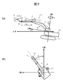
- FIG. 1A and 1B are a side view (a) and a top view (b) of a hydraulic excavator according to a first embodiment
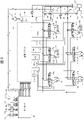
- FIG. 1 is a configuration diagram of a control system for a hydraulic excavator according to a first embodiment
- FIG. FIG. 3 is a diagram showing the detailed configuration of the solenoid valve unit according to the first embodiment
- FIG. FIG. 3 is a diagram showing the detailed configuration of the solenoid valve unit according to the first embodiment
- FIG. 3 is a hardware configuration diagram of a controller of the hydraulic excavator according to the first embodiment
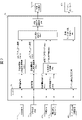
- FIG. 3 is a functional block diagram of a controller according to the first embodiment
- FIG. 4 is a functional block diagram of a state transition determination unit according to the first embodiment;
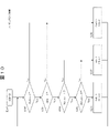
- FIG. 4 is a flowchart of calculations in the state transition unit according to the first embodiment;
- 4 is a flowchart of calculation in an automatic driving start determination unit according to the first embodiment; It is a flowchart of the calculation in the automatic driving
- 4 is a flow chart of calculation in a target motion calculation unit according to the first embodiment;
- FIG. 4 is a diagram showing a normal transition example of the operating state of the hydraulic excavator according to the first embodiment;
- FIG. 5 is a diagram showing an example of transition of the operating state when the hydraulic excavator according to the first embodiment is switched to an automatic operating state and left unattended.
- FIG. 5 is a diagram showing an example of transition of the operating state when the hydraulic excavator according to the first embodiment is switched to an automatic operating state and left unattended.
- FIG. 4 is a diagram showing an example of a transition of an operating state when the hydraulic excavator according to the first embodiment is locked from start-up;
- FIG. 4 is a functional block diagram of a controller according to a modification of the first embodiment;
- FIG. 9 is a flowchart of calculations in the state transition unit according to the modified example of the first embodiment; 9 is a flowchart of calculation in a desired motion calculation unit according to a modification of the first embodiment;
- FIG. 9 is a diagram showing an example of transition of the operating state when the hydraulic excavator according to the first embodiment is switched to an automatic operating state and left unattended.
- FIG. 4 is a diagram showing an example of a transition of an operating state when the hydraulic excavator according to the first embodiment is locked from start-up;
- FIG. 4 is a functional block diagram of
- FIG. 10 is a diagram showing an example of transition of an operating state when the hydraulic excavator is left in an automatic operating state in a modified example of the first embodiment
- FIG. 7 is a configuration diagram of a control system for a hydraulic excavator according to a second embodiment
- FIG. 7 is a hardware configuration diagram of a controller of a hydraulic excavator according to a second embodiment
- FIG. 5 is a functional block diagram of a controller according to a second embodiment
- FIG. 1 is a perspective view showing the configuration of a hydraulic excavator 1 according to the first embodiment.
- the hydraulic excavator 1 includes an articulated front working device 1A, a vehicle body 1B, a controller (not shown in FIG. 1), and a communication device 650.
- the front working device 1A has a boom cylinder 5, an arm cylinder 6, a bucket cylinder 7, a boom 8, an arm 9, a bucket 10, a bucket link 13, a boom angle sensor 30, an arm angle sensor 31 and a bucket angle sensor 32.
- the boom 8, the arm 9, and the bucket 10 are a plurality of driven members that rotate, respectively, and the front working device 1A is configured by connecting them.
- the vehicle body 1B has a lower running body 11 and an upper revolving body 12.
- the lower traveling body 11 travels by being driven by a pair of left and right travel hydraulic motors 3a and 3b.
- the upper rotating body 12 is mounted on the lower running body 11 and is configured to be able to rotate.
- the base end of the boom 8 is rotatably supported at the front part of the upper swing body 12 via a boom pin.
- An arm 9 is rotatably connected to the tip of the boom 8 via an arm pin.
- a bucket 10 is rotatably connected to the tip of the arm 9 via a bucket pin.
- Boom 8 is driven by boom cylinder 5
- arm 9 is driven by arm cylinder 6
- bucket 10 is driven by bucket cylinder 7 .
- FIG. 2(a) is a side view of the hydraulic excavator 1.
- FIG. 2(a) when the X-axis is defined parallel to the longitudinal direction of the undercarriage 11 and the Z-axis is defined perpendicular to the X-axis, the rotation angle of the boom 8 is ⁇ .
- ⁇ be the rotation angle
- ⁇ be the rotation angle of the bucket 10 .
- ⁇ be the inclination angle of the upper revolving structure 12 (the vehicle body 1B) with respect to a reference plane (for example, a horizontal plane).
- P be the tip of the bucket 10 .
- FIG. 2(b) is a top view of the hydraulic excavator 1.
- FIG. 2(b) the relative angle between the upper rotating body 12 and the lower traveling body 11 is ⁇ .
- the boom angle sensor 30 is attached to the boom pin so that the rotation angle ⁇ of the boom 8 can be measured.
- the arm angle sensor 31 is attached to the arm pin so that the rotation angle ⁇ of the arm 9 can be measured.
- the bucket angle sensor 32 is attached to the bucket link 13 so as to measure the rotation angle ⁇ of the bucket 10 .
- the angle sensors 30, 31 and 32 can be replaced with angle sensors for a reference plane (for example, a horizontal plane).
- the upper swing body 12 has an operator's cab 120 , a hydraulic pump 2 , a swing hydraulic motor 4 , an engine 18 , a vehicle body tilt angle sensor 33 , a swing angle sensor 34 and a tank 200 .
- the operator's cab 120 is provided with a right operating lever 22 a , a left operating lever 22 b , a right running lever 23 a , a left running lever 23 b , an engine speed setting device 480 , and an operating state changeover switch 670 .
- the operation right lever 22a and the operation left lever 22b may be referred to as the operation device 22
- the travel right lever 23a and the travel left lever 23b may be referred to as the operation device 23.
- the swing hydraulic motor 4 swings the upper swing body 12 .
- the traveling hydraulic motors 3a and 3b, the turning hydraulic motor 4, the boom cylinder 5, the arm cylinder 6, and the bucket cylinder 7 may be collectively referred to as "actuators".
- the vehicle body tilt angle sensor 33 is attached to an arbitrary position of the upper revolving body 12, and detects the tilt angle ⁇ of the upper revolving body 12 (body 1B) with respect to a reference plane (for example, a horizontal plane).
- the turning angle sensor 34 is provided on the turning center axis of the upper turning body 12 and measures the relative angle ⁇ between the upper turning body 12 and the lower traveling body 11 .
- the driving state changeover switch 670 is a switch for selecting whether to operate the vehicle body based on instructions from the operating devices 22 and 23 or to operate the vehicle body based on the results of automatic operation calculations by the controller. That is, the operating state changeover switch 670 is a switch for switching between an automatic operating state (automatic operating mode) and a manual operating state (manual operating mode). Since the automatic operation state is a state in which the operation devices 22 and 23 are not operated, even if the operation amount input to the operation devices 22 and 23 is 0, the actual operation amount of the actuator is not always 0. state.
- the engine 18 is a prime mover and drives the hydraulic pump 2 and a pilot pump to be described later.
- Engine speed setting device 480 is a device for setting the speed of engine 18 .
- the engine speed setting device 480 is a dial type variable resistor, and the voltage output from the engine speed setting device 480 varies according to the dial operation.
- the communication device 650 transmits and receives signals to and from the remote control device 800.
- the remote control device 800 is a device for remotely starting or stopping automatic operation of the hydraulic excavator 1 and includes a remote start switch 880 .
- a switch state signal of the remote start switch 880 is transmitted to the controller of the hydraulic excavator 1 via the communication device 850 and the communication device 650 .
- automated operation means that the actuator automatically operates according to instructions from the controller even if the operating devices 22 and 23 of the hydraulic excavator 1 are not operated.
- FIG. 3 is a configuration diagram showing the configuration of the control system of the hydraulic excavator 1.
- the control system of the hydraulic excavator 1 includes hydraulic pumps 2a and 2b, flow control valves 15a to 15f, load detection devices 16a to 16f, an engine 18, regulators 21a and 21b, a right operation lever 22a and a left operation lever.
- Lever 22b (operating device 22), right travel lever 23a and left travel lever 23b (operating device 23), gate lock lever 37, lock valve 39, controller 40, operating devices 45a and 45b, operating devices 46a and 46b, operating device 47a , 47b, a pilot pump 48, a pump line 143, pilot lines 144a-149b, hydraulic drive units 150a-155b, an electromagnetic valve unit 160, a tank 200, an engine controller 470, and an engine speed detector 490.
- the operation devices 22 and 23 and the gate lock lever 37 are provided in the driver's cab 120 and operated by the operator.
- the operating devices 22 and 23 are of the electric lever type, and generate electric signals according to the amount and direction of operation by the operator.
- the electric signals generated in this manner are input to the controller 40 via the operating devices 45a to 47b.
- the controller 40 outputs an electric signal to the solenoid valve unit 160 to drive the proportional solenoid valve according to the operation input to the operating devices 22 and 23 .
- the operation devices 45a to 47b are provided inside the operator's cab 120.
- the operation device 47a is connected to the right travel lever 23a and outputs a signal to the controller 40 for operating the right travel hydraulic motor 3a.
- the operation device 47b is connected to the left travel lever 23b and outputs to the controller 40 a signal for operating the left travel hydraulic motor 3b.
- the operation devices 45 a and 46 a are connected to a common right operation lever 22 a and output signals for operating the boom cylinder 5 and bucket cylinder 7 to the controller 40 .
- the operating devices 45b and 46b are connected to a common left operating lever 22b and output signals for operating the arm cylinder 6 and the swing hydraulic motor 4 to the controller 40.
- the engine 18 drives the hydraulic pumps 2a and 2b and the pilot pump 48.
- the hydraulic pumps 2a and 2b are variable displacement pumps whose displacements are controlled by regulators 21a and 21b, respectively.
- Pilot pump 48 is a fixed displacement pump.
- the engine controller 470 controls the engine speed and the like according to the control signal from the controller 40 .
- Engine speed detection device 490 is a rotation sensor for detecting the speed of engine 18 .
- the hydraulic pump 2 and the pilot pump 48 suck hydraulic oil from the tank 200.
- a control signal output from the controller 40 is input to the regulators 21a and 21b.
- the discharge flow rates of the hydraulic pumps 2a and 2b are controlled according to the control signal.
- Pressure oil discharged from the hydraulic pump 2 is supplied to the boom cylinder 5 through the flow control valve 15a, supplied to the arm cylinder 6 through the flow control valve 15b, and supplied to the bucket cylinder 7 through the flow control valve 15c. supplied to the swing hydraulic motor 4 through the flow control valve 15d, supplied to the right traveling hydraulic motor 3a through the flow control valve 15e, and supplied to the left traveling hydraulic motor 3b through the flow control valve 15f. .
- the boom cylinder 5, the arm cylinder 6, and the bucket cylinder 7 are extended and contracted by the supplied pressure oil, so that the boom 8, the arm 9, and the bucket 10 are rotated, and the position and posture of the bucket 10 are changed.
- the hydraulic hydraulic motor 4 is rotated by the supplied pressure oil, so that the upper swing body 12 swings with respect to the lower traveling body 11 . Then, the right traveling hydraulic motor 3a and the left traveling hydraulic motor 3b are rotated by the supplied pressure oil, so that the lower traveling body 11 travels.
- the boom cylinder 5 is provided with load detection devices 16a and 16b
- the arm cylinder 6 is provided with load detection devices 16c and 16d
- the bucket cylinder 7 is provided with load detection devices 16e and 16f. be provided.
- the load detection devices 16a to 16f are pressure sensors that detect the bottom side pressure and the rod side pressure of the boom cylinder 5, the arm cylinder 6, and the bucket cylinder 7, respectively, and send them to the controller 40 as electrical signals. Output. Note that FIG. 3 does not show connection lines from the load detectors 16a to 16f to the controller 40 due to space limitations.
- the pump line 143 is a discharge pipe for the pilot pump 48 , passes through the lock valve 39 , and is connected to each electromagnetic proportional valve in the electromagnetic valve unit 160 .
- the lock valve 39 is an electromagnetic switching valve in this embodiment, and its electromagnetic driving portion is electrically connected to the position detector 38 of the gate lock lever 37 .
- the gate lock lever 37 has a rotation center, and the operator can manually rotate the gate lock lever 37 .
- the gate lock lever 37 can be configured to be rotatable from the angle at which it contacts the upper limit stopper to the angle at which it contacts the lower limit stopper.
- the position detector 38 is a switch sensor, and can have a structure in which the gate lock lever presses the switch at the same time when the gate lock lever hits the lower limit stopper.
- the position detector 38 outputs a signal corresponding to the position of the gate lock lever to the lock valve 39 .
- the lock valve 39 is closed to block the pump line 143, and when it is at the unlocked position, the lock valve 39 is opened to open the pump line 143.
- the operation by the operation devices 22 and 23 is disabled, and operations such as traveling, turning, excavation, etc. are prohibited.
- FIG. 4 and 5 are diagrams showing the detailed configuration of the solenoid valve unit 160.
- the solenoid valve unit 160 is connected to the pilot pump 48 via the pump line 143 on the primary port side.
- the electromagnetic valve unit 160 has electromagnetic proportional valves 54a-59b that reduce the pilot pressure from the pilot pump 48 and output it to the pilot lines 144a-149b.
- the electromagnetic proportional valves 54a-59b are used as control signals for driving the flow control valves 15a-15f according to the input electrical signals.
- the electromagnetic proportional valves 54a and 54b are connected to hydraulic drive units 150a and 150b of the flow control valve 15a via pilot lines 144a and 144b.
- the proportional solenoid valves 55a and 55b are connected via pilot lines 145a and 145b to hydraulic drives 151a and 151b of the flow control valve 15b.
- the proportional solenoid valves 56a and 56b are connected via pilot lines 146a and 146b to hydraulic drives 152a and 152b of the flow control valve 15c.
- the electromagnetic proportional valves 57a and 57b are connected to hydraulic drive units 153a and 153b of the flow control valve 15d via pilot lines 147a and 147b.
- the proportional solenoid valves 58a and 58b are connected via pilot lines 148a and 148b to hydraulic drives 154a and 154b of the flow control valve 15e.
- the proportional solenoid valves 59a and 59b are connected via pilot lines 149a and 149b to hydraulic drives 155a and 155b of the flow control valve 15f.
- the proportional solenoid valves 54a to 59b have the minimum opening when not energized, and the opening increases as the current, which is the control signal from the controller 40, increases. In this manner, the opening degrees of the proportional electromagnetic valves 54a to 59b correspond to the control signals from the controller 40.
- FIG. 1 The proportional solenoid valves 54a to 59b have the minimum opening when not energized, and the opening increases as the current, which is the control signal from the controller 40, increases. In this manner, the opening degrees of the proportional electromagnetic valves 54a to 59b correspond to the control signals from the controller 40.
- pilot pressure can be generated even when the corresponding operating devices 22 and 23 are not operated by the operator.
- the actuator can be forced to operate.
- FIG. 6 is a hardware configuration diagram of the controller 40.
- the controller 40 is a computer device, and includes an input section 91, a central processing unit (CPU) 92 which is a processor, a read only memory (ROM) 93, a random access memory (RAM) 94 and an output section 95.
- CPU central processing unit
- ROM read only memory
- RAM random access memory
- the posture detection device 50 is composed of the boom angle sensor 30, the arm angle sensor 31, the bucket angle sensor 32, the vehicle body tilt angle sensor 33, and the turning angle sensor 34 described above. These angle sensors 30, 31, 32 and 33 function as attitude sensors for the front working device 1A.
- the input unit 91 receives a signal from the posture detection device 50, a signal indicating the amount of operation from the operation devices 22 and 23, a signal from the engine speed setting device 480, a signal from the communication device 650, and a signal from the communication device 650.
- a signal from the switch 670 is input and converted so that the CPU 92 can perform calculations.
- the ROM 93 is a recording medium that stores a control program for executing control contents including processing related to flowcharts to be described later, various information necessary for executing the flowcharts, and the like.
- the CPU 92 performs predetermined arithmetic processing on signals received from the input section 91 , the ROM 93 and the RAM 94 according to the control program stored in the ROM 93 .
- the output unit 95 creates an output signal according to the calculation result of the CPU 92, and outputs the signal to the engine controller 470 and the electromagnetic proportional valves 54a to 59b, thereby controlling the driving of the engine 18 and each actuator. .
- controller 40 of FIG. 6 has semiconductor memories such as ROM 93 and RAM 94 as storage devices, other types of storage devices can be substituted for the storage devices.
- semiconductor memories such as ROM 93 and RAM 94
- other types of storage devices can be substituted for the storage devices.
- a magnetic storage device such as a hard disk drive can be used. It's okay to be prepared.
- FIG. 7 is a functional block diagram of the controller 40.
- the controller 40 includes, as functional modules realized by the CPU 92 executing a control program, a state transition determination section 40a, a target operation calculation section 40b-1 for manual operation, and a target operation calculation section 40b-2 for automatic operation. , a target operation calculation unit 40b-3, a target engine speed calculation unit 40c, and an electromagnetic proportional valve control unit 40d.
- the state transition determination unit 40a receives an automatic operation start command Rs(t), which is a signal transmitted from the communication device 650 and converted by the input unit 91, and It receives the state switching flag Fm(t), which is a signal, and calculates the automatic driving start flag Fs(t) and the driving state information M(t) based on the information. Then, the state transition determination unit 40a transmits the automatic driving start flag Fs(t) and the driving state information M(t) to the target operation calculation unit 40b-3.
- the automatic operation start command Rs(t) is a signal represented by 0 or 1. When the signal is 1, it commands the start of the automatic operation, and when it is 0, it commands the stop of the automatic operation.
- the automatic operation start flag Fs(t) when the automatic operation start flag Fs(t) is 1, it indicates the start of the automatic operation, and when it is 0, it indicates the stop of the automatic operation.
- the state switching flag Fm(t) is a signal represented by 0 or 1. When it is 1, it commands a transition to the automatic operation state, and when it is 0, it commands a transition to the manual operation state. command.
- the driving state information M(t) is a signal represented by 0 or 1. When the signal is 1, it indicates the automatic driving state, and when it is 0, it indicates the manual driving state.
- the manual operation target operation calculation unit 40b-1 receives operation amount information, which is a signal obtained by converting an electric signal corresponding to the operator's operation amount and operation direction transmitted from the operation devices 22 and 23 by the input unit 91. , to calculate the target actuator speed Vmt(t). Then, the manual operation target motion calculation unit 40b-1 transmits information on the target actuator speed Vmt(t) to the target motion calculation unit 40b-3.
- the operation amount information is angle information of each lever.
- the manual operation target motion calculation unit 40b-1 inputs the angle information of each lever to an angle-target actuator speed table (not shown), and outputs the table as a target actuator speed Vmt(t), which is the target speed of each actuator. do.
- the automatic driving target motion calculation unit 40b-2 receives posture information, which is a signal transmitted from the posture detection device 50 and converted by the input unit 91, and computes the target actuator velocity Vat(t). Then, the automatic operation target motion calculation unit 40b-2 transmits information on the target actuator speed Vat(t) to the target motion calculation unit 40b-3.
- the ROM 93 stores the target motion of the hydraulic excavator 1, such as the target trajectory of the tip P of the bucket 10 and the travel route of travel.
- the controller 40 performs feedback control with posture information as input so that the actual motion matches the target motion.
- the target motion calculation unit 40b-3 calculates the target actuator speed Vmt(t) sent from the manual operation target motion calculation unit 40b-1 and the target actuator speed Vat sent from the automatic operation target motion calculation unit 40b-2. (t), the automatic operation start flag Fs(t) and the operating state information M(t) transmitted from the state transition determination unit 40a, and calculates the final target actuator speed. Then, the target motion calculation section 40b-3 outputs the final target actuator speed to the proportional solenoid valve control section 40d.
- the electromagnetic proportional valve control section 40d outputs control command values for the corresponding electromagnetic proportional valves 54 to 59 in accordance with the target actuator speed output from the target motion calculation section 40b-3.
- the target engine speed calculation unit 40c receives an engine speed setting signal, which is a signal obtained by converting the voltage value output from the engine speed setting device 480 and read by the controller 40 by the input unit 91, and calculates the target engine speed. to calculate Then, the target engine speed calculation unit 40 c transmits the target engine speed to the engine controller 470 .
- the engine speed setting signal is a voltage value.
- the target engine speed calculator 40c inputs the voltage value information to a voltage-target engine speed table (not shown), and uses the output as the target engine speed.
- FIG. 8 is a functional block diagram of the state transition determination section 40a.
- the state transition determination unit 40a includes a state transition unit 40a-1, an automatic operation start determination unit 40a-2, an automatic operation operation stop time measurement unit 40a-3, a numerical value storage unit 40a-11, 40a- 21, 40a-31 and 40a-41.
- the automatic driving state cancellation flag Fu(t) is 0, it commands not to cancel the automatic driving state, and when it is 1, it commands to cancel the automatic driving state.
- the automatic driving state cancellation flag Fu(t) is output to the numerical value holding unit 40a-11 and input to the state transition unit 40a-1 in the next control cycle.
- the start lock flag Fl(t) becomes 0 when the operation is performed according to the correct procedure of "sending a signal to start automatic operation after switching from the manual operation state to the automatic operation state". can be started. On the other hand, if the above correct procedure is not followed, it is set to 1 and the start of automatic operation is locked.
- the start lock flag Fl(t) is output to the numerical value holding unit 40a-21 and input to the automatic operation start determination unit 40a-2 in the next control cycle.
- the automatic operation start flag Fs(t), the operation state information M(t), and the automatic operation stop one control period before stored in the numerical value holding unit 40a-31 Automatic operation stop time Ts(t) is measured based on time Ts(t ⁇ t).
- the automatic operation stop time Ts(t) is output to the numerical holding unit 40a-31, and is input to the state transition unit 40a-1 and the automatic operation stop time measurement unit 40a-3 in the next control cycle.
- FIG. 9 is a flow chart of operations in the state transition section 40a-1. It is assumed that the sampling time of the controller 40 is .DELTA.t, and the calculation is performed every control cycle. This operation flow is repeatedly processed while the controller 40 is operating, for example. Steps S101 to S107 shown in FIG. 9 are set as one control cycle.
- Step S101 The state transition unit 40a-1 starts computation.
- Step S102 The state transition unit 40a-1 determines whether the state change flag Fm(t) is 1 or not. When the state switching flag Fm(t) is 1, it is determined as Yes in step S102, and the process proceeds to step S103. When the state switching flag Fm(t) is 0, it is determined as No in step S102, and the process proceeds to S107.
- Step S103 The state transition unit 40a-1 determines whether or not the automatic operation state cancellation flag Fu(t ⁇ t) one control period before is zero. If the automatic driving state release flag Fu(t ⁇ t) one control period before is 0, the determination in step S103 is YES, and the process proceeds to step S104. If the automatic driving state cancellation flag Fu(t ⁇ t) one control period before is 1, the determination in step S103 is No, and the process proceeds to step S106.
- Step S104 The state transition unit 40a-1 determines whether or not the automatic operation stop time Ts (t ⁇ t) one control cycle before is smaller than the threshold Tth (predetermined time). If the automatic operation stop time Ts (t ⁇ t) one control cycle before is smaller than the threshold value Tth seconds, the determination in step S104 is Yes, and the process proceeds to step S105. If the automatic operation stop time Ts (t ⁇ t) one control period before is equal to or longer than the threshold value Tth seconds, the determination in step S104 is No, and the process proceeds to step S106.
- Step S105 The state transition unit 40a-1 determines to transition to the automatic driving state, sets the driving state information M(t) to 1, and sets the automatic driving state cancellation flag Fu(t) to 0. Then, the information is output from the state transition section 40a-1.
- Step S106 The state transition unit 40a-1 determines that the automatic operation state has been left unattended for a predetermined time or more, so that the state transitions to the manual operation state, sets the operation state information M(t) to 0, and sets the automatic operation state cancellation flag Fu(t). is set to 1. Then, the information is output from the state transition section 40a-1.
- Step S107 The state transition unit 40a-1 determines to transition to the manual operation state, sets the operation state information M(t) to 0, and sets the automatic operation state cancellation flag Fu(t) to 0. Then, the information is output from the state transition section 40a-1.
- FIG. 10 is a flowchart of calculations in the automatic driving start determination unit 40a-2. This operation flow is repeatedly processed while the controller 40 is operating, for example. Steps S201 to S208 shown in FIG. 10 are set as one control cycle.
- Step S201 The automatic driving start determination unit 40a-2 starts calculation.
- Step S202 The automatic operation start determination unit 40a-2 determines whether the automatic operation start command Rs(t) is 1 or not. When the automatic operation start command Rs(t) is 1, it is determined as Yes in step S202, and the process proceeds to step S203. When the automatic operation start command Rs(t) is 0, it is determined as No in step S202, and the process proceeds to step S208.
- Step S203 The automatic driving start determination unit 40a-2 determines whether the driving state information M(t) is 1 or not. When the driving state information M(t) is 1, it is determined as Yes in step S203, and the process proceeds to step S204. If the operating state information M(t) is 0, the determination in step S203 is No, and the process proceeds to step S208.
- Step S204 The automatic driving start determination unit 40a-2 determines whether or not the driving state information M(t ⁇ t) one control cycle before is 1. If the operating state information M(t ⁇ t) one control period before is 1, the determination in step S204 is YES, and the process proceeds to step S205. If the operating state information M(t ⁇ t) one control period before is 0, the determination in step S204 is No, and the process proceeds to step S207.
- Step S205 The automatic driving start determination unit 40a-2 determines whether or not the start lock flag Fl(t ⁇ t) one control cycle before is 0. If the starting lock flag Fl(t- ⁇ t) one control period before is 0, the determination in step S205 is YES, and the process proceeds to step S206. If the starting lock flag Fl(t- ⁇ t) one control period before is 1, the determination in step S205 is No, and the process proceeds to step S207.
- Step S206 The automatic driving start determination unit 40a-2 determines that the automatic driving start command Rs(t) becomes 1 after entering the automatic driving state, and the automatic driving start flag Fs(t) is set to 1. , and the start lock flag Fl(t) is set to 0. Then, the automatic driving start determination unit 40a-2 outputs these values.
- Step S207 The automatic operation start determination unit 40a-2 determines that the automatic operation start command Rs(t) is 1 and the automatic operation start command has been issued, and the automatic operation start flag Fs is determined. (t) is set to 0, and the start lock flag Fl(t) is set to 1. Then, the automatic driving start determination unit 40a-2 outputs these values.
- Step S208 The automatic driving start determination unit 40a-2 determines that the automatic driving state is not set or that the automatic driving start command Rs(t) does not command the start of automatic driving, and sets the automatic driving start flag Fs(t). 0, and the start lock flag Fl(t) is set to 0. Then, the automatic driving start determination unit 40a-2 outputs these values.
- FIG. 11 is a flow chart of calculations in the automatic operation stop time measuring section 40a-3. This operation flow is repeatedly processed while the controller 40 is operating, for example. Steps S301 to S305 shown in FIG. 11 are set as one control cycle.
- Step S301 The automatic operation stop time measurement unit 40a-3 starts calculation.
- Step S302 The automatic driving operation stop time measurement unit 40a-3 determines whether the driving state information M(t) is 1 or not. When the driving state information M(t) is 1, it is determined as Yes in step S302, and the process proceeds to step S303. If the operating state information M(t) is 0, the determination in step S302 is No, and the process proceeds to step S305.
- Step S303 The automatic driving operation stop time measurement unit 40a-3 determines whether the automatic driving start flag Fs(t) is zero. When the automatic driving start flag Fs(t) is 0, it is determined as Yes in step S303, and the process proceeds to step S304. When the automatic operation start flag Fs(t) is 1, it is determined as No in step S303, and the process proceeds to step S305.
- Step S304 The automatic operation operation stop time measurement unit 40a-3 determines that the automatic operation start command is not issued even though the automatic operation state is set, and the automatic operation operation stop time Ts (t ⁇ t) one control cycle before The value obtained by adding the sampling time ⁇ t to the automatic operation stop time Ts(t). Then, the automatic operation stop time measuring section 40a-3 outputs this value.
- Step S305 The automatic operation stop time measurement unit 40a-3 determines that the automatic operation state is not the state or the automatic operation state and the operating state, and sets the automatic operation stop time Ts(t) to 0. Then, the automatic operation stop time measuring section 40a-3 outputs this value.
- FIG. 12 is a flow chart of calculations in the target motion calculator 40b-3. It is assumed that the sampling time of the controller 40 is .DELTA.t, and the calculation is performed every control cycle.
- Step S401 The target motion calculation unit 40b-3 starts calculation.
- Step S402 The target motion calculation unit 40b-3 determines whether the driving state information M(t) is 1 or not. If the operating state information M(t) is 1, the determination in step S402 is Yes, and the process proceeds to step S403. If the operating state information M(t) is 0, the determination in step S402 is No, and the process proceeds to step S406.
- Step S403 The target operation calculation unit 40b-3 determines whether or not the automatic operation start flag Fs(t) is zero. When the automatic driving start flag Fs(t) is 0, it is determined as Yes in step S403, and the process proceeds to step S404. When the automatic operation start flag Fs(t) is 1, it is determined as No in step S403, and the process proceeds to step S405.
- Step S404 The target motion calculation unit 40b-3 determines that the automatic operation start command is not issued even though the automatic operation state is set, and sets the final target actuator speed to zero. Then, the target operation calculation section 40b-3 outputs this value to the electromagnetic proportional valve control section 40d.
- Step S405 The target motion calculation unit 40b-3 determines that the automatic operation state is in effect and that the automatic operation start command has been issued, and sets the final target actuator speed to Vat(t). Then, the target operation calculation section 40b-3 outputs this value to the electromagnetic proportional valve control section 40d.
- Step S406 The target motion calculation unit 40b-3 determines that the manual operation state is set, and sets the final target actuator speed to Vmt(t). Then, the target operation calculation section 40b-3 outputs this value to the electromagnetic proportional valve control section 40d.
- FIG. 13 is a diagram showing a normal transition example of the operating state of the hydraulic excavator 1.
- the normal transition of the operation state of the hydraulic excavator 1 means that the automatic operation start command is issued within a predetermined time (threshold value Tth seconds) after the manual operation state is switched to the automatic operation state by operating the operation state changeover switch 670 .
- Tth seconds a predetermined time
- the horizontal axis indicates the passage of time.
- the vertical axis represents the state of the state switching flag Fm(t) transmitted from the operating state switching switch 670, the state of the automatic operation start command Rs(t) transmitted from the communication device 650, and the operating state information M ( t) and the operating state of the hydraulic excavator, respectively.
- step S107 in FIG. 9 the output of the state transition unit 40a-1 becomes as shown in step S107 in FIG. 9 (S102 ⁇ S107). That is, the driving state information M(t) is set to 0, and the automatic driving state release flag Fu(t) is set to 0.
- step S208 the output of the automatic operation start determination unit 40a-2 is as shown in step S208 in FIG. 10 (S202 ⁇ S208). That is, the automatic operation start flag Fs(t) is set to 0, and the start lock flag Fl(t) is set to 0.
- the output of the automatic operation stop time measurement unit 40a-3 is as shown in step S305 of FIG. 11 (S302 ⁇ S305). That is, the automatic operation stop time Ts(t) remains zero.
- the output of the target motion calculation unit 40b-3 is as shown in step S406 in FIG. 12 (S402 ⁇ S406). That is, the final target actuator velocity is set to the value of Vmt(t).
- the operating state of the hydraulic excavator is the manual operating state, and the hydraulic excavator 1 operates according to the lever inputs of the operating devices 22 and 23.
- step S105 in FIG. 9 the output of the state transition unit 40a-1 becomes as shown in step S105 in FIG. 9 (S102 ⁇ S103 ⁇ S104 ⁇ S105). That is, the driving state information M(t) is set to 1. Further, the automatic driving state cancellation flag Fu(t) is set to zero.
- step S208 the output of the automatic operation start determination unit 40a-2 is as shown in step S208 in FIG. 10 (S202 ⁇ S208). That is, the automatic operation start flag Fs(t) is set to 0, and the start lock flag Fl(t) is set to 0.
- the output of the automatic operation stop time measurement unit 40a-3 is as shown in step S304 in FIG. 11 ( S302 ⁇ S303 ⁇ S304). That is, the automatic operation stop time Ts(t) is added.
- the output of the target motion calculation unit 40b-3 is as shown in step S404 of FIG. 12 (S402 ⁇ S403 ⁇ S404). That is, the final target actuator velocity is set to zero.
- the operating state of the hydraulic excavator is the automatic operating state, and the hydraulic excavator 1 does not operate.
- step S105 in FIG. 9 the output of the state transition unit 40a-1 becomes as shown in step S105 in FIG. 9 (S102 ⁇ S103 ⁇ S104 ⁇ S105). That is, the driving state information M(t) is set to 1. Further, the automatic driving state cancellation flag Fu(t) is set to zero.
- the output of the automatic driving start determination unit 40a-2 becomes as shown in step S206 in FIG. 10 (S202 ⁇ S203 ⁇ S204 ⁇ S205 ⁇ S206). That is, the automatic operation start flag Fs(t) is set to 1, and the start lock flag Fl(t) is set to 0.
- the output of the automatic operation stop time measurement unit 40a-3 is as shown in step S305 of FIG. 11 ( S302 ⁇ S303 ⁇ S305). That is, the automatic operation stop time Ts(t) is set to zero.
- the output of the target motion calculation unit 40b-3 is as shown in step S405 of FIG. 12 (S402 ⁇ S403 ⁇ S405). That is, the final target actuator velocity is set to Vat(t).
- the operating state of the hydraulic excavator is the automatic operating state, and the hydraulic excavator 1 operates automatically.
- FIG. 14 is a diagram showing a transition example of the operating state when the hydraulic excavator 1 is left after being switched to the automatic operating state.
- FIG. 14 shows up to time t5.
- step S107 in FIG. 9 the output of the state transition unit 40a-1 becomes as shown in step S107 in FIG. 9 (S102 ⁇ S107). That is, the driving state information M(t) is set to 0, and the automatic driving state release flag Fu(t) is set to 0.
- step S208 the output of the automatic operation start determination unit 40a-2 is as shown in step S208 in FIG. 10 (S202 ⁇ S208). That is, the automatic operation start flag Fs(t) is set to 0, and the start lock flag Fl(t) is set to 0.
- the output of the automatic operation stop time measurement unit 40a-3 is as shown in step S305 of FIG. 11 (S302 ⁇ S305). That is, the automatic operation stop time Ts(t) remains zero.
- the output of the target motion calculation unit 40b-3 is as shown in step S406 in FIG. 12 (S402 ⁇ S406). That is, the final target actuator velocity is set to the value of Vmt(t).
- the operating state of the hydraulic excavator is the manual operating state, and the hydraulic excavator 1 operates according to the lever inputs of the operating devices 22 and 23.
- step S105 in FIG. 9 the output of the state transition unit 40a-1 becomes as shown in step S105 in FIG. 9 (S102 ⁇ S103 ⁇ S104 ⁇ S105). That is, the driving state information M(t) is set to 1. Further, the automatic driving state cancellation flag Fu(t) is set to zero.
- step S208 the output of the automatic operation start determination unit 40a-2 is as shown in step S208 in FIG. 10 (S202 ⁇ S208). That is, the automatic operation start flag Fs(t) is set to 0, and the start lock flag Fl(t) is set to 0.
- the output of the automatic operation stop time measurement unit 40a-3 is as shown in step S304 in FIG. 11 ( S302 ⁇ S303 ⁇ S304). That is, the automatic operation stop time Ts(t) is added.
- the output of the target motion calculation unit 40b-3 is as shown in step S404 of FIG. 12 (S402 ⁇ S403 ⁇ S404). That is, the final target actuator velocity is set to zero.
- the operating state of the hydraulic excavator 1 is the automatic operating state, and the hydraulic excavator 1 does not operate.
- the output of the state transition unit 40a-1 becomes as shown in step S106 in FIG. 9 (S102 ⁇ S103 ⁇ S104 ⁇ S106). That is, the operating state information M(t) is set to zero. Further, the automatic driving state release flag Fu(t) is set to one. Thereafter, until the state switching flag Fm(t) is switched to 0, the output of the state transition section 40a-1 is as shown in step S106 in FIG. 9 (S102 ⁇ S103 ⁇ S106). That is, the state in which the operating state information M(t) is set to 0 continues. Further, the state in which the automatic driving state cancellation flag Fu(t) is set to 1 is continued.
- step S208 the output of the automatic operation start determination unit 40a-2 is as shown in step S208 in FIG. 10 (S202 ⁇ S208). That is, the automatic operation start flag Fs(t) is set to 0, and the start lock flag Fl(t) is set to 0.
- the output of the automatic operation stop time measurement unit 40a-3 is as shown in step S305 of FIG. 11 (S302 ⁇ S305). That is, the automatic operation stop time Ts(t) is set to zero.
- the output of the target motion calculation unit 40b-3 is as shown in step S406 in FIG. 12 (S402 ⁇ S406). That is, the final target actuator velocity is set to Vmt(t).
- the operating state of the hydraulic excavator is the manual operating state, and the hydraulic excavator 1 operates according to the lever inputs of the operating devices 22 and 23.
- step S106 the output of the state transition section 40a-1 is as shown in step S106 in FIG. 9 (S102 ⁇ S103 ⁇ S106). That is, the state in which the operating state information M(t) is set to 0 continues. Further, the state in which the automatic driving state cancellation flag Fu(t) is set to 1 is continued.
- the automatic driving start command Rs(t) is switched to 1
- the driving state information M(t) is 0, so the output of the automatic driving start determination unit 40a-2 becomes as shown in step S208 in FIG. S202 ⁇ S203 ⁇ S208). That is, the automatic operation start flag Fs(t) is set to 0, and the start lock flag Fl(t) is set to 0.
- the output of the automatic operation stop time measurement unit 40a-3 is as shown in step S305 of FIG. 11 (S302 ⁇ S305). That is, the automatic operation stop time Ts(t) is set to zero.
- the output of the target motion calculation unit 40b-3 is as shown in step S406 in FIG. 12 (S402 ⁇ S406). That is, the final target actuator velocity is set to Vmt(t).
- the operating state of the hydraulic excavator 1 is the manual operating state, and the hydraulic excavator 1 operates according to the lever inputs of the operating devices 22 and 23.
- FIG. 15 is a diagram showing a transition example of the operating state when the hydraulic excavator 1 is left in the automatic operating state.
- FIG. 15 shows the time after time t4.
- the automatic operation start command Rs(t) is switched to 0 at time t5.
- step S106 the output of the state transition section 40a-1 is as shown in step S106 in FIG. 9 (S102 ⁇ S103 ⁇ S106). That is, the state in which the operating state information M(t) is set to 0 continues. Further, the state in which the automatic driving state cancellation flag Fu(t) is set to 1 is continued.
- step S208 in FIG. 10 S202 ⁇ S208. That is, the automatic operation start flag Fs(t) is set to 0, and the start lock flag Fl(t) is set to 0.
- the output of the automatic operation stop time measurement unit 40a-3 is as shown in step S305 of FIG. 11 (S302 ⁇ S305). That is, the automatic operation stop time Ts(t) is set to zero.
- the output of the target motion calculation unit 40b-3 is as shown in step S406 in FIG. 12 (S402 ⁇ S406). That is, the final target actuator velocity is set to Vmt(t).
- the operating state of the hydraulic excavator 1 is the manual operating state, and the hydraulic excavator 1 operates according to the lever inputs of the operating devices 22 and 23.
- step S107 in FIG. 9 S102 ⁇ S107
- the operating state information M(t) is set to zero.
- the automatic driving state cancellation flag Fu(t) is set to zero.
- step S208 the output of the automatic operation start determination unit 40a-2 is as shown in step S208 in FIG. 10 (S202 ⁇ S208). That is, the automatic operation start flag Fs(t) is set to 0, and the start lock flag Fl(t) is set to 0.
- the output of the automatic operation stop time measurement unit 40a-3 is as shown in step S305 of FIG. 11 (S302 ⁇ S305). That is, the automatic operation stop time Ts(t) is set to zero.
- the output of the target motion calculation unit 40b-3 is as shown in step S406 in FIG. 12 (S402 ⁇ S406). That is, the final target actuator velocity is set to Vmt(t).
- the operating state of the hydraulic excavator 1 is the manual operating state, and the hydraulic excavator 1 operates according to the lever inputs of the operating devices 22 and 23.
- the automatic operation state cancellation flag Fu(t) is reset to 0, it is possible to switch to automatic operation by performing an appropriate operation again within an appropriate time. In other words, the transition to the automatic operation state does not occur until the state switching flag Fm(t), which is the operating state switching signal, is changed at least once.
- the automatic driving start determination unit 40a-2 determines whether or not to lock the start of automatic driving (moving to step S207 and setting the start lock flag Fl(t) to 1). No) is determined. The effect of performing such processing will be described below.
- FIG. 16 is a diagram showing a transition example of the operating state when the hydraulic excavator 1 is locked from starting.
- FIG. 16 shows the time after time t7.
- step S107 in FIG. 9 the output of the state transition unit 40a-1 becomes as shown in step S107 in FIG. 9 (S102 ⁇ S107). That is, the driving state information M(t) is set to 0, and the automatic driving state release flag Fu(t) is set to 0.
- the output of the automatic driving start determination unit 40a-2 is as shown in step S208 in FIG. 10 (S202 ⁇ S203 ⁇ S208). That is, the automatic operation start flag Fs(t) is set to 0, and the start lock flag Fl(t) is set to 0.
- the output of the automatic operation stop time measurement unit 40a-3 is as shown in step S305 of FIG. 11 (S302 ⁇ S305). That is, the automatic operation stop time Ts(t) remains zero.
- the output of the target motion calculation unit 40b-3 is as shown in step S406 in FIG. 12 (S402 ⁇ S406). That is, the final target actuator velocity is set to the value of Vmt(t).
- the operating state of the hydraulic excavator 1 is the manual operating state, and the hydraulic excavator 1 operates according to the lever inputs of the operating devices 22 and 23.
- step S105 the driving state information M(t) is set to 1, and the automatic driving state release flag Fu(t) is set to 0.
- the automatic operation start command Rs(t) is 1, the operating state information M(t) is 1, and the operating state one control cycle before. Since the information M(t ⁇ t) is 0, the output of the automatic driving start determination unit 40a-2 is as shown in step S207 in FIG. 10 (S202 ⁇ S203 ⁇ S204 ⁇ S207). That is, the automatic operation start flag Fs(t) is set to 0, and the start lock flag Fl(t) is set to 1.
- the output of the automatic operation stop time measurement unit 40a-3 is as shown in step S304 in FIG. 11 ( S302 ⁇ S304). That is, the automatic operation stop time Ts(t) is added.
- the output of the target motion calculation unit 40b-3 is as shown in step S404 of FIG. 12 (S402 ⁇ S403 ⁇ S404). That is, the final target actuator velocity is set to zero.
- the output of the state transition unit 40a-1 continues to select step S105 in FIG. 9 until the threshold Tth seconds have elapsed from time t8 (S102 ⁇ S103 ⁇ S104 ⁇ S105). That is, the driving state information M(t) is set to 1, and the automatic driving state release flag Fu(t) is set to 0.
- the automatic operation start command Rs(t) is 1, the operating state information M(t) is 1, the operating state information M(t ⁇ t) one control period before is 1, and one control is performed. Since the start lock flag Fl (t ⁇ t) before the cycle is 1, the output of the automatic operation start determination unit 40a-2 is as shown in step S207 in FIG. 10 (S202 ⁇ S203 ⁇ S204 ⁇ S205 ⁇ S207). . That is, the automatic operation start flag Fs(t) is set to 0, and the start lock flag Fl(t) continues to be set to 1.
- the output of the automatic operation stop time measurement unit 40a-3 is as shown in step S304 in FIG. 11 ( S302 ⁇ S304). That is, the automatic operation stop time Ts(t) is added.
- the output of the target motion calculation unit 40b-3 is as shown in step S404 of FIG. 12 (S402 ⁇ S403 ⁇ S404). That is, the final target actuator velocity is set to zero.
- the operating state of the hydraulic excavator 1 is the automatic operating state, and the hydraulic excavator 1 does not operate.
- the output of the state transition unit 40a-1 becomes like step S106 in FIG. 9 (S102 ⁇ S103 ⁇ S104 ⁇ S106). That is, the operating state information M(t) is set to zero. Further, the automatic driving state release flag Fu(t) is set to one. After that, the output of the state transition unit 40a-1 continues to select step S106 in FIG. 9 (S102 ⁇ S103 ⁇ S106). That is, the state in which the operating state information M(t) is set to 0 continues. Further, the state in which the automatic driving state cancellation flag Fu(t) is set to 1 is continued.
- step S208 the output of the automatic driving start determination unit 40a-2 is as shown in step S208 in FIG. 10 (S202 ⁇ S203 ⁇ S208). That is, the automatic operation start flag Fs(t) is set to 0, and the start lock flag Fl(t) is set to 0.
- the output of the automatic operation stop time measurement unit 40a-3 is as shown in step S305 of FIG. 11 (S302 ⁇ S305). That is, the automatic operation stop time Ts(t) is set to zero.
- the output of the target motion calculation unit 40b-3 is as shown in step S406 in FIG. 12 (S402 ⁇ S406). That is, the final target actuator velocity is set to Vmt(t).
- the operating state of the hydraulic excavator 1 is the manual operating state, and the hydraulic excavator 1 operates according to the lever inputs of the operating devices 22 and 23.
- the start lock flag Fl(t) is set to 1 when the correct procedure of "transmitting a signal to start automatic operation after switching from the manual operation state to the automatic operation state" is not followed. Driving start is locked. Therefore, the operation is not automatically started at the instant when the state switching flag Fm(t) becomes 1 while the automatic operation start command Rs(t) remains 1. As a result, it is possible to prevent the automatic operation from being started at a timing unexpected by surrounding workers.
- the controller 40 of the hydraulic excavator 1 determines whether or not to transition to the automatic operation state by the state switching flag Fm(t), and after transitioning to the automatic operation state, the threshold value
- the automatic operation start command Rs(t) becomes 1 within Tth seconds (predetermined time)
- automatic operation of the actuator is executed, and automatic operation is performed within threshold Tth seconds (predetermined time) after transition to the automatic operation state. If the operation start command Rs(t) does not become 1, automatic operation is not executed. More specifically, when the hydraulic excavator 1 is left for threshold Tth seconds without issuing a command to start automatic operation in the automatic operation state, the automatic operation state is canceled. As a result, when the automatic operation state is left as it is, the probability that the automatic operation is started at a timing unexpected by the operator or surrounding workers can be reduced.
- FIG. 17 is a functional block diagram of the controller 40 according to the first modified example. As shown in FIG. 17, in this modification, the automatic driving state cancellation flag Fu(t) is output from the state transition determination unit 40a and input to the target operation calculation unit 40b-3. embodiment (FIG. 7).
- FIG. 18 is a flowchart of calculations in the state transition section 40a-1 according to the first modification.
- the processing of step S106 by the state transition section 40a-1 is different from that of the first embodiment. That is, the state transition unit 40a-1 determines that the vehicle has been left in the automatic operation state for a certain period of time or more, sets the operation state information M(t) to 1, and sets the automatic operation state release flag Fu(t) to 1. . Then, the information is output from the state transition section 40a-1.
- FIG. 19 is a flow chart of computation in the desired motion computation unit 40b-3 according to the first modification.
- the process of the desired motion calculation unit 40b-3 is different from the first embodiment in that the process proceeds to step S407 when it is determined as No in step S403.
- the target motion calculation unit 40b-3 determines whether or not the automatic driving state cancellation flag Fu(t) is 1.
- the automatic driving state cancellation flag Fu(t) is 1, it is determined as Yes in step S407, and the process proceeds to step S404.
- the automatic driving state cancellation flag Fu(t) is 0, it is determined as No in step S403, and the process proceeds to step S405.
- FIG. 20 is a diagram showing a transition example of the operating state when the hydraulic excavator 1 is left in the automatic operating state in the first modified example.
- time t1 to time t3 The process up to time t3 is the same as in the first embodiment.
- the output of the state transition unit 40a-1 becomes as shown in step S106 in FIG. 18 (S102 ⁇ S103 ⁇ S104 ⁇ S106). That is, the driving state information M(t) is set to 1, and the automatic driving state release flag Fu(t) is set to 1.
- step S208 the output of the automatic operation start determination unit 40a-2 is as shown in step S208 in FIG. 10 (S202 ⁇ S203 ⁇ S208). That is, the automatic operation start flag Fs(t) is set to 0, and the start lock flag Fl(t) is set to 0. Also, the output of the target motion calculation unit 40b-3 is as shown in step S404 of FIG. 19 (S402 ⁇ S403 ⁇ S404). That is, the final target actuator velocity is set to zero.
- the automatic operation start command Rs(t) becomes 1, and the output of the automatic operation start determination unit 40a-2 becomes like step S206 in FIG. 10 (S202 ⁇ S203 ⁇ S204 ⁇ S205 ⁇ S206).
- the automatic driving start flag Fs(t) is 0, the driving state information M(t) is 1, and the automatic driving state release flag Fu(t) is 1, the target operation calculation unit 40b-3
- the output is as shown in step S404 in FIG. 19 (S402 ⁇ S403 ⁇ S407 ⁇ S404). That is, the final target actuator velocity is set to zero.
- the target speed of the actuator is set to 0 if the automatic operation state is left without a command to start automatic operation. Therefore, it is possible to reduce the probability that the automatic operation is started at a timing unexpected by the surrounding workers when the automatic operation state is left as it is.
- the lock valve 39 is controlled by the operation of the gate lock lever 37 by the operator.
- the controller 40 may be configured to control the lock valve 39 .
- the lock valve 39 is closed to stop the supply of pressure oil to the electromagnetic valve unit 160, and the hydraulic drive units 150a to 155b of the flow control valves 15a to 15f can be set to 0 to stop the supply of pressure oil to the actuator. Even with such an operation, the same effect as in the first embodiment can be obtained.
- the automatic operation state cancellation flag Fu(t) is input to the target engine speed calculation unit 40c, and when the automatic operation state cancellation flag Fu(t) is 1, the target engine speed is controlled to be 0. You may make it
- the remote control device 800 may be provided with a lever (manipulation amount input device) for operating the actuator, and the actuator may operate according to the input of the lever.
- the actuator in the automatic operation state, even if the amount of movement input to the operation devices 22 and 23 is 0, the actuator operates according to the operation of the lever provided on the remote control device 800, so the actual amount of movement of the actuator is not 0.
- the target motion calculation unit 40b-2 for automatic driving to a target motion calculation unit for remote control. That is, the remote control target motion calculation unit executes the processing of the automatic driving target motion calculation unit 40b-2.
- the controller 40 may include both the automatic driving target motion calculation section 40b-2 and the remote control target motion calculation section.
- FIG. 21 is a configuration diagram of a hydraulic excavator control system according to the second embodiment.
- the control system according to the second embodiment differs from the first embodiment in that an LED 300 (informing device) is electrically connected to the controller 40 .
- the controller 40 controls lighting and extinguishing of the LED 300 by changing the current supplied to the LED 300 .
- the LED 300 is mounted, for example, above the driver's cab 120 to notify the outside of the vehicle of the driving state.
- FIG. 22 is a hardware configuration diagram of a hydraulic excavator controller according to the second embodiment.
- an LED 300 is added to the control system, the output unit 95 generates an output signal according to the calculation result of the CPU 92, and the signal is sent to the LED 300. It differs from the first embodiment in that it outputs to control the LED 300 .
- FIG. 23 is a functional block diagram of the controller 40 according to the second embodiment. As shown in FIG. 23, in the second embodiment, a notification device control unit 40e is added, and the operating state information M(t) is input to the notification device control unit 40e. 1 embodiment.
- the notification device control unit 40e determines to turn off the LED 300 when the operating state information M(t) is 0, that is, in the manual operating state, and determines that the LED 300 is turned off when the operating state information M(t) is 1, that is, in the automatic operating state. It is determined to light the LED 300 . Then, a corresponding control command value is output so that the LED 300 is lit or extinguished according to the determination.
- the LED 300 has been described as being mounted above the operator's cab 120 , it may be provided within the operator's cab 120 . In another form, the LED 300 may be controlled to light up (notify) when the controller cancels the automatic driving state. Alternatively, LED 300 may be attached to remote control 800 . In this case, the lighting command is transmitted via the communication device 850 and the communication device 650 . Alternatively, a combination of these may be installed.
- the notification device may be, for example, an audio output device such as a buzzer, or an image output device such as a monitor, in addition to the LED.
- the present disclosure is not limited to the embodiments described above, and includes various modifications.
- the above-described embodiments have been described in detail in order to explain the present disclosure in an easy-to-understand manner, and do not necessarily include all the configurations described.
- part of an embodiment can be replaced with the configuration of another embodiment.
- the configuration of another embodiment can be added to the configuration of one embodiment.
- a part of the configuration of each embodiment can be added, deleted or replaced with a part of the configuration of another embodiment.
Landscapes
- Engineering & Computer Science (AREA)
- Mining & Mineral Resources (AREA)
- Civil Engineering (AREA)
- General Engineering & Computer Science (AREA)
- Structural Engineering (AREA)
- Mechanical Engineering (AREA)
- Operation Control Of Excavators (AREA)
Abstract
自動運転建設機械において、オペレータや周囲の作業者が予期していないタイミングで自動運転が開始される確率を低減する。本開示の自動運転建設機械は、作業装置と、前記作業装置を駆動する複数のアクチュエータを有する車体と、前記複数のアクチュエータの動作を制御するコントローラと、を備え、前記コントローラは、前記複数のアクチュエータを自動運転する自動運転状態に遷移する信号が入力され、所定時間以内に前記複数のアクチュエータの自動運転を始動する信号が入力された場合に、前記複数のアクチュエータの動作を制御して前記自動運転を実行し、前記自動運転状態に遷移する信号が入力されてから前記所定時間以内に前記自動運転を始動する信号が入力されなかった場合には、前記自動運転を実行しない。
Description
本開示は、自動運転建設機械に関する。
建設機械は、土木工事のみならず様々な作業で使用されている。近年では半自動又は自動で作業を行う自動運転建設機械の開発が進んでいる。こういった自動運転建設機械は、オペレータが実施しなければならない操作の量を低減することができるので、オペレータの負担が減り、労働環境の改善につながると期待されている。
特許文献1は、建設機械の自動運転を開始(始動)する方法として、オペレータが搭乗しており、スイッチなどのインターフェースに自動運転の開始を入力した場合に、自動運転を開始する技術を開示している。
特許文献1では、建設機械にオペレータが搭乗している状態で自動運転が開始される。これに加えて、オペレータが建設機械に搭乗していない状態においても自動運転を実施可能とする形態も考えられる。具体的には、手動運転状態から自動運転状態(自動運転モード)に切り替えた後にオペレータが建設機械から降車し、建設機械から離れた位置から、リモコンなどで自動運転の始動指令を送信することで建設機械が自動運転を開始する形態があり得る。このような制御システムにおいては、建設機械が自動運転状態ではあるが動作は開始していない状態が存在する。
ここで、オペレータが、自動運転状態かつ動作していない状態のまま建設機械を放置してしまい、建設機械が自動運転状態であることを忘れる状況が想定される。このような状況でオペレータが誤ってリモコン操作をして自動運転の始動指令を送信した場合、周囲の作業者が予期していないタイミングで建設機械の動作が開始されてしまう恐れがある。
そこで、本開示は、自動運転状態になっている場合に周囲の作業者が予期していないタイミングで自動運転が開始される確率を低減する自動運転建設機械を提供する。
本開示の自動運転建設機械は、作業装置と、前記作業装置を駆動する複数のアクチュエータを有する車体と、前記複数のアクチュエータの動作を制御するコントローラと、を備え、前記コントローラは、前記複数のアクチュエータを自動運転する自動運転状態に遷移する信号が入力され、所定時間以内に前記複数のアクチュエータの自動運転を始動する信号が入力された場合に、前記複数のアクチュエータの動作を制御して前記自動運転を実行し、前記自動運転状態に遷移する信号が入力されてから前記所定時間以内に前記自動運転を始動する信号が入力されなかった場合には、前記自動運転を実行しないことを特徴とする。
本開示の技術によれば、自動運転状態で自動運転が開始されないまま建設機械が放置された場合に、遠隔操作がなされても、自動運転が開始されない。そのため、周囲の作業者が予期していないタイミングで自動運転が開始されることを低減できる。
[第1の実施形態]
<油圧ショベルの構成例>
図1は、第1の実施形態に係る油圧ショベル1の構成を示す斜視図である。油圧ショベル1は、多関節型のフロント作業装置1Aと、車体1Bと、コントローラ(図1には不図示)と、通信装置650と、を備える。
<油圧ショベルの構成例>
図1は、第1の実施形態に係る油圧ショベル1の構成を示す斜視図である。油圧ショベル1は、多関節型のフロント作業装置1Aと、車体1Bと、コントローラ(図1には不図示)と、通信装置650と、を備える。
フロント作業装置1Aは、ブームシリンダ5、アームシリンダ6、バケットシリンダ7、ブーム8、アーム9、バケット10、バケットリンク13、ブーム角度センサ30、アーム角度センサ31及びバケット角度センサ32を有する。ブーム8、アーム9及びバケット10は、それぞれ回動する複数の被駆動部材であり、フロント作業装置1Aは、これらを連結することにより構成されている。
車体1Bは、下部走行体11及び上部旋回体12を有する。下部走行体11は、左右一対の走行油圧モータ3a及び3bの駆動により走行する。上部旋回体12は、下部走行体11の上に取り付けられ、旋回可能に構成されている。
ブーム8の基端は、上部旋回体12の前部においてブームピンを介して回動可能に支持されている。ブーム8の先端にはアームピンを介してアーム9が回動可能に連結されている。アーム9の先端にはバケットピンを介してバケット10が回動可能に連結されている。ブーム8はブームシリンダ5によって駆動され、アーム9はアームシリンダ6によって駆動され、バケット10はバケットシリンダ7によって駆動される。
図2(a)は、油圧ショベル1の側面図である。図2(a)に示すように、下部走行体11の長手方向に平行にX軸を定め、X軸に垂直にZ軸を定めた場合のブーム8の回動角度をαとし、アーム9の回動角度をβとし、バケット10の回動角度をγとする。基準面(例えば水平面)に対する上部旋回体12(車体1B)の傾斜角をφとする。バケット10の先端をPとする。
図2(b)は、油圧ショベル1の上面図である。図2(b)に示すように、上部旋回体12と下部走行体11の相対角度をθとする。
図1の説明に戻り、ブーム角度センサ30は、ブーム8の回動角度αを測定可能なように、ブームピンに取り付けられている。アーム角度センサ31は、アーム9の回動角度βを測定可能なように、アームピンに取り付けられている。バケット角度センサ32は、バケット10の回動角度γを測定可能なように、バケットリンク13に取り付けられている。なお、角度センサ30、31及び32はそれぞれ基準面(例えば水平面)に対する角度センサに代替可能である。
上部旋回体12は、運転室120、油圧ポンプ2、旋回油圧モータ4、エンジン18、車体傾斜角センサ33、旋回角度センサ34、タンク200を有する。運転室120には、操作右レバー22a、操作左レバー22b、走行右レバー23a、走行左レバー23b、エンジン回転数設定装置480、運転状態切替スイッチ670が設けられている。以下、本明細書において、操作右レバー22a及び操作左レバー22bを操作装置22と称し、走行右レバー23a及び走行左レバー23bを操作装置23と称することがある。
旋回油圧モータ4は、上部旋回体12を旋回させる。ここで、本明細書において、走行油圧モータ3a及び3b、旋回油圧モータ4、ブームシリンダ5、アームシリンダ6、並びにバケットシリンダ7をまとめて「アクチュエータ」と総称することがある。
車体傾斜角センサ33は、上部旋回体12の任意の位置に取り付けられ、基準面(例えば水平面)に対する上部旋回体12(車体1B)の傾斜角φを検出する。旋回角度センサ34は、上部旋回体12の旋回中心軸に設けられ、上部旋回体12と下部走行体11の相対角度θを測定する。
運転状態切替スイッチ670は、操作装置22及び23からの指示に基づいて車体を動作させるか、コントローラによる自動運転演算の結果に基づいて車体を動作させるかを選択するためのスイッチである。すなわち、運転状態切替スイッチ670は、自動運転状態(自動運転モード)と、手動運転状態(手動運転モード)とを切り替えるためのスイッチである。自動運転状態は、操作装置22及び23の操作によらない状態であるため、操作装置22及び23に入力される操作量が0であっても、アクチュエータの実際の動作量が0とは限らない状態である。
エンジン18は、原動機であり、油圧ポンプ2及び後述するパイロットポンプを駆動する。エンジン回転数設定装置480は、エンジン18の回転数を設定するための装置である。エンジン回転数設定装置480はダイヤル式の可変抵抗であり、ダイヤル操作によってエンジン回転数設定装置480から出力される電圧が変動する。
通信装置650は、遠隔操縦装置800と信号の送受信を行う。遠隔操縦装置800は、油圧ショベル1の自動運転を遠隔で始動又は停止するための装置であり、遠隔始動スイッチ880を備えている。遠隔始動スイッチ880のスイッチ状態信号は、通信装置850及び通信装置650を介して油圧ショベル1のコントローラに伝送される。なお、本明細書において「自動運転」とは、油圧ショベル1の操作装置22及び23が操作されなくてもアクチュエータがコントローラの指示に従い自動で動作することを意味する。
<油圧ショベルの制御システムの構成例>
図3は、油圧ショベル1の制御システムの構成を示す構成図である。図3に示すように、油圧ショベル1の制御システムは、油圧ポンプ2a及び2b、流量制御弁15a~15f、負荷検出装置16a~16f、エンジン18、レギュレータ21a及び21b、操作右レバー22a及び操作左レバー22b(操作装置22)、走行右レバー23a及び走行左レバー23b(操作装置23)、ゲートロックレバー37、ロック弁39、コントローラ40、操作装置45a及び45b、操作装置46a及び46b、操作装置47a及び47b、パイロットポンプ48、ポンプライン143、パイロットライン144a~149b、油圧駆動部150a~155b、電磁弁ユニット160、タンク200、エンジンコントローラ470、エンジン回転数検出装置490を備える。
図3は、油圧ショベル1の制御システムの構成を示す構成図である。図3に示すように、油圧ショベル1の制御システムは、油圧ポンプ2a及び2b、流量制御弁15a~15f、負荷検出装置16a~16f、エンジン18、レギュレータ21a及び21b、操作右レバー22a及び操作左レバー22b(操作装置22)、走行右レバー23a及び走行左レバー23b(操作装置23)、ゲートロックレバー37、ロック弁39、コントローラ40、操作装置45a及び45b、操作装置46a及び46b、操作装置47a及び47b、パイロットポンプ48、ポンプライン143、パイロットライン144a~149b、油圧駆動部150a~155b、電磁弁ユニット160、タンク200、エンジンコントローラ470、エンジン回転数検出装置490を備える。
操作装置22及び23、並びにゲートロックレバー37は、運転室120に設けられ、オペレータにより操作される。操作装置22及び23は、電気レバー方式であり、オペレータの操作量と操作方向に応じた電気信号を発生させる。このように発生した電気信号は操作装置45a~47bを介してコントローラ40に入力される。コントローラ40は、操作装置22及び23に入力された操作に応じた電磁比例弁を駆動させるべく電磁弁ユニット160に電気信号を出力する。
操作装置45a~47bは、運転室120内に設けられる。操作装置47aは、走行右レバー23aに接続され、走行右油圧モータ3aを操作するための信号をコントローラ40に出力する。操作装置47bは、走行左レバー23bに接続され、走行左油圧モータ3bを操作するための信号をコントローラ40に出力する。操作装置45a及び46aは、共通の操作右レバー22aに接続され、ブームシリンダ5及びバケットシリンダ7を操作するための信号をコントローラ40に出力する。操作装置45b及び46bは、共通の操作左レバー22bに接続され、アームシリンダ6及び旋回油圧モータ4を操作するための信号をコントローラ40に出力する。
エンジン18は、油圧ポンプ2a及び2bとパイロットポンプ48を駆動する。油圧ポンプ2a及び2bは、それぞれレギュレータ21a及び21bによって容量が制御される可変容量型ポンプである。パイロットポンプ48は固定容量型ポンプである。エンジンコントローラ470は、コントローラ40の制御信号に応じてエンジンの回転数などを制御する。エンジン回転数検出装置490は、エンジン18の回転数を検出するための回転センサである。
油圧ポンプ2及びパイロットポンプ48は、タンク200より作動油を吸引する。本実施形態においては、コントローラ40から出力された制御信号がレギュレータ21a及び21bに入力される。レギュレータ21a及び21bの詳細構成は省略するが、油圧ポンプ2a及び2bの吐出流量が当該制御信号に応じて制御される。
油圧ポンプ2から吐出された圧油は、流量制御弁15aを介してブームシリンダ5に供給され、流量制御弁15bを介してアームシリンダ6に供給され、流量制御弁15cを介してバケットシリンダ7に供給され、流量制御弁15dを介して旋回油圧モータ4に供給され、流量制御弁15eを介して走行右油圧モータ3aに供給され、流量制御弁15fを介して走行左油圧モータ3bに供給される。供給された圧油によってブームシリンダ5、アームシリンダ6及びバケットシリンダ7が伸縮することで、ブーム8、アーム9及びバケット10がそれぞれ回動し、バケット10の位置及び姿勢が変化する。また、供給された圧油によって旋回油圧モータ4が回転することで、下部走行体11に対して上部旋回体12が旋回する。そして、供給された圧油によって走行右油圧モータ3a及び走行左油圧モータ3bが回転することで、下部走行体11が走行する。
シリンダ圧を検出できるように、ブームシリンダ5には負荷検出装置16a及び16bが設けられ、アームシリンダ6には負荷検出装置16c及び16dが設けられ、バケットシリンダ7には負荷検出装置16e及び16fが設けられる。本実施形態では、負荷検出装置16a~16fは圧力センサであり、ブームシリンダ5、アームシリンダ6及びバケットシリンダ7のそれぞれのボトム側の圧力とロッド側の圧力を検出し、電気信号としてコントローラ40へ出力する。なお、図3では、紙面の都合上、負荷検出装置16a~16fからコントローラ40への接続線は図示していない。
ポンプライン143は、パイロットポンプ48の吐出配管であり、ロック弁39を通った後、電磁弁ユニット160内の各電磁比例弁に接続している。ロック弁39は本実施形態では電磁切換弁であり、その電磁駆動部はゲートロックレバー37の位置検出器38と電気的に接続している。ゲートロックレバー37は回転中心を持ち、オペレータは手動でゲートロックレバー37を回転させることができる。ゲートロックレバー37は、例えば、上限ストッパに接触する角度から、下限ストッパに接触する角度まで回転可能に構成することができる。位置検出器38はスイッチセンサであり、ゲートロックレバーが下限ストッパに当たる時に同時にゲートロックレバーによってスイッチが押下される構造とすることができる。これにより、位置検出器38はゲートロックレバーのポジションに応じた信号をロック弁39に出力する。ゲートロックレバー37のポジションがロック位置にあればロック弁39が閉じてポンプライン143が遮断され、ロック解除位置にあればロック弁39が開いてポンプライン143が開通する。つまり、ポンプライン143が遮断された状態では操作装置22及び23による操作が無効化され、走行、旋回、掘削等の動作が禁止される。
図4及び図5は、電磁弁ユニット160の詳細な構成を示す図である。電磁弁ユニット160は、一次ポート側がポンプライン143を介してパイロットポンプ48に接続されている。電磁弁ユニット160は、パイロットポンプ48からのパイロット圧を減圧してパイロットライン144a~149bに出力する電磁比例弁54a~59bを有する。電磁比例弁54a~59bは、入力された電気信号に応じて、流量制御弁15a~15fを駆動する制御信号として利用される。
図4に示すように、電磁比例弁54a及び54bは、パイロットライン144a及び144bを介して、流量制御弁15aの油圧駆動部150a及び150bに接続される。電磁比例弁55a及び55bは、パイロットライン145a及び145bを介して、流量制御弁15bの油圧駆動部151a及び151bに接続される。電磁比例弁56a及び56bは、パイロットライン146a及び146bを介して、流量制御弁15cの油圧駆動部152a及び152bに接続される。
図5に示すように、電磁比例弁57a及び57bは、パイロットライン147a及び147bを介して、流量制御弁15dの油圧駆動部153a及び153bに接続される。電磁比例弁58a及び58bは、パイロットライン148a及び148bを介して、流量制御弁15eの油圧駆動部154a及び154bに接続される。電磁比例弁59a及び59bは、パイロットライン149a及び149bを介して、流量制御弁15fの油圧駆動部155a及び155bに接続される。
電磁比例弁54a~59bは、非通電時には開度が最小であり、コントローラ40からの制御信号である電流を増大させるほど開度は大きくなる。このように、各電磁比例弁54a~59bの開度はコントローラ40からの制御信号に応じたものとなる。
コントローラ40から電磁弁ユニット160に対し制御信号を出力して電磁比例弁54a~59bを駆動することにより、対応する操作装置22及び23のオペレータ操作が無い場合にもパイロット圧を発生できるので、各アクチュエータを強制的に動作させることができる。
<コントローラのハードウェア構成>
図6は、コントローラ40のハードウェア構成図である。図6に示すように、コントローラ40は、コンピュータ装置であり、入力部91、プロセッサである中央処理装置(CPU)92、リードオンリーメモリ(ROM)93、ランダムアクセスメモリ(RAM)94及び出力部95を備える。
図6は、コントローラ40のハードウェア構成図である。図6に示すように、コントローラ40は、コンピュータ装置であり、入力部91、プロセッサである中央処理装置(CPU)92、リードオンリーメモリ(ROM)93、ランダムアクセスメモリ(RAM)94及び出力部95を備える。
図6に示す制御システムは、コントローラ40(制御装置)に接続された操作装置22及び23と、姿勢検出装置50と、エンジン回転数設定装置480と、通信装置650と、運転状態切替スイッチ670と、エンジンコントローラ470と、電磁比例弁54~59と、を備えている。姿勢検出装置50は、上述のブーム角度センサ30、アーム角度センサ31、バケット角度センサ32、車体傾斜角センサ33、旋回角度センサ34から構成される。これらの角度センサ30、31、32及び33はフロント作業装置1Aの姿勢センサとして機能する。
入力部91は、姿勢検出装置50からの信号と、操作装置22及び23からの操作量を示す信号と、エンジン回転数設定装置480からの信号と、通信装置650からの信号と、運転状態切替スイッチ670からの信号と、を入力し、CPU92が演算可能なように変換する。ROM93は、後述するフローチャートに係る処理を含めた制御内容を実行するための制御プログラムと、当該フローチャートの実行に必要な各種情報等が記憶された記録媒体である。CPU92は、ROM93に記憶された制御プログラムに従って、入力部91、ROM93及びRAM94から受信した信号に対して所定の演算処理を行う。出力部95は、CPU92での演算結果に応じた出力用の信号を作成し、その信号をエンジンコントローラ470及び電磁比例弁54a~59bに出力することで、エンジン18及び各アクチュエータの駆動を制御する。
なお、図6のコントローラ40は、記憶装置としてROM93及びRAM94という半導体メモリを備えているが、記憶装置であれば他の種類の記憶装置に代替可能であり、例えばハードディスクドライブ等の磁気記憶装置を備えていても良い。
<コントローラの機能>
図7は、コントローラ40の機能ブロック図である。コントローラ40は、CPU92が制御プログラムを実行することにより実現される機能モジュールとして、状態遷移判定部40aと、手動運転時目標動作演算部40b-1と、自動運転時目標動作演算部40b-2と、目標動作演算部40b-3と、目標エンジン回転数演算部40cと、電磁比例弁制御部40dと、を備える。
図7は、コントローラ40の機能ブロック図である。コントローラ40は、CPU92が制御プログラムを実行することにより実現される機能モジュールとして、状態遷移判定部40aと、手動運転時目標動作演算部40b-1と、自動運転時目標動作演算部40b-2と、目標動作演算部40b-3と、目標エンジン回転数演算部40cと、電磁比例弁制御部40dと、を備える。
状態遷移判定部40aは、通信装置650から送信されて入力部91で変換された信号である自動運転始動指令Rs(t)と、運転状態切替スイッチ670から送信されて入力部91で変換された信号である状態切替フラグFm(t)と、を受信し、それらの情報に基づいて、自動運転始動フラグFs(t)及び運転状態情報M(t)を演算する。そして、状態遷移判定部40aは、目標動作演算部40b-3に、自動運転始動フラグFs(t)及び運転状態情報M(t)を送信する。なお、本実施形態では自動運転始動指令Rs(t)は0又は1で表される信号であり、1の時は自動運転の始動を指令し、0の時は自動運転の停止を指令する。自動運転始動フラグFs(t)も同様に、1の時は自動運転の始動を示し、0の時は自動運転の停止を示す。また、本実施形態では状態切替フラグFm(t)は0又は1で表される信号であり、1の時は自動運転状態への遷移を指令し、0の時は手動運転状態への遷移を指令する。運転状態情報M(t)は0又は1で表される信号であり、1の時は自動運転状態であることを示し、0の時は手動運転状態であることを示す。
手動運転時目標動作演算部40b-1は、操作装置22及び23から送信されたオペレータの操作量及び操作方向に応じた電気信号が入力部91で変換された信号である操作量情報を受信し、目標アクチュエータ速度Vmt(t)を演算する。そして、手動運転時目標動作演算部40b-1は、目標動作演算部40b-3に目標アクチュエータ速度Vmt(t)の情報を送信する。ここでは、操作量情報とは各レバーの角度情報である。手動運転時目標動作演算部40b-1は、各レバーの角度情報を角度-目標アクチュエータ速度テーブル(不図示)に入力し、その出力を各アクチュエータの目標速度である目標アクチュエータ速度Vmt(t)とする。
自動運転時目標動作演算部40b-2は、姿勢検出装置50から送信されて入力部91で変換された信号である姿勢情報を受信し、目標アクチュエータ速度Vat(t)を演算する。そして、自動運転時目標動作演算部40b-2は、目標動作演算部40b-3に目標アクチュエータ速度Vat(t)の情報を送信する。
ROM93には、バケット10の先端Pの目標軌跡や走行の移動経路などといった、油圧ショベル1の目標動作が記憶されている。この目標動作に実際の動作が一致するよう、コントローラ40は姿勢情報を入力とするフィードバック制御を実施する。
目標動作演算部40b-3は、手動運転時目標動作演算部40b-1から送信される目標アクチュエータ速度Vmt(t)と、自動運転時目標動作演算部40b-2から送信される目標アクチュエータ速度Vat(t)と、状態遷移判定部40aから送信される自動運転始動フラグFs(t)及び運転状態情報M(t)と、を受信し、最終的な目標アクチュエータ速度を演算する。そして、目標動作演算部40b-3は、電磁比例弁制御部40dに最終的な目標アクチュエータ速度を出力する。
電磁比例弁制御部40dは、目標動作演算部40b-3から出力される目標アクチュエータ速度に応じて、対応する電磁比例弁54~59の制御指令値を出力する。
目標エンジン回転数演算部40cは、エンジン回転数設定装置480から出力されてコントローラ40が読み取った電圧値が入力部91で変換された信号であるエンジン回転数設定信号を受信し、目標エンジン回転数を演算する。そして、目標エンジン回転数演算部40cは、目標エンジン回転数をエンジンコントローラ470に送信する。エンジン回転数設定信号は電圧値である。目標エンジン回転数演算部40cはその電圧値情報を電圧-目標エンジン回転数テーブル(不図示)に入力し、その出力を目標エンジン回転数とする。
<状態遷移判定部の演算>
図8は、状態遷移判定部40aの機能ブロック図である。図8に示すように、状態遷移判定部40aは、状態遷移部40a-1、自動運転始動判定部40a-2、自動運転動作停止時間計測部40a-3、数値保持部40a-11、40a-21、40a-31及び40a-41を有する。
図8は、状態遷移判定部40aの機能ブロック図である。図8に示すように、状態遷移判定部40aは、状態遷移部40a-1、自動運転始動判定部40a-2、自動運転動作停止時間計測部40a-3、数値保持部40a-11、40a-21、40a-31及び40a-41を有する。
状態遷移部40a-1では、状態切替フラグFm(t)と、数値保持部40a-31に記憶された1制御周期前の自動運転動作停止時間Ts(t-Δt)と、数値保持部40a-11に記憶された1制御周期前の自動運転状態解除フラグFu(t-Δt)とに基づいて、運転状態情報M(t)と自動運転状態解除フラグFu(t)とを判定する。自動運転状態解除フラグFu(t)は、0のとき自動運転状態を解除しないことを指令し、1のとき自動運転状態を解除することを指令する。自動運転状態解除フラグFu(t)は数値保持部40a-11に出力され、次の制御周期で状態遷移部40a-1に入力される。
自動運転始動判定部40a-2では、自動運転始動指令Rs(t)と、運転状態情報M(t)と、数値保持部40a-41に記憶された1制御周期前の運転状態情報M(t-Δt)と、数値保持部40a-21に記憶された1制御周期前の始動ロックフラグFl(t-Δt)とに基づいて、自動運転始動フラグFs(t)と始動ロックフラグFl(t)を判定する。詳細は後述するが、始動ロックフラグFl(t)は、「手動運転状態から自動運転状態に切り替えてから自動運転を開始させる信号を送る」という正しい手順で操作された場合に0となり、自動運転を始動することができる。一方、上記の正しい手順を踏んでいない場合に1に設定され、自動運転の始動がロックされる。始動ロックフラグFl(t)は数値保持部40a-21に出力され、次の制御周期で自動運転始動判定部40a-2に入力される。
自動運転動作停止時間計測部40a-3では、自動運転始動フラグFs(t)と、運転状態情報M(t)と、数値保持部40a-31に記憶された1制御周期前の自動運転動作停止時間Ts(t-Δt)とに基づいて、自動運転動作停止時間Ts(t)を測定する。自動運転動作停止時間Ts(t)は数値保持部40a-31に出力され、次の制御周期で状態遷移部40a-1及び自動運転動作停止時間計測部40a-3に入力される。
<<状態遷移部40a-1の演算フロー>>
図9は、状態遷移部40a-1における演算のフローチャートである。なお、コントローラ40のサンプリング時間はΔtとし、制御周期ごとに演算が行われているものとする。この演算フローは、例えばコントローラ40が動作している間、繰り返し処理されるものである。図9に示すステップS101~S107を1つの制御周期とする。
図9は、状態遷移部40a-1における演算のフローチャートである。なお、コントローラ40のサンプリング時間はΔtとし、制御周期ごとに演算が行われているものとする。この演算フローは、例えばコントローラ40が動作している間、繰り返し処理されるものである。図9に示すステップS101~S107を1つの制御周期とする。
(ステップS101)
状態遷移部40a-1は、演算を開始する。
状態遷移部40a-1は、演算を開始する。
(ステップS102)
状態遷移部40a-1は、状態切替フラグFm(t)が1であるか否かを判定する。状態切替フラグFm(t)が1の場合、ステップS102ではYesと判定され、ステップS103の処理へと進む。状態切替フラグFm(t)が0の場合、ステップS102ではNoと判定され、S107の処理へと進む。
状態遷移部40a-1は、状態切替フラグFm(t)が1であるか否かを判定する。状態切替フラグFm(t)が1の場合、ステップS102ではYesと判定され、ステップS103の処理へと進む。状態切替フラグFm(t)が0の場合、ステップS102ではNoと判定され、S107の処理へと進む。
(ステップS103)
状態遷移部40a-1は、1制御周期前の自動運転状態解除フラグFu(t-Δt)が0であるか否かを判定する。1制御周期前の自動運転状態解除フラグFu(t-Δt)が0の場合、ステップS103ではYesと判定され、ステップS104の処理へと進む。1制御周期前の自動運転状態解除フラグFu(t-Δt)が1の場合、ステップS103ではNoと判定され、ステップS106の処理へと進む。
状態遷移部40a-1は、1制御周期前の自動運転状態解除フラグFu(t-Δt)が0であるか否かを判定する。1制御周期前の自動運転状態解除フラグFu(t-Δt)が0の場合、ステップS103ではYesと判定され、ステップS104の処理へと進む。1制御周期前の自動運転状態解除フラグFu(t-Δt)が1の場合、ステップS103ではNoと判定され、ステップS106の処理へと進む。
(ステップS104)
状態遷移部40a-1は、1制御周期前の自動運転動作停止時間Ts(t-Δt)が閾値Tth(所定時間)より小さいか否かを判定する。1制御周期前の自動運転動作停止時間Ts(t-Δt)が閾値Tth秒より小さい場合、ステップS104ではYesと判定され、ステップS105の処理へと進む。1制御周期前の自動運転動作停止時間Ts(t-Δt)が閾値Tth秒以上の場合、ステップS104ではNoと判定され、ステップS106の処理へと進む。
状態遷移部40a-1は、1制御周期前の自動運転動作停止時間Ts(t-Δt)が閾値Tth(所定時間)より小さいか否かを判定する。1制御周期前の自動運転動作停止時間Ts(t-Δt)が閾値Tth秒より小さい場合、ステップS104ではYesと判定され、ステップS105の処理へと進む。1制御周期前の自動運転動作停止時間Ts(t-Δt)が閾値Tth秒以上の場合、ステップS104ではNoと判定され、ステップS106の処理へと進む。
(ステップS105)
状態遷移部40a-1は、自動運転状態に遷移すると判定し、運転状態情報M(t)を1に設定し、自動運転状態解除フラグFu(t)を0に設定する。そして、その情報を状態遷移部40a-1からの出力とする。
状態遷移部40a-1は、自動運転状態に遷移すると判定し、運転状態情報M(t)を1に設定し、自動運転状態解除フラグFu(t)を0に設定する。そして、その情報を状態遷移部40a-1からの出力とする。
(ステップS106)
状態遷移部40a-1は、自動運転状態で一定時間以上放置されたので手動操作状態に遷移すると判定し、運転状態情報M(t)を0に設定し、自動運転状態解除フラグFu(t)を1に設定する。そして、その情報を状態遷移部40a-1からの出力とする。
状態遷移部40a-1は、自動運転状態で一定時間以上放置されたので手動操作状態に遷移すると判定し、運転状態情報M(t)を0に設定し、自動運転状態解除フラグFu(t)を1に設定する。そして、その情報を状態遷移部40a-1からの出力とする。
(ステップS107)
状態遷移部40a-1は、手動運転状態に遷移すると判定し、運転状態情報M(t)を0に設定し、自動運転状態解除フラグFu(t)を0に設定する。そして、その情報を状態遷移部40a-1からの出力とする。
状態遷移部40a-1は、手動運転状態に遷移すると判定し、運転状態情報M(t)を0に設定し、自動運転状態解除フラグFu(t)を0に設定する。そして、その情報を状態遷移部40a-1からの出力とする。
<<自動運転始動判定部の演算フロー>>
図10は、自動運転始動判定部40a-2における演算のフローチャートである。この演算フローは、例えばコントローラ40が動作している間、繰り返し処理されるものである。図10に示すステップS201~S208を1制御周期とする。
図10は、自動運転始動判定部40a-2における演算のフローチャートである。この演算フローは、例えばコントローラ40が動作している間、繰り返し処理されるものである。図10に示すステップS201~S208を1制御周期とする。
(ステップS201)
自動運転始動判定部40a-2は、演算を開始する。
自動運転始動判定部40a-2は、演算を開始する。
(ステップS202)
自動運転始動判定部40a-2は、自動運転始動指令Rs(t)が1であるか否かを判定する。自動運転始動指令Rs(t)が1の場合、ステップS202ではYesと判定され、ステップS203の処理へと進む。自動運転始動指令Rs(t)が0の場合、ステップS202ではNoと判定され、ステップS208の処理へと進む。
自動運転始動判定部40a-2は、自動運転始動指令Rs(t)が1であるか否かを判定する。自動運転始動指令Rs(t)が1の場合、ステップS202ではYesと判定され、ステップS203の処理へと進む。自動運転始動指令Rs(t)が0の場合、ステップS202ではNoと判定され、ステップS208の処理へと進む。
(ステップS203)
自動運転始動判定部40a-2は、運転状態情報M(t)が1であるか否かを判定する。運転状態情報M(t)が1の場合、ステップS203ではYesと判定され、ステップS204の処理へと進む。運転状態情報M(t)が0の場合、ステップS203ではNoと判定され、ステップS208の処理へと進む。
自動運転始動判定部40a-2は、運転状態情報M(t)が1であるか否かを判定する。運転状態情報M(t)が1の場合、ステップS203ではYesと判定され、ステップS204の処理へと進む。運転状態情報M(t)が0の場合、ステップS203ではNoと判定され、ステップS208の処理へと進む。
(ステップS204)
自動運転始動判定部40a-2は、1制御周期前の運転状態情報M(t-Δt)が1であるか否かを判定する。1制御周期前の運転状態情報M(t-Δt)が1の場合、ステップS204ではYesと判定され、ステップS205の処理へと進む。1制御周期前の運転状態情報M(t-Δt)が0の場合、ステップS204ではNoと判定され、ステップS207の処理へと進む。
自動運転始動判定部40a-2は、1制御周期前の運転状態情報M(t-Δt)が1であるか否かを判定する。1制御周期前の運転状態情報M(t-Δt)が1の場合、ステップS204ではYesと判定され、ステップS205の処理へと進む。1制御周期前の運転状態情報M(t-Δt)が0の場合、ステップS204ではNoと判定され、ステップS207の処理へと進む。
(ステップS205)
自動運転始動判定部40a-2は、1制御周期前の始動ロックフラグFl(t-Δt)が0であるか否かを判定する。1制御周期前の始動ロックフラグFl(t-Δt)が0の場合、ステップS205ではYesと判定され、ステップS206の処理へと進む。1制御周期前の始動ロックフラグFl(t-Δt)が1の場合、ステップS205ではNoと判定され、ステップS207の処理へと進む。
自動運転始動判定部40a-2は、1制御周期前の始動ロックフラグFl(t-Δt)が0であるか否かを判定する。1制御周期前の始動ロックフラグFl(t-Δt)が0の場合、ステップS205ではYesと判定され、ステップS206の処理へと進む。1制御周期前の始動ロックフラグFl(t-Δt)が1の場合、ステップS205ではNoと判定され、ステップS207の処理へと進む。
(ステップS206)
自動運転始動判定部40a-2は、自動運転状態になってから自動運転始動指令Rs(t)が1になり自動運転の始動を指令されたと判定し、自動運転始動フラグFs(t)を1に設定し、始動ロックフラグFl(t)を0に設定する。そして、自動運転始動判定部40a-2はこれらの値を出力する。
自動運転始動判定部40a-2は、自動運転状態になってから自動運転始動指令Rs(t)が1になり自動運転の始動を指令されたと判定し、自動運転始動フラグFs(t)を1に設定し、始動ロックフラグFl(t)を0に設定する。そして、自動運転始動判定部40a-2はこれらの値を出力する。
(ステップS207)
自動運転始動判定部40a-2は、自動運転始動指令Rs(t)が1であり自動運転の始動を指令された状態で自動運転状態への遷移が行われたと判定し、自動運転始動フラグFs(t)を0に設定し、始動ロックフラグFl(t)を1に設定する。そして、自動運転始動判定部40a-2はこれらの値を出力する。
自動運転始動判定部40a-2は、自動運転始動指令Rs(t)が1であり自動運転の始動を指令された状態で自動運転状態への遷移が行われたと判定し、自動運転始動フラグFs(t)を0に設定し、始動ロックフラグFl(t)を1に設定する。そして、自動運転始動判定部40a-2はこれらの値を出力する。
(ステップS208)
自動運転始動判定部40a-2は、自動運転状態になっていない、又は自動運転始動指令Rs(t)が自動運転の開始を指令していないと判定し、自動運転始動フラグFs(t)を0に設定し、始動ロックフラグFl(t)を0に設定する。そして、自動運転始動判定部40a-2はこれらの値を出力する。
自動運転始動判定部40a-2は、自動運転状態になっていない、又は自動運転始動指令Rs(t)が自動運転の開始を指令していないと判定し、自動運転始動フラグFs(t)を0に設定し、始動ロックフラグFl(t)を0に設定する。そして、自動運転始動判定部40a-2はこれらの値を出力する。
<<自動運転動作停止時間計測部の演算フロー>>
図11は、自動運転動作停止時間計測部40a-3における演算のフローチャートである。この演算フローは、例えばコントローラ40が動作している間、繰り返し処理されるものである。図11に示すステップS301~S305を1制御周期とする。
図11は、自動運転動作停止時間計測部40a-3における演算のフローチャートである。この演算フローは、例えばコントローラ40が動作している間、繰り返し処理されるものである。図11に示すステップS301~S305を1制御周期とする。
(ステップS301)
自動運転動作停止時間計測部40a-3は、演算を開始する。
自動運転動作停止時間計測部40a-3は、演算を開始する。
(ステップS302)
自動運転動作停止時間計測部40a-3は、運転状態情報M(t)が1であるか否かを判定する。運転状態情報M(t)が1の場合、ステップS302ではYesと判定され、ステップS303の処理へと進む。運転状態情報M(t)が0の場合、ステップS302ではNoと判定され、ステップS305の処理へと進む。
自動運転動作停止時間計測部40a-3は、運転状態情報M(t)が1であるか否かを判定する。運転状態情報M(t)が1の場合、ステップS302ではYesと判定され、ステップS303の処理へと進む。運転状態情報M(t)が0の場合、ステップS302ではNoと判定され、ステップS305の処理へと進む。
(ステップS303)
自動運転動作停止時間計測部40a-3は、自動運転始動フラグFs(t)が0であるか否かを判定する。自動運転始動フラグFs(t)が0の場合、ステップS303ではYesと判定され、ステップS304の処理へと進む。自動運転始動フラグFs(t)が1の場合、ステップS303ではNoと判定され、ステップS305の処理へと進む。
自動運転動作停止時間計測部40a-3は、自動運転始動フラグFs(t)が0であるか否かを判定する。自動運転始動フラグFs(t)が0の場合、ステップS303ではYesと判定され、ステップS304の処理へと進む。自動運転始動フラグFs(t)が1の場合、ステップS303ではNoと判定され、ステップS305の処理へと進む。
(ステップS304)
自動運転動作停止時間計測部40a-3は、自動運転状態でありながら自動運転の始動指令がなされていない状態であると判定し、1制御周期前の自動運転動作停止時間Ts(t-Δt)にサンプリング時間Δtを加算した値を自動運転動作停止時間Ts(t)とする。そして、自動運転動作停止時間計測部40a-3はこの値を出力する。
自動運転動作停止時間計測部40a-3は、自動運転状態でありながら自動運転の始動指令がなされていない状態であると判定し、1制御周期前の自動運転動作停止時間Ts(t-Δt)にサンプリング時間Δtを加算した値を自動運転動作停止時間Ts(t)とする。そして、自動運転動作停止時間計測部40a-3はこの値を出力する。
(ステップS305)
自動運転動作停止時間計測部40a-3は、自動運転状態ではないか、又は自動運転状態かつ稼働している状態であると判定し、自動運転動作停止時間Ts(t)を0にする。そして、自動運転動作停止時間計測部40a-3はこの値を出力する。
自動運転動作停止時間計測部40a-3は、自動運転状態ではないか、又は自動運転状態かつ稼働している状態であると判定し、自動運転動作停止時間Ts(t)を0にする。そして、自動運転動作停止時間計測部40a-3はこの値を出力する。
<目標動作演算部の演算フロー>
図12は、目標動作演算部40b-3における演算のフローチャートである。なお、コントローラ40のサンプリング時間はΔtとし、制御周期ごとに演算が行われているものとする。
図12は、目標動作演算部40b-3における演算のフローチャートである。なお、コントローラ40のサンプリング時間はΔtとし、制御周期ごとに演算が行われているものとする。
(ステップS401)
目標動作演算部40b-3は、演算を開始する。
目標動作演算部40b-3は、演算を開始する。
(ステップS402)
目標動作演算部40b-3は、運転状態情報M(t)が1であるか否かを判定する。運転状態情報M(t)が1の場合、ステップS402ではYesと判定され、ステップS403の処理へと進む。運転状態情報M(t)が0の場合、ステップS402ではNoと判定され、ステップS406の処理へと進む。
目標動作演算部40b-3は、運転状態情報M(t)が1であるか否かを判定する。運転状態情報M(t)が1の場合、ステップS402ではYesと判定され、ステップS403の処理へと進む。運転状態情報M(t)が0の場合、ステップS402ではNoと判定され、ステップS406の処理へと進む。
(ステップS403)
目標動作演算部40b-3は、自動運転始動フラグFs(t)が0であるか否かを判定する。自動運転始動フラグFs(t)が0の場合、ステップS403ではYesと判定され、ステップS404の処理へと進む。自動運転始動フラグFs(t)が1の場合、ステップS403ではNoと判定され、ステップS405の処理へと進む。
目標動作演算部40b-3は、自動運転始動フラグFs(t)が0であるか否かを判定する。自動運転始動フラグFs(t)が0の場合、ステップS403ではYesと判定され、ステップS404の処理へと進む。自動運転始動フラグFs(t)が1の場合、ステップS403ではNoと判定され、ステップS405の処理へと進む。
(ステップS404)
目標動作演算部40b-3は、自動運転状態でありながら自動運転の始動指令がなされていない状態であると判定し、最終的な目標アクチュエータ速度を0とする。そして、目標動作演算部40b-3はこの値を電磁比例弁制御部40dに出力する。
目標動作演算部40b-3は、自動運転状態でありながら自動運転の始動指令がなされていない状態であると判定し、最終的な目標アクチュエータ速度を0とする。そして、目標動作演算部40b-3はこの値を電磁比例弁制御部40dに出力する。
(ステップS405)
目標動作演算部40b-3は、自動運転状態でありかつ自動運転の始動指令がなされている状態であると判定し、最終的な目標アクチュエータ速度をVat(t)とする。そして、目標動作演算部40b-3はこの値を電磁比例弁制御部40dに出力する。
目標動作演算部40b-3は、自動運転状態でありかつ自動運転の始動指令がなされている状態であると判定し、最終的な目標アクチュエータ速度をVat(t)とする。そして、目標動作演算部40b-3はこの値を電磁比例弁制御部40dに出力する。
(ステップS406)
目標動作演算部40b-3は、手動運転状態であると判定し、最終的な目標アクチュエータ速度をVmt(t)とする。そして、目標動作演算部40b-3はこの値を電磁比例弁制御部40dに出力する。
目標動作演算部40b-3は、手動運転状態であると判定し、最終的な目標アクチュエータ速度をVmt(t)とする。そして、目標動作演算部40b-3はこの値を電磁比例弁制御部40dに出力する。
<通常の運転状態の遷移例>
図13は、油圧ショベル1の運転状態の通常の遷移例を示す図である。油圧ショベル1の運転状態の通常の遷移とは、運転状態切替スイッチ670の操作により手動運転状態から自動運転状態に切り替えられた後、所定時間(閾値Tth秒)以内に自動運転の始動指令がなされた場合における、状態の遷移を示す。図13において、横軸は時間経過を示している。縦軸は、運転状態切替スイッチ670から送信される状態切替フラグFm(t)の状態、通信装置650から送信される自動運転始動指令Rs(t)の状態、油圧ショベル1の運転状態情報M(t)、油圧ショベルの動作状態を、それぞれ示している。
図13は、油圧ショベル1の運転状態の通常の遷移例を示す図である。油圧ショベル1の運転状態の通常の遷移とは、運転状態切替スイッチ670の操作により手動運転状態から自動運転状態に切り替えられた後、所定時間(閾値Tth秒)以内に自動運転の始動指令がなされた場合における、状態の遷移を示す。図13において、横軸は時間経過を示している。縦軸は、運転状態切替スイッチ670から送信される状態切替フラグFm(t)の状態、通信装置650から送信される自動運転始動指令Rs(t)の状態、油圧ショベル1の運転状態情報M(t)、油圧ショベルの動作状態を、それぞれ示している。
(時刻t0~時刻t1)
時刻t0から時刻t1までの間、状態切替フラグFm(t)が0であり、自動運転始動指令Rs(t)が0となっている。これはつまり、運転状態切替スイッチ670において手動運転を選択していて、かつ自動運転の停止が選択されている状態である。
時刻t0から時刻t1までの間、状態切替フラグFm(t)が0であり、自動運転始動指令Rs(t)が0となっている。これはつまり、運転状態切替スイッチ670において手動運転を選択していて、かつ自動運転の停止が選択されている状態である。
この時、状態遷移部40a-1の出力は、図9のステップS107のようになる(S102→S107)。すなわち、運転状態情報M(t)は0に設定され、自動運転状態解除フラグFu(t)は0に設定される。
自動運転始動指令Rs(t)が0であるため、自動運転始動判定部40a-2の出力は、図10のステップS208のようになる(S202→S208)。すなわち、自動運転始動フラグFs(t)は0に設定され、始動ロックフラグFl(t)は0に設定される。
運転状態情報M(t)が0であるため、自動運転動作停止時間計測部40a-3の出力は、図11のステップS305のようになる(S302→S305)。すなわち、自動運転動作停止時間Ts(t)は0のままとなる。
また、運転状態情報M(t)が0であるため、目標動作演算部40b-3の出力は、図12のステップS406のようになる(S402→S406)。すなわち、最終的な目標アクチュエータ速度はVmt(t)の値に設定される。
以上より、時刻t0から時刻t1までの間、油圧ショベルの運転状態は手動運転状態であり、油圧ショベル1は、操作装置22及び23のレバー入力の通りに動作する。
(時刻t1~時刻t2)
時刻t1にて、状態切替フラグFm(t)が1に切り替えられている。また、自動運転始動指令Rs(t)は0のままである。これはつまり、自動運転を選択していて、かつ自動運転の停止が選択されている状態である。
時刻t1にて、状態切替フラグFm(t)が1に切り替えられている。また、自動運転始動指令Rs(t)は0のままである。これはつまり、自動運転を選択していて、かつ自動運転の停止が選択されている状態である。
この時、状態遷移部40a-1の出力は、図9のステップS105のようになる(S102→S103→S104→S105)。すなわち、運転状態情報M(t)は1に設定される。また、自動運転状態解除フラグFu(t)は0に設定される。
自動運転始動指令Rs(t)が0であるため、自動運転始動判定部40a-2の出力は、図10のステップS208のようになる(S202→S208)。すなわち、自動運転始動フラグFs(t)は0に設定され、始動ロックフラグFl(t)は0に設定される。
運転状態情報M(t)が1であり、自動運転始動フラグFs(t)が0であるため、自動運転動作停止時間計測部40a-3の出力は、図11のステップS304のようになる(S302→S303→S304)。すなわち、自動運転動作停止時間Ts(t)は加算されていく。
また、運転状態情報M(t)が1であり、自動運転始動フラグFs(t)が0であるため、目標動作演算部40b-3の出力は、図12のステップS404のようになる(S402→S403→S404)。すなわち、最終的な目標アクチュエータ速度は0に設定される。
以上より、時刻t1から時刻t2までの間、油圧ショベルの運転状態は自動運転状態であり、油圧ショベル1は動作しない。
(時刻t2以降)
時刻t2にて、状態切替フラグFm(t)が1のまま、自動運転始動指令Rs(t)が1に切り替えられている。これはつまり、自動運転を選択していて、かつ自動運転の始動が選択されている状態である。なお、時刻t2は、時刻t1から閾値Tth秒経過する前の時点である。
時刻t2にて、状態切替フラグFm(t)が1のまま、自動運転始動指令Rs(t)が1に切り替えられている。これはつまり、自動運転を選択していて、かつ自動運転の始動が選択されている状態である。なお、時刻t2は、時刻t1から閾値Tth秒経過する前の時点である。
この時、状態遷移部40a-1の出力は、図9のステップS105のようになる(S102→S103→S104→S105)。すなわち、運転状態情報M(t)は1に設定される。また、自動運転状態解除フラグFu(t)は0に設定される。
運転状態情報M(t)が1の状態で自動運転始動指令Rs(t)が1に切り替わったので、自動運転始動判定部40a-2の出力は、図10のステップS206のようになる(S202→S203→S204→S205→S206)。すなわち、自動運転始動フラグFs(t)は1に設定され、始動ロックフラグFl(t)は0に設定される。
運転状態情報M(t)が1であり、自動運転始動フラグFs(t)が1であるため、自動運転動作停止時間計測部40a-3の出力は、図11のステップS305のようになる(S302→S303→S305)。すなわち、自動運転動作停止時間Ts(t)は0に設定される。
また、運転状態情報M(t)が1であり、自動運転始動フラグFs(t)が1であるため、目標動作演算部40b-3の出力は、図12のステップS405のようになる(S402→S403→S405)。すなわち、最終的な目標アクチュエータ速度はVat(t)に設定される。
以上より、時刻t2以降、油圧ショベルの運転状態は自動運転状態であり、油圧ショベル1は自動で動作する。
<放置時の運転状態の遷移例>
図14は、油圧ショベル1を自動運転状態に切り替えてから放置した時の運転状態の遷移例を示す図である。図14においては、時刻t5までが示されている。
図14は、油圧ショベル1を自動運転状態に切り替えてから放置した時の運転状態の遷移例を示す図である。図14においては、時刻t5までが示されている。
(時刻t0~時刻t1)
時刻t0から時刻t1までの間、状態切替フラグFm(t)が0であり、自動運転始動指令Rs(t)が0となっている。これはつまり、手動運転を選択していて、かつ自動運転の停止が選択されている状態である。
時刻t0から時刻t1までの間、状態切替フラグFm(t)が0であり、自動運転始動指令Rs(t)が0となっている。これはつまり、手動運転を選択していて、かつ自動運転の停止が選択されている状態である。
この時、状態遷移部40a-1の出力は、図9のステップS107のようになる(S102→S107)。すなわち、運転状態情報M(t)は0に設定され、自動運転状態解除フラグFu(t)は0に設定される。
自動運転始動指令Rs(t)が0であるため、自動運転始動判定部40a-2の出力は、図10のステップS208のようになる(S202→S208)。すなわち、自動運転始動フラグFs(t)は0に設定され、始動ロックフラグFl(t)は0に設定される。
運転状態情報M(t)が0であるため、自動運転動作停止時間計測部40a-3の出力は、図11のステップS305のようになる(S302→S305)。すなわち、自動運転動作停止時間Ts(t)は0のままとなる。
また、運転状態情報M(t)が0であるため、目標動作演算部40b-3の出力は、図12のステップS406のようになる(S402→S406)。すなわち、最終的な目標アクチュエータ速度はVmt(t)の値に設定される。
以上より、時刻t0から時刻t1までの間、油圧ショベルの運転状態は手動運転状態であり、油圧ショベル1は操作装置22及び23のレバー入力の通りに動作する。
(時刻t1~時刻t3)
時刻t1にて、状態切替フラグFm(t)が1に切り替えられている。また、自動運転始動指令Rs(t)は0のままである。これはつまり、自動運転を選択していて、かつ自動運転の停止が選択されている状態である。
時刻t1にて、状態切替フラグFm(t)が1に切り替えられている。また、自動運転始動指令Rs(t)は0のままである。これはつまり、自動運転を選択していて、かつ自動運転の停止が選択されている状態である。
この時、状態遷移部40a-1の出力は、図9のステップS105のようになる(S102→S103→S104→S105)。すなわち、運転状態情報M(t)は1に設定される。また、自動運転状態解除フラグFu(t)は0に設定される。
自動運転始動指令Rs(t)が0であるため、自動運転始動判定部40a-2の出力は、図10のステップS208のようになる(S202→S208)。すなわち、自動運転始動フラグFs(t)は0に設定され、始動ロックフラグFl(t)は0に設定される。
運転状態情報M(t)が1であり、自動運転始動フラグFs(t)が0であるため、自動運転動作停止時間計測部40a-3の出力は、図11のステップS304のようになる(S302→S303→S304)。すなわち、自動運転動作停止時間Ts(t)は加算されていく。
また、運転状態情報M(t)が1であり、自動運転始動フラグFs(t)が0であるため、目標動作演算部40b-3の出力は、図12のステップS404のようになる(S402→S403→S404)。すなわち、最終的な目標アクチュエータ速度は0に設定される。
以上より、時刻t1以降、油圧ショベル1の運転状態は自動運転状態であり、油圧ショベル1は動作しない。
(時刻t3~時刻t4)
時刻t1から閾値Tth秒経過した時点である時刻t3にて、時刻t1から閾値Tth秒間、自動運転の始動が選択されない状態が続いた(油圧ショベル1が放置された)ことになる。この時、自動運転動作停止時間Ts(t)は閾値Tthと一致している(Ts(t)=Tth)。
時刻t1から閾値Tth秒経過した時点である時刻t3にて、時刻t1から閾値Tth秒間、自動運転の始動が選択されない状態が続いた(油圧ショベル1が放置された)ことになる。この時、自動運転動作停止時間Ts(t)は閾値Tthと一致している(Ts(t)=Tth)。
時刻t3にて、状態遷移部40a-1の出力は、図9のステップS106のようになる(S102→S103→S104→S106)。すなわち、運転状態情報M(t)は0に設定される。また、自動運転状態解除フラグFu(t)は1に設定される。この後、状態切替フラグFm(t)が0に切り替えられるまでは、状態遷移部40a-1の出力は、図9のステップS106のようになる(S102→S103→S106)。すなわち、運転状態情報M(t)が0に設定される状態が継続される。また、自動運転状態解除フラグFu(t)が1に設定される状態が継続される。
自動運転始動指令Rs(t)が0であるため、自動運転始動判定部40a-2の出力は、図10のステップS208のようになる(S202→S208)。すなわち、自動運転始動フラグFs(t)は0に設定され、始動ロックフラグFl(t)は0に設定される。
運転状態情報M(t)が0であるため、自動運転動作停止時間計測部40a-3の出力は、図11のステップS305のようになる(S302→S305)。すなわち、自動運転動作停止時間Ts(t)は0に設定される。
また、運転状態情報M(t)が0であるため、目標動作演算部40b-3の出力は、図12のステップS406のようになる(S402→S406)。すなわち、最終的な目標アクチュエータ速度はVmt(t)に設定される。
以上より、時刻t3以降、油圧ショベルの運転状態は手動運転状態であり、油圧ショベル1は操作装置22及び23のレバー入力の通りに動作する。
(時刻t4~時刻t5)
時刻t3より後の時刻t4にて、自動運転始動指令Rs(t)が1に切り替えられている。
時刻t3より後の時刻t4にて、自動運転始動指令Rs(t)が1に切り替えられている。
前述の通り、状態切替フラグFm(t)が0に切り替えられるまでは、状態遷移部40a-1の出力は、図9のステップS106のようになる(S102→S103→S106)。すなわち、運転状態情報M(t)が0に設定される状態が継続される。また、自動運転状態解除フラグFu(t)が1に設定される状態が継続される。
自動運転始動指令Rs(t)が1に切り替わったが、運転状態情報M(t)が0であるため、自動運転始動判定部40a-2の出力は、図10のステップS208のようになる(S202→S203→S208)。すなわち、自動運転始動フラグFs(t)は0に設定され、始動ロックフラグFl(t)は0に設定される。
運転状態情報M(t)が0であるため、自動運転動作停止時間計測部40a-3の出力は、図11のステップS305のようになる(S302→S305)。すなわち、自動運転動作停止時間Ts(t)は0に設定される。
また、運転状態情報M(t)が0であるため、目標動作演算部40b-3の出力は、図12のステップS406のようになる(S402→S406)。すなわち、最終的な目標アクチュエータ速度はVmt(t)に設定される。
以上より、時刻t4以降、油圧ショベル1の運転状態は手動運転状態であり、油圧ショベル1は操作装置22及び23のレバー入力の通りに動作する。
(時刻t5~時刻t6)
図15は、油圧ショベル1を自動運転状態で放置した時の運転状態の遷移例を示す図である。図15においては、時刻t4以降が示されている。図15に示すように、時刻t5にて、自動運転始動指令Rs(t)が0に切り替えられている。
図15は、油圧ショベル1を自動運転状態で放置した時の運転状態の遷移例を示す図である。図15においては、時刻t4以降が示されている。図15に示すように、時刻t5にて、自動運転始動指令Rs(t)が0に切り替えられている。
前述の通り、状態切替フラグFm(t)が0に切り替えられるまでは、状態遷移部40a-1の出力は、図9のステップS106のようになる(S102→S103→S106)。すなわち、運転状態情報M(t)が0に設定される状態が継続される。また、自動運転状態解除フラグFu(t)が1に設定される状態が継続される。
自動運転始動指令Rs(t)が0に切り替わったため、自動運転始動判定部40a-2の出力は、図10のステップS208のようになる(S202→S208)。すなわち、自動運転始動フラグFs(t)は0に設定され、始動ロックフラグFl(t)は0に設定される。
運転状態情報M(t)が0であるため、自動運転動作停止時間計測部40a-3の出力は、図11のステップS305のようになる(S302→S305)。すなわち、自動運転動作停止時間Ts(t)は0に設定される。
また、運転状態情報M(t)が0であるため、目標動作演算部40b-3の出力は、図12のステップS406のようになる(S402→S406)。すなわち、最終的な目標アクチュエータ速度はVmt(t)に設定される。
以上より、時刻t5から時刻t6までの間、油圧ショベル1の運転状態は手動運転状態であり、油圧ショベル1は操作装置22及び23のレバー入力の通りに動作する。
(時刻t6以降)
時刻t6にて、状態切替フラグFm(t)が0に切り替えられている。時刻t6にて、状態遷移部40a-1の出力は、図9のステップS107のようになる(S102→S107)。すなわち、運転状態情報M(t)は0に設定される。また、自動運転状態解除フラグFu(t)は0に設定される。
時刻t6にて、状態切替フラグFm(t)が0に切り替えられている。時刻t6にて、状態遷移部40a-1の出力は、図9のステップS107のようになる(S102→S107)。すなわち、運転状態情報M(t)は0に設定される。また、自動運転状態解除フラグFu(t)は0に設定される。
自動運転始動指令Rs(t)が0であるため、自動運転始動判定部40a-2の出力は、図10のステップS208のようになる(S202→S208)。すなわち、自動運転始動フラグFs(t)は0に設定され、始動ロックフラグFl(t)は0に設定される。
運転状態情報M(t)が0であるため、自動運転動作停止時間計測部40a-3の出力は、図11のステップS305のようになる(S302→S305)。すなわち、自動運転動作停止時間Ts(t)は0に設定される。
また、運転状態情報M(t)が0であるため、目標動作演算部40b-3の出力は、図12のステップS406のようになる(S402→S406)。すなわち、最終的な目標アクチュエータ速度はVmt(t)に設定される。
以上より、時刻t6以降、油圧ショベル1の運転状態は手動運転状態であり、油圧ショベル1は操作装置22及び23のレバー入力の通りに動作する。また、自動運転状態解除フラグFu(t)が0にリセットされるので、もう一度適切な操作を適切な時間内に実施すれば、自動での動作に切り替えることも可能になる。つまり、運転状態の切替信号である状態切替フラグFm(t)が少なくとも一度変更されるまでは、自動運転状態に遷移しない。
<始動ロックの詳細>
自動運転始動判定部40a-2は、図10に示したステップS204及びS205によって、自動運転の始動ロックをするか否か(ステップS207に移行して始動ロックフラグFl(t)を1にするか否か)を判定している。以下、このような処理を行うことの効果を説明する。
自動運転始動判定部40a-2は、図10に示したステップS204及びS205によって、自動運転の始動ロックをするか否か(ステップS207に移行して始動ロックフラグFl(t)を1にするか否か)を判定している。以下、このような処理を行うことの効果を説明する。
図16は、油圧ショベル1の始動ロック時の運転状態の遷移例を示す図である。図16においては時刻t7以降が示されている。
(時刻t7~時刻t8)
時刻t7から時刻t8までの間は、状態切替フラグFm(t)が0であり、自動運転始動指令Rs(t)が1となっている。これはつまり、手動運転を選択していて、かつ自動運転の始動が選択されている状態である。
時刻t7から時刻t8までの間は、状態切替フラグFm(t)が0であり、自動運転始動指令Rs(t)が1となっている。これはつまり、手動運転を選択していて、かつ自動運転の始動が選択されている状態である。
この時、状態遷移部40a-1の出力は、図9のステップS107のようになる(S102→S107)。すなわち、運転状態情報M(t)は0に設定され、自動運転状態解除フラグFu(t)は0に設定される。
自動運転始動指令Rs(t)が1であるが運転状態情報M(t)が0であるため、自動運転始動判定部40a-2の出力は、図10のステップS208のようになる(S202→S203→S208)。すなわち、自動運転始動フラグFs(t)は0に設定され、始動ロックフラグFl(t)は0に設定される。
運転状態情報M(t)が0であるため、自動運転動作停止時間計測部40a-3の出力は、図11のステップS305のようになる(S302→S305)。すなわち、自動運転動作停止時間Ts(t)は0のままとなる。
また、運転状態情報M(t)が0であるため、目標動作演算部40b-3の出力は、図12のステップS406のようになる(S402→S406)。すなわち、最終的な目標アクチュエータ速度はVmt(t)の値に設定される。
以上より、時刻t7から時刻t8までの間、油圧ショベル1の運転状態は手動運転状態であり、油圧ショベル1は操作装置22及び23のレバー入力の通りに動作する。
(時刻t8)
時刻t8において、自動運転始動指令Rs(t)が1のまま、状態切替フラグFm(t)が1に切り替えられている。この時、状態遷移部40a-1の出力は、図9のステップS105のようになる(S102→S103→S104→S105)。すなわち、運転状態情報M(t)は1に設定され、自動運転状態解除フラグFu(t)は0に設定される。
時刻t8において、自動運転始動指令Rs(t)が1のまま、状態切替フラグFm(t)が1に切り替えられている。この時、状態遷移部40a-1の出力は、図9のステップS105のようになる(S102→S103→S104→S105)。すなわち、運転状態情報M(t)は1に設定され、自動運転状態解除フラグFu(t)は0に設定される。
時刻t8において状態切替フラグFm(t)が1に切り替えられた瞬間、自動運転始動指令Rs(t)が1であり、運転状態情報M(t)が1であり、1制御周期前の運転状態情報M(t-Δt)が0であるため、自動運転始動判定部40a-2の出力は、図10のステップS207のようになる(S202→S203→S204→S207)。すなわち、自動運転始動フラグFs(t)は0に設定され、始動ロックフラグFl(t)は1に設定される。
運転状態情報M(t)が1であり、自動運転始動フラグFs(t)が0であるため、自動運転動作停止時間計測部40a-3の出力は、図11のステップS304のようになる(S302→S304)。すなわち、自動運転動作停止時間Ts(t)は加算されていく。
また、運転状態情報M(t)が1であり、自動運転始動フラグFs(t)が0であるため、目標動作演算部40b-3の出力は、図12のステップS404のようになる(S402→S403→S404)。すなわち、最終的な目標アクチュエータ速度は0に設定される。
時刻t8から閾値Tth秒間経過するまで、状態遷移部40a-1の出力はそのまま図9のステップS105が選択され続ける(S102→S103→S104→S105)。すなわち、運転状態情報M(t)は1に設定され、自動運転状態解除フラグFu(t)は0に設定される。
時刻t8以降、自動運転始動指令Rs(t)が1であり、運転状態情報M(t)が1であり、1制御周期前の運転状態情報M(t-Δt)が1であり、1制御周期前の始動ロックフラグFl(t-Δt)が1であるため、自動運転始動判定部40a-2の出力は、図10のステップS207のようになる(S202→S203→S204→S205→S207)。すなわち、自動運転始動フラグFs(t)は0に設定され、始動ロックフラグFl(t)は1に設定され続ける。
運転状態情報M(t)が1であり、自動運転始動フラグFs(t)が0であるため、自動運転動作停止時間計測部40a-3の出力は、図11のステップS304のようになる(S302→S304)。すなわち、自動運転動作停止時間Ts(t)は加算されていく。
また、運転状態情報M(t)が1であり、自動運転始動フラグFs(t)が0であるため、目標動作演算部40b-3の出力は、図12のステップS404のようになる(S402→S403→S404)。すなわち、最終的な目標アクチュエータ速度は0に設定される。
以上より、時刻t8以降も、油圧ショベル1の運転状態は自動運転状態であり、油圧ショベル1は動作しない。
(時刻t9)
時刻t8から閾値Tth秒後の時刻t9において、閾値Tth秒間、自動運転の始動が選択されない状態が続いたことになる。この時、自動運転動作停止時間Ts(t)は閾値Tthと一致している(Ts(t)=Tth)。
時刻t8から閾値Tth秒後の時刻t9において、閾値Tth秒間、自動運転の始動が選択されない状態が続いたことになる。この時、自動運転動作停止時間Ts(t)は閾値Tthと一致している(Ts(t)=Tth)。
時刻t9において、状態遷移部40a-1の出力は、図9のステップS106のようになる(S102→S103→S104→S106)。すなわち、運転状態情報M(t)は0に設定される。また、自動運転状態解除フラグFu(t)は1に設定される。この後、状態遷移部40a-1の出力は、図9のステップS106が選択され続ける(S102→S103→S106)。すなわち、運転状態情報M(t)が0に設定される状態が継続される。また、自動運転状態解除フラグFu(t)が1に設定される状態が継続される。
運転状態情報M(t)が0であるため、自動運転始動判定部40a-2の出力は、図10のステップS208のようになる(S202→S203→S208)。すなわち、自動運転始動フラグFs(t)は0に設定され、始動ロックフラグFl(t)は0に設定される。
運転状態情報M(t)が0であるため、自動運転動作停止時間計測部40a-3の出力は、図11のステップS305のようになる(S302→S305)。すなわち、自動運転動作停止時間Ts(t)は0に設定される。
また、運転状態情報M(t)が0であるため、目標動作演算部40b-3の出力は、図12のステップS406のようになる(S402→S406)。すなわち、最終的な目標アクチュエータ速度はVmt(t)に設定される。
以上より、時刻t9以降、油圧ショベル1の運転状態は手動運転状態であり、油圧ショベル1は操作装置22及び23のレバー入力の通りに動作する。
以上のように、始動ロックフラグFl(t)は、「手動運転状態から自動運転状態に切り替えてから自動運転を開始させる信号を送る」という正しい手順を踏んでいない場合に1に設定され、自動運転の始動がロックされる。したがって、自動運転始動指令Rs(t)が1のまま状態切替フラグFm(t)が1になった瞬間に自動で動作を開始することがない。これにより、周囲の作業者が予期していないタイミングで自動運転が開始されることを防止することができる。
<第1の実施形態のまとめ>
以上のように、第1の実施形態において、油圧ショベル1のコントローラ40は、状態切替フラグFm(t)により自動運転状態に遷移するか否かを判定し、自動運転状態に遷移してから閾値Tth秒(所定時間)以内に自動運転始動指令Rs(t)が1になった場合に、アクチュエータの自動運転を実行し、自動運転状態に遷移してから閾値Tth秒(所定時間)以内に自動運転始動指令Rs(t)が1にならなかった場合には、自動運転を実行しない。より具体的には、自動運転状態のまま自動運転の始動を指令せずに閾値Tth秒だけ油圧ショベル1を放置すると、自動運転状態が解除される。これにより、自動運転状態のまま放置した場合にオペレータや周囲の作業者が予期していないタイミングで自動運転が開始される確率を低減することができる。
以上のように、第1の実施形態において、油圧ショベル1のコントローラ40は、状態切替フラグFm(t)により自動運転状態に遷移するか否かを判定し、自動運転状態に遷移してから閾値Tth秒(所定時間)以内に自動運転始動指令Rs(t)が1になった場合に、アクチュエータの自動運転を実行し、自動運転状態に遷移してから閾値Tth秒(所定時間)以内に自動運転始動指令Rs(t)が1にならなかった場合には、自動運転を実行しない。より具体的には、自動運転状態のまま自動運転の始動を指令せずに閾値Tth秒だけ油圧ショベル1を放置すると、自動運転状態が解除される。これにより、自動運転状態のまま放置した場合にオペレータや周囲の作業者が予期していないタイミングで自動運転が開始される確率を低減することができる。
[第1の実施形態の第1の変形例]
<コントローラの機能>
図17は、第1の変形例に係るコントローラ40の機能ブロック図である。図17に示すように、本変形例では、状態遷移判定部40aから自動運転状態解除フラグFu(t)を出力し、それを目標動作演算部40b-3に入力している点で、第1の実施形態(図7)と異なっている。
<コントローラの機能>
図17は、第1の変形例に係るコントローラ40の機能ブロック図である。図17に示すように、本変形例では、状態遷移判定部40aから自動運転状態解除フラグFu(t)を出力し、それを目標動作演算部40b-3に入力している点で、第1の実施形態(図7)と異なっている。
<状態遷移部の演算フロー>
図18は、第1の変形例に係る状態遷移部40a-1における演算のフローチャートである。図18に示すように、状態遷移部40a-1によるステップS106の処理が第1の実施形態と異なっている。すなわち、状態遷移部40a-1は、自動運転状態で一定時間以上放置されたと判定し、運転状態情報M(t)を1に設定し、自動運転状態解除フラグFu(t)を1に設定する。そして、その情報を状態遷移部40a-1からの出力とする。
図18は、第1の変形例に係る状態遷移部40a-1における演算のフローチャートである。図18に示すように、状態遷移部40a-1によるステップS106の処理が第1の実施形態と異なっている。すなわち、状態遷移部40a-1は、自動運転状態で一定時間以上放置されたと判定し、運転状態情報M(t)を1に設定し、自動運転状態解除フラグFu(t)を1に設定する。そして、その情報を状態遷移部40a-1からの出力とする。
<目標動作演算部の演算フロー>
図19は、第1の変形例に係る目標動作演算部40b-3における演算のフローチャートである。図19に示すように、目標動作演算部40b-3の処理が、ステップS403でNoと判定された場合にステップS407へと進む点で、第1の実施形態と異なっている。ステップS407において、目標動作演算部40b-3は、自動運転状態解除フラグFu(t)が1であるか否かを判定する。自動運転状態解除フラグFu(t)が1の場合、ステップS407ではYesと判定され、ステップS404の処理へと進む。自動運転状態解除フラグFu(t)が0の場合、ステップS403ではNoと判定され、ステップS405の処理へと進む。
図19は、第1の変形例に係る目標動作演算部40b-3における演算のフローチャートである。図19に示すように、目標動作演算部40b-3の処理が、ステップS403でNoと判定された場合にステップS407へと進む点で、第1の実施形態と異なっている。ステップS407において、目標動作演算部40b-3は、自動運転状態解除フラグFu(t)が1であるか否かを判定する。自動運転状態解除フラグFu(t)が1の場合、ステップS407ではYesと判定され、ステップS404の処理へと進む。自動運転状態解除フラグFu(t)が0の場合、ステップS403ではNoと判定され、ステップS405の処理へと進む。
<放置時の運転状態の遷移例>
図20は、第1の変形例において油圧ショベル1を自動運転状態で放置した時の運転状態の遷移例を示す図である。
図20は、第1の変形例において油圧ショベル1を自動運転状態で放置した時の運転状態の遷移例を示す図である。
(時刻t1~時刻t3)
時刻t3までは第1の実施形態と同様である。時刻t3にて、状態遷移部40a-1の出力は、図18のステップS106のようになる(S102→S103→S104→S106)。すなわち、運転状態情報M(t)は1に設定され、自動運転状態解除フラグFu(t)は1に設定される。
時刻t3までは第1の実施形態と同様である。時刻t3にて、状態遷移部40a-1の出力は、図18のステップS106のようになる(S102→S103→S104→S106)。すなわち、運転状態情報M(t)は1に設定され、自動運転状態解除フラグFu(t)は1に設定される。
(時刻t3~時刻t4)
時刻t3から時刻t4までは自動運転始動指令Rs(t)が0であるため、自動運転始動判定部40a-2の出力は、図10のステップS208のようになる(S202→S203→S208)。すなわち、自動運転始動フラグFs(t)は0に設定され、始動ロックフラグFl(t)は0に設定される。また、目標動作演算部40b-3の出力は、図19のステップS404のようになる(S402→S403→S404)。すなわち、最終的な目標アクチュエータ速度は0に設定される。
時刻t3から時刻t4までは自動運転始動指令Rs(t)が0であるため、自動運転始動判定部40a-2の出力は、図10のステップS208のようになる(S202→S203→S208)。すなわち、自動運転始動フラグFs(t)は0に設定され、始動ロックフラグFl(t)は0に設定される。また、目標動作演算部40b-3の出力は、図19のステップS404のようになる(S402→S403→S404)。すなわち、最終的な目標アクチュエータ速度は0に設定される。
時刻t4において自動運転始動指令Rs(t)が1になり、自動運転始動判定部40a-2の出力は、図10のステップS206のようになる(S202→S203→S204→S205→S206)。しかし、自動運転始動フラグFs(t)が0であり、運転状態情報M(t)が1であり、自動運転状態解除フラグFu(t)が1であるため、目標動作演算部40b-3の出力は、図19のステップS404のようになる(S402→S403→S407→S404)。すなわち、最終的な目標アクチュエータ速度は0に設定される。
<第1の変形例のまとめ>
第1の実施形態の場合、所定時間(閾値Tth秒)以上放置した場合は手動運転状態に遷移するため、そのまま操作装置22及び23のレバー操作によってアクチュエータを動作させることが可能であった。これに対し、本変形例では、自動運転状態から手動運転状態に遷移した後そのまま操作装置22及び23を操作することはできず、一度状態切替フラグFm(t)を0にしないと動作させることができない。
第1の実施形態の場合、所定時間(閾値Tth秒)以上放置した場合は手動運転状態に遷移するため、そのまま操作装置22及び23のレバー操作によってアクチュエータを動作させることが可能であった。これに対し、本変形例では、自動運転状態から手動運転状態に遷移した後そのまま操作装置22及び23を操作することはできず、一度状態切替フラグFm(t)を0にしないと動作させることができない。
本変形例によっても、自動運転状態のまま自動運転の開始を指令せずに放置するとアクチュエータの目標速度が0に設定される。したがって、自動運転状態のまま放置した場合に周囲の作業者が予期していないタイミングで自動運転が開始される確率を低減することができる。
[第1の実施形態のその他の変形例]
第1の実施形態においては、ロック弁39はオペレータによるゲートロックレバー37の操作によって制御されることを説明した。代替的に、コントローラ40がロック弁39を制御可能なように構成してもよい。この場合、自動運転状態解除フラグFu(t)が1の場合はロック弁39を閉じて電磁弁ユニット160への圧油の供給を止め、流量制御弁15a~15fの油圧駆動部150a~155bへの信号を0にしてアクチュエータへの圧油の供給を停止させることができる。このような動作であっても、第1の実施形態と同様の効果を得ることができる。
第1の実施形態においては、ロック弁39はオペレータによるゲートロックレバー37の操作によって制御されることを説明した。代替的に、コントローラ40がロック弁39を制御可能なように構成してもよい。この場合、自動運転状態解除フラグFu(t)が1の場合はロック弁39を閉じて電磁弁ユニット160への圧油の供給を止め、流量制御弁15a~15fの油圧駆動部150a~155bへの信号を0にしてアクチュエータへの圧油の供給を停止させることができる。このような動作であっても、第1の実施形態と同様の効果を得ることができる。
他の形態では、目標エンジン回転数演算部40cに自動運転状態解除フラグFu(t)を入力し、自動運転状態解除フラグFu(t)が1の場合は目標エンジン回転数を0にするよう制御するようにしてもよい。
他の形態では、遠隔操縦装置800にアクチュエータを操作するためのレバー(操作量入力装置)が備えられていてもよく、レバーの入力通りにアクチュエータが動作するようにしてもよい。この場合、自動運転状態では、操作装置22及び23に入力される動作量が0であっても、遠隔操縦装置800に設けられたレバーの操作に従ってアクチュエータが動作するため、アクチュエータの実際の動作量が0でない。このような遠隔制御システムにおいては、自動運転時目標動作演算部40b-2を遠隔制御時目標動作演算部に変えることができる。つまり、遠隔制御時目標動作演算部が自動運転時目標動作演算部40b-2の処理を実行する。このような形態においても、周囲の作業者が予期していないタイミングで自動運転が開始される確率を低減することができる。なお、コントローラ40は、自動運転時目標動作演算部40b-2及び遠隔制御時目標動作演算部の両方とも備えていてもよい。
[第2の実施形態]
第2の実施形態においては、自動運転状態であるか否かを周囲に知らせる報知装置を備える油圧ショベルについて説明する。なお、第1の実施形態と同様の個所については説明を省略する。
第2の実施形態においては、自動運転状態であるか否かを周囲に知らせる報知装置を備える油圧ショベルについて説明する。なお、第1の実施形態と同様の個所については説明を省略する。
<油圧ショベルの制御システムの構成>
図21は、第2の実施形態に係る油圧ショベルの制御システムの構成図である。図21に示すように、第2の実施形態に係る制御システムにおいては、コントローラ40にLED300(報知装置)が電気的に接続されている点で、第1の実施形態と異なっている。コントローラ40は、LED300に供給する電流を変化させることで、LED300の点灯及び消灯を制御する。LED300は、例えば運転室120の上に取り付けられ、車外に運転状態の報知を行う。
図21は、第2の実施形態に係る油圧ショベルの制御システムの構成図である。図21に示すように、第2の実施形態に係る制御システムにおいては、コントローラ40にLED300(報知装置)が電気的に接続されている点で、第1の実施形態と異なっている。コントローラ40は、LED300に供給する電流を変化させることで、LED300の点灯及び消灯を制御する。LED300は、例えば運転室120の上に取り付けられ、車外に運転状態の報知を行う。
<コントローラのハードウェア構成>
図22は、第2の実施形態に係る油圧ショベルのコントローラのハードウェア構成図である。図22に示すように、第2の実施形態においては、制御システムにLED300が追加されており、出力部95がCPU92での演算結果に応じた出力用の信号を生成し、その信号をLED300に出力してLED300を制御する点で、第1の実施形態と異なっている。
図22は、第2の実施形態に係る油圧ショベルのコントローラのハードウェア構成図である。図22に示すように、第2の実施形態においては、制御システムにLED300が追加されており、出力部95がCPU92での演算結果に応じた出力用の信号を生成し、その信号をLED300に出力してLED300を制御する点で、第1の実施形態と異なっている。
<コントローラ内部の機能ブロック>
図23は、第2の実施形態に係るコントローラ40の機能ブロック図である。図23に示すように、第2の実施形態においては、報知装置制御部40eが追加されている点、及び、報知装置制御部40eに運転状態情報M(t)が入力される点で、第1の実施形態と異なっている。
図23は、第2の実施形態に係るコントローラ40の機能ブロック図である。図23に示すように、第2の実施形態においては、報知装置制御部40eが追加されている点、及び、報知装置制御部40eに運転状態情報M(t)が入力される点で、第1の実施形態と異なっている。
報知装置制御部40eは、運転状態情報M(t)が0であるとき、つまり手動運転状態の時にはLED300を消灯させると判定し、運転状態情報M(t)が1、つまり自動運転状態の時にはLED300を点灯させると判定する。そして、その判定の通りにLED300が点灯あるいは消灯するよう、対応する制御指令値を出力する。
<第2の実施形態のまとめ>
第2の実施形態によれば、第1の実施形態と同様の効果に加えて、LED300の点灯状態により自動運転状態か手動運転状態かが一目で判別可能である。したがって、オペレータは、自動運転を開始できるかどうかを容易に判別可能となる。さらに、周囲の作業者も油圧ショベル1の運転状態を判別できるので、予期していないタイミングで自動動作が開始されることを防止することができる。
第2の実施形態によれば、第1の実施形態と同様の効果に加えて、LED300の点灯状態により自動運転状態か手動運転状態かが一目で判別可能である。したがって、オペレータは、自動運転を開始できるかどうかを容易に判別可能となる。さらに、周囲の作業者も油圧ショベル1の運転状態を判別できるので、予期していないタイミングで自動動作が開始されることを防止することができる。
[第2の実施形態の変形例]
LED300は運転室120の上に取り付けられることを説明したが、運転室120内に備えられていても良い。別の形態では、LED300は、コントローラが自動運転状態を解除した場合に点灯する(報知する)ように制御されてもよい。別の形態では、LED300は遠隔操縦装置800に取り付けられていても良い。この場合、点灯の指令は通信装置850と通信装置650を介して送信されることになる。あるいは、これらを組み合わせて設置されていても良い。
LED300は運転室120の上に取り付けられることを説明したが、運転室120内に備えられていても良い。別の形態では、LED300は、コントローラが自動運転状態を解除した場合に点灯する(報知する)ように制御されてもよい。別の形態では、LED300は遠隔操縦装置800に取り付けられていても良い。この場合、点灯の指令は通信装置850と通信装置650を介して送信されることになる。あるいは、これらを組み合わせて設置されていても良い。
また、報知装置はLED以外に、例えばブザーなどの音声出力装置や、モニタなどの画像出力装置などであってもよい。
[変形例]
本開示は、上述した実施形態に限定されるものでなく、様々な変形例を含んでいる。例えば、上述した実施形態は、本開示を分かりやすく説明するために詳細に説明したものであり、必ずしも説明した全ての構成を備える必要はない。また、ある実施形態の一部を他の実施形態の構成に置き換えることができる。また、ある実施形態の構成に他の実施形態の構成を加えることもできる。また、各実施形態の構成の一部について、他の実施形態の構成の一部を追加、削除又は置換することもできる。
本開示は、上述した実施形態に限定されるものでなく、様々な変形例を含んでいる。例えば、上述した実施形態は、本開示を分かりやすく説明するために詳細に説明したものであり、必ずしも説明した全ての構成を備える必要はない。また、ある実施形態の一部を他の実施形態の構成に置き換えることができる。また、ある実施形態の構成に他の実施形態の構成を加えることもできる。また、各実施形態の構成の一部について、他の実施形態の構成の一部を追加、削除又は置換することもできる。
1…油圧ショベル(自動運転建設機械)
1A…フロント作業装置(複数のアクチュエータ)
1B…車体
22、23…操作装置(操作量入力装置)
8…ブーム(作業装置)
9…アーム(作業装置)
10…バケット(作業装置)
30…ブーム角度センサ
31…アーム角度センサ
32…バケット角度センサ
40…コントローラ(制御装置)
40a…状態遷移判定部
40b-1…手動運転時目標動作演算部
40b-2…自動運転時目標動作演算部
40b-3…目標動作演算部
40c…目標エンジン回転数演算部
40d…電磁比例弁制御部
16a~16f…負荷検出装置
50…姿勢検出装置
54、55、56、57、58、59…電磁比例弁
300…LED(報知装置)
470…エンジンコントローラ
480…エンジン回転数設定装置
670…運転状態切替スイッチ(運転状態切替装置)
800…遠隔操縦装置(始動停止装置)
880…遠隔始動スイッチ(始動停止装置)
1A…フロント作業装置(複数のアクチュエータ)
1B…車体
22、23…操作装置(操作量入力装置)
8…ブーム(作業装置)
9…アーム(作業装置)
10…バケット(作業装置)
30…ブーム角度センサ
31…アーム角度センサ
32…バケット角度センサ
40…コントローラ(制御装置)
40a…状態遷移判定部
40b-1…手動運転時目標動作演算部
40b-2…自動運転時目標動作演算部
40b-3…目標動作演算部
40c…目標エンジン回転数演算部
40d…電磁比例弁制御部
16a~16f…負荷検出装置
50…姿勢検出装置
54、55、56、57、58、59…電磁比例弁
300…LED(報知装置)
470…エンジンコントローラ
480…エンジン回転数設定装置
670…運転状態切替スイッチ(運転状態切替装置)
800…遠隔操縦装置(始動停止装置)
880…遠隔始動スイッチ(始動停止装置)
Claims (6)
- 作業装置と、前記作業装置を駆動する複数のアクチュエータを有する車体と、
前記複数のアクチュエータの動作を制御するコントローラと、を備え、
前記コントローラは、
前記複数のアクチュエータを自動運転する自動運転状態に遷移する信号が入力され、所定時間以内に前記複数のアクチュエータの自動運転を始動する信号が入力された場合に、前記複数のアクチュエータの動作を制御して前記自動運転を実行し、
前記自動運転状態に遷移する信号が入力されてから前記所定時間以内に前記自動運転を始動する信号が入力されなかった場合には、前記自動運転を実行しない
ことを特徴とする自動運転建設機械。 - 前記コントローラは、
前記自動運転状態に遷移する信号が入力されてから前記所定時間が経過した場合には前記自動運転状態を解除する
ことを特徴とする請求項1に記載の自動運転建設機械。 - 前記自動運転状態と手動運転状態とを切り替えるための切替信号を前記コントローラに出力する運転状態切替装置をさらに備え、
前記コントローラは、
前記運転状態切替装置から前記切替信号を受信し、
少なくとも前記切替信号に基づいて前記自動運転状態へ遷移するか否かを判定する
ことを特徴とする請求項1に記載の自動運転建設機械。 - 前記コントローラは、
前記自動運転状態に遷移する信号が入力されてから前記所定時間が経過した場合に前記自動運転状態を解除し、
前記自動運転状態を解除した後、前記切替信号が一度変更されるまでは前記自動運転状態に遷移しない
ことを特徴とする請求項3に記載の自動運転建設機械。 - 前記コントローラは、
前記自動運転の始動又は停止を遠隔から指示する始動停止信号を始動停止装置から受信し、
前記自動運転状態の時、少なくとも前記始動停止信号に基づいて前記自動運転の実行及び停止を判定する
ことを特徴とする請求項1に記載の自動運転建設機械。 - 前記車体は、
前記自動運転状態であるか否かを報知する報知装置をさらに備える
ことを特徴とする請求項1に記載の自動運転建設機械。
Applications Claiming Priority (2)
| Application Number | Priority Date | Filing Date | Title |
|---|---|---|---|
| JP2021-047937 | 2021-03-22 | ||
| JP2021047937 | 2021-03-22 |
Publications (1)
| Publication Number | Publication Date |
|---|---|
| WO2022201855A1 true WO2022201855A1 (ja) | 2022-09-29 |
Family
ID=83395453
Family Applications (1)
| Application Number | Title | Priority Date | Filing Date |
|---|---|---|---|
| PCT/JP2022/003383 Ceased WO2022201855A1 (ja) | 2021-03-22 | 2022-01-28 | 自動運転建設機械 |
Country Status (1)
| Country | Link |
|---|---|
| WO (1) | WO2022201855A1 (ja) |
Cited By (3)
| Publication number | Priority date | Publication date | Assignee | Title |
|---|---|---|---|---|
| JPWO2024075672A1 (ja) * | 2022-10-05 | 2024-04-11 | ||
| WO2024111594A1 (ja) * | 2022-11-25 | 2024-05-30 | 日立建機株式会社 | 建設機械 |
| WO2026070911A1 (ja) * | 2024-09-30 | 2026-04-02 | 日立建機株式会社 | 建設機械 |
Citations (3)
| Publication number | Priority date | Publication date | Assignee | Title |
|---|---|---|---|---|
| JP2014182453A (ja) * | 2013-03-18 | 2014-09-29 | Yanmar Co Ltd | 走行車両 |
| WO2016143174A1 (ja) * | 2015-03-11 | 2016-09-15 | 株式会社クボタ | 作業車両および作業車両を自動走行させる走行制御装置 |
| JP2020143481A (ja) * | 2019-03-05 | 2020-09-10 | 日立建機株式会社 | 自動運転作業機械 |
-
2022
- 2022-01-28 WO PCT/JP2022/003383 patent/WO2022201855A1/ja not_active Ceased
Patent Citations (3)
| Publication number | Priority date | Publication date | Assignee | Title |
|---|---|---|---|---|
| JP2014182453A (ja) * | 2013-03-18 | 2014-09-29 | Yanmar Co Ltd | 走行車両 |
| WO2016143174A1 (ja) * | 2015-03-11 | 2016-09-15 | 株式会社クボタ | 作業車両および作業車両を自動走行させる走行制御装置 |
| JP2020143481A (ja) * | 2019-03-05 | 2020-09-10 | 日立建機株式会社 | 自動運転作業機械 |
Cited By (5)
| Publication number | Priority date | Publication date | Assignee | Title |
|---|---|---|---|---|
| JPWO2024075672A1 (ja) * | 2022-10-05 | 2024-04-11 | ||
| WO2024075672A1 (ja) * | 2022-10-05 | 2024-04-11 | 日立建機株式会社 | 自動運転建設機械 |
| WO2024111594A1 (ja) * | 2022-11-25 | 2024-05-30 | 日立建機株式会社 | 建設機械 |
| JPWO2024111594A1 (ja) * | 2022-11-25 | 2024-05-30 | ||
| WO2026070911A1 (ja) * | 2024-09-30 | 2026-04-02 | 日立建機株式会社 | 建設機械 |
Similar Documents
| Publication | Publication Date | Title |
|---|---|---|
| US8311710B2 (en) | Linkage control system with position estimator backup | |
| CN112513378B (zh) | 作业机械 | |
| KR102327856B1 (ko) | 작업 기계 | |
| CN111032963B (zh) | 作业机械 | |
| CN109252563B (zh) | 工程机械 | |
| US12060693B2 (en) | Shovel and controller for shovel | |
| US11680383B2 (en) | Remote control system | |
| JP2018080510A (ja) | 作業機械 | |
| CN115298632A (zh) | 作业机械 | |
| JP2023133701A (ja) | 作業機械 | |
| JP7232622B2 (ja) | 作業機械 | |
| CN116057238B (zh) | 作业机械 | |
| WO2024075672A1 (ja) | 自動運転建設機械 | |
| JP6722627B2 (ja) | 油圧ショベル | |
| CN118891415A (zh) | 作业机械的自动控制系统 | |
| JP3781920B2 (ja) | 建設機械の領域制限掘削制御装置 | |
| JP2018071271A (ja) | 建設機械 | |
| JP5823321B2 (ja) | 建設機械の制御装置 | |
| JP7765316B2 (ja) | 作業機械の目標経路演算装置 | |
| WO2019138921A1 (ja) | 作業車両 | |
| JP2006291647A (ja) | 作業機械の干渉回避制御装置 | |
| JP2026050042A (ja) | 建設機械のための建設機械制御装置及び建設機械 | |
| JP2025039396A (ja) | ショベル、及びショベルの遠隔操作システム | |
| JP2793949B2 (ja) | 作業機の運転室干渉防止装置 | |
| JPH09203071A (ja) | 油圧ショベルの干渉防止装置 |
Legal Events
| Date | Code | Title | Description |
|---|---|---|---|
| 121 | Ep: the epo has been informed by wipo that ep was designated in this application |
Ref document number: 22774657 Country of ref document: EP Kind code of ref document: A1 |
|
| NENP | Non-entry into the national phase |
Ref country code: DE |
|
| 122 | Ep: pct application non-entry in european phase |
Ref document number: 22774657 Country of ref document: EP Kind code of ref document: A1 |
|
| NENP | Non-entry into the national phase |
Ref country code: JP |