WO2022201848A1 - Dispositif de traitement d'informations, procédé de traitement d'informations et programme - Google Patents
Dispositif de traitement d'informations, procédé de traitement d'informations et programme Download PDFInfo
- Publication number
- WO2022201848A1 WO2022201848A1 PCT/JP2022/003234 JP2022003234W WO2022201848A1 WO 2022201848 A1 WO2022201848 A1 WO 2022201848A1 JP 2022003234 W JP2022003234 W JP 2022003234W WO 2022201848 A1 WO2022201848 A1 WO 2022201848A1
- Authority
- WO
- WIPO (PCT)
- Prior art keywords
- depth
- reference light
- measurement
- measurement target
- target position
- Prior art date
- Legal status (The legal status is an assumption and is not a legal conclusion. Google has not performed a legal analysis and makes no representation as to the accuracy of the status listed.)
- Ceased
Links
Images


Classifications
-
- G—PHYSICS
- G01—MEASURING; TESTING
- G01B—MEASURING LENGTH, THICKNESS OR SIMILAR LINEAR DIMENSIONS; MEASURING ANGLES; MEASURING AREAS; MEASURING IRREGULARITIES OF SURFACES OR CONTOURS
- G01B11/00—Measuring arrangements characterised by the use of optical techniques
- G01B11/24—Measuring arrangements characterised by the use of optical techniques for measuring contours or curvatures
-
- G—PHYSICS
- G01—MEASURING; TESTING
- G01S—RADIO DIRECTION-FINDING; RADIO NAVIGATION; DETERMINING DISTANCE OR VELOCITY BY USE OF RADIO WAVES; LOCATING OR PRESENCE-DETECTING BY USE OF THE REFLECTION OR RERADIATION OF RADIO WAVES; ANALOGOUS ARRANGEMENTS USING OTHER WAVES
- G01S17/00—Systems using the reflection or reradiation of electromagnetic waves other than radio waves, e.g. lidar systems
- G01S17/88—Lidar systems specially adapted for specific applications
- G01S17/89—Lidar systems specially adapted for specific applications for mapping or imaging
Definitions
- the present invention relates to an information processing device, an information processing method, and a program.
- Three-dimensional measurement technology using the ToF (Time of Flight) method is known.
- the depth of the object is detected based on information on the time from when the reference light is projected toward the object until the reflected light is received.
- the ToF method includes the dToF (direct Time of Flight) method and the iToF (indirect Time of Flight) method.
- dToF direct Time of Flight
- iToF indirect Time of Flight
- this disclosure proposes a depth measurement method that can reduce errors due to multipath interference.
- a depth estimating unit that estimates the depth of a projection position where the reference light is projected and a non-projection position shifted from the projection position based on a measurement result of the time of flight of the reference light; is projected to a position deviated from the measurement target position of the subject, extracting an estimated value of the depth of the measurement target position as an error component, and obtaining when the reference light is projected to the measurement target position and a depth correction unit that removes the error component from the estimated value of the depth of the measurement target position.
- FIG. 1 is a diagram showing a schematic configuration of a depth measurement system
- FIG. 4 is a functional block diagram of a processing unit
- FIG. 10 is a diagram showing a process in which a synthetic depth map is densified
- FIG. 4 is a diagram showing an example of a method of calculating a normal vector N
- FIG. 5 is a diagram showing an example of information processing related to depth estimation
- FIG. 5 is a diagram showing an example of information processing related to depth estimation
- the received light waveform of the reference light PL includes not only direct reflection components from the subject SU, but also multipath components caused by scattering within the subject SU and indirect reflection from other objects. If the depth is calculated based on received light data containing multipath components, an error occurs in the estimated value of the depth. This problem is known as the multipath problem.
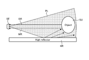
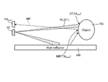
- FIGS. 1 and 2 are examples of errors in depth estimates due to indirect reflections from other objects.
- a highly reflective object HR such as a whiteboard exists around the subject SU.
- the ToF camera SE projects reference light PL toward the subject SU and receives its reflected light.
- the distance between the subject SU and the highly reflective object HR is short, a mixture of the direct reflected light DR that does not pass through the highly reflective object HR and the multipath light MR that passes through the highly reflective object HR enters the ToF camera SE.
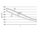
- the depth estimate DO is calculated as a larger value than the ground truth GT. In the example of FIG. 2, there is an error of about 100 mm.
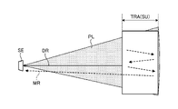
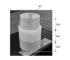
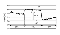
- FIGS. 3 to 5 are examples in which an error occurs in the estimated value of the depth due to scattering by the object SU.
- the subject SU includes an opaque object area OPA and a translucent object area TRA. Multiple reflections of the reference beam PL occur inside the translucent object area TRA. Multipath light MR generated by multiple reflection is detected by ToF camera SE together with direct reflected light DR. As a result, as shown in FIG. 5, the estimated value DO of the depth of the translucent object area TRA is calculated as a larger value than the ground truth GT. In the example of FIG. 5, there is an error of about 30 mm.
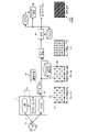
- FIG. 6 is a diagram showing a schematic configuration of the depth measuring system 1.
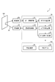
- FIG. 7 is a functional block diagram of the processing section 30. As shown in FIG.
- the measurement system 1 has a light projecting section 10 , a light receiving section 20 , a processing section 30 and a storage section 50 .
- the light projecting section 10 includes, for example, an actuator 11 and a light source 12 (see FIG. 15).
- Light source 12 is a laser or a projector that outputs reference light PL.
- the actuator 11 is a scanner that scans the subject SU with the reference light PL emitted from the light source 12 .
- the reference light PL is, for example, infrared light modulated with a sine wave.
- the light receiving section 20 is, for example, an image sensor having a plurality of pixels PX (see FIG. 14) arranged in the x and y directions. The z-direction orthogonal to the arrangement direction of the pixels PX is the depth direction. A light receiving element that detects the reference light PL is provided in the pixel PX. The light receiving unit 20 receives the reference light PL (reflected light RL) reflected by the subject SU.
- the light projecting unit 10 projects, as the reference light PL, a dot pattern PAT in which a plurality of dots DT are two-dimensionally arranged at regular intervals.
- the light projecting unit 10 scans the entire subject SU with the reference light PL at high density while shifting the projection position IP of the dot pattern PAT for each preset measurement period (one frame).
- the projection position IP is the measurement target position TA where depth measurement is performed using the directly reflected light DR.
- the light receiving unit 20 receives the reference light PL in accordance with the switching of the projection position IP.
- the light receiving unit 20 outputs the received light data for one measurement period to the processing unit 30 as frame data indicating the measurement result of the flight time of the reference light PL.
- the light receiving unit 20 continues to generate frame data until the scanning of the reference beam PL is completed, and sequentially outputs the generated frame data to the processing unit 30 .
- the frame data is time-series luminance data of each pixel PX measured in one measurement period.
- the frame data includes brightness data of the projection position IP and non-projection position NIP of the dot pattern PAT.
- the projection position IP is a position on the subject SU where the dot pattern PAT is directly projected.
- the non-projection position NIP is a position on the subject SU where the dot pattern PAT is not directly projected.
- the brightness data of the reference light PL at the projection position IP includes brightness data of both the direct reflected light DR and the multipath light MR.
- the brightness data of the reference light PL at the non-projection position NIP includes only the brightness data of the multipath light MR and does not include the brightness data of the directly reflected light DR.
- the processing unit 30 is an information processing device that processes various types of information.
- the processing unit 30 synchronously drives the light projecting unit 10 and the light receiving unit 20 and generates a depth map DM (see FIG. 8) based on the frame data acquired from the light receiving unit 20 .
- the processing unit 30 has a data acquisition unit 31 , depth estimation unit 32 , depth correction unit 33 , projection control unit 34 and discontinuation determination unit 35 .
- the projection control unit 34 controls the operations of the light source 12 and the actuator 11 based on the control plan CP (see FIG. 15).
- the control plan CP includes information such as the pattern shape of the reference beam PL, projection position IP and projection timing. Based on the control plan CP, the projection control unit 34 shifts the projection position IP of the dot pattern PAT for each measurement period while scanning the entire subject SU with the reference light PL at high density.
- the data acquisition unit 31 sequentially acquires frame data from the light receiving unit 20 every measurement period in accordance with the switching of the projection position IP.
- the depth estimation unit 32 sequentially generates a plurality of depth maps DM based on a plurality of frame data sequentially acquired from the data acquisition unit 31 .
- the depth estimation unit 32 extracts the luminance data of the reference light PL of each pixel PX from the frame data.
- the depth estimating unit 32 calculates the flight time of the reference light PL (the time from when the reference light PL is projected until it is reflected by the subject SU and received by the light receiving unit 20) from the arrival time delay obtained from the phase difference of the reflected light RL. time) is detected indirectly (iToF method).
- the depth estimation unit 32 estimates the depth of the subject SU for each pixel PX based on the flight time.
- the frame data includes luminance data of the reference light PL for the entire subject SU including the projection position IP and the non-projection position NIP.
- the depth estimation unit 32 estimates the depth of each pixel PX based on the frame data. Thereby, the depths of both the projection position IP where the reference light PL is projected and the non-projection position NIP shifted from the projection position IP are estimated.
- the depth correction unit 33 calculates the estimated value of the depth of the measurement target position TA obtained when the reference light PL is projected onto the measurement target position TA by combining the true value of the depth, the error component caused by the multipath light MR, Estimate a mixed depth value containing
- the depth correction unit 33 estimates the estimated value of the depth of the measurement target position TA obtained when the reference light PL is projected at a position shifted from the measurement target position TA as the error component.
- the depth correction unit 33 extracts, as error component information, depth value information estimated to be an error component from the plurality of depth maps DM sequentially generated by the depth estimation unit 32 .
- the depth correction unit 33 corrects the mixed depth value based on the error component by removing the error component from the mixed depth value.
- the depth correction unit 33 combines true value information extracted from a plurality of depth maps DM based on error component information to generate a combined depth map ADM. For example, the depth correction unit 33 corrects the latest depth map DM generated by the depth estimation unit 32 based on the error component information. The depth correction unit 33 synthesizes the latest corrected depth map DM with the latest synthesized depth map ADM. The most recent synthetic depth map ADM is a synthetic depth map ADM generated based on frame data of a plurality of measurement periods up to the last time. The depth correction unit 33 repeats correction and synthesis of the depth map DM every measurement period until the scanning of the reference light PL is completed. As a result, the density of the synthetic depth map ADM is gradually increased.
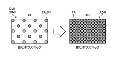
- FIG. 8 is a diagram showing the process of densifying the composite depth map ADM.
- the first depth map DM1 generated in the first measurement period is a sparse depth map DM corresponding to the dot pattern PAT.
- the measurement system 1 sequentially generates the depth map DM while shifting the projection position IP of the dot pattern PAT.
- the latest depth map DM is combined with the latest synthesized depth map ADM after being corrected based on the error component information.
- a new synthesized depth map ADM is generated by adding information on the depth of the latest measurement target position TA to the latest synthesized depth map ADM.
- depth information of the subject SU at q locations can be obtained by one measurement.
- a synthetic depth map ADM including information on the depth of the subject SU at q ⁇ Q locations is generated. Even if a sparse dot pattern PAT is used, repeated measurements generate a high-density synthetic depth map ADM in which depth information is accumulated.
- the projection control unit 34 sets a plurality of measurement target positions TA whose depth is to be measured on the subject SU.
- the projection control unit 34 divides the projection of the reference light PL onto all the measurement target positions TA into a plurality of times by shifting the projection position IP of the dot pattern PAT for each measurement period.
- the projection control unit 34 classifies all measurement target positions TA into a plurality of phase groups based on the projection timing of the reference light PL.
- the reference beam PL is projected at the same timing on a plurality of measurement target positions TA belonging to the same phase group.
- the projection control unit 34 sequentially projects the reference light PL for each phase group.
- a plurality of measurement target positions TA are classified into two phase groups of odd-numbered phases and even-numbered phases.
- a plurality of measurement target positions TA classified as odd phases are projection positions IP.
- a plurality of measurement target positions TA classified as even phases are non-projection positions NIP where the dot pattern PAT is not projected (directly).
- the even phase position TA even becomes the projected position IP and the odd phase position TA odd becomes the non-projected position NIP.
- the plurality of pixels PX of the light receiving unit 20 includes a plurality of odd phase pixels PX odd for measuring a plurality of odd phase positions TA odd and a plurality of pixels PX odd for measuring a plurality of even phase positions TA even .
- even phase pixels PX even even phase pixels PX even .
- Directly reflected light DR from the odd phase position TA odd enters the odd phase pixel PX odd when the odd phase position TA odd becomes the projection position IP.
- Directly reflected light DR from the even phase position TA even enters the even phase pixel PX even when the even phase position TA even becomes the projection position IP.
- a plurality of odd-numbered phase positions TA odd are projected positions IP. Therefore, as shown in FIG. 10, the odd-numbered phase pixel PX odd receives the direct reflected light DR reflected at the odd-numbered phase position TA odd , which is the projection position IP, and the multipath light MR reflected by the highly reflective object HR. Incident. On the other hand, as shown in FIG. 11, only the multipath light MR reflected by the highly reflective object HR is incident on the even phase pixel PX even . Since the projection position IP is not the even phase position TA even (the even phase position TA even is the non-projection position NIP), the direct reflected light DR reflected at the projection position IP does not enter the even phase pixels PX even .
- the multipath light MR which is an error component, is measured by both the odd phase pixels PX odd and the even phase pixels PX even .
- the directly reflected light DR indicating the true depth value is measured only by the odd-numbered phase pixels PX odd .
- the measurement system 1 estimates the depth of each measurement target position TA based on the relationship between the projection timing and the measurement data of each phase group.
- the projection control unit 34 projects the dot pattern PAT to a plurality of odd-numbered phase positions TA odd to perform the first measurement.
- the depth estimation unit 32 estimates the depth of each pixel PX based on the frame data obtained by the first measurement.
- the depth estimation unit 32 generates a first depth map DM1 based on the estimated value of the depth of each pixel PX.
- the depth correction unit 33 treats the depth value d even,k,l (k,l: x and y coordinates of the pixel) of each even-numbered phase pixel PX even (k,l) as an error component caused by the multipath light MR. presume.
- the depth correction unit 33 converts the depth value d odd,i,j (i, j: x and y coordinates of the pixel) of each odd-numbered phase pixel PX odd (i, j) into a mixed depth value including a true value and an error component. estimated as
- the projection control unit 34 projects the dot pattern PAT to a plurality of even-numbered phase positions TA even to perform the second measurement.
- the depth estimation unit 32 estimates the depth of each pixel PX based on the frame data obtained by the second measurement.
- the depth estimation unit 32 generates a second depth map DM2 based on the depth estimation value of each pixel PX.
- the depth correction unit 33 estimates the depth value d odd,i,j of each odd-numbered phase pixel PX odd (i,j) as an error component caused by the multipath light MR.
- the depth correction unit 33 estimates the depth value d even,k,l of each even-numbered phase pixel PX even (k,l) as a mixed depth value including a true value and an error component.
- the depth correction unit 33 extracts, as error component information, depth value information that is estimated to be an error component from the first depth map DM1 and the second depth map DM2.
- the depth correction unit 33 corrects the first depth map DM1 and the second depth map DM2 based on the error component information.
- the depth correction unit 33 from the depth value d odd,i,j of the odd-numbered phase pixel PX odd (i,j) included in the first depth map DM1, based on the following equation (1), the error component , the depth value d odd,i,j of the same odd-phase pixel PX odd (i,j) contained in the second depth map DM2.
- the depth correction unit 33 calculates the error component, the first Subtract the depth values d even,k,l of the same even-phase pixel PX even (k,l) included in one depth map DM1.
- the depth correction unit 33 synthesizes the corrected first depth map DM1 and the corrected second depth map DM2 to generate a high-density synthetic depth map ADM from which error components are removed.
- the number of phase groups (number of phases) is two, odd phases and even phases. However, the number of phases should be two or more, and may be three or more.
- the number of phases indicates the number of measurements required to scan all the measurement target positions TA. As the number of phases increases, the density of the depth map DM increases, but the measurement time increases. When the shape of the subject SU is simple, even if the density of the depth map DM is small, the shape of the subject SU may be accurately estimated by interpolation processing or the like. In such a case, the measurement can be terminated after a number of times less than the number of phases.
- the discontinuation determination unit 35 sequentially acquires the depth map DM generated for each measurement period from the depth correction unit 33 .
- the discontinuation determination unit 35 determines discontinuation of measurement based on transition of the estimated value of depth updated for each measurement period.
- the discontinuation determination unit 35 determines to discontinue the measurement when the transition of the estimated depth value satisfies a preset saturation condition.
- the termination determination section 35 outputs termination information to the projection control section 34 and the data acquisition section 31 .
- the projection control unit 34 and the data acquisition unit 31 stop projecting the reference beam PL and acquiring the received light data based on the discontinuation information.
- FIG. 13 is a diagram showing an example of termination determination.
- the discontinuation determination unit 35 extracts the geometry information GI of the subject SU from the depth map DM.
- the geometry information GI is calculated using the estimated value of the depth of the measurement target position TA that has already been measured.
- the discontinuation determination unit 35 updates the geometry information GI for each measurement period based on the latest measurement result.
- the discontinuation determination unit 35 detects changes in the geometry information GI before and after updating.
- the discontinuation determination unit 35 determines whether or not the transition of the estimated depth value satisfies the saturation condition based on the change in the geometry information GI. If the saturation condition is met, it is decided to truncate the measurement.
- the discontinuation determination unit 35 extracts, as the geometry information GI, information on the normal vector N of the subject SU at each measurement target position TA that has already been measured. If the change in the normal vector N before and after the update (magnitude of the difference in the normal vector) is equal to or less than a preset threshold at all the measurement target positions TA that have already been measured, the discontinuation determination unit 35 (
- ⁇ threshold), it is determined that the saturation condition is satisfied. Note that the symbol t indicates the number of measurements. "t n" means that the projection of the reference beam PL has been performed up to the nth phase group.
- the upper part of FIG. 13 shows an example in which the shape of the subject SU is a simple shape without irregular unevenness, such as a curved surface (scene A).
- scene A even if the number of measurements increases to n, (n+1), and (n+2), the orientation of the updated normal vector N does not change significantly.
- the discontinuation determination unit 35 determines discontinuation of the measurement with emphasis on efficiency of the measurement.
- the depth correction unit 33 interpolates the depth of the measurement target position TA for which measurement has not been completed, based on the estimated value of the depth of another measurement target position TA that has already been measured.
- the lower part of FIG. 13 shows an example in which the shape of the subject SU is a complex shape with unevenness such as steps (scene B).
- scene B the direction of the normal vector N changes greatly for each measurement.
- the discontinuation determination unit 35 determines that the shape of the subject SU cannot be accurately grasped only from the measured data, and determines to continue the measurement.
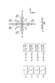
- FIG. 14 is a diagram showing an example of a method for calculating the normal vector N.
- the discontinuation determination unit 35 determines the normal vector N of the subject SU at the position i on the subject SU from the three-dimensional coordinates of the position i and the positions j 0 , j 1 , j 2 , and j 3 adjacent to the position i. Calculated using dimensional coordinates.
- the three -dimensional coordinates of the positions i , j0 , j1 , j2 , and j3 are the xy coordinates of the pixels PXi , PXj0 , PXj1, PXj2, and PXj3 corresponding to each position, and the pixels PXi , Using depth estimates D(i), D(j 0 ), D(j 1 ), D(j 2 ), D(j 3 ) detected at PX j0 , PX j1 , PX j2 , PX j3 Calculated.
- the discontinuation determination unit 35 calculates four vectors S 0 , S 1 , S 2 , S 3 directed from the positions j 0 , j 1 , j 2 , j 3 to the position i.
- the discontinuation determining unit 35 divides the rectangular area surrounded by the positions j 0 , j 1 , j 2 , and j 3 into four triangular areas with the position i as the vertex.
- the discontinuation determining unit 35 calculates normal vectors N 10 , N 02 , N 23 and N 31 of each triangular region using the vectors S 0 , S 1 , S 2 and S 3 .
- the discontinuation determination unit 35 calculates the average vector of the normal vectors N 10 , N 02 , N 23 and N 31 of the four triangular regions as the normal vector N at the position i.
- the setting information 51 includes the above-described various conditions and information on criteria such as thresholds.
- the setting information 51 and the program 59 used for the above process are stored in the storage unit 50 .
- the program 59 is a program that causes a computer to execute information processing according to this embodiment.
- the processing section 30 performs various processes according to the program 59 stored in the storage section 50 .
- the storage unit 50 may be used as a work area (buffer) that temporarily stores the processing results of the processing unit 30 .
- Storage unit 50 includes, for example, any non-transitory storage medium such as a semiconductor storage medium and a magnetic storage medium.
- the storage unit 50 includes, for example, an optical disc, a magneto-optical disc, or a flash memory.
- the program 59 is stored, for example, in a non-transitory computer-readable storage medium.
- the processing unit 30 is, for example, a computer configured with a processor and memory.
- the memory of the processing unit 30 includes RAM (Random Access Memory) and ROM (Read Only Memory).
- the processing unit 30 functions as a data acquisition unit 31 , a depth estimation unit 32 , a depth correction unit 33 , a projection control unit 34 and an end determination unit 35 by executing the program 59 .
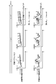
- Information processing method 15 and 16 are diagrams illustrating an example of information processing related to depth estimation.
- step S1 the projection control unit 34 sets the phase group number (group number) n to 1.
- step S2 the projection control section 34 determines whether or not the group number n is smaller than the number of phases. If it is determined in step S2 that the group number n is the same as the number of phases (step S2: No), the process ends. If it is determined in step S2 that the group number n is smaller than the number of phases (step S2: No), the process proceeds to step S3.
- step S3 the projection control unit 34 controls the light projecting unit 10 so that the plurality of measurement target positions TA corresponding to the group number n become the projection positions IP.
- step S4 the light projecting unit 10 projects the reference light PL onto a plurality of measurement target positions TA corresponding to the group number n at the timing controlled by the projection control unit 34.
- the light receiving unit 20 receives the reference light PL reflected by the subject SU, and outputs luminance data of the reference light PL measured at each pixel PX as frame data.
- the depth estimation unit 32 generates a depth map DM (first depth map DM1) based on the frame data.
- step S5 the projection control unit 34 controls the light projecting unit 10 so that the plurality of measurement target positions TA corresponding to the next group number n become the projection positions IP.
- all the measurement target positions TA are divided into odd-numbered phases and even-numbered phases. Therefore, the projection position IP for the second time is in phase opposite to the projection position IP for the first time.
- step S6 the light projecting unit 10 projects the reference light PL onto a plurality of measurement target positions TA corresponding to the next group number n at the timing controlled by the projection control unit 34.
- the light receiving unit 20 receives the reference light PL reflected by the subject SU, and outputs luminance data of the reference light PL measured at each pixel PX as frame data.
- the depth estimation unit 32 generates a depth map DM (second depth map DM2) based on the frame data.
- step S7 the depth correction unit 33 extracts error component information from the first depth map DM1 and the second depth map DM2.
- the depth correction unit 33 corrects the first depth map DM1 and the second depth map DM2 based on the error component information.
- step S8 the depth correction unit 33 combines the corrected first depth map DM1 and the corrected second depth map DM2 to generate a combined depth map ADM.
- the measurement target position TA is classified into two phase groups, so the measurement is completed twice.
- discontinuation determination is performed in step S9.
- the discontinuation determination unit 35 extracts the geometry information GI of the subject SU from both the corrected first depth map DM1 and the combined depth map ADM.
- the discontinuation determination unit 35 applies changes in the geometry information GI updated every measurement period based on the latest measurement result to the saturation condition. Based on, it is determined whether or not to terminate the measurement.
- step S10 the discontinuation determination unit 35 determines whether or not to discontinue measurement based on changes in the geometry information GI.
- the processing section 30 ends the processing. Due to the discontinuation of measurement, the depth of the measurement target position TA for which the measurement has not been completed is interpolated based on the estimated values of the depths of the other measurement target positions TA that have already been measured.
- step S10 if it is determined to continue the measurement (step S10: No), the process proceeds to step S11.
- step S11 the processing unit 30 advances the group number n by one, and repeats the above-described processing until termination is determined.
- the processing unit 30 has a depth estimation unit 32 and a depth correction unit 33 .
- the depth estimator 32 estimates the depth of the projection position IP where the reference light PL is projected and the depth of the non-projection position NIP shifted from the projection position IP, based on the measurement result of the flight time of the reference light PL.
- the depth correction unit 33 extracts, as an error component, an estimated value of the depth of the measurement target position TA obtained when the reference light PL is projected at a position shifted from the measurement target position TA of the subject SU.
- the depth correction unit 33 removes the error component from the estimated value of the depth of the measurement target position TA obtained when the reference light PL is projected onto the measurement target position TA.
- the processing of the processing unit 30 described above is executed by a computer.
- the program of the present embodiment causes a computer to implement the processing of the processing unit 30 described above.
- the processing unit 30 has a projection control unit 34.
- the projection control unit 34 scans the subject SU with the reference light PL while shifting the projection position IP of the reference light PL for each measurement period.
- the subject SU can be scanned with the reference light PL at high density.
- the projection control unit 34 projects the reference light PL as a dot pattern PAT in which a plurality of dots DT are two-dimensionally arranged.
- the depth measurement of a plurality of measurement target positions TA is performed at once.
- the depth estimation unit 32 generates a plurality of depth maps DM based on a plurality of received light data of the reference light PL acquired for each measurement period in accordance with the switching of the projection position IP.
- the depth correction unit 33 extracts, as error component information, information on depth values estimated as error components from the plurality of depth maps DM.
- the depth correction unit 33 extracts true value information from the plurality of depth maps DM based on the error component information.
- the depth correction unit 33 combines the extracted true value information to generate a combined depth map ADM.
- the processing unit 30 has an discontinuation determination unit 35 .
- the discontinuation determination unit 35 extracts the geometry information GI of the subject SU from the synthetic depth map ADM.
- the discontinuation determination unit 35 determines whether or not to discontinue measurement based on changes in the geometry information GI updated every measurement period based on the latest measurement results.
- the depth correction unit 33 interpolates the depth of the measurement target position TA for which measurement has not been completed due to the discontinuation of measurement, based on the estimated value of the depth of another measurement target position TA that has already been measured.
- the density of depth information does not decrease even if measurement is discontinued.
- the present technology can also take the following configuration.
- a depth estimating unit that estimates the depth of a projection position where the reference light is projected and a non-projection position shifted from the projection position based on the measurement result of the time of flight of the reference light;
- an estimated value of the depth of the measurement target position obtained when the reference light is projected to the measurement target position of the subject is extracted as an error component, and the reference light is projected onto the measurement target position.
- a depth correction unit that removes the error component from the estimated value of the depth of the measurement target position obtained in Information processing device having (2) a projection control unit that scans the subject with the reference light while shifting the projection position of the reference light for each measurement period; The information processing apparatus according to (1) above. (3) The projection control unit projects the reference light as a dot pattern in which a plurality of dots are arranged two-dimensionally. The information processing apparatus according to (2) above.
- the depth estimating unit generates a plurality of depth maps based on a plurality of received light data of the reference light acquired for each measurement period in accordance with the switching of the projection position,
- the depth correction unit extracts information of the depth value estimated as the error component from the plurality of depth maps as error component information, and extracts a true value extracted from the plurality of depth maps based on the error component information.
- generate a synthetic depth map by synthesizing information from The information processing apparatus according to (2) or (3) above.
- a discontinuation determination unit that extracts geometry information of the subject from the synthetic depth map and determines whether or not to discontinue measurement based on changes in the geometry information that is updated every measurement period based on the latest measurement results. having The information processing apparatus according to (4) above.
- the depth correction unit interpolates the depth of the measurement target position for which measurement has not been completed due to discontinuation of measurement, based on an estimated value of the depth of the other measurement target position that has already been measured.
- the information processing apparatus according to (5) above.
- (7) estimating the depth of a projection position where the reference light is projected and a non-projection position shifted from the projection position based on the measurement result of the flight time of the reference light; extracting, as an error component, an estimated value of the depth of the measurement target position obtained when the reference light is projected at a position shifted from the measurement target position of the object; removing the error component from an estimated value of the depth of the measurement target position obtained when the reference light is projected onto the measurement target position;
- a computer-implemented information processing method comprising: (8) estimating the depth of a projection position where the reference light is projected and a non-projection position shifted from the projection position based on the measurement result of the flight time of the reference light; extracting, as an error component, an estimated value of the depth
- processing unit (information processing device) 32 Depth estimation unit 33 Depth correction unit 34 Projection control unit 35 Abort determination unit 59 Program ADM Combined depth map DM Depth map DT Dot GI Geometry information IP Projection position NIP Non-projection position PAT Dot pattern PL Reference light SU Subject TA Measurement target position
Landscapes
- Physics & Mathematics (AREA)
- Engineering & Computer Science (AREA)
- General Physics & Mathematics (AREA)
- Computer Networks & Wireless Communication (AREA)
- Electromagnetism (AREA)
- Radar, Positioning & Navigation (AREA)
- Remote Sensing (AREA)
- Length Measuring Devices By Optical Means (AREA)
Abstract
La présente invention concerne un dispositif de traitement d'informations (30) comprenant une unité d'estimation de profondeur (32) et une unité de correction de profondeur (33). L'unité d'estimation de profondeur (32) estime, sur la base du résultat de la mesure de temps de vol d'une lumière de référence (PL), la profondeur d'une position de projection où la lumière de référence (PL) est projetée et une position de non-projection qui est décalée par rapport à la position de projection. L'unité de correction de profondeur (33) extrait, en tant que composante d'erreur, la valeur estimée de la profondeur d'une position à mesurer qui est obtenue lorsque la lumière de référence (PL) est projetée sur une position décalée par rapport à la position à mesurer d'un sujet (SU). L'unité de correction de profondeur (33) élimine la composante d'erreur de la valeur estimée de la profondeur de la position à mesurer qui est obtenue lorsque la lumière de référence (PL) est projetée sur la position à mesurer.
Applications Claiming Priority (2)
| Application Number | Priority Date | Filing Date | Title |
|---|---|---|---|
| JP2021047238 | 2021-03-22 | ||
| JP2021-047238 | 2021-03-22 |
Publications (1)
| Publication Number | Publication Date |
|---|---|
| WO2022201848A1 true WO2022201848A1 (fr) | 2022-09-29 |
Family
ID=83395407
Family Applications (1)
| Application Number | Title | Priority Date | Filing Date |
|---|---|---|---|
| PCT/JP2022/003234 Ceased WO2022201848A1 (fr) | 2021-03-22 | 2022-01-28 | Dispositif de traitement d'informations, procédé de traitement d'informations et programme |
Country Status (1)
| Country | Link |
|---|---|
| WO (1) | WO2022201848A1 (fr) |
Citations (4)
| Publication number | Priority date | Publication date | Assignee | Title |
|---|---|---|---|---|
| WO2006118286A1 (fr) * | 2005-05-02 | 2006-11-09 | Matsushita Electric Works, Ltd. | Dispositif de detection d’informations concernant l’espace, et systeme de detection d’informations concernant l’espace utilisant le dispositif |
| US20130148102A1 (en) * | 2011-12-12 | 2013-06-13 | Mesa Imaging Ag | Method to Compensate for Errors in Time-of-Flight Range Cameras Caused by Multiple Reflections |
| JP2019529924A (ja) * | 2016-09-30 | 2019-10-17 | マジック リープ, インコーポレイテッドMagic Leap,Inc. | 空間光変調を伴うプロジェクタ |
| JP2021039131A (ja) * | 2014-06-11 | 2021-03-11 | ソニー デプスセンシング ソリューションズ エスエー エヌブイ | Tofカメラシステムおよび該システムにより距離を測定するための方法 |
-
2022
- 2022-01-28 WO PCT/JP2022/003234 patent/WO2022201848A1/fr not_active Ceased
Patent Citations (4)
| Publication number | Priority date | Publication date | Assignee | Title |
|---|---|---|---|---|
| WO2006118286A1 (fr) * | 2005-05-02 | 2006-11-09 | Matsushita Electric Works, Ltd. | Dispositif de detection d’informations concernant l’espace, et systeme de detection d’informations concernant l’espace utilisant le dispositif |
| US20130148102A1 (en) * | 2011-12-12 | 2013-06-13 | Mesa Imaging Ag | Method to Compensate for Errors in Time-of-Flight Range Cameras Caused by Multiple Reflections |
| JP2021039131A (ja) * | 2014-06-11 | 2021-03-11 | ソニー デプスセンシング ソリューションズ エスエー エヌブイ | Tofカメラシステムおよび該システムにより距離を測定するための方法 |
| JP2019529924A (ja) * | 2016-09-30 | 2019-10-17 | マジック リープ, インコーポレイテッドMagic Leap,Inc. | 空間光変調を伴うプロジェクタ |
Similar Documents
| Publication | Publication Date | Title |
|---|---|---|
| JP5632762B2 (ja) | 測位情報形成装置、検出装置、及び測位情報形成方法 | |
| EP2538242B1 (fr) | Amélioration de la qualité de mesure de profondeur | |
| JP5132832B1 (ja) | 計測装置および情報処理装置 | |
| US9786062B2 (en) | Scene reconstruction from high spatio-angular resolution light fields | |
| US20110285910A1 (en) | Video manipulation of red, green, blue, distance (RGB-Z) data including segmentation, up-sampling, and background substitution techniques | |
| EP2722646A1 (fr) | Dispositif de mesure de distance et appareil de génération de carte d'environnement | |
| CN106997582A (zh) | 飞行时间三维传感器的运动模糊消除方法和设备 | |
| EP3832601B1 (fr) | Dispositif de traitement d'image et système de mesure tridimensionnelle | |
| WO2012120856A1 (fr) | Dispositif et procédé de détection d'objets | |
| US9280846B2 (en) | Method, apparatus, and computer-readable recording medium for depth warping based occlusion culling | |
| KR20120068470A (ko) | 스테레오 영상 정합 장치 및 그 방법 | |
| WO2015057098A1 (fr) | Procédé et appareil de compensation de mouvement pour images de profondeur | |
| JP2005037378A (ja) | 奥行計測方法と奥行計測装置 | |
| CN110189265B (zh) | 距离能量相关三维成像超级像素修复方法 | |
| JPWO2022239573A5 (fr) | ||
| JP4394487B2 (ja) | ステレオ画像処理装置 | |
| JP2001194126A (ja) | 三次元形状計測装置および三次元形状計測方法、並びにプログラム提供媒体 | |
| KR20090068943A (ko) | 변이 추정 시의 비용 함수 연산 방법 및 가려진 영역 처리방법 | |
| KR102543027B1 (ko) | 3차원 이미지를 획득하기 위한 방법 및 장치 | |
| WO2022201848A1 (fr) | Dispositif de traitement d'informations, procédé de traitement d'informations et programme | |
| JP2004508641A (ja) | ディジタル画像のセグメンテーション | |
| US8897547B2 (en) | Precision improving device for three dimensional topographical data, precision improving method for three dimensional topographical data and recording medium | |
| JP2001324313A (ja) | 三次元形状計測装置 | |
| Fong et al. | High-resolution three-dimensional sensing of fast deforming objects | |
| JP6867766B2 (ja) | 情報処理装置およびその制御方法、プログラム |
Legal Events
| Date | Code | Title | Description |
|---|---|---|---|
| 121 | Ep: the epo has been informed by wipo that ep was designated in this application |
Ref document number: 22774650 Country of ref document: EP Kind code of ref document: A1 |
|
| NENP | Non-entry into the national phase |
Ref country code: DE |
|
| 122 | Ep: pct application non-entry in european phase |
Ref document number: 22774650 Country of ref document: EP Kind code of ref document: A1 |
|
| NENP | Non-entry into the national phase |
Ref country code: JP |