WO2022201848A1 - Information processing device, information processing method, and program - Google Patents
Information processing device, information processing method, and program Download PDFInfo
- Publication number
- WO2022201848A1 WO2022201848A1 PCT/JP2022/003234 JP2022003234W WO2022201848A1 WO 2022201848 A1 WO2022201848 A1 WO 2022201848A1 JP 2022003234 W JP2022003234 W JP 2022003234W WO 2022201848 A1 WO2022201848 A1 WO 2022201848A1
- Authority
- WO
- WIPO (PCT)
- Prior art keywords
- depth
- reference light
- measurement
- measurement target
- target position
- Prior art date
- Legal status (The legal status is an assumption and is not a legal conclusion. Google has not performed a legal analysis and makes no representation as to the accuracy of the status listed.)
- Ceased
Links
Images


Classifications
-
- G—PHYSICS
- G01—MEASURING; TESTING
- G01B—MEASURING LENGTH, THICKNESS OR SIMILAR LINEAR DIMENSIONS; MEASURING ANGLES; MEASURING AREAS; MEASURING IRREGULARITIES OF SURFACES OR CONTOURS
- G01B11/00—Measuring arrangements characterised by the use of optical techniques
- G01B11/24—Measuring arrangements characterised by the use of optical techniques for measuring contours or curvatures
-
- G—PHYSICS
- G01—MEASURING; TESTING
- G01S—RADIO DIRECTION-FINDING; RADIO NAVIGATION; DETERMINING DISTANCE OR VELOCITY BY USE OF RADIO WAVES; LOCATING OR PRESENCE-DETECTING BY USE OF THE REFLECTION OR RERADIATION OF RADIO WAVES; ANALOGOUS ARRANGEMENTS USING OTHER WAVES
- G01S17/00—Systems using the reflection or reradiation of electromagnetic waves other than radio waves, e.g. lidar systems
- G01S17/88—Lidar systems specially adapted for specific applications
- G01S17/89—Lidar systems specially adapted for specific applications for mapping or imaging
Definitions
- the present invention relates to an information processing device, an information processing method, and a program.
- Three-dimensional measurement technology using the ToF (Time of Flight) method is known.
- the depth of the object is detected based on information on the time from when the reference light is projected toward the object until the reflected light is received.
- the ToF method includes the dToF (direct Time of Flight) method and the iToF (indirect Time of Flight) method.
- dToF direct Time of Flight
- iToF indirect Time of Flight
- this disclosure proposes a depth measurement method that can reduce errors due to multipath interference.
- a depth estimating unit that estimates the depth of a projection position where the reference light is projected and a non-projection position shifted from the projection position based on a measurement result of the time of flight of the reference light; is projected to a position deviated from the measurement target position of the subject, extracting an estimated value of the depth of the measurement target position as an error component, and obtaining when the reference light is projected to the measurement target position and a depth correction unit that removes the error component from the estimated value of the depth of the measurement target position.
- FIG. 1 is a diagram showing a schematic configuration of a depth measurement system
- FIG. 4 is a functional block diagram of a processing unit
- FIG. 10 is a diagram showing a process in which a synthetic depth map is densified
- FIG. 4 is a diagram showing an example of a method of calculating a normal vector N
- FIG. 5 is a diagram showing an example of information processing related to depth estimation
- FIG. 5 is a diagram showing an example of information processing related to depth estimation
- the received light waveform of the reference light PL includes not only direct reflection components from the subject SU, but also multipath components caused by scattering within the subject SU and indirect reflection from other objects. If the depth is calculated based on received light data containing multipath components, an error occurs in the estimated value of the depth. This problem is known as the multipath problem.
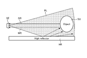
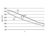
- FIGS. 1 and 2 are examples of errors in depth estimates due to indirect reflections from other objects.
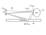
- a highly reflective object HR such as a whiteboard exists around the subject SU.
- the ToF camera SE projects reference light PL toward the subject SU and receives its reflected light.
- the distance between the subject SU and the highly reflective object HR is short, a mixture of the direct reflected light DR that does not pass through the highly reflective object HR and the multipath light MR that passes through the highly reflective object HR enters the ToF camera SE.
- the depth estimate DO is calculated as a larger value than the ground truth GT. In the example of FIG. 2, there is an error of about 100 mm.
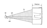
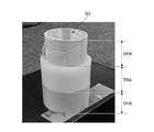
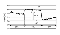
- FIGS. 3 to 5 are examples in which an error occurs in the estimated value of the depth due to scattering by the object SU.
- the subject SU includes an opaque object area OPA and a translucent object area TRA. Multiple reflections of the reference beam PL occur inside the translucent object area TRA. Multipath light MR generated by multiple reflection is detected by ToF camera SE together with direct reflected light DR. As a result, as shown in FIG. 5, the estimated value DO of the depth of the translucent object area TRA is calculated as a larger value than the ground truth GT. In the example of FIG. 5, there is an error of about 30 mm.
- FIG. 6 is a diagram showing a schematic configuration of the depth measuring system 1.
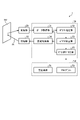
- FIG. 7 is a functional block diagram of the processing section 30. As shown in FIG.
- the measurement system 1 has a light projecting section 10 , a light receiving section 20 , a processing section 30 and a storage section 50 .
- the light projecting section 10 includes, for example, an actuator 11 and a light source 12 (see FIG. 15).
- Light source 12 is a laser or a projector that outputs reference light PL.
- the actuator 11 is a scanner that scans the subject SU with the reference light PL emitted from the light source 12 .
- the reference light PL is, for example, infrared light modulated with a sine wave.
- the light receiving section 20 is, for example, an image sensor having a plurality of pixels PX (see FIG. 14) arranged in the x and y directions. The z-direction orthogonal to the arrangement direction of the pixels PX is the depth direction. A light receiving element that detects the reference light PL is provided in the pixel PX. The light receiving unit 20 receives the reference light PL (reflected light RL) reflected by the subject SU.
- the light projecting unit 10 projects, as the reference light PL, a dot pattern PAT in which a plurality of dots DT are two-dimensionally arranged at regular intervals.
- the light projecting unit 10 scans the entire subject SU with the reference light PL at high density while shifting the projection position IP of the dot pattern PAT for each preset measurement period (one frame).
- the projection position IP is the measurement target position TA where depth measurement is performed using the directly reflected light DR.
- the light receiving unit 20 receives the reference light PL in accordance with the switching of the projection position IP.
- the light receiving unit 20 outputs the received light data for one measurement period to the processing unit 30 as frame data indicating the measurement result of the flight time of the reference light PL.
- the light receiving unit 20 continues to generate frame data until the scanning of the reference beam PL is completed, and sequentially outputs the generated frame data to the processing unit 30 .
- the frame data is time-series luminance data of each pixel PX measured in one measurement period.
- the frame data includes brightness data of the projection position IP and non-projection position NIP of the dot pattern PAT.
- the projection position IP is a position on the subject SU where the dot pattern PAT is directly projected.
- the non-projection position NIP is a position on the subject SU where the dot pattern PAT is not directly projected.
- the brightness data of the reference light PL at the projection position IP includes brightness data of both the direct reflected light DR and the multipath light MR.
- the brightness data of the reference light PL at the non-projection position NIP includes only the brightness data of the multipath light MR and does not include the brightness data of the directly reflected light DR.
- the processing unit 30 is an information processing device that processes various types of information.
- the processing unit 30 synchronously drives the light projecting unit 10 and the light receiving unit 20 and generates a depth map DM (see FIG. 8) based on the frame data acquired from the light receiving unit 20 .
- the processing unit 30 has a data acquisition unit 31 , depth estimation unit 32 , depth correction unit 33 , projection control unit 34 and discontinuation determination unit 35 .
- the projection control unit 34 controls the operations of the light source 12 and the actuator 11 based on the control plan CP (see FIG. 15).
- the control plan CP includes information such as the pattern shape of the reference beam PL, projection position IP and projection timing. Based on the control plan CP, the projection control unit 34 shifts the projection position IP of the dot pattern PAT for each measurement period while scanning the entire subject SU with the reference light PL at high density.
- the data acquisition unit 31 sequentially acquires frame data from the light receiving unit 20 every measurement period in accordance with the switching of the projection position IP.
- the depth estimation unit 32 sequentially generates a plurality of depth maps DM based on a plurality of frame data sequentially acquired from the data acquisition unit 31 .
- the depth estimation unit 32 extracts the luminance data of the reference light PL of each pixel PX from the frame data.
- the depth estimating unit 32 calculates the flight time of the reference light PL (the time from when the reference light PL is projected until it is reflected by the subject SU and received by the light receiving unit 20) from the arrival time delay obtained from the phase difference of the reflected light RL. time) is detected indirectly (iToF method).
- the depth estimation unit 32 estimates the depth of the subject SU for each pixel PX based on the flight time.
- the frame data includes luminance data of the reference light PL for the entire subject SU including the projection position IP and the non-projection position NIP.
- the depth estimation unit 32 estimates the depth of each pixel PX based on the frame data. Thereby, the depths of both the projection position IP where the reference light PL is projected and the non-projection position NIP shifted from the projection position IP are estimated.
- the depth correction unit 33 calculates the estimated value of the depth of the measurement target position TA obtained when the reference light PL is projected onto the measurement target position TA by combining the true value of the depth, the error component caused by the multipath light MR, Estimate a mixed depth value containing
- the depth correction unit 33 estimates the estimated value of the depth of the measurement target position TA obtained when the reference light PL is projected at a position shifted from the measurement target position TA as the error component.
- the depth correction unit 33 extracts, as error component information, depth value information estimated to be an error component from the plurality of depth maps DM sequentially generated by the depth estimation unit 32 .
- the depth correction unit 33 corrects the mixed depth value based on the error component by removing the error component from the mixed depth value.
- the depth correction unit 33 combines true value information extracted from a plurality of depth maps DM based on error component information to generate a combined depth map ADM. For example, the depth correction unit 33 corrects the latest depth map DM generated by the depth estimation unit 32 based on the error component information. The depth correction unit 33 synthesizes the latest corrected depth map DM with the latest synthesized depth map ADM. The most recent synthetic depth map ADM is a synthetic depth map ADM generated based on frame data of a plurality of measurement periods up to the last time. The depth correction unit 33 repeats correction and synthesis of the depth map DM every measurement period until the scanning of the reference light PL is completed. As a result, the density of the synthetic depth map ADM is gradually increased.
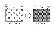
- FIG. 8 is a diagram showing the process of densifying the composite depth map ADM.
- the first depth map DM1 generated in the first measurement period is a sparse depth map DM corresponding to the dot pattern PAT.
- the measurement system 1 sequentially generates the depth map DM while shifting the projection position IP of the dot pattern PAT.
- the latest depth map DM is combined with the latest synthesized depth map ADM after being corrected based on the error component information.
- a new synthesized depth map ADM is generated by adding information on the depth of the latest measurement target position TA to the latest synthesized depth map ADM.
- depth information of the subject SU at q locations can be obtained by one measurement.
- a synthetic depth map ADM including information on the depth of the subject SU at q ⁇ Q locations is generated. Even if a sparse dot pattern PAT is used, repeated measurements generate a high-density synthetic depth map ADM in which depth information is accumulated.
- the projection control unit 34 sets a plurality of measurement target positions TA whose depth is to be measured on the subject SU.
- the projection control unit 34 divides the projection of the reference light PL onto all the measurement target positions TA into a plurality of times by shifting the projection position IP of the dot pattern PAT for each measurement period.
- the projection control unit 34 classifies all measurement target positions TA into a plurality of phase groups based on the projection timing of the reference light PL.
- the reference beam PL is projected at the same timing on a plurality of measurement target positions TA belonging to the same phase group.
- the projection control unit 34 sequentially projects the reference light PL for each phase group.
- a plurality of measurement target positions TA are classified into two phase groups of odd-numbered phases and even-numbered phases.
- a plurality of measurement target positions TA classified as odd phases are projection positions IP.
- a plurality of measurement target positions TA classified as even phases are non-projection positions NIP where the dot pattern PAT is not projected (directly).
- the even phase position TA even becomes the projected position IP and the odd phase position TA odd becomes the non-projected position NIP.
- the plurality of pixels PX of the light receiving unit 20 includes a plurality of odd phase pixels PX odd for measuring a plurality of odd phase positions TA odd and a plurality of pixels PX odd for measuring a plurality of even phase positions TA even .
- even phase pixels PX even even phase pixels PX even .
- Directly reflected light DR from the odd phase position TA odd enters the odd phase pixel PX odd when the odd phase position TA odd becomes the projection position IP.
- Directly reflected light DR from the even phase position TA even enters the even phase pixel PX even when the even phase position TA even becomes the projection position IP.
- a plurality of odd-numbered phase positions TA odd are projected positions IP. Therefore, as shown in FIG. 10, the odd-numbered phase pixel PX odd receives the direct reflected light DR reflected at the odd-numbered phase position TA odd , which is the projection position IP, and the multipath light MR reflected by the highly reflective object HR. Incident. On the other hand, as shown in FIG. 11, only the multipath light MR reflected by the highly reflective object HR is incident on the even phase pixel PX even . Since the projection position IP is not the even phase position TA even (the even phase position TA even is the non-projection position NIP), the direct reflected light DR reflected at the projection position IP does not enter the even phase pixels PX even .
- the multipath light MR which is an error component, is measured by both the odd phase pixels PX odd and the even phase pixels PX even .
- the directly reflected light DR indicating the true depth value is measured only by the odd-numbered phase pixels PX odd .
- the measurement system 1 estimates the depth of each measurement target position TA based on the relationship between the projection timing and the measurement data of each phase group.
- the projection control unit 34 projects the dot pattern PAT to a plurality of odd-numbered phase positions TA odd to perform the first measurement.
- the depth estimation unit 32 estimates the depth of each pixel PX based on the frame data obtained by the first measurement.
- the depth estimation unit 32 generates a first depth map DM1 based on the estimated value of the depth of each pixel PX.
- the depth correction unit 33 treats the depth value d even,k,l (k,l: x and y coordinates of the pixel) of each even-numbered phase pixel PX even (k,l) as an error component caused by the multipath light MR. presume.
- the depth correction unit 33 converts the depth value d odd,i,j (i, j: x and y coordinates of the pixel) of each odd-numbered phase pixel PX odd (i, j) into a mixed depth value including a true value and an error component. estimated as
- the projection control unit 34 projects the dot pattern PAT to a plurality of even-numbered phase positions TA even to perform the second measurement.
- the depth estimation unit 32 estimates the depth of each pixel PX based on the frame data obtained by the second measurement.
- the depth estimation unit 32 generates a second depth map DM2 based on the depth estimation value of each pixel PX.
- the depth correction unit 33 estimates the depth value d odd,i,j of each odd-numbered phase pixel PX odd (i,j) as an error component caused by the multipath light MR.
- the depth correction unit 33 estimates the depth value d even,k,l of each even-numbered phase pixel PX even (k,l) as a mixed depth value including a true value and an error component.
- the depth correction unit 33 extracts, as error component information, depth value information that is estimated to be an error component from the first depth map DM1 and the second depth map DM2.
- the depth correction unit 33 corrects the first depth map DM1 and the second depth map DM2 based on the error component information.
- the depth correction unit 33 from the depth value d odd,i,j of the odd-numbered phase pixel PX odd (i,j) included in the first depth map DM1, based on the following equation (1), the error component , the depth value d odd,i,j of the same odd-phase pixel PX odd (i,j) contained in the second depth map DM2.
- the depth correction unit 33 calculates the error component, the first Subtract the depth values d even,k,l of the same even-phase pixel PX even (k,l) included in one depth map DM1.
- the depth correction unit 33 synthesizes the corrected first depth map DM1 and the corrected second depth map DM2 to generate a high-density synthetic depth map ADM from which error components are removed.
- the number of phase groups (number of phases) is two, odd phases and even phases. However, the number of phases should be two or more, and may be three or more.
- the number of phases indicates the number of measurements required to scan all the measurement target positions TA. As the number of phases increases, the density of the depth map DM increases, but the measurement time increases. When the shape of the subject SU is simple, even if the density of the depth map DM is small, the shape of the subject SU may be accurately estimated by interpolation processing or the like. In such a case, the measurement can be terminated after a number of times less than the number of phases.
- the discontinuation determination unit 35 sequentially acquires the depth map DM generated for each measurement period from the depth correction unit 33 .
- the discontinuation determination unit 35 determines discontinuation of measurement based on transition of the estimated value of depth updated for each measurement period.
- the discontinuation determination unit 35 determines to discontinue the measurement when the transition of the estimated depth value satisfies a preset saturation condition.
- the termination determination section 35 outputs termination information to the projection control section 34 and the data acquisition section 31 .
- the projection control unit 34 and the data acquisition unit 31 stop projecting the reference beam PL and acquiring the received light data based on the discontinuation information.
- FIG. 13 is a diagram showing an example of termination determination.
- the discontinuation determination unit 35 extracts the geometry information GI of the subject SU from the depth map DM.
- the geometry information GI is calculated using the estimated value of the depth of the measurement target position TA that has already been measured.
- the discontinuation determination unit 35 updates the geometry information GI for each measurement period based on the latest measurement result.
- the discontinuation determination unit 35 detects changes in the geometry information GI before and after updating.
- the discontinuation determination unit 35 determines whether or not the transition of the estimated depth value satisfies the saturation condition based on the change in the geometry information GI. If the saturation condition is met, it is decided to truncate the measurement.
- the discontinuation determination unit 35 extracts, as the geometry information GI, information on the normal vector N of the subject SU at each measurement target position TA that has already been measured. If the change in the normal vector N before and after the update (magnitude of the difference in the normal vector) is equal to or less than a preset threshold at all the measurement target positions TA that have already been measured, the discontinuation determination unit 35 (
- ⁇ threshold), it is determined that the saturation condition is satisfied. Note that the symbol t indicates the number of measurements. "t n" means that the projection of the reference beam PL has been performed up to the nth phase group.
- the upper part of FIG. 13 shows an example in which the shape of the subject SU is a simple shape without irregular unevenness, such as a curved surface (scene A).
- scene A even if the number of measurements increases to n, (n+1), and (n+2), the orientation of the updated normal vector N does not change significantly.
- the discontinuation determination unit 35 determines discontinuation of the measurement with emphasis on efficiency of the measurement.
- the depth correction unit 33 interpolates the depth of the measurement target position TA for which measurement has not been completed, based on the estimated value of the depth of another measurement target position TA that has already been measured.
- the lower part of FIG. 13 shows an example in which the shape of the subject SU is a complex shape with unevenness such as steps (scene B).
- scene B the direction of the normal vector N changes greatly for each measurement.
- the discontinuation determination unit 35 determines that the shape of the subject SU cannot be accurately grasped only from the measured data, and determines to continue the measurement.
- FIG. 14 is a diagram showing an example of a method for calculating the normal vector N.
- the discontinuation determination unit 35 determines the normal vector N of the subject SU at the position i on the subject SU from the three-dimensional coordinates of the position i and the positions j 0 , j 1 , j 2 , and j 3 adjacent to the position i. Calculated using dimensional coordinates.
- the three -dimensional coordinates of the positions i , j0 , j1 , j2 , and j3 are the xy coordinates of the pixels PXi , PXj0 , PXj1, PXj2, and PXj3 corresponding to each position, and the pixels PXi , Using depth estimates D(i), D(j 0 ), D(j 1 ), D(j 2 ), D(j 3 ) detected at PX j0 , PX j1 , PX j2 , PX j3 Calculated.
- the discontinuation determination unit 35 calculates four vectors S 0 , S 1 , S 2 , S 3 directed from the positions j 0 , j 1 , j 2 , j 3 to the position i.
- the discontinuation determining unit 35 divides the rectangular area surrounded by the positions j 0 , j 1 , j 2 , and j 3 into four triangular areas with the position i as the vertex.
- the discontinuation determining unit 35 calculates normal vectors N 10 , N 02 , N 23 and N 31 of each triangular region using the vectors S 0 , S 1 , S 2 and S 3 .
- the discontinuation determination unit 35 calculates the average vector of the normal vectors N 10 , N 02 , N 23 and N 31 of the four triangular regions as the normal vector N at the position i.
- the setting information 51 includes the above-described various conditions and information on criteria such as thresholds.
- the setting information 51 and the program 59 used for the above process are stored in the storage unit 50 .
- the program 59 is a program that causes a computer to execute information processing according to this embodiment.
- the processing section 30 performs various processes according to the program 59 stored in the storage section 50 .
- the storage unit 50 may be used as a work area (buffer) that temporarily stores the processing results of the processing unit 30 .
- Storage unit 50 includes, for example, any non-transitory storage medium such as a semiconductor storage medium and a magnetic storage medium.
- the storage unit 50 includes, for example, an optical disc, a magneto-optical disc, or a flash memory.
- the program 59 is stored, for example, in a non-transitory computer-readable storage medium.
- the processing unit 30 is, for example, a computer configured with a processor and memory.
- the memory of the processing unit 30 includes RAM (Random Access Memory) and ROM (Read Only Memory).
- the processing unit 30 functions as a data acquisition unit 31 , a depth estimation unit 32 , a depth correction unit 33 , a projection control unit 34 and an end determination unit 35 by executing the program 59 .
- Information processing method 15 and 16 are diagrams illustrating an example of information processing related to depth estimation.
- step S1 the projection control unit 34 sets the phase group number (group number) n to 1.
- step S2 the projection control section 34 determines whether or not the group number n is smaller than the number of phases. If it is determined in step S2 that the group number n is the same as the number of phases (step S2: No), the process ends. If it is determined in step S2 that the group number n is smaller than the number of phases (step S2: No), the process proceeds to step S3.
- step S3 the projection control unit 34 controls the light projecting unit 10 so that the plurality of measurement target positions TA corresponding to the group number n become the projection positions IP.
- step S4 the light projecting unit 10 projects the reference light PL onto a plurality of measurement target positions TA corresponding to the group number n at the timing controlled by the projection control unit 34.
- the light receiving unit 20 receives the reference light PL reflected by the subject SU, and outputs luminance data of the reference light PL measured at each pixel PX as frame data.
- the depth estimation unit 32 generates a depth map DM (first depth map DM1) based on the frame data.
- step S5 the projection control unit 34 controls the light projecting unit 10 so that the plurality of measurement target positions TA corresponding to the next group number n become the projection positions IP.
- all the measurement target positions TA are divided into odd-numbered phases and even-numbered phases. Therefore, the projection position IP for the second time is in phase opposite to the projection position IP for the first time.
- step S6 the light projecting unit 10 projects the reference light PL onto a plurality of measurement target positions TA corresponding to the next group number n at the timing controlled by the projection control unit 34.
- the light receiving unit 20 receives the reference light PL reflected by the subject SU, and outputs luminance data of the reference light PL measured at each pixel PX as frame data.
- the depth estimation unit 32 generates a depth map DM (second depth map DM2) based on the frame data.
- step S7 the depth correction unit 33 extracts error component information from the first depth map DM1 and the second depth map DM2.
- the depth correction unit 33 corrects the first depth map DM1 and the second depth map DM2 based on the error component information.
- step S8 the depth correction unit 33 combines the corrected first depth map DM1 and the corrected second depth map DM2 to generate a combined depth map ADM.
- the measurement target position TA is classified into two phase groups, so the measurement is completed twice.
- discontinuation determination is performed in step S9.
- the discontinuation determination unit 35 extracts the geometry information GI of the subject SU from both the corrected first depth map DM1 and the combined depth map ADM.
- the discontinuation determination unit 35 applies changes in the geometry information GI updated every measurement period based on the latest measurement result to the saturation condition. Based on, it is determined whether or not to terminate the measurement.
- step S10 the discontinuation determination unit 35 determines whether or not to discontinue measurement based on changes in the geometry information GI.
- the processing section 30 ends the processing. Due to the discontinuation of measurement, the depth of the measurement target position TA for which the measurement has not been completed is interpolated based on the estimated values of the depths of the other measurement target positions TA that have already been measured.
- step S10 if it is determined to continue the measurement (step S10: No), the process proceeds to step S11.
- step S11 the processing unit 30 advances the group number n by one, and repeats the above-described processing until termination is determined.
- the processing unit 30 has a depth estimation unit 32 and a depth correction unit 33 .
- the depth estimator 32 estimates the depth of the projection position IP where the reference light PL is projected and the depth of the non-projection position NIP shifted from the projection position IP, based on the measurement result of the flight time of the reference light PL.
- the depth correction unit 33 extracts, as an error component, an estimated value of the depth of the measurement target position TA obtained when the reference light PL is projected at a position shifted from the measurement target position TA of the subject SU.
- the depth correction unit 33 removes the error component from the estimated value of the depth of the measurement target position TA obtained when the reference light PL is projected onto the measurement target position TA.
- the processing of the processing unit 30 described above is executed by a computer.
- the program of the present embodiment causes a computer to implement the processing of the processing unit 30 described above.
- the processing unit 30 has a projection control unit 34.
- the projection control unit 34 scans the subject SU with the reference light PL while shifting the projection position IP of the reference light PL for each measurement period.
- the subject SU can be scanned with the reference light PL at high density.
- the projection control unit 34 projects the reference light PL as a dot pattern PAT in which a plurality of dots DT are two-dimensionally arranged.
- the depth measurement of a plurality of measurement target positions TA is performed at once.
- the depth estimation unit 32 generates a plurality of depth maps DM based on a plurality of received light data of the reference light PL acquired for each measurement period in accordance with the switching of the projection position IP.
- the depth correction unit 33 extracts, as error component information, information on depth values estimated as error components from the plurality of depth maps DM.
- the depth correction unit 33 extracts true value information from the plurality of depth maps DM based on the error component information.
- the depth correction unit 33 combines the extracted true value information to generate a combined depth map ADM.
- the processing unit 30 has an discontinuation determination unit 35 .
- the discontinuation determination unit 35 extracts the geometry information GI of the subject SU from the synthetic depth map ADM.
- the discontinuation determination unit 35 determines whether or not to discontinue measurement based on changes in the geometry information GI updated every measurement period based on the latest measurement results.
- the depth correction unit 33 interpolates the depth of the measurement target position TA for which measurement has not been completed due to the discontinuation of measurement, based on the estimated value of the depth of another measurement target position TA that has already been measured.
- the density of depth information does not decrease even if measurement is discontinued.
- the present technology can also take the following configuration.
- a depth estimating unit that estimates the depth of a projection position where the reference light is projected and a non-projection position shifted from the projection position based on the measurement result of the time of flight of the reference light;
- an estimated value of the depth of the measurement target position obtained when the reference light is projected to the measurement target position of the subject is extracted as an error component, and the reference light is projected onto the measurement target position.
- a depth correction unit that removes the error component from the estimated value of the depth of the measurement target position obtained in Information processing device having (2) a projection control unit that scans the subject with the reference light while shifting the projection position of the reference light for each measurement period; The information processing apparatus according to (1) above. (3) The projection control unit projects the reference light as a dot pattern in which a plurality of dots are arranged two-dimensionally. The information processing apparatus according to (2) above.
- the depth estimating unit generates a plurality of depth maps based on a plurality of received light data of the reference light acquired for each measurement period in accordance with the switching of the projection position,
- the depth correction unit extracts information of the depth value estimated as the error component from the plurality of depth maps as error component information, and extracts a true value extracted from the plurality of depth maps based on the error component information.
- generate a synthetic depth map by synthesizing information from The information processing apparatus according to (2) or (3) above.
- a discontinuation determination unit that extracts geometry information of the subject from the synthetic depth map and determines whether or not to discontinue measurement based on changes in the geometry information that is updated every measurement period based on the latest measurement results. having The information processing apparatus according to (4) above.
- the depth correction unit interpolates the depth of the measurement target position for which measurement has not been completed due to discontinuation of measurement, based on an estimated value of the depth of the other measurement target position that has already been measured.
- the information processing apparatus according to (5) above.
- (7) estimating the depth of a projection position where the reference light is projected and a non-projection position shifted from the projection position based on the measurement result of the flight time of the reference light; extracting, as an error component, an estimated value of the depth of the measurement target position obtained when the reference light is projected at a position shifted from the measurement target position of the object; removing the error component from an estimated value of the depth of the measurement target position obtained when the reference light is projected onto the measurement target position;
- a computer-implemented information processing method comprising: (8) estimating the depth of a projection position where the reference light is projected and a non-projection position shifted from the projection position based on the measurement result of the flight time of the reference light; extracting, as an error component, an estimated value of the depth
- processing unit (information processing device) 32 Depth estimation unit 33 Depth correction unit 34 Projection control unit 35 Abort determination unit 59 Program ADM Combined depth map DM Depth map DT Dot GI Geometry information IP Projection position NIP Non-projection position PAT Dot pattern PL Reference light SU Subject TA Measurement target position
Landscapes
- Physics & Mathematics (AREA)
- Engineering & Computer Science (AREA)
- General Physics & Mathematics (AREA)
- Computer Networks & Wireless Communication (AREA)
- Electromagnetism (AREA)
- Radar, Positioning & Navigation (AREA)
- Remote Sensing (AREA)
- Length Measuring Devices By Optical Means (AREA)
Abstract
Description
本発明は、情報処理装置、情報処理方法およびプログラムに関する。 The present invention relates to an information processing device, an information processing method, and a program.
ToF(Time of Flight)方式を用いた3次元計測技術が知られている。この方式では、参照光が被写体に向けて投射され、その反射光が受光されるまでの時間の情報に基づいて被写体のデプスが検出される。 Three-dimensional measurement technology using the ToF (Time of Flight) method is known. In this method, the depth of the object is detected based on information on the time from when the reference light is projected toward the object until the reflected light is received.
ToF方式には、dToF(direc Time of Flight)方式とiToF(indirec Time of Flight)方式とがある。これらの方式にはそれぞれ一長一短がある。例えば、dToF方式では、回路が煩雑になるため、解像度の制限が大きい。iToF方式では、解像度は高いが、マルチパス干渉によりデプスを誤って計測する可能性がある。 The ToF method includes the dToF (direct Time of Flight) method and the iToF (indirect Time of Flight) method. Each of these methods has advantages and disadvantages. For example, in the dToF method, the circuit is complicated, so the resolution is largely limited. Although the iToF method has a high resolution, there is a possibility that the depth is erroneously measured due to multipath interference.
そこで、本開示では、マルチパス干渉による誤差を低減可能なデプスの計測手法を提案する。 Therefore, this disclosure proposes a depth measurement method that can reduce errors due to multipath interference.
本開示によれば、参照光の飛行時間の計測結果に基づいて、前記参照光が投射された投射位置および前記投射位置からずれた非投射位置のデプスを推定するデプス推定部と、前記参照光が被写体の計測対象位置からずれた位置に投射されたときに得られる前記計測対象位置のデプスの推定値をエラー成分として抽出し、前記参照光が前記計測対象位置に投射されたときに得られる前記計測対象位置のデプスの推定値から前記エラー成分を除去するデプス補正部と、を有する情報処理装置が提供される。また、本開示によれば、前記情報処理装置の情報処理がコンピュータにより実行される情報処理方法、ならびに、前記情報処理装置の情報処理をコンピュータに実現させるプログラムが提供される。 According to the present disclosure, a depth estimating unit that estimates the depth of a projection position where the reference light is projected and a non-projection position shifted from the projection position based on a measurement result of the time of flight of the reference light; is projected to a position deviated from the measurement target position of the subject, extracting an estimated value of the depth of the measurement target position as an error component, and obtaining when the reference light is projected to the measurement target position and a depth correction unit that removes the error component from the estimated value of the depth of the measurement target position. Further, according to the present disclosure, there are provided an information processing method in which the information processing of the information processing device is executed by a computer, and a program for causing the computer to implement the information processing of the information processing device.
以下に、本開示の実施形態について図面に基づいて詳細に説明する。以下の各実施形態において、同一の部位には同一の符号を付することにより重複する説明を省略する。 Below, embodiments of the present disclosure will be described in detail based on the drawings. In each of the following embodiments, the same parts are denoted by the same reference numerals, and overlapping descriptions are omitted.
なお、説明は以下の順序で行われる。
[1.デプス計測におけるマルチパスの影響]
[2.参照光のスキャニングを用いたデプスの計測]
[2-1.システムの概要]
[2-2.合成デプスマップの高密度化]
[2-3.マルチパス成分の除去原理]
[2-4.打ち切り判定]
[3.情報処理方法]
[4.効果]
The description will be given in the following order.
[1. Influence of multipath on depth measurement]
[2. Measurement of depth using scanning of reference light]
[2-1. System overview]
[2-2. Densification of synthetic depth map]
[2-3. Elimination Principle of Multipath Components]
[2-4. Abort Judgment]
[3. Information processing method]
[4. effect]
[1.デプス計測におけるマルチパスの影響]
図1ないし図5は、デプス計測におけるマルチパスの影響を説明する図である。
[1. Influence of multipath on depth measurement]
1 to 5 are diagrams for explaining the influence of multipath on depth measurement.
参照光PLの受光波形には、被写体SUからの直接反射成分のほか、被写体SU内での散乱や他の物体からの間接反射などに起因するマルチパス成分が含まれる。マルチパス成分を含んだ受光データに基づいてデプスを演算すると、デプスの推定値に誤差が生じる。この問題は、マルチパス問題として知られている。 The received light waveform of the reference light PL includes not only direct reflection components from the subject SU, but also multipath components caused by scattering within the subject SU and indirect reflection from other objects. If the depth is calculated based on received light data containing multipath components, an error occurs in the estimated value of the depth. This problem is known as the multipath problem.
例えば、図1および図2は、他の物体からの間接反射によってデプスの推定値に誤差が生じる例である。図1に示すように、被写体SUの周囲には、ホワイトボードなどの高反射物体HRが存在する。ToFカメラSEは被写体SUに向けて参照光PLを投射し、その反射光を受光する。被写体SUと高反射物体HRとの距離が近いと、ToFカメラSEには、高反射物体HRを経由しない直接反射光DRと、高反射物体HRを経由するマルチパス光MRとが混ざって入射する。その結果、図2に示すように、デプスの推定値DOがグランドトゥルースGTよりも大きな値として算出される。図2の例では、100mm程度の誤差が生じている。 For example, FIGS. 1 and 2 are examples of errors in depth estimates due to indirect reflections from other objects. As shown in FIG. 1, a highly reflective object HR such as a whiteboard exists around the subject SU. The ToF camera SE projects reference light PL toward the subject SU and receives its reflected light. When the distance between the subject SU and the highly reflective object HR is short, a mixture of the direct reflected light DR that does not pass through the highly reflective object HR and the multipath light MR that passes through the highly reflective object HR enters the ToF camera SE. . As a result, as shown in FIG. 2, the depth estimate DO is calculated as a larger value than the ground truth GT. In the example of FIG. 2, there is an error of about 100 mm.
図3ないし図5は、被写体SUでの散乱によってデプスの推定値に誤差が生じる例である。図3および図4に示すように、被写体SUは、不透明な物体領域OPAと半透明な物体領域TRAとを含む。半透明な物体領域TRAの内部では、参照光PLの多重反射が生じる。多重反射によって生じたマルチパス光MRが直接反射光DRとともにToFカメラSEで検出される。その結果、図5に示すように、半透明な物体領域TRAのデプスの推定値DOがグランドトゥルースGTよりも大きな値として算出される。図5の例では、30mm程度の誤差が生じている。 FIGS. 3 to 5 are examples in which an error occurs in the estimated value of the depth due to scattering by the object SU. As shown in FIGS. 3 and 4, the subject SU includes an opaque object area OPA and a translucent object area TRA. Multiple reflections of the reference beam PL occur inside the translucent object area TRA. Multipath light MR generated by multiple reflection is detected by ToF camera SE together with direct reflected light DR. As a result, as shown in FIG. 5, the estimated value DO of the depth of the translucent object area TRA is calculated as a larger value than the ground truth GT. In the example of FIG. 5, there is an error of about 30 mm.
[2.参照光のスキャニングを用いたデプスの計測]
上述したデプスの推定値の誤差は、マルチパス光MRの経路情報が直接反射光DRの経路情報と混ざって計測されることにより生じる。そのため、本開示では、直接反射光DRとマルチパス光MRの経路情報を、参照光PLの投射位置(直射位置)を異ならせた複数回の計測によって分離する。以下、本開示のデプスの計測手法について説明する。
[2. Measurement of depth using scanning of reference light]
The above-described error in the estimated value of depth is caused by measuring the route information of the multipath light MR mixed with the route information of the directly reflected light DR. Therefore, in the present disclosure, the route information of the directly reflected light DR and the multipath light MR are separated by performing multiple measurements with different projection positions (direct positions) of the reference light PL. The depth measurement method of the present disclosure will be described below.
[2-1.システムの構成]
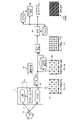
図6は、デプスの計測システム1の概略構成を示す図である。図7は、処理部30の機能ブロック図である。
[2-1. System configuration]
FIG. 6 is a diagram showing a schematic configuration of the
計測システム1は、投光部10、受光部20、処理部30および記憶部50を有する。
The
投光部10は、例えば、アクチュエータ11と光源12とを含む(図15参照)。光源12は、参照光PLを出力するレーザまたはプロジェクタである。アクチュエータ11は、光源12から出力された参照光PLを被写体SU上でスキャンするスキャナである。参照光PLは、例えば、正弦波でモジュレーションされた赤外線である。
The
受光部20は、例えば、x方向およびy方向に配列された複数の画素PX(図14参照)を有するイメージセンサである。画素PXの配列方向と直交するz方向がデプス方向である。画素PXには、参照光PLを検知する受光素子が設けられている。受光部20は、被写体SUで反射された参照光PL(反射光RL)を受光する。
The
投光部10は、参照光PLとして、複数のドットDTが一定の間隔で2次元配列されたドットパターンPATを投射する。投光部10は、ドットパターンPATの投射位置IPを予め設定された計測期間(1フレーム)ごとにシフトさせながら、被写体SU全体を参照光PLで高密度にスキャンする。投射位置IPは、直接反射光DRを用いたデプスの計測が行われる計測対象位置TAである。
The
受光部20は、投射位置IPの切り替えに合わせて参照光PLを受光する。受光部20は、1計測期間の受光データを、参照光PLの飛行時間の計測結果を示すフレームデータとして処理部30に出力する。受光部20は、参照光PLのスキャンが完了するまでフレームデータを生成し続け、生成されたフレームデータを順次処理部30に出力する。
The
フレームデータは、1計測期間に計測された各画素PXの時系列の輝度データである。フレームデータは、ドットパターンPATの投射位置IPおよび非投射位置NIPの輝度データを含む。投射位置IPは、ドットパターンPATが直射する被写体SU上の位置である。非投射位置NIPは、ドットパターンPATが直射しない被写体SU上の位置である。投射位置IPの参照光PLの輝度データは、直接反射光DRとマルチパス光MRの双方の輝度データを含む。非投射位置NIPの参照光PLの輝度データは、マルチパス光MRの輝度データのみを含み、直接反射光DRの輝度データは含まない。 The frame data is time-series luminance data of each pixel PX measured in one measurement period. The frame data includes brightness data of the projection position IP and non-projection position NIP of the dot pattern PAT. The projection position IP is a position on the subject SU where the dot pattern PAT is directly projected. The non-projection position NIP is a position on the subject SU where the dot pattern PAT is not directly projected. The brightness data of the reference light PL at the projection position IP includes brightness data of both the direct reflected light DR and the multipath light MR. The brightness data of the reference light PL at the non-projection position NIP includes only the brightness data of the multipath light MR and does not include the brightness data of the directly reflected light DR.
処理部30は、各種情報を処理する情報処理装置である。処理部30は、投光部10および受光部20を同期して駆動し、受光部20から取得したフレームデータに基づいてデプスマップDM(図8参照)を生成する。
The
処理部30は、データ取得部31、デプス推定部32、デプス補正部33、投射制御部34および打ち切り判定部35を有する。
The
投射制御部34は、制御計画CP(図15参照)に基づいて光源12およびアクチュエータ11の動作を制御する。制御計画CPには、参照光PLのパターン形状、投射位置IPおよび投射タイミングなどの情報が含まれる。投射制御部34は、制御計画CPに基づいて、ドットパターンPATの投射位置IPを1計測期間ごとにシフトさせながら、被写体SU全体を参照光PLで高密度にスキャンする。
The projection control unit 34 controls the operations of the
データ取得部31は、投射位置IPの切り替えに合わせて受光部20から1計測期間ごとに順次フレームデータを取得する。デプス推定部32は、データ取得部31から順次取得される複数のフレームデータに基づいて、複数のデプスマップDMを順次生成する。
The data acquisition unit 31 sequentially acquires frame data from the
例えば、デプス推定部32は、フレームデータから、各画素PXの参照光PLの輝度データを抽出する。デプス推定部32は、反射光RLの位相差から求まる到達時間の遅れから参照光PLの飛行時間(参照光PLが投射されてから、被写体SUで反射されて受光部20で受光されるまでの時間)を間接的に検出する(iToF方式)。デプス推定部32は、飛行時間に基づいて被写体SUのデプスを画素PXごとに推定する。
For example, the
フレームデータには、投射位置IPおよび非投射位置NIPを含む被写体SU全体の参照光PLの輝度データが含まれる。デプス推定部32は、フレームデータに基づいて、各画素PXのデプスを推定する。これにより、参照光PLが投射された投射位置IPおよび投射位置IPからずれた非投射位置NIPの双方のデプスが推定される。
The frame data includes luminance data of the reference light PL for the entire subject SU including the projection position IP and the non-projection position NIP. The
デプス補正部33は、参照光PLが計測対象位置TAに投射されたときに得られる計測対象位置TAのデプスの推定値を、デプスの真値と、マルチパス光MRに起因するエラー成分と、を含む混合デプス値と推定する。デプス補正部33は、参照光PLが計測対象位置TAからずれた位置に投射されたときに得られる計測対象位置TAのデプスの推定値をエラー成分と推定する。デプス補正部33は、デプス推定部32で順次生成された複数のデプスマップDMから、エラー成分と推定されたデプス値の情報をエラー成分情報として抽出する。デプス補正部33は、混合デプス値からエラー成分を除去することで、混合デプス値をエラー成分に基づいて補正する。
The
デプス補正部33は、エラー成分情報に基づいて複数のデプスマップDMから抽出された真値の情報を合成して合成デプスマップADMを生成する。例えば、デプス補正部33は、デプス推定部32で生成された最新のデプスマップDMをエラー成分情報に基づいて補正する。デプス補正部33は、補正された最新のデプスマップDMを直近の合成デプスマップADMと合成する。直近の合成デプスマップADMは、前回までの複数の計測期間のフレームデータに基づいて生成された合成デプスマップADMである。デプス補正部33は、参照光PLのスキャンが完了するまで、1計測期間ごとにデプスマップDMの補正および合成を繰り返す。これにより、合成デプスマップADMの密度が順次高められる。
The
[2-2.合成デプスマップの高密度化]
図8は、合成デプスマップADMが高密度化される過程を示す図である。
[2-2. Densification of synthetic depth map]
FIG. 8 is a diagram showing the process of densifying the composite depth map ADM.
1回目の計測期間に生成される第1デプスマップDM1は、ドットパターンPATに対応した疎らなデプスマップDMである。計測システム1は、ドットパターンPATの投射位置IPをずらしながら順次デプスマップDMを生成する。最新のデプスマップDMは、エラー成分情報に基づいて補正された後、直近の合成デプスマップADMと合成される。これにより、直近の合成デプスマップADMに最新の計測対象位置TAのデプスの情報を付加した新たな合成デプスマップADMが生成される。
The first depth map DM1 generated in the first measurement period is a sparse depth map DM corresponding to the dot pattern PAT. The
ドットパターンPATに含まれるドットDTの数をqとすると、1回の計測でq箇所の被写体SUのデプスの情報が得られる。Q回目の計測では、q×Q箇所の被写体SUのデプスの情報を含む合成デプスマップADMが生成される。疎らなドットパターンPATを用いても、計測を繰り返すことで、デプスの情報が累積された高密度な合成デプスマップADMが生成される。 If the number of dots DT included in the dot pattern PAT is q, depth information of the subject SU at q locations can be obtained by one measurement. In the Q-th measurement, a synthetic depth map ADM including information on the depth of the subject SU at q×Q locations is generated. Even if a sparse dot pattern PAT is used, repeated measurements generate a high-density synthetic depth map ADM in which depth information is accumulated.
[2-3.マルチパス成分の除去原理]
図9ないし図12は、マルチパス成分の除去原理を説明する図である。
[2-3. Elimination Principle of Multipath Components]
9 to 12 are diagrams for explaining the principle of removing multipath components.
投射制御部34は、被写体SU上に、デプスの計測対象となる複数の計測対象位置TAを設定する。投射制御部34は、ドットパターンPATの投射位置IPを1計測期間ごとにずらすことにより、全計測対象位置TAへの参照光PLの投射を複数回に分けて行う。 The projection control unit 34 sets a plurality of measurement target positions TA whose depth is to be measured on the subject SU. The projection control unit 34 divides the projection of the reference light PL onto all the measurement target positions TA into a plurality of times by shifting the projection position IP of the dot pattern PAT for each measurement period.
例えば、投射制御部34は、全計測対象位置TAを、参照光PLの投射タイミングに基づいて複数の位相グループに分類する。同一の位相グループに属する複数の計測対象位置TAには、同じタイミングで参照光PLが投射される。投射制御部34は、参照光PLの投射を1位相グループずつ順番に実施する。 For example, the projection control unit 34 classifies all measurement target positions TA into a plurality of phase groups based on the projection timing of the reference light PL. The reference beam PL is projected at the same timing on a plurality of measurement target positions TA belonging to the same phase group. The projection control unit 34 sequentially projects the reference light PL for each phase group.
図9の例では、複数の計測対象位置TAが、奇数位相と偶数位相の2つの位相グループに分類される。1回目の計測では、奇数位相に分類された複数の計測対象位置TA(奇数位相位置TAodd)が投射位置IPとなる。偶数位相に分類された複数の計測対象位置TA(偶数位相位置TAeven)は、ドットパターンPATが投射(直射)されない非投射位置NIPとなる。2回目の計測では、偶数位相位置TAevenが投射位置IPとなり、奇数位相位置TAoddは非投射位置NIPとなる。 In the example of FIG. 9, a plurality of measurement target positions TA are classified into two phase groups of odd-numbered phases and even-numbered phases. In the first measurement, a plurality of measurement target positions TA classified as odd phases (odd phase positions TA odd ) are projection positions IP. A plurality of measurement target positions TA classified as even phases (even phase positions TA even ) are non-projection positions NIP where the dot pattern PAT is not projected (directly). In the second measurement, the even phase position TA even becomes the projected position IP and the odd phase position TA odd becomes the non-projected position NIP.
図10および図11に示すように、受光部20の複数の画素PXは、複数の奇数位相位置TAoddを計測する複数の奇数位相画素PXoddと、複数の偶数位相位置TAevenを計測する複数の偶数位相画素PXevenと、に分類される。奇数位相画素PXoddには、奇数位相位置TAoddが投射位置IPとなったときに、奇数位相位置TAoddからの直接反射光DRが入射する。偶数位相画素PXevenには、偶数位相位置TAevenが投射位置IPとなったときに、偶数位相位置TAevenからの直接反射光DRが入射する。
As shown in FIGS. 10 and 11 , the plurality of pixels PX of the
1回目の計測では、複数の奇数位相位置TAoddが投射位置IPとなる。そのため、図10に示すように、奇数位相画素PXoddには、投射位置IPである奇数位相位置TAoddで反射した直接反射光DRと、高反射物体HRで反射したマルチパス光MRと、が入射する。一方、図11に示すように、偶数位相画素PXevenには、高反射物体HRで反射したマルチパス光MRのみが入射する。投射位置IPが偶数位相位置TAevenではないため(偶数位相位置TAevenは非投射位置NIP)、投射位置IPで反射した直接反射光DRは偶数位相画素PXevenには入射しない。 In the first measurement, a plurality of odd-numbered phase positions TA odd are projected positions IP. Therefore, as shown in FIG. 10, the odd-numbered phase pixel PX odd receives the direct reflected light DR reflected at the odd-numbered phase position TA odd , which is the projection position IP, and the multipath light MR reflected by the highly reflective object HR. Incident. On the other hand, as shown in FIG. 11, only the multipath light MR reflected by the highly reflective object HR is incident on the even phase pixel PX even . Since the projection position IP is not the even phase position TA even (the even phase position TA even is the non-projection position NIP), the direct reflected light DR reflected at the projection position IP does not enter the even phase pixels PX even .
上述のように、エラー成分であるマルチパス光MRは、奇数位相画素PXoddと偶数位相画素PXevenの双方で計測される。デプスの真値を示す直接反射光DRは、奇数位相画素PXoddのみで計測される。計測システム1は、投射タイミングと各位相グループの計測データとの関係に基づいて、各計測対象位置TAのデプスを推定する。
As described above, the multipath light MR, which is an error component, is measured by both the odd phase pixels PX odd and the even phase pixels PX even . The directly reflected light DR indicating the true depth value is measured only by the odd-numbered phase pixels PX odd . The
例えば、図12に示すように、投射制御部34は、ドットパターンPATを複数の奇数位相位置TAoddに投射して1回目の計測を実施する。デプス推定部32は、1回目の計測で得られたフレームデータに基づいて各画素PXのデプスを推定する。デプス推定部32は、各画素PXのデプスの推定値に基づいて第1デプスマップDM1を生成する。デプス補正部33は、各偶数位相画素PXeven(k,l)のデプス値deven,k,l(k,l:画素のx、y座標)を、マルチパス光MRに起因するエラー成分と推定する。デプス補正部33は、各奇数位相画素PXodd(i,j)のデプス値dodd,i,j(i,j:画素のx、y座標)を、真値およびエラー成分を含む混合デプス値として推定する。
For example, as shown in FIG. 12, the projection control unit 34 projects the dot pattern PAT to a plurality of odd-numbered phase positions TA odd to perform the first measurement. The
次に、投射制御部34は、ドットパターンPATを複数の偶数位相位置TAevenに投射して2回目の計測を実施する。デプス推定部32は、2回目の計測で得られたフレームデータに基づいて各画素PXのデプスを推定する。デプス推定部32は、各画素PXのデプスの推定値に基づいて第2デプスマップDM2を生成する。デプス補正部33は、各奇数位相画素PXodd(i,j)のデプス値dodd,i,jを、マルチパス光MRに起因するエラー成分と推定する。デプス補正部33は、各偶数位相画素PXeven(k,l)のデプス値deven,k,lを、真値およびエラー成分を含む混合デプス値として推定する。
Next, the projection control unit 34 projects the dot pattern PAT to a plurality of even-numbered phase positions TA even to perform the second measurement. The
デプス補正部33は、第1デプスマップDM1および第2デプスマップDM2から、エラー成分と推定されたデプス値の情報をエラー成分情報として抽出する。デプス補正部33は、エラー成分情報に基づいて第1デプスマップDM1および第2デプスマップDM2を補正する。
The
例えば、デプス補正部33は、第1デプスマップDM1に含まれる奇数位相画素PXodd(i,j)のデプス値dodd,i,jから、下記式(1)に基づいて、エラー成分である、第2デプスマップDM2に含まれる同じ奇数位相画素PXodd(i,j)のデプス値dodd,i,jを減算する。
For example, the
![]()
![]()
デプス補正部33は、第2デプスマップDM2に含まれる偶数位相画素PXeven(k,l)のデプス値deven,k,lから、下記式(2)に基づいて、エラー成分である、第1デプスマップDM1に含まれる同じ偶数位相画素PXeven(k,l)のデプス値deven,k,lを減算する。 The depth correction unit 33 calculates the error component, the first Subtract the depth values d even,k,l of the same even-phase pixel PX even (k,l) included in one depth map DM1.
![]()
![]()
デプス補正部33は、補正後の第1デプスマップDM1と補正後の第2デプスマップDM2とを合成し、エラー成分が除去された高密度な合成デプスマップADMを生成する。
The
[2-4.打ち切り判定]
上述の例では、位相グループの数(位相数)は、奇数位相と偶数位相の2つである。しかし、位相数は2以上であればよく、3以上とすることもできる。位相数は、全ての計測対象位置TAをスキャンするために必要な計測の回数を示す。位相数が増えれば、デプスマップDMの密度は高くなるが、計測時間は長くなる。被写体SUの形状が単純な場合には、デプスマップDMの密度が小さくても、補間処理などにより被写体SUの形状が精度よく推定できる場合もある。このような場合には、位相数よりも少ない回数で計測を打ち切ることもできる。
[2-4. Abort Judgment]
In the above example, the number of phase groups (number of phases) is two, odd phases and even phases. However, the number of phases should be two or more, and may be three or more. The number of phases indicates the number of measurements required to scan all the measurement target positions TA. As the number of phases increases, the density of the depth map DM increases, but the measurement time increases. When the shape of the subject SU is simple, even if the density of the depth map DM is small, the shape of the subject SU may be accurately estimated by interpolation processing or the like. In such a case, the measurement can be terminated after a number of times less than the number of phases.
例えば、打ち切り判定部35は、1計測期間ごとに生成されるデプスマップDMをデプス補正部33から順次取得する。打ち切り判定部35は、1計測期間ごとに更新されるデプスの推定値の推移に基づいて、計測の打ち切りを判定する。打ち切り判定部35は、デプスの推定値の推移が予め設定された飽和条件を満たす場合には、計測を打ち切ることを決定する。打ち切りが決定された場合には、打ち切り判定部35は、打ち切り情報を投射制御部34およびデータ取得部31に出力する。投射制御部34およびデータ取得部31は、打ち切り情報に基づいて、参照光PLの投射および受光データの取得を停止する。
For example, the discontinuation determination unit 35 sequentially acquires the depth map DM generated for each measurement period from the
図13は、打ち切り判定の一例を示す図である。 FIG. 13 is a diagram showing an example of termination determination.
打ち切り判定部35は、デプスマップDMから被写体SUのジオメトリ情報GIを抽出する。ジオメトリ情報GIは、計測済みの計測対象位置TAのデプスの推定値を用いて演算される。打ち切り判定部35は、最新の計測結果に基づいて、1計測期間ごとにジオメトリ情報GIを更新する。打ち切り判定部35は、更新の前後のジオメトリ情報GIの変化を検出する。打ち切り判定部35は、ジオメトリ情報GIの変化に基づいて、デプスの推定値の推移が飽和条件を満たすか否かを判定する。飽和条件が満たされる場合には、計測の打ち切りが決定される。 The discontinuation determination unit 35 extracts the geometry information GI of the subject SU from the depth map DM. The geometry information GI is calculated using the estimated value of the depth of the measurement target position TA that has already been measured. The discontinuation determination unit 35 updates the geometry information GI for each measurement period based on the latest measurement result. The discontinuation determination unit 35 detects changes in the geometry information GI before and after updating. The discontinuation determination unit 35 determines whether or not the transition of the estimated depth value satisfies the saturation condition based on the change in the geometry information GI. If the saturation condition is met, it is decided to truncate the measurement.
例えば、打ち切り判定部35は、ジオメトリ情報GIとして、計測済みの各計測対象位置TAにおける被写体SUの法線ベクトルNの情報を抽出する。打ち切り判定部35は、計測済みの全ての計測対象位置TAにおいて、更新の前後の法線ベクトルNの変化(法線ベクトルの差分の大きさ)が、予め設定された閾値以下である場合には(|Nt-Nt+1|≦threshold)、飽和条件が満たされると判定する。なお、符号tは計測回数を示す。「t=n」は、参照光PLの投射がn番目の位相グループまで実施されたことを意味する。 For example, the discontinuation determination unit 35 extracts, as the geometry information GI, information on the normal vector N of the subject SU at each measurement target position TA that has already been measured. If the change in the normal vector N before and after the update (magnitude of the difference in the normal vector) is equal to or less than a preset threshold at all the measurement target positions TA that have already been measured, the discontinuation determination unit 35 (|N t −N t+1 |≦threshold), it is determined that the saturation condition is satisfied. Note that the symbol t indicates the number of measurements. "t=n" means that the projection of the reference beam PL has been performed up to the nth phase group.
図13の上段は、被写体SUの形状が、曲面などの、不規則な凹凸を持たない単純形状である例を示す(シーンA)。シーンAでは、計測回数が、n、(n+1)および(n+2)と増えても、更新される法線ベクトルNの向きに大きな変化は生じない。打ち切り判定部35は、計測の効率化を重視して、計測の打ち切りを決定する。デプス補正部33は、計測が完了していない計測対象位置TAのデプスを、計測済みの他の計測対象位置TAのデプスの推定値に基づいて補間する。
The upper part of FIG. 13 shows an example in which the shape of the subject SU is a simple shape without irregular unevenness, such as a curved surface (scene A). In scene A, even if the number of measurements increases to n, (n+1), and (n+2), the orientation of the updated normal vector N does not change significantly. The discontinuation determination unit 35 determines discontinuation of the measurement with emphasis on efficiency of the measurement. The
図13の下段は、被写体SUの形状が、段差などの凹凸を有する複雑な形状である例を示す(シーンB)。シーンBでは、計測ごとに、法線ベクトルNの向きが大きく変化する。打ち切り判定部35は、計測済みのデータのみでは被写体SUの形状が正確に把握できないと判断し、計測の継続を決定する。 The lower part of FIG. 13 shows an example in which the shape of the subject SU is a complex shape with unevenness such as steps (scene B). In scene B, the direction of the normal vector N changes greatly for each measurement. The discontinuation determination unit 35 determines that the shape of the subject SU cannot be accurately grasped only from the measured data, and determines to continue the measurement.
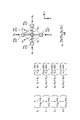
図14は、法線ベクトルNの算出方法の一例を示す図である。 FIG. 14 is a diagram showing an example of a method for calculating the normal vector N.
打ち切り判定部35は、被写体SU上の位置iおける被写体SUの法線ベクトルNを、位置iの3次元座標、および、位置iに隣接する位置j0,j1,j2,j3の3次元座標を用いて算出する。位置i,j0,j1,j2,j3の3次元座標は、各位置に対応した画素PXi,PXj0,PXj1,PXj2,PXj3のxy座標、および、画素PXi,PXj0,PXj1,PXj2,PXj3で検出されたデプスの推定値D(i),D(j0),D(j1),D(j2),D(j3)を用いて算出される。 The discontinuation determination unit 35 determines the normal vector N of the subject SU at the position i on the subject SU from the three-dimensional coordinates of the position i and the positions j 0 , j 1 , j 2 , and j 3 adjacent to the position i. Calculated using dimensional coordinates. The three -dimensional coordinates of the positions i , j0 , j1 , j2 , and j3 are the xy coordinates of the pixels PXi , PXj0 , PXj1, PXj2, and PXj3 corresponding to each position, and the pixels PXi , Using depth estimates D(i), D(j 0 ), D(j 1 ), D(j 2 ), D(j 3 ) detected at PX j0 , PX j1 , PX j2 , PX j3 Calculated.
例えば、打ち切り判定部35は、位置j0,j1,j2,j3から位置iに向かう4つのベクトルS0,S1,S2,S3を算出する。打ち切り判定部35は、位置j0,j1,j2,j3で囲まれた矩形領域を、位置iを頂点とする4つの三角形領域に分割する。打ち切り判定部35は、各三角形領域の法線ベクトルN10,N02,N23,N31を、ベクトルS0,S1,S2,S3を用いて算出する。打ち切り判定部35は、4つの三角形領域の法線ベクトルN10,N02,N23,N31の平均ベクトルを位置iおける法線ベクトルNとして算出する。 For example, the discontinuation determination unit 35 calculates four vectors S 0 , S 1 , S 2 , S 3 directed from the positions j 0 , j 1 , j 2 , j 3 to the position i. The discontinuation determining unit 35 divides the rectangular area surrounded by the positions j 0 , j 1 , j 2 , and j 3 into four triangular areas with the position i as the vertex. The discontinuation determining unit 35 calculates normal vectors N 10 , N 02 , N 23 and N 31 of each triangular region using the vectors S 0 , S 1 , S 2 and S 3 . The discontinuation determination unit 35 calculates the average vector of the normal vectors N 10 , N 02 , N 23 and N 31 of the four triangular regions as the normal vector N at the position i.
上述した各種条件、および、閾値などの基準に関する情報は、設定情報51に含まれる。上述の処理に用いられる設定情報51およびプログラム59は記憶部50に記憶される。プログラム59は、本実施形態に係る情報処理をコンピュータに実行させるプログラムである。処理部30は、記憶部50に記憶されているプログラム59にしたがって各種の処理を行う。記憶部50は、処理部30の処理結果を一時的に記憶する作業領域(バッファ)として利用されてもよい。記憶部50は、例えば、半導体記憶媒体および磁気記憶媒体などの任意の非一過的な記憶媒体を含む。記憶部50は、例えば、光ディスク、光磁気ディスクまたはフラッシュメモリを含んで構成される。プログラム59は、例えば、コンピュータにより読み取り可能な非一過的な記憶媒体に記憶されている。
The setting
処理部30は、例えば、プロセッサとメモリとで構成されるコンピュータである。処理部30のメモリには、RAM(Random Access Memory)およびROM(Read Only Memory)が含まれる。処理部30は、プログラム59を実行することにより、データ取得部31、デプス推定部32、デプス補正部33、投射制御部34および打ち切り判定部35として機能する。
The
[3.情報処理方法]
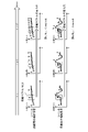
図15および図16は、デプスの推定に関わる情報処理の一例を示す図である。
[3. Information processing method]
15 and 16 are diagrams illustrating an example of information processing related to depth estimation.
ステップS1において、投射制御部34は、位相グループの番号(グループ番号)nを1に設定する。ステップS2において、投射制御部34は、グループ番号nが位相数より小さいか否かを判定する。ステップS2において、グループ番号nが位相数と同じであると判定された場合には(ステップS2:No)、処理を終了する。ステップS2において、グループ番号nが位相数よりも小さいと判定された場合には(ステップS2:No)、ステップS3に進む。ステップS3において、投射制御部34は、グループ番号nに対応する複数の計測対象位置TAが投射位置IPとなるように投光部10を制御する。
In step S1, the projection control unit 34 sets the phase group number (group number) n to 1. In step S2, the projection control section 34 determines whether or not the group number n is smaller than the number of phases. If it is determined in step S2 that the group number n is the same as the number of phases (step S2: No), the process ends. If it is determined in step S2 that the group number n is smaller than the number of phases (step S2: No), the process proceeds to step S3. In step S3, the projection control unit 34 controls the
ステップS4において、投光部10は、投射制御部34によって制御されたタイミングで、グループ番号nに対応する複数の計測対象位置TAに参照光PLを投射する。受光部20は、被写体SUで反射した参照光PLを受光し、各画素PXで計測された参照光PLの輝度データをフレームデータとして出力する。デプス推定部32は、フレームデータに基づいて、デプスマップDM(第1デプスマップDM1)を生成する。
In step S4, the
ステップS5において、投射制御部34は、次のグループ番号nに対応する複数の計測対象位置TAが投射位置IPとなるように投光部10を制御する。図15の例では、全ての計測対象位置TAが奇数位相と偶数位相に分けられる。そのため、2回目の投射位置IPは1回目の投射位置IPの逆位相となる。
In step S5, the projection control unit 34 controls the
ステップS6において、投光部10は、投射制御部34によって制御されたタイミングで、次のグループ番号nに対応する複数の計測対象位置TAに参照光PLを投射する。受光部20は、被写体SUで反射した参照光PLを受光し、各画素PXで計測された参照光PLの輝度データをフレームデータとして出力する。デプス推定部32は、フレームデータに基づいて、デプスマップDM(第2デプスマップDM2)を生成する。
In step S6, the
ステップS7において、デプス補正部33は、第1デプスマップDM1および第2デプスマップDM2からエラー成分情報を抽出する。デプス補正部33は、エラー成分情報に基づいて、第1デプスマップDM1および第2デプスマップDM2を補正する。ステップS8において、デプス補正部33は、補正後の第1デプスマップDM1と補正後の第2デプスマップDM2とを合成し、合成デプスマップADMを生成する。
In step S7, the
図15の例では、計測対象位置TAが2つの位相グループに分類されるため、計測は2回で終了する。しかし、計測対象位置TAが3以上の位相グループに分類される場合には、ステップS9において、打ち切り判定が実施される。打ち切り判定部35は、補正後の第1デプスマップDM1と合成デプスマップADMの双方から被写体SUのジオメトリ情報GIを抽出する。打ち切り判定部35は、最新の計測結果に基づいて1計測期間ごとに更新されるジオメトリ情報GIの変化を飽和条件に当てはめる。
に基づいて、計測を打ち切るか否かを判定する。
In the example of FIG. 15, the measurement target position TA is classified into two phase groups, so the measurement is completed twice. However, when the measurement target position TA is classified into three or more phase groups, discontinuation determination is performed in step S9. The discontinuation determination unit 35 extracts the geometry information GI of the subject SU from both the corrected first depth map DM1 and the combined depth map ADM. The discontinuation determination unit 35 applies changes in the geometry information GI updated every measurement period based on the latest measurement result to the saturation condition.
Based on, it is determined whether or not to terminate the measurement.
ステップS10において、打ち切り判定部35は、ジオメトリ情報GIの変化に基づいて、計測を打ち切るか否かを判定する。ステップS10において、打ち切りが決定された場合には(ステップS10:Yes)、処理部30は処理を終了する。計測の打ち切りにより、計測が完了していない計測対象位置TAのデプスは、計測済みの他の計測対象位置TAのデプスの推定値に基づいて補間される。
In step S10, the discontinuation determination unit 35 determines whether or not to discontinue measurement based on changes in the geometry information GI. In step S10, when the termination is determined (step S10: Yes), the
ステップS10において、計測の継続が決定された場合には(ステップS10:No)、ステップS11に進む。ステップS11において、処理部30は、グループ番号nを1つ先に進め、打ち切りが決定されるまで上述した処理を繰り返す。
In step S10, if it is determined to continue the measurement (step S10: No), the process proceeds to step S11. In step S11, the
[4.効果]
処理部30は、デプス推定部32とデプス補正部33とを有する。デプス推定部32は、参照光PLの飛行時間の計測結果に基づいて、参照光PLが投射された投射位置IPおよび投射位置IPからずれた非投射位置NIPのデプスを推定する。デプス補正部33は、参照光PLが被写体SUの計測対象位置TAからずれた位置に投射されたときに得られる計測対象位置TAのデプスの推定値をエラー成分として抽出する。デプス補正部33は、参照光PLが計測対象位置TAに投射されたときに得られる計測対象位置TAのデプスの推定値からエラー成分を除去する。本実施形態の情報処理方法は、上述した処理部30の処理がコンピュータにより実行される。本実施形態のプログラムは、上述した処理部30の処理をコンピュータに実現させる。
[4. effect]
The
この構成によれば、マルチパス光MRに起因するエラー成分が良好に除去される。そのため、高精度なデプスの情報が得られる。 According to this configuration, the error component caused by the multipath light MR is removed satisfactorily. Therefore, highly accurate depth information can be obtained.
処理部30は、投射制御部34を有する。投射制御部34は、参照光PLの投射位置IPを1計測期間ごとにシフトさせながら、被写体SUを参照光PLでスキャンする。
The
この構成によれば、被写体SUを参照光PLで高密度にスキャンすることができる。 According to this configuration, the subject SU can be scanned with the reference light PL at high density.
投射制御部34は、参照光PLを、複数のドットDTが2次元配列されたドットパターンPATとして投射する。 The projection control unit 34 projects the reference light PL as a dot pattern PAT in which a plurality of dots DT are two-dimensionally arranged.
この構成によれば、一度に複数の計測対象位置TAのデプスの計測が行われる。 According to this configuration, the depth measurement of a plurality of measurement target positions TA is performed at once.
デプス推定部32は、投射位置IPの切り替えに合わせて1計測期間ごとに取得された複数の参照光PLの受光データに基づいて複数のデプスマップDMを生成する。デプス補正部33は、複数のデプスマップDMから、エラー成分と推定されたデプス値の情報をエラー成分情報として抽出する。デプス補正部33は、エラー成分情報に基づいて複数のデプスマップDMから真値の情報を抽出する。デプス補正部33は、抽出された真値の情報を合成して合成デプスマップADMを生成する。
The
この構成によれば、計測ごとにデプスの情報が累積された高密度な合成デプスマップADMが生成される。 According to this configuration, a high-density synthetic depth map ADM in which depth information is accumulated for each measurement is generated.
処理部30は、打ち切り判定部35を有する。打ち切り判定部35は、合成デプスマップADMから被写体SUのジオメトリ情報GIを抽出する。打ち切り判定部35は、最新の計測結果に基づいて1計測期間ごとに更新されるジオメトリ情報GIの変化に基づいて、計測を打ち切るか否かを判定する。
The
この構成によれば、計測時間が必要以上に長期化されることが抑制される。 According to this configuration, it is possible to prevent the measurement time from becoming longer than necessary.
デプス補正部33は、計測の打ち切りにより計測が完了していない計測対象位置TAのデプスを、計測済みの他の計測対象位置TAのデプスの推定値に基づいて補間する。
The
この構成によれば、計測が打ち切られてもデプスの情報の密度が低下しない。 According to this configuration, the density of depth information does not decrease even if measurement is discontinued.
なお、本明細書に記載された効果はあくまで例示であって限定されるものでは無く、また他の効果があってもよい。 It should be noted that the effects described in this specification are only examples and are not limited, and other effects may also occur.
[付記]
なお、本技術は以下のような構成も取ることができる。
(1)
参照光の飛行時間の計測結果に基づいて、前記参照光が投射された投射位置および前記投射位置からずれた非投射位置のデプスを推定するデプス推定部と、
前記参照光が被写体の計測対象位置からずれた位置に投射されたときに得られる前記計測対象位置のデプスの推定値をエラー成分として抽出し、前記参照光が前記計測対象位置に投射されたときに得られる前記計測対象位置のデプスの推定値から前記エラー成分を除去するデプス補正部と、
を有する情報処理装置。
(2)
前記参照光の投射位置を1計測期間ごとにシフトさせながら、前記被写体を前記参照光でスキャンする投射制御部を有する、
上記(1)に記載の情報処理装置。
(3)
前記投射制御部は、前記参照光を、複数のドットが2次元配列されたドットパターンとして投射する、
上記(2)に記載の情報処理装置。
(4)
前記デプス推定部は、前記投射位置の切り替えに合わせて1計測期間ごとに取得された複数の前記参照光の受光データに基づいて複数のデプスマップを生成し、
前記デプス補正部は、前記複数のデプスマップから、前記エラー成分と推定されたデプス値の情報をエラー成分情報として抽出し、前記エラー成分情報に基づいて前記複数のデプスマップから抽出された真値の情報を合成して合成デプスマップを生成する、
上記(2)または(3)に記載の情報処理装置。
(5)
前記合成デプスマップから前記被写体のジオメトリ情報を抽出し、最新の計測結果に基づいて1計測期間ごとに更新される前記ジオメトリ情報の変化に基づいて、計測を打ち切るか否かを判定する打ち切り判定部を有する、
上記(4)に記載の情報処理装置。
(6)
前記デプス補正部は、計測の打ち切りにより計測が完了していない前記計測対象位置のデプスを、計測済みの他の前記計測対象位置のデプスの推定値に基づいて補間する、
上記(5)に記載の情報処理装置。
(7)
参照光の飛行時間の計測結果に基づいて、前記参照光が投射された投射位置および前記投射位置からずれた非投射位置のデプスを推定し、
前記参照光が被写体の計測対象位置からずれた位置に投射されたときに得られる前記計測対象位置のデプスの推定値をエラー成分として抽出し、
前記参照光が前記計測対象位置に投射されたときに得られる前記計測対象位置のデプスの推定値から前記エラー成分を除去する、
ことを有する、コンピュータにより実行される情報処理方法。
(8)
参照光の飛行時間の計測結果に基づいて、前記参照光が投射された投射位置および前記投射位置からずれた非投射位置のデプスを推定し、
前記参照光が被写体の計測対象位置からずれた位置に投射されたときに得られる前記計測対象位置のデプスの推定値をエラー成分として抽出し、
前記参照光が前記計測対象位置に投射されたときに得られる前記計測対象位置のデプスの推定値から前記エラー成分を除去する、
ことをコンピュータに実現させるプログラム。
[Appendix]
Note that the present technology can also take the following configuration.
(1)
a depth estimating unit that estimates the depth of a projection position where the reference light is projected and a non-projection position shifted from the projection position based on the measurement result of the time of flight of the reference light;
When the reference light is projected onto the measurement target position, an estimated value of the depth of the measurement target position obtained when the reference light is projected to the measurement target position of the subject is extracted as an error component, and the reference light is projected onto the measurement target position. a depth correction unit that removes the error component from the estimated value of the depth of the measurement target position obtained in
Information processing device having
(2)
a projection control unit that scans the subject with the reference light while shifting the projection position of the reference light for each measurement period;
The information processing apparatus according to (1) above.
(3)
The projection control unit projects the reference light as a dot pattern in which a plurality of dots are arranged two-dimensionally.
The information processing apparatus according to (2) above.
(4)
The depth estimating unit generates a plurality of depth maps based on a plurality of received light data of the reference light acquired for each measurement period in accordance with the switching of the projection position,
The depth correction unit extracts information of the depth value estimated as the error component from the plurality of depth maps as error component information, and extracts a true value extracted from the plurality of depth maps based on the error component information. generate a synthetic depth map by synthesizing information from
The information processing apparatus according to (2) or (3) above.
(5)
A discontinuation determination unit that extracts geometry information of the subject from the synthetic depth map and determines whether or not to discontinue measurement based on changes in the geometry information that is updated every measurement period based on the latest measurement results. having
The information processing apparatus according to (4) above.
(6)
The depth correction unit interpolates the depth of the measurement target position for which measurement has not been completed due to discontinuation of measurement, based on an estimated value of the depth of the other measurement target position that has already been measured.
The information processing apparatus according to (5) above.
(7)
estimating the depth of a projection position where the reference light is projected and a non-projection position shifted from the projection position based on the measurement result of the flight time of the reference light;
extracting, as an error component, an estimated value of the depth of the measurement target position obtained when the reference light is projected at a position shifted from the measurement target position of the object;
removing the error component from an estimated value of the depth of the measurement target position obtained when the reference light is projected onto the measurement target position;
A computer-implemented information processing method, comprising:
(8)
estimating the depth of a projection position where the reference light is projected and a non-projection position shifted from the projection position based on the measurement result of the flight time of the reference light;
extracting, as an error component, an estimated value of the depth of the measurement target position obtained when the reference light is projected at a position shifted from the measurement target position of the object;
removing the error component from an estimated value of the depth of the measurement target position obtained when the reference light is projected onto the measurement target position;
A program that makes a computer do something.
30 処理部(情報処理装置)
32 デプス推定部
33 デプス補正部
34 投射制御部
35 打ち切り判定部
59 プログラム
ADM 合成デプスマップ
DM デプスマップ
DT ドット
GI ジオメトリ情報
IP 投射位置
NIP 非投射位置
PAT ドットパターン
PL 参照光
SU 被写体
TA 計測対象位置
30 processing unit (information processing device)
32
Claims (8)
前記参照光が被写体の計測対象位置からずれた位置に投射されたときに得られる前記計測対象位置のデプスの推定値をエラー成分として抽出し、前記参照光が前記計測対象位置に投射されたときに得られる前記計測対象位置のデプスの推定値から前記エラー成分を除去するデプス補正部と、
を有する情報処理装置。 a depth estimating unit that estimates the depth of a projection position where the reference light is projected and a non-projection position shifted from the projection position based on the measurement result of the time of flight of the reference light;
When the reference light is projected onto the measurement target position, an estimated value of the depth of the measurement target position obtained when the reference light is projected to the measurement target position of the subject is extracted as an error component, and the reference light is projected onto the measurement target position. a depth correction unit that removes the error component from the estimated value of the depth of the measurement target position obtained in
Information processing device having
請求項1に記載の情報処理装置。 a projection control unit that scans the subject with the reference light while shifting the projection position of the reference light for each measurement period;
The information processing device according to claim 1 .
請求項2に記載の情報処理装置。 The projection control unit projects the reference light as a dot pattern in which a plurality of dots are arranged two-dimensionally.
The information processing apparatus according to claim 2.
前記デプス補正部は、前記複数のデプスマップから、前記エラー成分と推定されたデプス値の情報をエラー成分情報として抽出し、前記エラー成分情報に基づいて前記複数のデプスマップから抽出された真値の情報を合成して合成デプスマップを生成する、
請求項2に記載の情報処理装置。 The depth estimating unit generates a plurality of depth maps based on a plurality of received light data of the reference light acquired for each measurement period in accordance with the switching of the projection position,
The depth correction unit extracts information of the depth value estimated as the error component from the plurality of depth maps as error component information, and extracts a true value extracted from the plurality of depth maps based on the error component information. generate a synthetic depth map by synthesizing information from
The information processing apparatus according to claim 2.
請求項4に記載の情報処理装置。 A discontinuation determination unit that extracts geometry information of the subject from the synthetic depth map and determines whether or not to discontinue measurement based on changes in the geometry information that is updated every measurement period based on the latest measurement results. having
The information processing apparatus according to claim 4.
請求項5に記載の情報処理装置。 The depth correction unit interpolates the depth of the measurement target position for which measurement has not been completed due to discontinuation of measurement, based on an estimated value of the depth of the other measurement target position that has already been measured.
The information processing device according to claim 5 .
前記参照光が被写体の計測対象位置からずれた位置に投射されたときに得られる前記計測対象位置のデプスの推定値をエラー成分として抽出し、
前記参照光が前記計測対象位置に投射されたときに得られる前記計測対象位置のデプスの推定値から前記エラー成分を除去する、
ことを有する、コンピュータにより実行される情報処理方法。 estimating the depth of a projection position where the reference light is projected and a non-projection position shifted from the projection position based on the measurement result of the flight time of the reference light;
extracting, as an error component, an estimated value of the depth of the measurement target position obtained when the reference light is projected at a position shifted from the measurement target position of the object;
removing the error component from an estimated value of the depth of the measurement target position obtained when the reference light is projected onto the measurement target position;
A computer-implemented information processing method, comprising:
前記参照光が被写体の計測対象位置からずれた位置に投射されたときに得られる前記計測対象位置のデプスの推定値をエラー成分として抽出し、
前記参照光が前記計測対象位置に投射されたときに得られる前記計測対象位置のデプスの推定値から前記エラー成分を除去する、
ことをコンピュータに実現させるプログラム。 estimating the depth of a projection position where the reference light is projected and a non-projection position shifted from the projection position based on the measurement result of the flight time of the reference light;
extracting, as an error component, an estimated value of the depth of the measurement target position obtained when the reference light is projected at a position shifted from the measurement target position of the object;
removing the error component from an estimated value of the depth of the measurement target position obtained when the reference light is projected onto the measurement target position;
A program that makes a computer do something.
Applications Claiming Priority (2)
| Application Number | Priority Date | Filing Date | Title |
|---|---|---|---|
| JP2021047238 | 2021-03-22 | ||
| JP2021-047238 | 2021-03-22 |
Publications (1)
| Publication Number | Publication Date |
|---|---|
| WO2022201848A1 true WO2022201848A1 (en) | 2022-09-29 |
Family
ID=83395407
Family Applications (1)
| Application Number | Title | Priority Date | Filing Date |
|---|---|---|---|
| PCT/JP2022/003234 Ceased WO2022201848A1 (en) | 2021-03-22 | 2022-01-28 | Information processing device, information processing method, and program |
Country Status (1)
| Country | Link |
|---|---|
| WO (1) | WO2022201848A1 (en) |
Citations (4)
| Publication number | Priority date | Publication date | Assignee | Title |
|---|---|---|---|---|
| WO2006118286A1 (en) * | 2005-05-02 | 2006-11-09 | Matsushita Electric Works, Ltd. | Space information detecting device, and space information detecting system using the device |
| US20130148102A1 (en) * | 2011-12-12 | 2013-06-13 | Mesa Imaging Ag | Method to Compensate for Errors in Time-of-Flight Range Cameras Caused by Multiple Reflections |
| JP2019529924A (en) * | 2016-09-30 | 2019-10-17 | マジック リープ, インコーポレイテッドMagic Leap,Inc. | Projector with spatial light modulation |
| JP2021039131A (en) * | 2014-06-11 | 2021-03-11 | ソニー デプスセンシング ソリューションズ エスエー エヌブイ | Tof camera system and method for measuring distance by system |
-
2022
- 2022-01-28 WO PCT/JP2022/003234 patent/WO2022201848A1/en not_active Ceased
Patent Citations (4)
| Publication number | Priority date | Publication date | Assignee | Title |
|---|---|---|---|---|
| WO2006118286A1 (en) * | 2005-05-02 | 2006-11-09 | Matsushita Electric Works, Ltd. | Space information detecting device, and space information detecting system using the device |
| US20130148102A1 (en) * | 2011-12-12 | 2013-06-13 | Mesa Imaging Ag | Method to Compensate for Errors in Time-of-Flight Range Cameras Caused by Multiple Reflections |
| JP2021039131A (en) * | 2014-06-11 | 2021-03-11 | ソニー デプスセンシング ソリューションズ エスエー エヌブイ | Tof camera system and method for measuring distance by system |
| JP2019529924A (en) * | 2016-09-30 | 2019-10-17 | マジック リープ, インコーポレイテッドMagic Leap,Inc. | Projector with spatial light modulation |
Similar Documents
| Publication | Publication Date | Title |
|---|---|---|
| JP5632762B2 (en) | POSITIONING INFORMATION FORMING DEVICE, DETECTING DEVICE, AND POSITIONING INFORMATION FORMING METHOD | |
| EP2538242B1 (en) | Depth measurement quality enhancement. | |
| JP5132832B1 (en) | Measuring apparatus and information processing apparatus | |
| US9786062B2 (en) | Scene reconstruction from high spatio-angular resolution light fields | |
| US20110285910A1 (en) | Video manipulation of red, green, blue, distance (RGB-Z) data including segmentation, up-sampling, and background substitution techniques | |
| EP2722646A1 (en) | Distance measurement device and environment map generation apparatus | |
| CN106997582A (en) | The motion blur removing method and equipment of flight time three-dimension sensor | |
| EP3832601B1 (en) | Image processing device and three-dimensional measuring system | |
| WO2012120856A1 (en) | Object detection device and object detection method | |
| US9280846B2 (en) | Method, apparatus, and computer-readable recording medium for depth warping based occlusion culling | |
| KR20120068470A (en) | Apparatus for matching stereo image and method thereof | |
| WO2015057098A1 (en) | Motion compensation method and apparatus for depth images | |
| JP2005037378A (en) | Depth measurement method and depth measurement device | |
| CN110189265B (en) | Distance energy correlation three-dimensional imaging super pixel repairing method | |
| JPWO2022239573A5 (en) | ||
| JP4394487B2 (en) | Stereo image processing device | |
| JP2001194126A (en) | Three-dimensional shape measuring device, three-dimensional shape measuring method, and program providing medium | |
| KR20090068943A (en) | Cost function calculation method and hidden region processing method for variance estimation | |
| KR102543027B1 (en) | Method and apparatus for obtaining 3 dimentional image | |
| WO2022201848A1 (en) | Information processing device, information processing method, and program | |
| JP2004508641A (en) | Digital image segmentation | |
| US8897547B2 (en) | Precision improving device for three dimensional topographical data, precision improving method for three dimensional topographical data and recording medium | |
| JP2001324313A (en) | Three-dimensional shape measuring instrument | |
| Fong et al. | High-resolution three-dimensional sensing of fast deforming objects | |
| JP6867766B2 (en) | Information processing device and its control method, program |
Legal Events
| Date | Code | Title | Description |
|---|---|---|---|
| 121 | Ep: the epo has been informed by wipo that ep was designated in this application |
Ref document number: 22774650 Country of ref document: EP Kind code of ref document: A1 |
|
| NENP | Non-entry into the national phase |
Ref country code: DE |
|
| 122 | Ep: pct application non-entry in european phase |
Ref document number: 22774650 Country of ref document: EP Kind code of ref document: A1 |
|
| NENP | Non-entry into the national phase |
Ref country code: JP |