JP6867766B2 - Information processing device and its control method, program - Google Patents
Information processing device and its control method, program Download PDFInfo
- Publication number
- JP6867766B2 JP6867766B2 JP2016173122A JP2016173122A JP6867766B2 JP 6867766 B2 JP6867766 B2 JP 6867766B2 JP 2016173122 A JP2016173122 A JP 2016173122A JP 2016173122 A JP2016173122 A JP 2016173122A JP 6867766 B2 JP6867766 B2 JP 6867766B2
- Authority
- JP
- Japan
- Prior art keywords
- image
- pattern image
- captured
- information processing
- projected
- Prior art date
- Legal status (The legal status is an assumption and is not a legal conclusion. Google has not performed a legal analysis and makes no representation as to the accuracy of the status listed.)
- Active
Links
Images


Landscapes
- Length Measuring Devices By Optical Means (AREA)
- Image Processing (AREA)
Description
本発明は、撮像画像に基づいて物体の三次元形状を求める技術に関する。 The present invention relates to a technique for obtaining a three-dimensional shape of an object based on a captured image.
プロジェクタから対象物体にパターン光を投影し、その反射光をカメラによって観測することで、対象物体面上における投影座標と撮像座標の対応関係を取得する技術は、アクティブステレオによる三次元計測に必要な技術として知られている。アクティブステレオの手法の一つに非周期的なパターン画像(ランダムドットなど)を投影した対象物体をカメラで撮像し、パターン画像と撮像画像との間で対応画素を探索することにより、投影座標と撮像座標の対応関係を求めるという手法がある。このような対応画素の探索では、パターン画像と撮像画像との間で、注目画素とその近傍画素(以降、窓)の輝度差などの値が所定の条件(最小、極小など)を満たす画素を探索(以降、対応点探索)することが行われる。 The technology to acquire the correspondence between the projected coordinates and the imaging coordinates on the surface of the target object by projecting the pattern light from the projector onto the target object and observing the reflected light with the camera is necessary for three-dimensional measurement by active stereo. Known as technology. One of the active stereo methods is to capture a target object on which an aperiodic pattern image (random dots, etc.) is projected with a camera, and search for the corresponding pixel between the pattern image and the captured image to obtain the projected coordinates. There is a method of finding the correspondence between the imaging coordinates. In such a search for corresponding pixels, a pixel whose value such as the brightness difference between the pixel of interest and its neighboring pixels (hereinafter, window) satisfies a predetermined condition (minimum, minimum, etc.) between the pattern image and the captured image is selected. A search (hereinafter referred to as a corresponding point search) is performed.
対応点探索では、正方形の窓を用いて対応点を探索するのが一般的である。しかし、投影されたパターン画像は、対象物体の形状やカメラの視点位置姿勢などによって変形するため、撮像画像から見たパターン画像は歪んでしまう。一般的な対応点探索ではこのような歪みが考慮されないため、対応点の探索の精度が低くなるという問題がある。また、プロジェクタとカメラの基線長が長いほどパターン画像と撮像画像との間の歪みは大きくなるため、投影されたパターン画像の歪みはより重大な問題となる。 In the correspondence point search, it is common to search for the correspondence point using a square window. However, since the projected pattern image is deformed depending on the shape of the target object, the viewpoint position and orientation of the camera, and the like, the pattern image seen from the captured image is distorted. Since such distortion is not taken into consideration in the general correspondence point search, there is a problem that the accuracy of the correspondence point search becomes low. Further, the longer the baseline length of the projector and the camera, the greater the distortion between the pattern image and the captured image, so that the distortion of the projected pattern image becomes a more serious problem.
このような問題を解決するために、歪みを考慮し対応点を探索する手法として、非特許文献1では対応点だけでなく対象物体の法線に相当するパラメタも同時推定する手法が用いられている。特許部件1によれば、対象物体の法線パラメタに応じて窓を歪ませた上で輝度差などの値を計算することで、高精度に投影座標と撮像座標の対応関係を求めることが出来る。 In order to solve such a problem, as a method of searching for a corresponding point in consideration of distortion, Non-Patent Document 1 uses a method of simultaneously estimating not only the corresponding point but also the parameter corresponding to the normal of the target object. There is. According to Patent Part 1, the correspondence between the projected coordinates and the imaging coordinates can be obtained with high accuracy by calculating the value such as the brightness difference after distorting the window according to the normal parameter of the target object. ..
しかしながら、非特許文献1の手法では対応点だけでなく、窓の歪み方も同時に推定しているため、推定するパラメタが増え、探索範囲が膨大になる。したがって、計算コストが高くなるという問題がある。 However, in the method of Non-Patent Document 1, not only the corresponding points but also the distortion of the window is estimated at the same time, so that the number of parameters to be estimated increases and the search range becomes enormous. Therefore, there is a problem that the calculation cost becomes high.
本発明は上記問題に鑑みてなされたものであり、計算コストを抑えつつ、高精度に三次元形状を計測できる装置及び方法を提供することを目的とする。 The present invention has been made in view of the above problems, and an object of the present invention is to provide an apparatus and a method capable of measuring a three-dimensional shape with high accuracy while suppressing a calculation cost.
上記目的を達成するための本発明の一態様による情報処理装置は、以下の構成を備える。すなわち、
既知の幾何形状を少なくとも一つ以上有する第1のパターン画像が投影された状態を撮像した撮像画像において、前記第1のパターン画像における前記幾何形状に対応する領域の、前記幾何形状からの幾何学的な歪みを表す写像を算出する算出手段と、
第2のパターン画像における注目画素とその周囲の近傍画素から構成される注目領域と、前記第2のパターン画像が投影された状態を撮像した撮像画像における領域を前記写像に基づいて変換することにより得られた対応領域と、の対比により、前記第2のパターン画像と前記撮像画像との対応点を探索する探索手段と、を備え、
前記対応領域は、前記第2のパターン画像が投影された状態を撮像した撮像画像における対応画素の周囲に、当該対応画素について前記写像に基づいて前記周囲の近傍画素の位置が変換されて配置された領域である。
The information processing apparatus according to one aspect of the present invention for achieving the above object has the following configuration. That is,
In the captured image in which the first pattern image is captured a state of being projected to have at least one known geometry, the area corresponding to the geometry of the first pattern image, geometry from the geometry A calculation means for calculating a mapping representing a geometrical distortion, and
A region of interest consists of neighboring pixels surrounding the target pixel in the second pattern image by the second pattern image is converted based on the region in the captured image obtained by capturing an image of a state of being projected onto the mapping A search means for searching for a corresponding point between the second pattern image and the captured image by comparison with the obtained corresponding area is provided .
The corresponding region is arranged around the corresponding pixel in the captured image obtained by capturing the projected state of the second pattern image, with the positions of the surrounding neighboring pixels converted for the corresponding pixel based on the mapping. area der Ru.
本発明によれば、撮像画像上でパターン画像が歪んで見えてしまう場合でも、低い計算コストで高精度に三次元形状を計測できる。 According to the present invention, even when the pattern image looks distorted on the captured image, the three-dimensional shape can be measured with high accuracy at a low calculation cost.
以下、本発明にかかる実施形態について、添付の図面を参照して詳細に説明する。 Hereinafter, embodiments according to the present invention will be described in detail with reference to the accompanying drawings.
<第1の実施形態>
第1の実施形態において説明する情報処理装置は、対象物体にパターン光を投影し、その反射光を観測することで対象物体の三次元形状を計測する三次元計測器である。パターン光の投影とは、所定のパターン画像を投影することである。第1の実施形態では、撮像画像上のパターン画像の歪みを算出するための第1のパターン画像と、投影座標と撮像座標の対応関係を求めるための第2のパターン画像の二種類のパターン画像が用いられる。以下では、第1のパターン画像を窓形状算出用パターン画像、第2のパターン画像を対応点探索用パターン画像と称する。第1の実施形態の情報処理装置は、窓形状算出用パターン画像を投影した状態で撮像された撮像画像から歪みを検出し、検出された歪が考慮された窓と対応点探索用パターン画像を利用して対応点探索を行うことにより高精度な三次元座標を算出する。
<First Embodiment>
The information processing device described in the first embodiment is a three-dimensional measuring instrument that measures a three-dimensional shape of a target object by projecting pattern light onto the target object and observing the reflected light. The projection of pattern light is to project a predetermined pattern image. In the first embodiment, there are two types of pattern images, a first pattern image for calculating the distortion of the pattern image on the captured image and a second pattern image for obtaining the correspondence between the projected coordinates and the captured coordinates. Is used. Hereinafter, the first pattern image is referred to as a window shape calculation pattern image, and the second pattern image is referred to as a corresponding point search pattern image. The information processing apparatus of the first embodiment detects distortion from the captured image captured in a state where the pattern image for window shape calculation is projected, and displays the window and the pattern image for searching for corresponding points in consideration of the detected distortion. Highly accurate three-dimensional coordinates are calculated by performing a corresponding point search using this.
[装置の構成]
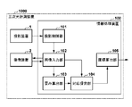
図1は、第1の実施形態の情報処理装置100を備える三次元計測装置1000の構成例を示すブロック図である。投影装置1は、窓形状算出用パターン画像と対応点探索用パターン画像を対象物体に投影する。これらのパターン光は、対象物体の表面で反射し、撮像装置2によって撮像される。撮像装置2が撮像した画像(撮像画像)は、情報処理装置100に送られる。情報処理装置100は、撮像装置2からの撮像画像に基づいて対象物体の三次元座標を算出する。また、情報処理装置100は、投影装置1および撮像装置2の動作を制御する。投影装置1と撮像装置2はお互いの座標系を一致させるための校正が予め行われており、校正データが情報処理装置100内に保存されている。
[Device configuration]
FIG. 1 is a block diagram showing a configuration example of a three-
情報処理装置100は、投影制御部101、画像入力部102、歪み算出部103、対応探索部104、座標算出部105を備える。投影制御部101は、投影装置1を制御し、窓形状算出用パターン画像と対応点探索用パターン画像を順番に投影させるとともに、画像入力部102に制御信号を出力する。画像入力部102は、投影制御部101から入力された制御信号のタイミングに合わせて撮像装置2を制御し、各パターン画像が投影された状態で撮像された撮像画像を受け取る。また、画像入力部102は、窓形状算出用パターン画像が投影された状態で得られた撮像画像を歪み算出部103に出力し、対応点探索用パターン画像が投影された状態で得られた撮像画像を対応探索部104に出力する。
The
歪み算出部103は、窓形状算出用パターン画像と画像入力部102から入力された撮像画像とを比較して撮像画像中の各画素がどのように写像されているか(歪み)を表す歪みパラメタを算出し、対応探索部104に出力する。対応探索部104は、歪み算出部103から入力された歪みパラメタに基づいて画像入力部102から入力された撮像画像に歪みを考慮した窓を生成し、対応点探索用パターン画像と撮像画像との間で対応点探索を行う。対応探索部104は、得られた投影装置1の投影座標と撮像装置2の撮像座標との対応関係を座標算出部105に出力する。座標算出部105は、対応探索部104から入力された投影座標と画像座標の対応関係と、予め求められた投影装置1と撮像装置2の校正データとに基づいて、対象物体の表面の三次元座標を算出する。
The
図12は、図1に示した各機能部を実現する情報処理装置100のハードウエア構成例を示す図である。図12において、CPU161は1つまたは複数のコンピュータ(プロセッサー)を含み、ROM162またはRAM163に格納されたプログラムを実行することで、情報処理装置100の各種処理を実行する。ROM162は読み出し専用の不揮発性メモリであり、RAM163は随時書き込みが可能な揮発性メモリである。RAM163はCPU161の作業メモリとしても機能する。二次記憶装置164は、例えばハードディスクなどで構成される。二次記憶装置164には、プログラム171、パターン画像172、校正データ173が格納されている。プログラム171は、例えば図7のフローチャートにより後述する処理をCPU161に実行させるためのプログラムを含む。パターン画像172は、たとえば、窓形状算出用パターン画像と対応点探索用パターン画像を含む。校正データは、投影装置1と撮像装置2はお互いの座標系を一致させるためのデータである。表示部165は、CPU161の制御下で各種表示を行う。キーボード166、ポインティングデバイス167はユーザからの指示を受け付けるための指示入力部である。インターフェース168は、投影装置1と撮像措置2を情報処理装置100と接続する。上述した各構成は、バス169と接続される。図1に示した各機能部はCPU161がプログラムを実行することにより実現されてもよいし、専用のハードウエアにより実現されてもよい。
FIG. 12 is a diagram showing a hardware configuration example of the
[計測処理]
図7のフローチャートにより第1の実施形態の情報処理装置100による計測処理を説明する。
[Measurement processing]
The measurement process by the
三次元計測装置1000が起動されると、ステップS11において初期化処理が実行される。初期化処理には、投影装置1や撮像装置2の起動、投影装置1と撮像装置2の校正データを作業メモリに読み込む処理、窓形状算出用パターン画像と対応点探索用パターン画像を作業メモリに読み込む処理などが含まれる。
When the three-
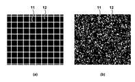
ステップS12では、投影制御部101が、投影装置1に窓形状算出用パターン画像を投影させるとともに、画像入力部102に制御信号を送る。本実施形態で用いられる窓形状算出用パターン画像は、図2(a)に示されるように、正方形が規則的に並んだパターンである。図2(a)において、パターン画像における白部分11は光を投影することを表しており、黒部分12は光を投影しないことを表している。投影制御部101からの制御信号の受信に応じて、画像入力部102は、撮像装置2に撮像を実行させ、撮像画像を入力する。こうして入力された撮像画像は、窓形状算出用パターン画像が投影された状態で撮像された画像である。画像入力部102は、撮像装置2から入力された撮像画像を歪み算出部103に出力する。
In step S12, the
ステップS13では、投影制御部101が、投影装置1に対応点探索用パターン画像を投影させるとともに、画像入力部102に制御信号を送る。本実施形態で用いられる対応点探索用パターン画像は、たとえば、図2(b)に示すように、ドットがランダムに並んだ非周期的な画像である。対応点探索用パターン画像は、同じ特徴を持つ局所領域が一つの探索方向に2つ以上現れない画像であることが望ましい。投影制御部101からの制御信号の受信に応じて、画像入力部102は、撮像装置2に画像を撮像させる。こうして、画像入力部102は、対象物体に対応点探索用パターン画像が投影された状態で撮像された撮像画像を撮像装置2から入力し、対応探索部104に出力する。
In step S13, the
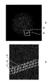
ステップS14では、歪み算出部103が、画像入力部102から入力された撮像画像から窓形状算出用パターン画像における正方形に対応する領域を検出し、検出した領域が正方形と比較してどのように写像されているか(歪み)をパラメタ化する。歪みとは、窓形状算出用パターン画像における局所領域(本例では正方形の領域)が撮像画像中において平行四辺形などに歪むことを指している。例えば、図2(a)に示した窓形状算出用パターン画像を投影装置1により球に投影し、撮像装置2により撮像すると、図3(b)に示すような撮像画像が得られる。この撮像画像を拡大して見ると、図3(a)のようにパターン画像が歪んでいることが分かる。
In step S14, the
このような、撮像画像における、窓形状算出用パターン画像の局所領域に対応する領域の幾何学的な歪みをパラメタ化するため、歪み算出部103は、まず撮像画像(図4(a))から窓形状算出用パターン画像における白線を検出する。例えば、歪み算出部103は、撮像画像の輝度に応じて線上画素(の候補画素)かどうかの二値を判定し、およそ縦方向、横方向に連続する候補画素の集合を縦線、横線として検出する(図4(b)の線21)。そして、歪み算出部103は、隣り合う縦方向の二線と横方向の二線で囲まれる領域を、窓形状算出用パターン画像中の正方領域に対応する領域(図4(c)の領域23)として検出する。例えば、歪み算出部103は、縦線にも横線にも含まれている点を線の交点(図4(b)の交点22)として求め、縦方向、横方向に隣り合う交点が同一の縦線、横線上にあるかどうかを判定する。歪み算出部103は、隣り合う交点が同一の縦線、横線上にあると判定された交点により囲まれた領域を、窓形状算出用パターン画像中の正方形に対応する領域として検出する。
In order to parameterize the geometric distortion of the region corresponding to the local region of the window shape calculation pattern image in the captured image, the
次に、歪み算出部103は、窓形状算出用パターン画像中の正方形に対応する、撮像画像中のすべての領域の歪みをパラメタ化する。パラメタ化する方法は様々ありどのような表現が用いられてもよい。例えば、2次元の線形変換としてパラメタ化する方法が挙げられる。変換前の座標を(u,v)、変換後の座標を(x,y)とすると2次元の線形変換は次の数1に示す式で表わされる。
![]()
![]()
数1において、fは写像を表し、a,b,c,dはfを表現する線形変換を示すパラメタである。窓形状算出用パターン画像中の正方形と撮像画像から検出した領域との対応関係からこれらのパラメタを求める。一つの点(図5における(0,0))を基準とすれば点または線分の対応関係(図5における(0,1)と(x1,y1)、(1,1)と(x2,y2)、(1,0)と(x3,y3))が得られる。この対応関係から解析的にパラメタを求めてもよいし、最小二乗法のような方法で最適なパラメタ求めてもよい。検出した領域内の画素はこのようにして求めたパラメタでパターン画像が歪んでいるものとする。 In Equation 1, f is a parameter representing a mapping, and a, b, c, and d are parameters indicating a linear transformation representing f. These parameters are obtained from the correspondence between the square in the pattern image for window shape calculation and the area detected from the captured image. If one point ((0,0) in FIG. 5) is used as a reference, the correspondence between points or line segments ((0,1) and (x1, y1) in FIG. 5), (1,1) and (x2, y2), (1,0) and (x3, y3)) are obtained. The parameters may be obtained analytically from this correspondence, or the optimum parameters may be obtained by a method such as the least squares method. It is assumed that the pattern image of the pixels in the detected area is distorted by the parameters obtained in this way.
一連の処理を撮像画像中のすべての領域で行うことで、撮像画像の各画素について写像fが決定される。窓形状算出用パターン画像中の正方形に対応する撮像画像中の領域が検出されない、できない領域が発生する場合もあるが、そのような領域では写像fを単位行列としてもよいし、近傍画素における写像fの線形和をとるなどして補間してもよい。歪み算出部103は、求めた歪みパラメタ(画素ごとのf)を対応探索部104に出力する。
By performing a series of processes in all regions in the captured image, the mapping f is determined for each pixel of the captured image. A region in the captured image corresponding to the square in the pattern image for window shape calculation may not be detected or may not be detected. In such a region, the mapping f may be used as an identity matrix, or a mapping in neighboring pixels may occur. Interpolation may be performed by taking a linear sum of f or the like. The
ステップS15では、対応探索部104が、歪み算出部103から入力された歪みパラメタに基づき窓を生成し、対応点探索用パターン画像と画像入力部102から入力された撮像画像との間で対応点探索を行う。対応点探索では、対応点探索用パターン画像と撮像画像との間で注目画素とその近傍画素(例えば、注目画素の周囲8画素)における輝度差などに基づいたコストが条件を満たす(最小、極小など)点をエピポーラ方向に探索し、対応点を求める。一般的には互いに正方形の窓を注目領域としてコストを計算するが、本実施形態ではパターン画像が投影されている画素に対してパターン画像の歪みfを考慮したコスト計算を行い、対応点を探索する。対応点探索用パターン画像の輝度をI、撮像画像の輝度をJ、注目画素をp、注目画素pの近傍画素をq、注目画素pと近傍画素qの集合をWp、注目画素pに対応する画素をr、対応画素rにおける写像をfrとする。対応領域は、対応点探索用パターン画像の投影を含む撮像画像において、対応画素rの周囲に、当該対応画素rについて算出された写像frに基づいて周囲の近傍画素の位置が変換されて配置された領域である。対応領域と注目領域の間のコストを算出するためのコスト関数Cは、例えば次のように設定される。
![]()
![]()
パターン画像の歪み方を考慮した対応点探索の例を図6に示す。図6(a)に示される対応点探索用パターン画像おける白丸31は注目画素p、白枠32は注目画素pとその近傍画素が形成される注目領域(窓)、白線33はエピポーラ線である。図6(b)に示される撮像画像おける白丸34は対応画素rである。白枠35は、対応画素rにおける写像(fr)により示される歪みを考慮した対応領域(窓)であり、対応画素rとその近傍画素で形成される。対応点探索では、エピポーラ線(白線33)に沿って注目画素p(白丸31)を動かし、注目画素pの各位置において注目領域と対応領域とを対比する。注目領域と対応領域について数2のコスト関数により算出されるコストが所定の条件を満たす(最小、極小など)注目画素pを対応点として求める。撮像画像上に歪みを考慮した窓を生成することで、参照画素がサブピクセル値を取る場合があるが、そのような場合にはバイリニア補間をするなどして輝度を求め、コストを計算すればよい。この処理を撮像画像上のすべての画素において行うことで、対応点(pとrのペア)が画素数分だけ得られる。得られたすべての投影座標と撮像座標の対応関係(画素数分のpとrのペア)を座標算出部105に出力する。
FIG. 6 shows an example of a corresponding point search in consideration of how the pattern image is distorted. The
ステップS16では、座標算出部105が、対応探索部104から入力された投影座標と撮像座標との対応関係と予め求められた投影装置1と撮像装置2の校正データから、三角測量を行う。こうして、対象物体の表面の三次元座標(対応点数分の(X,Y,Z)座標)を算出し、処理を終了する。
In step S16, the coordinate
なお、ステップの順は必ずしも図7のフローチャートに示した順である必要はなく、適宜入れ替えてもよいし、並列処理してもよい。 The order of the steps does not necessarily have to be the order shown in the flowchart of FIG. 7, and may be appropriately replaced or parallel processing may be performed.
以上のように、第1の実施形態によれば、投影パターン画像が撮像画像中でどのように歪むかを考慮して窓を生成し、対応点探索を行うことにより、三次元座標を高精度に算出することができる。 As described above, according to the first embodiment, the windows are generated in consideration of how the projection pattern image is distorted in the captured image, and the corresponding point search is performed to obtain the three-dimensional coordinates with high accuracy. Can be calculated in.
[変形例1]
上記実施形態では、ステップS12で窓形状算出用パターン画像を投影し、テップS13において対応点探索用パターン画像を投影し、これらパターン画像の投影を含む撮像画像が別々に取得されるが、これに限られるものではない。たとえば、図8に示すように窓形状算出用パターン画像(図8(a))と対応点探索用パターン画像(図8(b))を混合したパターン画像(図8(c))を投影し、これを撮像して歪みを示すパラメタの取得と対応点の探索に用いるようにしてもよい。あるいは、各パターン画像を投影する光の波長を変え、それら波長に対応した撮像装置を用いることで、これらパターン画像を同時に投影するようにしてもよい。たとえば、第1の波長の光(例えば赤色)で窓形状算出用パターンを投影するとともに、第2の波長の光(例えば緑色)で対応点探索用パターンを投影した状態で、カラー画像の撮像を行う。得られた撮像画像から赤色の線を検出することで歪みを示すパラメタを算出し、緑色の点を検出して探索の対象とする。以上のように、変形例1の構成によれば、一度の投影、撮像で計測が可能となるため、動きのある対象物体であっても、三次元座標を高精度に算出することができる。
[Modification 1]
In the above embodiment, the window shape calculation pattern image is projected in step S12, the corresponding point search pattern image is projected in Tep S13, and the captured images including the projection of these pattern images are separately acquired. It is not limited. For example, as shown in FIG. 8, a pattern image (FIG. 8 (c)) in which a window shape calculation pattern image (FIG. 8 (a)) and a corresponding point search pattern image (FIG. 8 (b)) are mixed is projected. , This may be imaged and used for acquiring a parameter indicating distortion and searching for a corresponding point. Alternatively, by changing the wavelength of the light for projecting each pattern image and using an imaging device corresponding to those wavelengths, these pattern images may be projected at the same time. For example, a color image is captured with the window shape calculation pattern projected by the light of the first wavelength (for example, red) and the corresponding point search pattern projected by the light of the second wavelength (for example, green). Do. A parameter indicating distortion is calculated by detecting a red line from the obtained captured image, and a green point is detected and used as a search target. As described above, according to the configuration of the modified example 1, since the measurement can be performed by one projection and the imaging, the three-dimensional coordinates can be calculated with high accuracy even for a moving target object.
[変形例2]
ステップS12やステップS13において投影されるパターン画像の一例として図2を示したが、パターン画像はこれらに限られるものではない。特に窓形状算出用パターン画像は、図2に示したように既知の幾何形状(正方形)が規則的に並んでいる必要はなく、既知の幾何形状が少なくとも一つ以上あればよい。例えば図9に示すように、異なる種類の既知の幾何形状として正三角形41と正方形42が並んでいるようなパターン画像でもよい。ただし、歪みパラメタを各画素において求めるため、窓形状算出用パターン画像中に既知形状がまんべんなく存在していることが望ましい。
[Modification 2]
FIG. 2 is shown as an example of the pattern image projected in step S12 and step S13, but the pattern image is not limited to these. In particular, in the pattern image for calculating the window shape, it is not necessary for the known geometric shapes (squares) to be regularly arranged as shown in FIG. 2, and it is sufficient that at least one known geometric shape is present. For example, as shown in FIG. 9, a pattern image in which
なお、歪みパラメタを求めるため、撮像画像から既知の幾何形状(以下、既知形状ともにう)を検出する必要がある。例えば、既知形状の検出には、
・撮像画像にSobelフィルタといったエッジ検出フィルタを適用し手エッジを検出し、連結して一周しているエッジを既知形状として検出する方法、
・既知形状をテンプレートとして、LBP(Local Binary Pattern)やSIFT(Scale-Invariant Feature Transform)といった画像特徴量を用いてマッチングを取ることで既知形状を検出する方法、が挙げられる。
In addition, in order to obtain the distortion parameter, it is necessary to detect a known geometric shape (hereinafter, both known shapes) from the captured image. For example, to detect a known shape,
-A method of applying an edge detection filter such as the Sobel filter to the captured image to detect the hand edge, and detecting the connected edge that goes around as a known shape.
-A method of detecting a known shape by matching using an image feature amount such as LBP (Local Binary Pattern) or SIFT (Scale-Invariant Feature Transform) using a known shape as a template can be mentioned.
なお、異なる複数種類の既知形状を、窓形状算出用パターン画像における分割領域に種類ごとに存在させることにより、対応探索部104は、各画素の歪みパラメタとともに各画素がパターン画像中のおよそどの部分と対応しているかを把握できる。例えば、図9の場合、撮像画像中の正三角形41はパターン画像の上部、正方形42はパターン画像の下部と対応している。そのため、対応探索部104は、正三角形41内の画素であれば撮像画像の上部に、正方形42内の画素であれば撮像画像の下部に存在していることを把握できる。その結果、対応探索部104は、たとえば、図6(a)に示した探索範囲をエピポーラ線の上半分などのように限定することができ、三次元座標を高速、高精度に算出することができる。
By allowing a plurality of different types of known shapes to exist in the divided region of the window shape calculation pattern image for each type, the corresponding
[変形例3]
ステップS12やステップS13において、投影するパターン画像は二値に限る必要はなく、階調や色調を持たせたパターン画像でもよい。たとえば、窓形状算出用パターンとして、階調や色調が異なる、既知の幾何形状が並んでいる画像を用いることができる。階調や色調が異なる複数の既知の幾何形状を撮像画像における輝度や色相などを特徴として検出すればよい。このようにすることで、変形例2と同様に、各画素の歪みパラメタとともにパターン画像中のおよそどの部分と対応しているかが分かるため、対応探索部104の探索範囲を限定することができる。したがって、三次元座標を高速、高精度に算出することができる。
[Modification 3]
In step S12 and step S13, the pattern image to be projected does not have to be limited to binary, and may be a pattern image having gradation and color tone. For example, as a window shape calculation pattern, an image in which known geometric shapes having different gradations and color tones are arranged can be used. A plurality of known geometric shapes having different gradations and color tones may be detected as features such as brightness and hue in the captured image. By doing so, it is possible to limit the search range of the
[変形例4]
ステップS15では、ステップS14で求められた歪みパラメタを初期値として、非特許文献1と同様に対応点と窓の歪み方を同時に推定してもよい(数2におけるfrに相当するパラメタも同時に推定する)。すなわち、対応探索部104は、歪み算出部103により算出された写像を初期値として、対応画素rの更新に応じて写像frを更新する。この際、第1の実施形態のように、窓算出用パターン画像の局所領域に対応する、対応点探索用パターン画像の領域内の全探索により写像を探索してもよいし、Graph Cut、Belief Propagation、PatchMatchといったアルゴリズムを用いて写像を探索してもよい。このようにすることで、ある程度正しい歪みパラメタを初期値とすることができるため、写像の探索コストを抑えることができる。したがって、三次元座標を高速、高精度に算出することができる。
[Modification example 4]
In step S15, the strain parameter obtained in step S14 may be used as the initial value, and the corresponding point and the distortion of the window may be estimated at the same time as in Non-Patent Document 1 (the parameter corresponding to fr in
<第2の実施形態>
第1の実施形態では投影装置と撮像装置が1台ずつの構成だったが、第2の実施形態では、対象物体にパターン光を投影し、その反射光を2台の撮像装置によって観測することで対象物体の三次元形状を計測する構成を説明する。第2の実施形態の情報処理装置は、窓形状算出用パターン画像から算出した歪みを考慮した窓を生成し、2台の撮像装置から得られた撮像画像間の対応点探索を行うことで高精度な三次元座標を算出する。2台の撮像装置を用いることで、投影したパターン画像がボケる、相互反射などでパターン画像が崩れる、といった光学的な影響による精度の低下を抑えることができる。
<Second embodiment>
In the first embodiment, the projection device and the image pickup device are configured one by one, but in the second embodiment, the pattern light is projected on the target object and the reflected light is observed by the two image pickup devices. The configuration for measuring the three-dimensional shape of the target object will be described in. The information processing apparatus of the second embodiment generates a window considering the distortion calculated from the pattern image for calculating the window shape, and searches for a corresponding point between the captured images obtained from the two imaging devices. Calculate accurate 3D coordinates. By using two image pickup devices, it is possible to suppress a decrease in accuracy due to optical influences such as the projected pattern image being blurred and the pattern image being distorted due to mutual reflection or the like.
[装置の構成]
図10は、第2の実施形態の情報処理装置100を備える三次元計測装置1000の構成例を示すブロック図である。第1の実施形態とは、撮像装置が1台追加され、第1の撮像装置2と第2の撮像装置3を有している点が異なる。第1の撮像装置2と第2の撮像装置3は、投影装置1によりパターン画像が投影された状態で、異なる位置から撮像を行う。なお、投影装置1、第1の撮像装置2、第2の撮像装置3は各々の座標系を一致させるための校正が予め行われており、校正データが情報処理装置100内に保存されている。なお、情報処理装置100のハードウエア構成は第1の実施形態(図12)と同様である。
[Device configuration]
FIG. 10 is a block diagram showing a configuration example of a three-
情報処理装置100は、投影制御部101、画像入力部102、歪み算出部103、対応探索部104、座標算出部105を備える。投影制御部101は、投影装置1を制御して、窓形状算出用パターン画像と対応点探索用パターン画像を混合したパターン画像(以下、混合パターン画像)を投影させるとともに、画像入力部102に制御信号を出力する。混合パターン画像の一例を図8(c)に示す。なお、第1実施形態と同様に、窓形状算出用パターン画像(図8(a))と対応点探索用パターン画像(図8(b))を順次に個別に投影し、撮像するようにしてもよい。画像入力部102は、投影制御部101から入力された制御信号のタイミングに合わせて、第1の撮像装置2、および、第2の撮像装置3を制御し、撮像を実行させ、それぞれから混合パターン画像が投影された撮像画像を受け取る。画像入力部102は、混合パターン画像が投影された2枚の撮像画像を歪み算出部103に出力する。
The
歪み算出部103は、混合パターン画像内に含まれる窓形状算出用パターン画像と画像入力部102から入力された2枚の撮像画像とに基づいて、それぞれの撮像画像中の各画素がどのように写像されているかを示す歪みパラメタを算出する。歪み算出部103は、算出された2枚の撮像画像の歪みパラメタを対応探索部104に出力する。対応探索部104は、歪み算出部103から入力された歪みパラメタに基づき、歪みを考慮した窓を生成し、画像入力部102から入力された2枚の撮像画像同士の間で対応点探索を行う。対応探索部104は、対応点探索により得られた、第1の撮像装置2の撮像座標と第2の撮像装置3の撮像座標との関係を、座標算出部105に出力する。座標算出部105は、対応探索部104から入力された撮像座標の対応関係と予め求められた第1の撮像装置2と第2の撮像装置3の校正データから、三次元座標を算出する。
The
[計測処理]
図11のフローチャートにより第2の実施形態の情報処理装置100による計測処理を説明する。
[Measurement processing]
The measurement process by the
三次元計測装置2000が起動されると、ステップS21において初期化処理が実行される。初期化処理には、投影装置1、第1の撮像装置2と第2の撮像装置3の起動処理、投影装置1、第1の撮像装置2、および、第2の撮像装置3の校正データを作業メモリに読み込む処理、混合パターン画像を読み込む処理などが含まれる。
When the three-dimensional measuring device 2000 is started, the initialization process is executed in step S21. In the initialization process, the projection device 1, the activation process of the first
ステップS22では、投影制御部101が、投影装置1に混合パターン画像を投影させるとともに、画像入力部102に制御信号を送る。制御信号を受けた画像入力部102は、第1の撮像装置2と第2の撮像装置3に、対象物体に混合パターン画像が投影された画像を撮像させる。画像入力部102は、入力された2枚の撮像画像を歪み算出部103に出力する。
In step S22, the
ステップS23では、歪み算出部103が、画像入力部102から入力された2枚の撮像画像のそれぞれについて、窓形状算出用パターン画像における正方形の領域が、撮像画像へどのように写像されているかを示す歪みパラメタを算出する。歪みパラメタを求める処理は第1の実施形態(S14)と同様である。求めたそれぞれの歪みパラメタ(画素ごとのf)と2枚の撮像画像を対応探索部104に出力する。
In step S23, the
ステップS24では、対応探索部104が、歪み算出部103から入力された歪みパラメタに基づき、2枚の撮像画像のそれぞれにおいて窓を生成し、2枚の撮像画像同士の間で対応点探索を行う。第1の実施形態と同様、対応点探索用パターン画像が投影されている画素に対してパターン画像の歪みfを考慮したコスト計算を行い、対応点を探索する。第1の撮像装置2の撮像画像の輝度をI、第2の撮像装置3の撮像画像の輝度をJ、注目画素をp、注目画素pにおける写像をfp、注目画素pの近傍画素をq(例えば、注目画素pの周囲8画素)、注目画素pと近傍画素qの集合をWpとする。また、注目画素pに対応する画素をr、対応画素rにおける写像をfrとする。例えばコスト関数Cは次の数3により算出される。

コスト関数を用いた対応点探索処理は第1の実施形態と同様である。すなわち、対応探索部104は、エピポーラ線に沿って注目画素を動かし、数3のコスト関数が所定条件を満たす(最小、極小など)注目画素pを求める。このように、2つの撮像画像について対応点の探索を行うと、ボケや相互反射が起きてパターン画像が崩れてしまっても撮像画像同士では同様の見えとなるため、好適に対応点探索を行うことができる。対応探索部104は、得られたすべての撮像座標同士の対応関係(画素数分のpとrのペア)を座標算出部105に出力する。
The corresponding point search process using the cost function is the same as that of the first embodiment. That is, the
ステップS25では、座標算出部105が、対応探索部104から入力された撮像座標同士の対応関係と、第1の撮像装置2と第2の撮像装置3の予め求められた校正データとから、三角測量により三次元座標(対応点数分の(X,Y,Z)座標)を算出する。そして本処理を終了する。
In step S25, the coordinate
以上のように第2の実施形態によれば、投影パターン画像がそれぞれの撮像画像中でどのように歪むかを考慮して窓を生成し、対応点探索がる。また、第2の実施形態によれば、2台の撮像装置を利用することで、ボケや相互反射などの光学的な影響による精度の低下が抑えられるため、三次元座標を高精度に算出することができる。 As described above, according to the second embodiment, a window is generated in consideration of how the projection pattern image is distorted in each captured image, and a corresponding point search is performed. Further, according to the second embodiment, by using two imaging devices, it is possible to suppress a decrease in accuracy due to optical influences such as blurring and mutual reflection, so that the three-dimensional coordinates are calculated with high accuracy. be able to.
[変形例5]
ステップS24において、第1の撮像装置2と第2の撮像装置3の対応関係だけでなく、第1の実施形態のように、投影装置と第1の撮像装置2、投影装置と第2の撮像装置3の対応関係を求めてもよい。このようにすることで、遮蔽などによって三次元座標を計測できない部分を減らすことができる。
[Modification 5]
In step S24, not only the correspondence between the first
[変形例6]
第2の実施形態では投影装置を1台、撮像装置を2台としたが、投影装置および撮像装置の第数はこれに限られるものではなく、投影装置と撮像装置が各々何台あってもよい。ステップS23では、投影装置、撮像装置それぞれペアを決めて歪みを求めればよい。また、ステップS24では、それぞれペアのコストを計算して対応関係を求めてもよいし、Multi-view Stereoのようにすべてのコストを統合して対応関係を求めてもよい。このようにすることで、遮蔽などによって計測できない部分を減らし、より確実に対象物体全体を計測することができる。
[Modification 6]
In the second embodiment, the number of projection devices is one and the number of image pickup devices is two, but the number of projection devices and image pickup devices is not limited to this, and the number of projection devices and image pickup devices is not limited to this. Good. In step S23, the distortion may be obtained by determining a pair of the projection device and the image pickup device. Further, in step S24, the cost of each pair may be calculated to obtain the correspondence relationship, or all the costs may be integrated to obtain the correspondence relationship as in Multi-view Stereo. By doing so, it is possible to reduce the portion that cannot be measured due to shielding or the like, and to measure the entire target object more reliably.
<実施形態の効果>
第1の実施形態によれば、投影パターン画像が撮像画像中でどのように歪むかを考慮して窓を生成し、対応点探索を行うことにより、三次元座標を高精度に算出することができる。
第2の実施形態によれば、第1の実施形態の効果に加え、2台のカメラを利用することで、ボケや相互反射などの光学的な影響による精度の低下を抑えることにより、三次元座標を高精度に算出することができる。
<Effect of embodiment>
According to the first embodiment, it is possible to calculate the three-dimensional coordinates with high accuracy by generating a window in consideration of how the projection pattern image is distorted in the captured image and performing a corresponding point search. it can.
According to the second embodiment, in addition to the effect of the first embodiment, by using two cameras, it is possible to suppress a decrease in accuracy due to optical influences such as blurring and mutual reflection, thereby making it three-dimensional. The coordinates can be calculated with high accuracy.
<定義>
投影制御部101が持つパターン画像は、第1の実施形態や変形例1、2、3で説明したように、歪みを考慮した窓形状を生成し対応点探索を行うことができれば、どのようなパターン画像でもよい。
また、対応探索部104は、第1の実施形態や変形例4で説明したように、対応点を求めることができれば、どのようなアルゴリズムを用いてもよい。
<Definition>
As for the pattern image possessed by the
Further, as described in the first embodiment and the modification 4, the
また、投影装置1や撮像装置2は第2の実施形態や変形例6で説明したように、それぞれ1台に限る必要はなく、複数台あってもよい。
Further, the projection device 1 and the
(その他の実施例)
本発明は、上述の実施形態の1以上の機能を実現するプログラムを、ネットワーク又は記憶媒体を介してシステム又は装置に供給し、そのシステム又は装置のコンピュータにおける1つ以上のプロセッサーがプログラムを読出し実行する処理でも実現可能である。また、1以上の機能を実現する回路(例えば、ASIC)によっても実現可能である。
(Other Examples)
The present invention supplies a program that realizes one or more functions of the above-described embodiment to a system or device via a network or storage medium, and one or more processors in the computer of the system or device reads and executes the program. It is also possible to realize the processing. It can also be realized by a circuit (for example, ASIC) that realizes one or more functions.
1000:三次元計測装置、1:投影装置、2:撮像装置、100:情報処理装置、101:投影制御部、102:画像入力部、103:歪み算出部、104:対応探索部、105:座標算出部 1000: 3D measuring device, 1: Projection device, 2: Imaging device, 100: Information processing device, 101: Projection control unit, 102: Image input unit, 103: Distortion calculation unit, 104: Correspondence search unit, 105: Coordinates Calculation unit
Claims (13)
第2のパターン画像における注目画素とその周囲の近傍画素から構成される注目領域と、前記第2のパターン画像が投影された状態を撮像した撮像画像における領域を前記写像に基づいて変換することにより得られた対応領域と、の対比により、前記第2のパターン画像と前記撮像画像との対応点を探索する探索手段と、を備え、
前記対応領域は、前記第2のパターン画像が投影された状態を撮像した撮像画像における対応画素の周囲に、当該対応画素について前記写像に基づいて前記周囲の近傍画素の位置が変換されて配置された領域であることを特徴とする情報処理装置。 In the captured image in which the first pattern image is captured a state of being projected to have at least one known geometry, the area corresponding to the geometry of the first pattern image, geometry from the geometry A calculation means for calculating a mapping representing a geometrical distortion, and
A region of interest consists of neighboring pixels surrounding the target pixel in the second pattern image by the second pattern image is converted based on the region in the captured image obtained by capturing an image of a state of being projected onto the mapping A search means for searching for a corresponding point between the second pattern image and the captured image by comparison with the obtained corresponding area is provided .
The corresponding region is arranged around the corresponding pixels in the captured image obtained by capturing the projected state of the second pattern image, with the positions of the surrounding neighboring pixels converted for the corresponding pixels based on the mapping. the information processing apparatus according to claim region der Rukoto was.
既知の幾何形状を少なくとも一つ以上有する第1のパターン画像が投影された状態を撮像した撮像画像において、前記第1のパターン画像における前記幾何形状に対応する領域の、前記幾何形状からの幾何学的な歪みを表す写像を算出する工程と、
第2のパターン画像における注目画素とその周囲の近傍画素から構成される注目領域と、前記第2のパターン画像が投影された状態を撮像した撮像画像における領域を前記写像に基づいて変換することにより得られた対応領域と、の対比により、前記第2のパターン画像と前記撮像画像との対応点を探索する探索工程と、を有し、
前記対応領域は、前記第2のパターン画像が投影された状態を撮像した撮像画像における対応画素の周囲に、当該対応画素について前記写像に基づいて前記周囲の近傍画素の位置が変換されて配置された領域であることを特徴とする情報処理装置の制御方法。 It is a control method for information processing equipment.
In the captured image in which the first pattern image is captured a state of being projected to have at least one known geometry, the area corresponding to the geometry of the first pattern image, geometry from the geometry The process of calculating a mapping that represents a geometrical distortion,
A region of interest consists of neighboring pixels surrounding the target pixel in the second pattern image by the second pattern image is converted based on the region in the captured image obtained by capturing an image of a state of being projected onto the mapping the corresponding area obtained by the comparison, have a, a search step of searching corresponding points between the captured image and the second pattern image,
The corresponding region is arranged around the corresponding pixels in the captured image obtained by capturing the projected state of the second pattern image, with the positions of the surrounding neighboring pixels converted for the corresponding pixels based on the mapping. a method of controlling an information processing apparatus characterized by region der Rukoto was.
Priority Applications (1)
| Application Number | Priority Date | Filing Date | Title |
|---|---|---|---|
| JP2016173122A JP6867766B2 (en) | 2016-09-05 | 2016-09-05 | Information processing device and its control method, program |
Applications Claiming Priority (1)
| Application Number | Priority Date | Filing Date | Title |
|---|---|---|---|
| JP2016173122A JP6867766B2 (en) | 2016-09-05 | 2016-09-05 | Information processing device and its control method, program |
Publications (3)
| Publication Number | Publication Date |
|---|---|
| JP2018041169A JP2018041169A (en) | 2018-03-15 |
| JP2018041169A5 JP2018041169A5 (en) | 2019-10-10 |
| JP6867766B2 true JP6867766B2 (en) | 2021-05-12 |
Family
ID=61626128
Family Applications (1)
| Application Number | Title | Priority Date | Filing Date |
|---|---|---|---|
| JP2016173122A Active JP6867766B2 (en) | 2016-09-05 | 2016-09-05 | Information processing device and its control method, program |
Country Status (1)
| Country | Link |
|---|---|
| JP (1) | JP6867766B2 (en) |
Families Citing this family (2)
| Publication number | Priority date | Publication date | Assignee | Title |
|---|---|---|---|---|
| JP7119621B2 (en) * | 2018-06-18 | 2022-08-17 | オムロン株式会社 | Image processing system and image processing method |
| JP2022073496A (en) | 2020-11-02 | 2022-05-17 | セイコーエプソン株式会社 | Determination method for projective transformation matrix, projector, and determination system |
-
2016
- 2016-09-05 JP JP2016173122A patent/JP6867766B2/en active Active
Also Published As
| Publication number | Publication date |
|---|---|
| JP2018041169A (en) | 2018-03-15 |
Similar Documents
| Publication | Publication Date | Title |
|---|---|---|
| JP7282317B2 (en) | Three-dimensional measurement system and three-dimensional measurement method | |
| JP6363863B2 (en) | Information processing apparatus and information processing method | |
| JP4883517B2 (en) | Three-dimensional measuring apparatus, three-dimensional measuring method, and three-dimensional measuring program | |
| JP4885584B2 (en) | Rangefinder calibration method and apparatus | |
| JP6566768B2 (en) | Information processing apparatus, information processing method, and program | |
| US20100328308A1 (en) | Three Dimensional Mesh Modeling | |
| JP6352208B2 (en) | 3D model processing apparatus and camera calibration system | |
| JP2020053008A (en) | Positioning method, robot, and computer storage medium | |
| CN103782232A (en) | Projector and control method thereof | |
| EP2887313B1 (en) | Image processing apparatus, system, image processing method, and computer-readable recording medium | |
| KR20160121509A (en) | Structured light matching of a set of curves from two cameras | |
| JP2012021919A (en) | Image processing system, image processing method and computer program | |
| JP6282377B2 (en) | Three-dimensional shape measurement system and measurement method thereof | |
| JP5624457B2 (en) | Three-dimensional data processing apparatus, method and program | |
| JP6867766B2 (en) | Information processing device and its control method, program | |
| WO2024192102A1 (en) | Systems and methods for splat filling a three-dimensional image using semi-measured data | |
| TWI571099B (en) | Device and method for depth estimation | |
| JP2018009927A (en) | Image processing device, image processing method and program | |
| JP7298687B2 (en) | Object recognition device and object recognition method | |
| JP2015206654A (en) | Information processing apparatus, information processing method, and program | |
| JP6456084B2 (en) | Image processing apparatus, image processing method, and program | |
| JP2017199285A (en) | Information processor, information processing method, program | |
| JP5728399B2 (en) | Measuring device, method and program | |
| JP3823559B2 (en) | How to convert 3D distance data | |
| JP4351090B2 (en) | Image processing apparatus and image processing method |
Legal Events
| Date | Code | Title | Description |
|---|---|---|---|
| A521 | Written amendment |
Free format text: JAPANESE INTERMEDIATE CODE: A523 Effective date: 20190830 |
|
| A621 | Written request for application examination |
Free format text: JAPANESE INTERMEDIATE CODE: A621 Effective date: 20190830 |
|
| A977 | Report on retrieval |
Free format text: JAPANESE INTERMEDIATE CODE: A971007 Effective date: 20200915 |
|
| A131 | Notification of reasons for refusal |
Free format text: JAPANESE INTERMEDIATE CODE: A131 Effective date: 20201009 |
|
| A521 | Written amendment |
Free format text: JAPANESE INTERMEDIATE CODE: A523 Effective date: 20201127 |
|
| RD01 | Notification of change of attorney |
Free format text: JAPANESE INTERMEDIATE CODE: A7421 Effective date: 20210103 |
|
| A521 | Written amendment |
Free format text: JAPANESE INTERMEDIATE CODE: A523 Effective date: 20210113 |
|
| TRDD | Decision of grant or rejection written | ||
| A01 | Written decision to grant a patent or to grant a registration (utility model) |
Free format text: JAPANESE INTERMEDIATE CODE: A01 Effective date: 20210312 |
|
| A61 | First payment of annual fees (during grant procedure) |
Free format text: JAPANESE INTERMEDIATE CODE: A61 Effective date: 20210409 |
|
| R151 | Written notification of patent or utility model registration |
Ref document number: 6867766 Country of ref document: JP Free format text: JAPANESE INTERMEDIATE CODE: R151 |