WO2022201769A1 - 熱伝導部材およびそれを備えるバッテリー - Google Patents
熱伝導部材およびそれを備えるバッテリー Download PDFInfo
- Publication number
- WO2022201769A1 WO2022201769A1 PCT/JP2022/001020 JP2022001020W WO2022201769A1 WO 2022201769 A1 WO2022201769 A1 WO 2022201769A1 JP 2022001020 W JP2022001020 W JP 2022001020W WO 2022201769 A1 WO2022201769 A1 WO 2022201769A1
- Authority
- WO
- WIPO (PCT)
- Prior art keywords
- heat
- elastic sheet
- thickness direction
- conductive film
- film
- Prior art date
- Legal status (The legal status is an assumption and is not a legal conclusion. Google has not performed a legal analysis and makes no representation as to the accuracy of the status listed.)
- Ceased
Links
Images



Classifications
-
- H—ELECTRICITY
- H01—ELECTRIC ELEMENTS
- H01M—PROCESSES OR MEANS, e.g. BATTERIES, FOR THE DIRECT CONVERSION OF CHEMICAL ENERGY INTO ELECTRICAL ENERGY
- H01M10/00—Secondary cells; Manufacture thereof
- H01M10/60—Heating or cooling; Temperature control
- H01M10/61—Types of temperature control
- H01M10/613—Cooling or keeping cold
-
- H—ELECTRICITY
- H01—ELECTRIC ELEMENTS
- H01M—PROCESSES OR MEANS, e.g. BATTERIES, FOR THE DIRECT CONVERSION OF CHEMICAL ENERGY INTO ELECTRICAL ENERGY
- H01M10/00—Secondary cells; Manufacture thereof
- H01M10/60—Heating or cooling; Temperature control
- H01M10/62—Heating or cooling; Temperature control specially adapted for specific applications
- H01M10/625—Vehicles
-
- H—ELECTRICITY
- H01—ELECTRIC ELEMENTS
- H01M—PROCESSES OR MEANS, e.g. BATTERIES, FOR THE DIRECT CONVERSION OF CHEMICAL ENERGY INTO ELECTRICAL ENERGY
- H01M10/00—Secondary cells; Manufacture thereof
- H01M10/60—Heating or cooling; Temperature control
- H01M10/65—Means for temperature control structurally associated with the cells
- H01M10/655—Solid structures for heat exchange or heat conduction
-
- H—ELECTRICITY
- H10—SEMICONDUCTOR DEVICES; ELECTRIC SOLID-STATE DEVICES NOT OTHERWISE PROVIDED FOR
- H10W—GENERIC PACKAGES, INTERCONNECTIONS, CONNECTORS OR OTHER CONSTRUCTIONAL DETAILS OF DEVICES COVERED BY CLASS H10
- H10W40/00—Arrangements for thermal protection or thermal control
- H10W40/10—Arrangements for heating
-
- Y—GENERAL TAGGING OF NEW TECHNOLOGICAL DEVELOPMENTS; GENERAL TAGGING OF CROSS-SECTIONAL TECHNOLOGIES SPANNING OVER SEVERAL SECTIONS OF THE IPC; TECHNICAL SUBJECTS COVERED BY FORMER USPC CROSS-REFERENCE ART COLLECTIONS [XRACs] AND DIGESTS
- Y02—TECHNOLOGIES OR APPLICATIONS FOR MITIGATION OR ADAPTATION AGAINST CLIMATE CHANGE
- Y02E—REDUCTION OF GREENHOUSE GAS [GHG] EMISSIONS, RELATED TO ENERGY GENERATION, TRANSMISSION OR DISTRIBUTION
- Y02E60/00—Enabling technologies; Technologies with a potential or indirect contribution to GHG emissions mitigation
- Y02E60/10—Energy storage using batteries
Definitions
- the present invention relates to a heat conducting member and a battery including the same.
- the circuit board itself is made of a material with excellent heat dissipation properties, a heat sink is attached, or a cooling fan is driven. It is done.
- the method of forming the circuit board itself from a material having excellent heat dissipation properties such as diamond, aluminum nitride (AlN), or cubic boron nitride (cBN)
- the arrangement of the cooling fan causes problems such as the need for maintenance to prevent failures of the fan, which is a rotating device, and the difficulty in securing the installation space.
- heat radiation fins have a large number of pillar-shaped or plate-shaped protruding parts made of a metal with high thermal conductivity (e.g., aluminum). Because it is a flexible member, it is widely used as a heat dissipation component.
- a metal with high thermal conductivity e.g., aluminum
- a heat conduction member for promoting heat dissipation from the heat source described above for example, a member is known in which thin sheets with excellent heat conductivity are alternately exposed in the front and back directions of a resin sheet (Patent See References 1 and 2).
- the conventionally known heat conduction members described above have the following problems.
- a heat conducting member is interposed between the heat source and the cooling member, close contact between the heat conducting member and the heat source or the cooling member is important in order to improve the performance of heat conduction from the heat source to the cooling member.
- there is a risk that a portion of the heat conductive film that forms the path in the thickness direction of the heat conductive member may be deformed irregularly and damaged. This is because the thermal conductive film cannot follow the compression when the thermal conductive member is compressed.
- the shape of the heat conductive film is a shape that resists compression in the thickness direction of the heat conductive member. For this reason, it is still difficult to reduce breakage of the heat conductive film.
- the present invention has been made in view of the problems described above, and aims to reduce breakage of the heat-conducting film that serves as a heat flow path during compression in the thickness direction. Achieving these objectives also contributes to the achievement of the Applicant's Sustainable Development Goal of "ensuring access to affordable, reliable, sustainable and modern energy for all”.
- a heat conduction member according to an embodiment for achieving the above object, A thermally conductive member interposed between a heat source and a cooling member to transfer heat from the heat source to the cooling member, an elastic sheet that is elastically deformable in the thickness direction;
- the heat conduction is provided so as to meander in a predetermined direction in the sheet surface perpendicular to the thickness direction of the elastic sheet while alternately exposed on the front side surface and the back side surface in the thickness direction of the elastic sheet.
- a film; with The heat-conducting film is provided on the elastic sheet so that all or a major portion thereof in the predetermined direction is inclined at an acute angle with respect to the thickness direction in a cross section of the elastic sheet in the thickness direction.
- the heat-conducting film is provided on the elastic sheet so as to be inclined in the same direction with respect to the thickness direction.
- the heat-conducting film is inclined in different directions with respect to the thickness direction with respect to the first position of the elastic sheet in the predetermined direction. It's okay to be (4)
- the heat-conducting film extends toward both ends of the elastic sheet in the predetermined direction and the direction opposite to the predetermined direction with the first position as a boundary. It may be provided so as to gradually decrease the inclination angle with respect to the thickness direction.
- the heat-conducting film extends toward both ends of the elastic sheet in the predetermined direction and the direction opposite to the predetermined direction with the first position as a boundary. It may be provided so as to gradually increase the angle of inclination with respect to the thickness direction.
- the main portion of the heat-conducting film is inclined at an acute angle with respect to the thickness direction in the cross section of the elastic sheet in the thickness direction. is provided on the elastic sheet so as to The thermal conductive film is parallel to the thickness direction at both end regions of the elastic sheet in the predetermined direction and the opposite direction, and is inclined at an acute angle with respect to the thickness direction inside the both end regions.
- the inclination angle of the heat conducting film with respect to the thickness direction may exceed 0 degrees and be 45 degrees or less.
- the heat conductive film may be a carbon film or a carbon-containing resin film.
- the elastic sheet may be a foam sheet.
- the elastic sheet may be a silicone rubber sheet.
- the present invention it is possible to reduce the breakage of the heat conductive film that functions as a heat flow path when the heat conductive member is compressed in the thickness direction.
- FIG. 1 shows a plan view, a right side view and a front view of a heat conducting member according to a first embodiment.
- FIG. 2 shows a cross-sectional view along line AA in FIG. 1 and an enlarged view of a part B thereof before and after compression.
- FIG. 3 shows a cross-sectional view of a plurality of battery cells 30 placed on the surface of the heat-conducting member 1.
- FIG. 4 shows a cross-sectional view of a thermally conductive member according to a second embodiment, a state in which a plurality of battery cells are placed on the thermally conductive member, and a state in which the battery cells expand due to charging and discharging of the battery cells.
- FIG. 4 shows a cross-sectional view of a thermally conductive member according to a second embodiment, a state in which a plurality of battery cells are placed on the thermally conductive member, and a state in which the battery cells expand due to charging and discharging of the battery cells.
- FIG. 5A shows cross-sections in the thickness direction of heat conducting members according to modified examples 1 and 2.
- FIG. 5B shows a cross section in the thickness direction of the heat conducting member according to Modifications 1 and 2.
- FIG. 5C shows a cross section in the thickness direction of the heat conducting member according to Modifications 1 and 2.
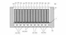
- FIG. 6 shows a longitudinal cross-sectional view of a battery with heat-conducting members.
- FIG. 7 shows a cross-sectional view when the battery cell is placed horizontally so that the side surface of the battery cell is in contact with the heat-conducting member, a partially enlarged view thereof, and a partial cross-sectional view when the battery cell expands during charging and discharging. show.
- Thermally conductive member 10 Elastic sheet 20
- Thermally conductive film 30 31
- Battery cell (an example of heat source) 40 40... Battery , 41 .
- FIG. 1 shows a plan view, a right side view and a front view of a heat conducting member according to a first embodiment.
- FIG. 2 shows a cross-sectional view along line AA in FIG. 1 and an enlarged view of a part B thereof before and after compression.
- the heat conducting member 1 is a member that is interposed between a heat source and a cooling member so that heat can be transferred from the heat source to the cooling member.
- the heat-conducting member 1 is composed of an elastic sheet 10 that is elastically deformable in the thickness direction, and is exposed alternately on the front side surface and the back side surface in the thickness direction of the elastic sheet 10, and is perpendicular to the thickness direction of the elastic sheet 10. and a heat conductive film 20 provided so as to meander and advance in a predetermined direction in the sheet plane.
- the thickness direction of the heat conducting member 1 is the same as the thickness direction of the elastic sheet 10 .
- the elastic sheet 10 is preferably elastically deformable not only in the thickness direction but also in all directions.
- the “predetermined direction” is the lengthwise direction, which is the longest side of the rectangular parallelepiped elastic sheet 10 .
- the "predetermined direction” may be the width direction, which is the second longest direction after the length direction.
- the "predetermined direction” may be a direction along the in-plane outer peripheral edge of the elastic sheet.
- the heat-conducting film 20 is alternately exposed on both sides (the front side and the back side) of the elastic sheet 10 in the thickness direction so as to meander through the elastic sheet 10 .
- the heat-conducting film 20 is formed on the elastic sheet 10 so that all of the above-described predetermined directions are inclined at an acute angle ( ⁇ 1, 0 degrees ⁇ ⁇ 1 ⁇ 90 degrees) with respect to the thickness direction in the cross section of the elastic sheet 10 in the thickness direction. provided for.
- the main portion in the predetermined direction may be used instead of the entire area in the predetermined direction.
- major portion means a portion exceeding 50% of the total.
- cross section means a cross section taken along line AA in FIG. 1 unless otherwise specified.
- Elastic Sheet 10 An important function of the elastic sheet 10 is to provide the thermal conduction member 1 with ease of deformation and resilience. The resilience is due to the elastic deformability of the elastic sheet 10 . Ease of deformation is due to flexibility of the elastic sheet 10 .
- the elastic sheet 10 is preferably a sheet-like member having a function of holding the heat conductive film 20.
- the shape of the elastic sheet 10 is not particularly limited, but is preferably a rectangular parallelepiped shape with a small thickness.
- the elastic sheet 10 in this embodiment has a rectangular parallelepiped shape that is elongated in the order of thickness, width and length.
- the thickness of the elastic sheet 10 is not limited, it preferably has a thickness of 0.2 to 20 mm, more preferably 0.5 to 10 mm.
- the thickness of the elastic sheet 10 is preferably greater than the thickness of the thermal conductive film 20 .
- the elastic sheet 10 preferably holds the heat conductive film 20 by piercing the heat conductive film 20 in the thickness direction and arranging the unevenness repeatedly.
- the elastic sheet 10 holds the heat conductive film 20 so that the heat conductive film 20 is exposed at a predetermined interval on the surface facing the heat source and the surface facing the cooling member (see FIGS. 1 and 2). ).
- the elastic sheet 10 preferably has cuts intermittently in the direction in which the thermally conductive film 20 repeats continuous unevenness (hereinafter also referred to as "predetermined direction"). The cut extends along the width direction of the elastic sheet 10 in this embodiment. The incisions are inclined at an angle of ⁇ 1 with respect to the thickness direction of the elastic sheet 10 .
- the heat-conducting film 20 is provided on the elastic sheet 10 while passing through a plurality of cuts provided in the length direction of the elastic sheet 10 .
- the elastic sheet 10 is preferably made of thermosetting elastomer such as silicone rubber, urethane rubber, isoprene rubber, ethylene propylene rubber, natural rubber, ethylene propylene diene rubber, nitrile rubber (NBR) or styrene butadiene rubber (SBR); , ester-based, styrene-based, olefin-based, butadiene-based, fluorine-based thermoplastic elastomers, or composites thereof. It is preferable that the elastic sheet 10 is made of a material having high heat resistance so as to maintain its shape without being melted or decomposed by the heat transmitted through the heat conductive film 20 .
- thermosetting elastomer such as silicone rubber, urethane rubber, isoprene rubber, ethylene propylene rubber, natural rubber, ethylene propylene diene rubber, nitrile rubber (NBR) or styrene butadiene rubber (SBR); , ester-based,
- the elastic sheet 10 is more preferably made of urethane-based elastomer impregnated with silicone or silicone rubber.
- the elastic sheet 10 is a silicone rubber sheet.
- the elastic sheet 10 may be formed by dispersing fillers such as Al 2 O 3 , AlN, cBN, hBN, and diamond particles in rubber in order to increase its thermal conductivity.
- the elastic sheet 10 is more preferably a highly cushioned sponge containing air bubbles therein.
- elastic sheet 10 is a foam sheet.
- the "elastic sheet” means a member that is highly flexible and elastically deformable so as to be in close contact with the surface of the heat source. can also
- the thermally conductive film 20 is preferably a member having a shape in which continuous unevenness is repeated in a predetermined direction.
- the thermally conductive film 20 has a shape in which continuous unevenness is repeated in the horizontal direction of FIG.
- the heat conductive film 20 is not limited to the horizontal direction in FIG. It can be.
- the thermally conductive film 20 preferably has better thermal conductivity than the elastic sheet 10 .
- the material of the thermally conductive film 20 is not particularly limited, but is preferably a flexible member containing at least one of metal, carbon, or ceramics.
- Thermal conductive film 20 is more preferably a carbon film or a carbon-containing resin film.
- the thermal conductive film 20 is preferably a film composed of 90% by mass or more of carbon.
- the thermal conductive film 20 may be a film containing carbon and resin.
- the resin may be a synthetic fiber, and in that case, an aramid fiber can be preferably used as the resin.
- Carbon as used in the present application is broadly defined to include any structure composed of carbon (element symbol: C) such as graphite, carbon black with lower crystallinity than graphite, diamond, and diamond-like carbon having a structure similar to diamond. is interpreted as
- the thermal conductive film 20 can be a thin film obtained by curing a material in which graphite fibers or carbon particles are blended and dispersed in a resin.
- the thermally conductive film 20 may be carbon fiber woven into a mesh, or may be blended or blended. Various fillers such as graphite fibers, carbon particles, and carbon fibers are all included in the concept of carbon filler. Also, the thermally conductive film 20 may be referred to as a "thermally conductive sheet”.
- the resin may exceed 50% by mass or may be 50% by mass or less of the total mass of the thermally conductive film 20. . That is, it does not matter whether or not the heat conductive film 20 is mainly made of a resin as long as it does not interfere with heat conduction.
- a thermoplastic resin can be preferably used.
- the thermoplastic resin a resin having a high melting point that does not melt when conducting heat from a heat source is preferable.
- Group polyamides (aramid fibers) and the like can be preferably used.
- the resin is dispersed, for example, in the form of particles or fibers in the gaps between the carbon fillers before the heat conductive film 20 is molded.
- the thermally conductive film 20 may have Al 2 O 3 , AlN, or diamond dispersed therein as a filler for further enhancing thermal conductivity, in addition to carbon filler and resin. Further, instead of resin, rubber that is more flexible than resin may be used. Thermally conductive film 20 can also be a film comprising metals and/or ceramics instead of or in combination with carbon as described above. As the metal, a metal having relatively high thermal conductivity such as aluminum, copper, or an alloy containing at least one of them can be selected. As the ceramics, those having relatively high thermal conductivity such as Al 2 O 3 , AlN, cBN and hBN can be selected.
- the heat conductivity of the heat conductive film 20 is preferably 10 W/mK or more.
- the thermally conductive film 20 is preferably a graphite film, which is a material with good thermal and electrical conductivity.
- the heat-conducting film 20 is preferably a film with excellent curvability (or flexibility), and its thickness (t) is not limited, but is preferably 0.02 to 3 mm, more preferably 0.03 to 0.5 mm. more preferred.
- the heat conductive film 20 preferably protrudes from the front side surface and the back side surface of the elastic sheet 10 by at least the thickness t.
- the thickness of the heat conduction member 1 (“initial thickness” or “unpressurized T1 (also referred to as “thickness”) is reduced to T2 ( ⁇ T1).
- the heat conductive film 20 is tilted horizontally (in the direction of the black arrow in FIG. 2), and the initial tilt angle ⁇ 1 changes to increase to ⁇ 2 (> ⁇ 1).
- the heat-conducting film 20 has at least two continuous portions (referred to as “inclined walls 21”) inclined at an angle ⁇ 1 with respect to the thickness direction in a cross section of the elastic sheet 10 cut in the thickness direction. ing.
- the heat conducting film 20 becomes difficult to resist the force. Fall down.
- ⁇ 1 0 degrees
- compression in the thickness direction of the elastic sheet 10 may damage the heat conductive film 10 .
- there are at least two adjacent slanted walls 21 under the condition of 0 degrees ⁇ 1 ⁇ 90 degrees there is room for the slanted walls 21 to further collapse in the horizontal direction in that region. Therefore, the risk of breakage of the heat conductive film 10 can be reduced.
- ⁇ 1 is not particularly limited as long as it is an acute angle, but from the viewpoint of shortening the distance in the elastic sheet 10 and enabling the heat conductive film 20 to be deformed so as to fall down in the horizontal direction, it is preferably 0 degrees ⁇ 1 ⁇ 45 degrees, more preferably 2 degrees ⁇ ⁇ 1 ⁇ 10 degrees.
- the thermally conductive film 20 is provided on the elastic sheet 10 in the same direction with respect to the thickness direction of the elastic sheet 10 and inclined at the same angle ⁇ 1. That is, all the inclined walls 21 are inclined in the same direction and at the same angle ⁇ 1. However, the inclination angles of the inclined walls 21 may not be the same. Moreover, at least two or more adjacent inclined walls 21 need only be continuously inclined in the same direction, and not all the inclined walls 21 need to be inclined in the same direction.
- FIG. 3 shows a state in which a plurality of battery cells 30 are placed on the surface of the heat conducting member 1 in a cross-sectional view.
- the initial thickness T1 of the elastic sheet 10 is reduced to a thickness T2 due to pressure in the thickness direction of the heat-conducting member 1.
- the heat conductive film 20 is deformed so as to fall down in the direction of the white arrow f in FIG.
- the angle ⁇ 1 of the inclined wall 21 becomes larger and changes to the angle ⁇ 2.
- the thermally conductive film 20 can avoid damage due to the room for such deformation.
- the thermally conductive member 1 can be manufactured by molding the thermally conductive film 20, filling the concave portions of the thermally conductive film 20 after the molding with a curable elastic sheet composition, and then curing the composition. Also, two elastic sheet pieces are formed to sandwich the heat conductive film 20 from both sides, and then one heat conductive film 20 is placed between one elastic sheet piece and another elastic sheet piece. It is also possible to complete the thermally conductive member 1 having the unevenly shaped thermally conductive film 20 by sandwiching. Furthermore, after putting the molded thermally conductive film 20 into the mold, a curable elastic sheet composition is supplied into the mold, the composition is cured in the mold, and heat is applied. The conducting member 1 may be manufactured.
- FIG. 4 shows a cross-sectional view of a heat-conducting member according to the second embodiment, a state in which a plurality of battery cells are placed on the heat-conducting member, and a state in which the battery cells expand due to charging and discharging of the battery cells.
- a thermally conductive member 1a according to the second embodiment has a rectangular parallelepiped shape with a small thickness, like the thermally conductive member 1 according to the first embodiment.
- the heat-conducting member 1a differs from the heat-conducting member 1 in that the inclination angle of the inclined wall 21 of the heat-conducting film 20 is set in the predetermined direction in which the heat-conducting film 20 advances (in this embodiment, the length direction of the heat-conducting member 1a). ) are not identical.
- the thermal conductive film 20 is inclined in different directions with respect to the thickness direction of the elastic sheet 10 with respect to the first position (in this embodiment, the central position C in the length direction) of the elastic sheet 10 in a predetermined direction.
- the inclination angle of the inclined wall 21 is .theta.1 on the right side of the center position C
- the inclination angle of the inclined wall 21 on the left side of the center position C is .theta.1' (.noteq..theta.1).
- All of the inclined walls 21 on the right side of the central position C of the heat conductive film 20 are inclined at an acute angle ⁇ 1 clockwise with respect to the thickness direction of the heat conductive member 1a.
- All of the inclined walls 21 on the left side of the central position C of the heat conductive film 20 are inclined counterclockwise at an acute angle ⁇ 1' with respect to the thickness direction of the heat conductive member 1a.
- the thickness of the thermally conductive member 1a is reduced from T1 to T2.
- the heat conductive film 20 is deformed so as to fall in the direction of the white arrow f1, and the angle ⁇ 1 of the inclined wall 21 increases to the angle ⁇ 2.
- the heat conductive film 20 is deformed so as to fall in the direction of the white arrow f2, and the angle ?1' of the inclined wall 21 increases to the angle ?2'.
- ⁇ 1 and ⁇ 1′ are 0 degrees ⁇ 1, ⁇ 1′ ⁇ 45 degrees, more preferably 2 degrees ⁇ 1, ⁇ 1′ ⁇ 10 degrees.
- the central or near central battery cell 30 among the plurality of battery cells 30 tends to overheat. This is because the battery cells 30 that are more difficult to dissipate heat to the surroundings are more likely to overheat.
- a total of 13 battery cells 30 arranged side by side a total of 5 battery cells 30, ie, two battery cells 30 in the center and two on both sides thereof, tend to swell. Due to the expansion of some of these battery cells 30, the laterally-arranged battery cells 30 receive forces in the left and right directions from the central battery cell 30 (see white arrows F1 and F2 in FIG. 4).
- the inclined wall 21 in the heat conductive film 20 on the right side of the central position C changes from the inclination angle ⁇ 2 to ⁇ 3 (> ⁇ 2). Also, the inclined wall 21 of the heat conductive film 20 on the left side of the central position C changes from the inclination angle ⁇ 2' to ⁇ 3' (> ⁇ 2').
- the heat conductive film 20 in the heat conductive member 1a extends from the central position C in the length direction of the heat conductive member 1a toward both sides of the heat conductive member 1a. It is preferable that they are inclined at acute angles in different directions with respect to the thickness direction.
- the thermally conductive film 20 is provided with inclined walls 21 inclined in different directions on both left and right sides of the center position C in the length direction of the thermally conductive member 1a as a starting point.
- the first position which is the starting point, does not necessarily have to be the central position C.
- the thermal conductive film 20 may be provided with inclined walls 21 inclined in different directions on both left and right sides, starting from a position where the length direction of the thermal conductive member 1a is divided into 6:4.
- FIGS. 5A, 5B, and 5C show cross sections in the thickness direction of heat conduction members according to Modifications 1, 2, and 3.
- FIG. 5A, 5B, and 5C show cross sections in the thickness direction of heat conduction members according to Modifications 1, 2, and 3.
- the heat-conducting film 20 extends along the length direction of the elastic sheet 10 (an example of the predetermined direction) and in the opposite direction with respect to the central position C, which is an example of the first position. is provided so that the inclination angle with respect to the thickness direction is gradually reduced toward both ends of the . 5A, 5B, and 5C, dotted lines a through k are drawn along the inclined wall 21.
- the inclination angle with respect to the thickness direction gradually decreases as the dotted lines k, j, i, h, . . . , b move.
- the dotted line a may not be parallel to the thickness direction, but may be an inclined line with a smaller inclination angle than the dotted line b.
- the route of heat inside the heat conducting member 1b also becomes longer, which is a disadvantage in terms of heat conducting efficiency.
- the shape of the heat conductive film 20 is set to the first position (Figs. 5A, 5B, 5C) like the heat conductive member 1b. Then, it is desirable to gradually decrease the inclination angle of the inclined wall 21 from the central position C) of the heat conducting member in the longitudinal direction.
- the heat-conducting film 20 extends in the longitudinal direction (an example of the predetermined direction) of the elastic sheet 10 and in the opposite direction with respect to the central position C, which is an example of the first position. is provided so that the inclination angle with respect to the thickness direction is gradually reduced toward both ends of the .
- the plurality of inclined walls 21 are parallel to the thickness direction. That is, each of the five dotted lines a near both ends in the length direction of the heat conducting member 1c is parallel to the thickness direction.
- the heat-conducting film 20 is provided on the elastic sheet 10 such that the main portion thereof is inclined at an acute angle with respect to the thickness direction of the cross section of the elastic sheet 10 in the thickness direction.
- major portion means the portion greater than 50%.
- the thermal conductive film 20 is parallel to the thickness direction at both end regions of the elastic sheet 10 in a predetermined direction and in the opposite direction (here, the length direction). That is, the heat conductive film 20 is inclined at an acute angle with respect to the thickness direction inside the end regions. Even with the heat-conducting member 1c including such a heat-conducting film 20, the heat-conducting film 20 may be damaged if the force transmitted from the first position to both ends due to the expansion of the battery cells 30 is weak. can be reduced.
- the heat conducting members 1b and 1c give priority to preventing the inclined wall 21 immediately below the first position (here, the central position C) from being damaged, and ensure that the heat source in the region of the first position It is effective when it is necessary to perform heat radiation without any trouble.
- the heat-conducting film 20 has a central position C, which is the first position, in the longitudinal direction (an example of the predetermined direction) of the elastic sheet 10 and both ends in the opposite direction.
- the inclination angle with respect to the thickness direction of the heat conducting member 1d is gradually increased.
- the inclination angle with respect to the thickness direction gradually increases along the dotted lines b, c, d, e, f, g, h, i, and j along each inclined wall 21 .
- the heat-conducting member 1d has inclined walls 21 inclined at an acute angle with respect to the thickness direction of the heat-conducting member 1d even in regions near both ends in the length direction, and parallel to the thickness direction. It does not have a steep sloping wall 21.
- one or two inclined walls 21 parallel to the thickness direction of the heat-conducting member 1d are provided in regions near both ends in the length direction of the heat-conducting member 1d. You can prepare for the above.
- the heat conducting member 1d Starting from the first position (here, the central position C) of the heat conducting member 1d, increasing the inclination angle of the inclined wall 21 toward both ends in the length direction increases This is the same as making the inclination angle of the inclined wall 21 smaller.
- the heat-conducting member 1d is effective when there is a heat source that easily overheats, and priority is given to raising the heat dissipation efficiency by shortening the heat flow path by erecting the inclined wall 21 immediately below as much as possible.
- the prevention of damage to the inclined wall 21 should be prioritized over the improvement of heat dissipation efficiency, so the inclination angle of the inclined wall 21 approaches both ends of the heat conducting member 1d. should be as large as possible.
- the first position is not necessarily limited to the central position C in the length direction of the heat conducting members 1b, 1c, and 1d, and that the angle of inclination from the first position toward both ends is the same as the first position. It is the same as in the second embodiment that the left and right angles in the figure may be the same or different.
- FIG. 6 shows a vertical cross-sectional view of a battery with heat-conducting members.
- the "longitudinal cross-sectional view” means a view cut vertically from the upper opening inside the battery housing to the bottom.
- the heat source is one or two or more battery cells 30.
- a cooling member is a housing 41 containing the battery cells 30 .
- the heat conducting member 1 described above is interposed between the battery cell 30 and the housing 41 .
- the structure of the battery 40 will be described below.
- the battery 40 is, for example, a battery for an electric vehicle and includes a large number of battery cells 30.
- a suitable example of the battery 40 is a lithium ion battery.
- the battery 40 includes a bottomed housing 41 that is open on one side. Housing 41 is preferably made of aluminum or an aluminum-based alloy.
- the battery cell 30 is arranged inside 44 of the housing 41 . Electrodes (not shown) protrude above the battery cells 30 .
- the plurality of battery cells 30 are preferably brought into close contact with each other in the housing 41 by applying force in a compressing direction using screws or the like from both sides thereof (not shown).
- a bottom portion 42 of the housing 41 is provided with one or more water cooling pipes 43 for flowing cooling water 45 .
- the battery cell 30 is arranged in the housing 41 such that the heat conducting member 1 is sandwiched between the bottom portion 42 (an example of the cooling member) that forms part of the housing 41 .
- the battery cells 30 conduct heat to the housing 41 through the heat conducting member 1 and are effectively removed by water cooling.
- the cooling water 45 may be read as a "cooling medium” or a "coolant”.
- An organic solvent such as liquid nitrogen or ethanol may be used instead of the cooling water 45 .
- the heat conducting member 1 is positioned between the battery cells 30 and the bottom portion 42 (part of the housing 41) including the water cooling pipe 43. , are compressed in the thickness direction of the heat-conducting member 1 . As a result, the heat from the battery cells 30 is easily conducted to the heat conductive film 20 , the bottom portion 42 , the water cooling pipe 43 and the cooling water 45 .
- the battery 40 may be provided with the aforementioned heat conducting members 1a, 1b, 1c, and 1d instead of the heat conducting member 1.
- FIG. 7 shows a cross-sectional view when the battery cell is placed horizontally so that the side surface of the battery cell is in contact with the heat-conducting member, a partially enlarged view thereof, and a partial cross-sectional view when the battery cell expands during charging and discharging. show.
- the battery cells 31 may be arranged such that the sides of the battery cells 31 enclosing the battery liquid in the pouch bag are brought into contact with the heat conductive film 20 of the heat conductive member 1 .
- Battery cells 31 increase in temperature during charging and discharging. If the container of the battery cell 31 itself is made of a highly flexible material, the battery cell 31 may swell, especially at the side surfaces thereof. Even in such a case, as shown in FIG.
- the heat conducting member 1 can be deformed according to the shape of the outer surface of the battery cell 31, so that a high heat dissipation can be maintained during charging and discharging. Further, the side surfaces of the battery cells 31 may be brought into contact with the heat conducting members 1a, 1b, 1c, and 1d instead of the heat conducting member 1.
- FIG. 7 the heat conducting member 1 can be deformed according to the shape of the outer surface of the battery cell 31, so that a high heat dissipation can be maintained during charging and discharging. Further, the side surfaces of the battery cells 31 may be brought into contact with the heat conducting members 1a, 1b, 1c, and 1d instead of the heat conducting member 1.
- the thermally conductive members 1, 1a, 1b, 1c, and 1d are manufactured without interposing an adhesive between the thermally conductive film 20 and the elastic sheet 10, for example.
- an adhesive may be interposed between the heat conductive film 20 and the elastic sheet 10 .
- the adhesive may be of any constituent material, but it is preferable to use an adhesive with excellent heat resistance that can withstand at least a temperature rise due to heat radiation from the battery cells 30 and 31 .
- the elastic sheet 10 is not particularly limited in its shape, and at least on the surface facing the battery cells 30 and 31 and the surface facing the bottom 42, the heat conducting film 20 is exposed at a predetermined interval. Any shape that can hold the film 20 may be, for example, elliptical, trapezoidal, circular, polygonal, or the like.
- the inclined wall 21 is a flat plate in each of the above-described embodiments.
- curved plates are also acceptable.
- the inclination angle of the curved inclined plate with respect to the thickness direction of the heat conducting members 1, 1a, 1b, 1c, and 1d is the angle between the surface in contact with the curved vertex and the thickness direction.
- heat sources include not only the battery cells 30 and 31, but also all heat-generating objects such as circuit boards and electronic device bodies.
- the heat source may be electronic components such as capacitors and IC chips.
- the heat conducting members 1, 1a, 1b, 1c, and 1d may be arranged in structures other than the battery 40, such as electronic devices, home appliances, and power generators.
- the heat-conducting member 1a may be configured by joining the lengthwise ends of the two heat-conducting members 1,1.
Landscapes
- Engineering & Computer Science (AREA)
- Manufacturing & Machinery (AREA)
- Chemical & Material Sciences (AREA)
- Chemical Kinetics & Catalysis (AREA)
- Electrochemistry (AREA)
- General Chemical & Material Sciences (AREA)
- Secondary Cells (AREA)
- Battery Mounting, Suspending (AREA)
Abstract
【課題】 熱伝導部材において厚さ方向の圧縮に際して熱流路の役割を成す熱伝導フィルムの破損を低減する。 【解決手段】 本発明は、熱源と冷却部材との間に介在させて熱源から冷却部材へと熱を移動させることのできる熱伝導部材1であって、少なくとも厚さ方向に弾性変形可能な弾性シート10と、弾性シート10の厚さ方向の表側の面と裏側の面に交互に露出しながら弾性シート10の厚さ方向と直角でシート面内の所定方向に蛇行して進行するように備えられる熱伝導フィルム20と、を備え、熱伝導フィルム20は、所定方向の全部若しくは主な部分が弾性シート10の厚さ方向の断面において厚さ方向に対して鋭角に傾斜するように弾性シート10に備えられている熱伝導部材1、およびそれを備えるバッテリーに関する。
Description
本出願は、2021年3月25日に日本国において出願された特願2021-052269に基づき優先権を主張し、当該出願に記載された内容は、本明細書に援用する。また、本願において引用した特許、特許出願及び文献に記載された内容は、本明細書に援用する。
本発明は、熱伝導部材およびそれを備えるバッテリーに関する。
自動車、航空機、船舶あるいは家庭用若しくは業務用電子機器の制御システムは、より高精度かつ複雑化してきており、それに伴って、回路基板上の小型電子部品の集積密度が増加の一途を辿っている。この結果、回路基板周辺の発熱による電子部品の故障や短寿命化を解決することが強く望まれている。
回路基板からの速やかな放熱を実現するには、従来から、回路基板自体を放熱性に優れた材料で構成し、ヒートシンクを取り付け、あるいは冷却ファンを駆動するといった手段を単一で若しくは複数組み合わせて行われている。これらの内、回路基板自体を放熱性に優れた材料、例えばダイヤモンド、窒化アルミニウム(AlN)、立方晶窒化ホウ素(cBN)などから構成する方法は、回路基板のコストを極めて高くしてしまう。また、冷却ファンの配置は、ファンという回転機器の故障、故障防止のためのメンテナンスの必要性や設置スペースの確保が難しいという問題を生じる。これに対して、放熱フィンは、熱伝導性の高い金属(例えば、アルミニウム)を用いた柱状あるいは平板状の突出部位を数多く形成することによって表面積を大きくして放熱性をより高めることのできる簡易な部材であるため、放熱部品として汎用的に用いられている。
ところで、現在、世界中で、地球環境への負荷軽減を目的として、従来からのガソリン車あるいはディーゼル車を徐々に電気自動車に転換しようとする動きが活発化している。特に、フランス、オランダ、ドイツをはじめとする欧州諸国の他、中国でも、電気自動車の普及が進行してきている。電気自動車の普及には、高性能バッテリーの開発の他、多数の充電スタンドの設置などが必要となる。特に、リチウム系の自動車用バッテリーの充放電機能を高めるための技術開発は重要である。上記自動車バッテリーは、摂氏60度以上の高温下では充放電の機能を十分に発揮できないことが良く知られている。また、現在、バッテリーの高速かつ非接触での充電を実現する試験が進行しており、バッテリーの寿命を損なわないように、バッテリーの過充電に伴う発熱への対処も必要になる。このような事情から、先に説明した回路基板と同様、バッテリーにおいても、放熱性を高めることが重要視されている。
上述した熱源からの放熱を促進するための熱伝導部材としては、例えば、熱伝導性に優れる薄いシートを樹脂製のシートの表裏方向に交互に露出させるように備える部材が知られている(特許文献1,2を参照)。
しかし、上記従来から公知の熱伝導部材には次のような課題がある。熱源と冷却部材との間に熱伝導部材を介在させる場合、熱源から冷却部材への熱伝導性能を上げるには、熱伝導部材と熱源あるいは冷却部材との密着が重要である。このため、熱伝導部材の厚さ方向に加圧して熱伝導部材を圧縮するのが好ましい。しかし、熱伝導部材における厚さ方向の経路を構成する熱伝導フィルムの一部が不規則に変形等してしまい破損する危険性がある。これは、熱伝導部材が圧縮される際に、熱伝導フィルムが当該圧縮に追随できないからである。熱伝導フィルムを断面視にて波形としても、あるいは台形と逆台形とを繰り返す形状としても、熱伝導フィルムの形状は、熱伝導部材の厚さ方向の圧縮に抵抗となる形状である。このため、熱伝導フィルムの破損を低減することは依然として難しい。
本発明は、上記のような課題に鑑みてなされたものであり、厚さ方向の圧縮に際して熱流路の役割を成す熱伝導フィルムの破損を低減することを目的とする。このような目的を達成することは、「すべての人々の安価かつ信頼できる持続可能な近代的エネルギーへのアクセスを確保する」という本出願人の持続可能な開発目標の達成にも資する。
(1)上記目的を達成するための一実施形態に係る熱伝導部材は、
熱源と冷却部材との間に介在させて前記熱源から前記冷却部材へと熱を移動させることのできる熱伝導部材であって、
厚さ方向に弾性変形可能な弾性シートと、
前記弾性シートの厚さ方向の表側の面と裏側の面に交互に露出しながら前記弾性シートの前記厚さ方向と直角でシート面内の所定方向に蛇行して進行するように備えられる熱伝導フィルムと、
を備え、
前記熱伝導フィルムは、前記所定方向の全部若しくは主な部分が前記弾性シートの前記厚さ方向の断面において前記厚さ方向に対して鋭角に傾斜するように前記弾性シートに備えられている。
(2)別の実施形態に係る熱伝導部材において、好ましくは、前記熱伝導フィルムは、前記厚さ方向に対して同一方向に傾斜して前記弾性シートに備えられていても良い。
(3)別の実施形態に係る熱伝導部材において、好ましくは、前記熱伝導フィルムは、前記弾性シートの前記所定方向の第1の位置を境に、前記厚さ方向に対して異なる方向に傾斜していても良い。
(4)別の実施形態に係る熱伝導部材において、好ましくは、前記熱伝導フィルムは、前記第1の位置を境に、前記弾性シートの前記所定方向およびその反対方向の両端に向けて、前記厚さ方向に対する傾斜角度を徐々に小さくするように備えられていても良い。
(5)別の実施形態に係る熱伝導部材において、好ましくは、前記熱伝導フィルムは、前記第1の位置を境に、前記弾性シートの前記所定方向およびその反対方向の両端に向けて、前記厚さ方向に対する傾斜角度を徐々に大きくするように備えられていても良い。
(6)別の実施形態に係る熱伝導部材において、好ましくは、前記熱伝導フィルムは、その主な部分が前記弾性シートの前記厚さ方向の断面において前記厚さ方向に対して鋭角に傾斜するように前記弾性シートに備えられており、
前記熱伝導フィルムは、前記弾性シートの前記所定方向およびその反対方向の両端領域にて前記厚さ方向に平行であり、当該両端領域の内側において前記厚さ方向に対して鋭角に傾斜していても良い。
(7)別の実施形態に係る熱伝導部材において、好ましくは、前記熱伝導フィルムの前記厚さ方向に対する傾斜角度は、0度を超えて45度以下であっても良い。
(8)別の実施形態に係る熱伝導部材において、好ましくは、前記熱伝導フィルムは炭素フィルム若しくは炭素含有樹脂フィルムであっても良い。
(9)別の実施形態に係る熱伝導部材において、好ましくは、前記弾性シートは、発泡シートであっても良い。
(10)別の実施形態に係る熱伝導部材において、好ましくは、前記弾性シートは、シリコーンゴムシートであっても良い。
(11)一実施形態に係るバッテリーは、前記熱源は1または2以上のバッテリーセルであり、かつ前記冷却部材は前記バッテリーセルを入れた筐体であり、上述のいずれかの熱伝導フィルムを前記バッテリーセルと前記筐体との間に介在させている。
熱源と冷却部材との間に介在させて前記熱源から前記冷却部材へと熱を移動させることのできる熱伝導部材であって、
厚さ方向に弾性変形可能な弾性シートと、
前記弾性シートの厚さ方向の表側の面と裏側の面に交互に露出しながら前記弾性シートの前記厚さ方向と直角でシート面内の所定方向に蛇行して進行するように備えられる熱伝導フィルムと、
を備え、
前記熱伝導フィルムは、前記所定方向の全部若しくは主な部分が前記弾性シートの前記厚さ方向の断面において前記厚さ方向に対して鋭角に傾斜するように前記弾性シートに備えられている。
(2)別の実施形態に係る熱伝導部材において、好ましくは、前記熱伝導フィルムは、前記厚さ方向に対して同一方向に傾斜して前記弾性シートに備えられていても良い。
(3)別の実施形態に係る熱伝導部材において、好ましくは、前記熱伝導フィルムは、前記弾性シートの前記所定方向の第1の位置を境に、前記厚さ方向に対して異なる方向に傾斜していても良い。
(4)別の実施形態に係る熱伝導部材において、好ましくは、前記熱伝導フィルムは、前記第1の位置を境に、前記弾性シートの前記所定方向およびその反対方向の両端に向けて、前記厚さ方向に対する傾斜角度を徐々に小さくするように備えられていても良い。
(5)別の実施形態に係る熱伝導部材において、好ましくは、前記熱伝導フィルムは、前記第1の位置を境に、前記弾性シートの前記所定方向およびその反対方向の両端に向けて、前記厚さ方向に対する傾斜角度を徐々に大きくするように備えられていても良い。
(6)別の実施形態に係る熱伝導部材において、好ましくは、前記熱伝導フィルムは、その主な部分が前記弾性シートの前記厚さ方向の断面において前記厚さ方向に対して鋭角に傾斜するように前記弾性シートに備えられており、
前記熱伝導フィルムは、前記弾性シートの前記所定方向およびその反対方向の両端領域にて前記厚さ方向に平行であり、当該両端領域の内側において前記厚さ方向に対して鋭角に傾斜していても良い。
(7)別の実施形態に係る熱伝導部材において、好ましくは、前記熱伝導フィルムの前記厚さ方向に対する傾斜角度は、0度を超えて45度以下であっても良い。
(8)別の実施形態に係る熱伝導部材において、好ましくは、前記熱伝導フィルムは炭素フィルム若しくは炭素含有樹脂フィルムであっても良い。
(9)別の実施形態に係る熱伝導部材において、好ましくは、前記弾性シートは、発泡シートであっても良い。
(10)別の実施形態に係る熱伝導部材において、好ましくは、前記弾性シートは、シリコーンゴムシートであっても良い。
(11)一実施形態に係るバッテリーは、前記熱源は1または2以上のバッテリーセルであり、かつ前記冷却部材は前記バッテリーセルを入れた筐体であり、上述のいずれかの熱伝導フィルムを前記バッテリーセルと前記筐体との間に介在させている。
本発明によれば、熱伝導部材において厚さ方向の圧縮に際して熱流路の役割を成す熱伝導フィルムの破損を低減できる。
1,1a,1b,1c,1d・・・熱伝導部材、10・・・弾性シート、20・・・熱伝導フィルム、30,31・・・バッテリーセル(熱源の一例)、40・・・バッテリー、41・・・筐体、42・・・底部(冷却部材の一例)、C・・・中央の位置(第1の位置の一例)、θ1,θ1’・・・傾斜角度。
次に、本発明の各実施形態について、図面を参照して説明する。なお、以下に説明する各実施形態は、特許請求の範囲に係る発明を限定するものではなく、また、各実施形態の中で説明されている諸要素及びその組み合わせの全てが本発明の解決手段に必須であるとは限らない。
<熱伝導部材>
第1実施形態
図1は、第1実施形態に係る熱伝導部材の平面図、右側面図および正面図を示す。図2は、図1におけるA-A線断面図およびその一部Bの圧縮前後の拡大図を示す。
第1実施形態
図1は、第1実施形態に係る熱伝導部材の平面図、右側面図および正面図を示す。図2は、図1におけるA-A線断面図およびその一部Bの圧縮前後の拡大図を示す。
(1)熱伝導部材の概略構成
この実施形態に係る熱伝導部材1は、熱源と冷却部材との間に介在させて、熱源から冷却部材へと熱を移動させることのできる部材である。熱伝導部材1は、厚さ方向に弾性変形可能な弾性シート10と、弾性シート10の厚さ方向の表側の面と裏側の面に交互に露出しながら、弾性シート10の厚さ方向と直角でシート面内の所定方向に蛇行して進行するように備えられる熱伝導フィルム20と、を備える。なお、熱伝導部材1の厚さ方向は、弾性シート10の厚さ方向と同一方向である。弾性シート10は、厚さ方向のみならず、あらゆる方向に弾性変形可能であるのが好ましい。この実施形態では、「所定方向」は、直方体形状の弾性シート10の最長の辺である長さ方向である。ただし、「所定方向」は、長さ方向の次に長い幅方向でも良い。また、楕円柱形状の弾性シートであれば、「所定方向」は、弾性シートの面内の外周縁に沿う方向でも良い。
この実施形態に係る熱伝導部材1は、熱源と冷却部材との間に介在させて、熱源から冷却部材へと熱を移動させることのできる部材である。熱伝導部材1は、厚さ方向に弾性変形可能な弾性シート10と、弾性シート10の厚さ方向の表側の面と裏側の面に交互に露出しながら、弾性シート10の厚さ方向と直角でシート面内の所定方向に蛇行して進行するように備えられる熱伝導フィルム20と、を備える。なお、熱伝導部材1の厚さ方向は、弾性シート10の厚さ方向と同一方向である。弾性シート10は、厚さ方向のみならず、あらゆる方向に弾性変形可能であるのが好ましい。この実施形態では、「所定方向」は、直方体形状の弾性シート10の最長の辺である長さ方向である。ただし、「所定方向」は、長さ方向の次に長い幅方向でも良い。また、楕円柱形状の弾性シートであれば、「所定方向」は、弾性シートの面内の外周縁に沿う方向でも良い。
上述のように、熱伝導フィルム20は、弾性シート10の厚さ方向の両側の面(表側の面と裏側の面)に交互に露出しながら弾性シート10を蛇行パスするように、弾性シート10に備えられている。熱伝導フィルム20は、上述の所定方向の全部が弾性シート10の厚さ方向の断面において当該厚さ方向に対して鋭角(θ1, 0度<θ1<90度)に傾斜するように弾性シート10に備えられている。なお、所定方向の全部に代えて、所定方向の主な部分としても良い。ここで、「主な部分」は、全部に対して50%を超える部分を意味する。以後、「断面」は、特筆しない限り、図1のA-A線断面を意味する。
(2)弾性シート
弾性シート10の重要な機能は、熱伝導部材1に、変形容易性と回復力を付与することである。回復力は、弾性シート10の弾性変形性に起因する。変形容易性は、弾性シート10の柔軟性に起因する。
弾性シート10の重要な機能は、熱伝導部材1に、変形容易性と回復力を付与することである。回復力は、弾性シート10の弾性変形性に起因する。変形容易性は、弾性シート10の柔軟性に起因する。
弾性シート10は、好ましくは、熱伝導フィルム20を保持する機能を有するシート状部材である。弾性シート10の形状は、特に制約はないが、好ましくは、厚さの小さな直方体の形状である。この実施形態における弾性シート10は、厚さ方向、幅方向、長さ方向の順に長い直方体の形状である。弾性シート10は、その厚さに制約はないが、好ましくは0.2~20mm、より好ましくは0.5~10mmの厚さを有する。また、弾性シート10の厚さは、熱伝導フィルム20の厚さより大きいのが好ましい。弾性シート10は、好ましくは、その厚さ方向に熱伝導フィルム20を貫通させて凹凸を繰り返すよう配置させることにより熱伝導フィルム20を保持する。すなわち、弾性シート10は、熱源と対向する面および冷却部材と対向する面において、所定間隔を空けて熱伝導フィルム20が露出するように、熱伝導フィルム20を保持する(図1,2を参照)。弾性シート10は、好ましくは、熱伝導フィルム20が連続した凹凸を繰り返す方向(以後、「所定方向」とも称する。)に向かって、断続的に切り込みを有する。切り込みは、この実施形態では、弾性シート10の幅方向に沿って延びている。切り込みは、弾性シート10の厚さ方向に対してθ1の角度をもって傾斜している。熱伝導フィルム20は、弾性シート10の長さ方向に複数設けられた切り込みを貫通しながら、弾性シート10に備えられている。
弾性シート10は、好ましくは、シリコーンゴム、ウレタンゴム、イソプレンゴム、エチレンプロピレンゴム、天然ゴム、エチレンプロピレンジエンゴム、ニトリルゴム(NBR)あるいはスチレンブタジエンゴム(SBR)等の熱硬化性エラストマー; ウレタン系、エステル系、スチレン系、オレフィン系、ブタジエン系、フッ素系等の熱可塑性エラストマー、あるいはそれらの複合物等を含むように構成される。弾性シート10は、熱伝導フィルム20を伝わる熱によって溶融あるいは分解等せずにその形態を維持できる程度の耐熱性の高い材料から構成されるのが好ましい。この実施形態では、弾性シート10は、より好ましくは、ウレタン系エラストマー中にシリコーンを含浸したもの、あるいはシリコーンゴムにより構成される。この実施形態では、弾性シート10は、シリコーンゴムシートである。弾性シート10は、その熱伝導性を少しでも高めるために、ゴム中にAl2O3、AlN、cBN、hBN、ダイヤモンドの粒子等に代表されるフィラーを分散して構成されていても良い。弾性シート10は、より好ましくは、その内部に気泡を含むクッション性の高いスポンジである。この実施形態では、弾性シート10は、発泡シートである。また、「弾性シート」は、柔軟性に富み、熱源の表面に密着可能に弾性変形可能な部材を意味し、かかる意味では「クッション部材」、「クッションシート」或いは「ゴム状弾性体」と読み替えることもできる。
(2)熱伝導フィルム
熱伝導フィルム20は、好ましくは、所定方向に向かって連続した凹凸を繰り返す形状を有する部材である。この実施形態において、熱伝導フィルム20は、図2の左右方向に向かって連続した凹凸を繰り返す形状を有する。ただし、熱伝導フィルム20は、図2の左右方向に限定されず、紙面奥行方向に向かって連続した凹凸を繰り返す形状であっても良いし、複数の方向に向かって連続した凹凸を繰り返す形状であっても良い。熱伝導フィルム20は、好ましくは、弾性シート10よりも熱伝導性に優れる。熱伝導フィルム20の材料は、特に制約はないが、好ましくは、金属、炭素若しくはセラミックスの少なくとも1つを含み、可撓性を有する部材である。熱伝導フィルム20は、より好ましくは、炭素フィルム若しくは炭素含有樹脂フィルムである。熱伝導フィルム20は、好ましくは、90質量%以上を炭素から構成されるフィルムである。例えば、熱伝導フィルム20に、樹脂を焼成して成るグラファイト製のフィルムを用いることもできる。ただし、熱伝導フィルム20は、炭素と樹脂とを含むフィルムであっても良い。その場合、樹脂は、合成繊維でも良く、その場合には、樹脂として好適にはアラミド繊維を用いることができる。本願でいう「炭素」は、グラファイト、グラファイトより結晶性の低いカーボンブラック、ダイヤモンド、ダイヤモンドに近い構造を持つダイヤモンドライクカーボン等の炭素(元素記号:C)から成る如何なる構造のものも含むように広義に解釈される。熱伝導フィルム20は、この実施形態では、樹脂に、グラファイト繊維やカーボン粒子を配合分散した材料を硬化させた薄いフィルムとすることができる。熱伝導フィルム20は、メッシュ状に編んだカーボンファイバーであっても良く、さらには混紡してあっても混編みしてあっても良い。なお、グラファイト繊維、カーボン粒子あるいはカーボンファイバーといった各種フィラーも、すべて、炭素フィラーの概念に含まれる。また、熱伝導フィルム20は、「熱伝導シート」と称しても良い。
熱伝導フィルム20は、好ましくは、所定方向に向かって連続した凹凸を繰り返す形状を有する部材である。この実施形態において、熱伝導フィルム20は、図2の左右方向に向かって連続した凹凸を繰り返す形状を有する。ただし、熱伝導フィルム20は、図2の左右方向に限定されず、紙面奥行方向に向かって連続した凹凸を繰り返す形状であっても良いし、複数の方向に向かって連続した凹凸を繰り返す形状であっても良い。熱伝導フィルム20は、好ましくは、弾性シート10よりも熱伝導性に優れる。熱伝導フィルム20の材料は、特に制約はないが、好ましくは、金属、炭素若しくはセラミックスの少なくとも1つを含み、可撓性を有する部材である。熱伝導フィルム20は、より好ましくは、炭素フィルム若しくは炭素含有樹脂フィルムである。熱伝導フィルム20は、好ましくは、90質量%以上を炭素から構成されるフィルムである。例えば、熱伝導フィルム20に、樹脂を焼成して成るグラファイト製のフィルムを用いることもできる。ただし、熱伝導フィルム20は、炭素と樹脂とを含むフィルムであっても良い。その場合、樹脂は、合成繊維でも良く、その場合には、樹脂として好適にはアラミド繊維を用いることができる。本願でいう「炭素」は、グラファイト、グラファイトより結晶性の低いカーボンブラック、ダイヤモンド、ダイヤモンドに近い構造を持つダイヤモンドライクカーボン等の炭素(元素記号:C)から成る如何なる構造のものも含むように広義に解釈される。熱伝導フィルム20は、この実施形態では、樹脂に、グラファイト繊維やカーボン粒子を配合分散した材料を硬化させた薄いフィルムとすることができる。熱伝導フィルム20は、メッシュ状に編んだカーボンファイバーであっても良く、さらには混紡してあっても混編みしてあっても良い。なお、グラファイト繊維、カーボン粒子あるいはカーボンファイバーといった各種フィラーも、すべて、炭素フィラーの概念に含まれる。また、熱伝導フィルム20は、「熱伝導シート」と称しても良い。
熱伝導フィルム20を炭素と樹脂とを備えるフィルムとする場合には、当該樹脂が熱伝導フィルム20の全質量に対して50質量%を超えていても、あるいは50質量%以下であっても良い。すなわち、熱伝導フィルム20は、熱伝導に大きな支障が無い限り、樹脂を主材とするか否かを問わない。樹脂としては、例えば、熱可塑性樹脂を好適に使用できる。熱可塑性樹脂としては、熱源からの熱を伝導する際に溶融しない程度の高融点を備える樹脂が好ましく、例えば、ポリフェニレンスルフィド(PPS)、ポリエーテルエーテルケトン(PEEK)、ポリアミドイミド(PAI)、芳香族ポリアミド(アラミド繊維)等を好適に挙げることができる。樹脂は、熱伝導フィルム20の成形前の状態において、炭素フィラーの隙間に、例えば粒子状あるいは繊維状に分散している。熱伝導フィルム20は、炭素フィラー、樹脂の他、熱伝導をより高めるためのフィラーとして、Al2O3、AlNあるいはダイヤモンドを分散していても良い。また、樹脂に代えて、樹脂よりも柔軟なゴムを用いても良い。熱伝導フィルム20は、また、上述のような炭素に代えて若しくは炭素と共に、金属および/またはセラミックスを含むフィルムとすることができる。金属としては、アルミニウム、銅、それらの内の少なくとも1つを含む合金などの熱伝導性の比較的高いものを選択できる。また、セラミックスとしては、Al2O3、AlN、cBN、hBNなどの熱伝導性の比較的高いものを選択できる。
熱伝導フィルム20は、導電性に優れるか否かは問わない。熱伝導フィルム20の熱伝導率は、好ましくは10W/mK以上である。この実施形態では、熱伝導フィルム20は、好ましくは、グラファイト製のフィルムであり、熱伝導性と導電性に優れる材料から成る。熱伝導フィルム20は、湾曲性(若しくは屈曲性)に優れるフィルムであるのが好ましく、その厚さ(t)に制約はないが、0.02~3mmが好ましく、0.03~0.5mmがより好ましい。熱伝導フィルム20は、好ましくは、弾性シート10の表側の面および裏側の面から少なくとも厚さtの分だけ突出している。
図2に示すように、熱伝導部材1の厚さ方向に重みWを付与すると(図2の白矢印方向を参照)、熱伝導部材1の厚さ(「初期厚さ」あるいは「無加圧時厚さ」ともいう)T1は、T2(<T1)に減る。この際、熱伝導フィルム20は、水平方向(図2の黒矢印方向)に倒れこみ、初期の傾斜角度θ1がθ2(>θ1)に大きくなるように変化する。熱伝導フィルム20は、弾性シート10の厚さ方向に切断したときの断面において、厚さ方向に対して角度θ1傾斜している部位(「傾斜壁21」という)を少なくとも2つ連続して備えている。このため、熱伝導部材1の厚さ方向に力が加わった際に、熱伝導フィルム20は、その力に抵抗困難となり、弾性シート10の厚さ方向の圧縮に伴い角度θ1を大きくするように倒れこむ。θ1=0度の場合には、弾性シート10の厚さ方向の圧縮によって、熱伝導フィルム10が破損する可能性がある。しかし、0度<θ1<90度の条件で、少なくとも2つの隣り合う傾斜壁21が存在すると、その領域にて傾斜壁21がさらに水平方向に向けて倒れこむように変形できる余地がある。このため、熱伝導フィルム10の破損リスクを低減可能である。θ1は、鋭角であれば特に制約はないが、弾性シート10内の距離を短くでき、かつ熱伝導フィルム20が水平方向に倒れこむように変形できるようにする観点では、好ましくは0度<θ1≦45度、より好ましくは2度≦θ1≦10度である。この実施形態では、熱伝導フィルム20は、弾性シート10の厚さ方向に対して同一方向で、かつ同一角度θ1で傾斜して弾性シート10に備えられている。すなわち、全ての傾斜壁21は、同一方向で、かつ同一角度θ1で傾斜している。しかし、傾斜壁21の傾斜角度は同一でなくとも良い。また、少なくとも2以上の隣り合う傾斜壁21が連続して同一方向に傾斜していれば良く、全ての傾斜壁21が同一方向に傾斜していなくとも良い。
図3は、複数個のバッテリーセル30を熱伝導部材1の面上に載せた状況を断面視にて示す。
熱伝導部材1の最も広に面に複数個のバッテリーセル30を載せると、熱伝導部材1の厚さ方向への加圧によって、弾性シート10の初期厚さT1が厚さT2へと小さくなる。この際に、熱伝導フィルム20には、図3の白矢印fの方向に倒れこむように変形する。この結果、傾斜壁21の角度θ1は、より大きくなり、角度θ2へと変化する。熱伝導フィルム20は、このような変形の余地があることによって、破損を免れることが可能となる。
熱伝導部材1の製造方法としては、公知の製法を利用できる。例えば、熱伝導フィルム20を成形し、当該成形後の熱伝導フィルム20の凹部に硬化性弾性シート組成物を満たしてから当該組成物を硬化させて熱伝導部材1を製造可能である。また、熱伝導フィルム20の両側から挟むための弾性シート断片を2つ成形し、続いて、1つの弾性シート断片と、もう1つの弾性シート断片との間に、1枚の熱伝導フィルム20を挟んで、凹凸形状の熱伝導フィルム20を備えた熱伝導部材1を完成することもできる。さらには、金型内に、成形済みの熱伝導フィルム20を入れた後、同金型内に、硬化性弾性シート組成物を供給し、金型内にて当該組成物を硬化させて、熱伝導部材1を製造しても良い。
第2実施形態
次に、第2実施形態に係る熱伝導部材について説明する。先の実施形態と共通する部分については同じ符号を付して重複した説明を省略する。
次に、第2実施形態に係る熱伝導部材について説明する。先の実施形態と共通する部分については同じ符号を付して重複した説明を省略する。
図4は、第2実施形態に係る熱伝導部材、当該熱伝導部材に複数のバッテリーセルを載せた状態およびバッテリーセルの充放電によってバッテリーセルが膨張したときの状態を断面視にて示す。
第2実施形態に係る熱伝導部材1aは、第1実施形態に係る熱伝導部材1と同様、厚さの小さい直方体の形状を有する。しかし、熱伝導部材1aは、熱伝導部材1と異なり、熱伝導フィルム20の傾斜壁21の傾斜角度は、熱伝導フィルム20が進行する所定方向(この実施形態では熱伝導部材1aの長さ方向)において同一ではない。熱伝導フィルム20は、弾性シート10の所定方向の第1の位置(この実施形態では、長さ方向の中央の位置C)を境に、弾性シート10の厚さ方向に対して異なる方向に傾斜している。また、図4中、中央の位置Cより右側では、傾斜壁21の傾斜角度はθ1であり、中央の位置Cより左側では、傾斜壁21の傾斜角度はθ1’(≠θ1)である。熱伝導フィルム20の中央の位置Cより右側の傾斜壁21は、全て、熱伝導部材1aの厚さ方向に対して時計回りに鋭角でθ1傾いている。熱伝導フィルム20の中央の位置Cより左側の傾斜壁21は、全て、熱伝導部材1aの厚さ方向に対して反時計回りに鋭角でθ1’傾いている。
かかる形態の熱伝導部材1aの最も広い面に複数のバッテリーセル30を載せると、熱伝導部材1aの厚さはT1からT2に縮まる。熱伝導フィルム20は、中央の位置Cより右側では、白矢印f1の方向に倒れこむように変形して、傾斜壁21の角度θ1は角度θ2へと大きくなる。また、熱伝導フィルム20は、中央の位置Cより左側では、白矢印f2の方向に倒れこむように変形して、傾斜壁21の角度θ1’は角度θ2’へと大きくなる。なお、この実施形態では、0度<θ1<θ2<90度および0度<θ1’<θ2’<90度である。また、θ1およびθ1’は、0度<θ1,θ1’≦45度、より好ましくは2度≦θ1,θ1’≦10度である。
複数のバッテリーセル30が充放電時に膨張すると、複数のバッテリーセル30の内の中央または中央に近いバッテリーセル30が過熱しやすい。これは、周囲への放熱が困難なバッテリーセル30ほど過熱しやすいからである。この実施形態では、横並びの合計13個のバッテリーセル30の内、中央及びその両隣2個ずつの合計5個のバッテリーセル30が膨張しやすい。これら一部のバッテリーセル30の膨張によって、横並びのバッテリーセル30は、中央のバッテリーセル30から左右の方向に力を受ける(図4中の白矢印F1,F2を参照)。中央の位置Cより右側の熱伝導フィルム20における傾斜壁21は、傾斜角度θ2からθ3(>θ2)へと変化する。また、中央の位置Cより左側の熱伝導フィルム20における傾斜壁21は、傾斜角度θ2’からθ3’(>θ2’)へと変化する。このように、バッテリーセル30の膨張現象を考慮すると、熱伝導部材1a中の熱伝導フィルム20は、熱伝導部材1aの長さ方向の中央の位置Cから両側に向かって、熱伝導部材1aの厚さ方向に対して異なる方向に鋭角傾斜している方が好ましい。
この実施形態では、θ1とθ1’とは異なる角度であるが、同一角度であっても良い。また、この実施形態では、熱伝導フィルム20は、熱伝導部材1aの長さ方向の中央の位置Cを起点として、その左右両側に異なる方向に傾斜する傾斜壁21を備える。しかし、起点となる第1の位置は、必ずしも中央の位置Cでなくとも良い。例えば、熱伝導フィルム20は、熱伝導部材1aの長さ方向を6:4に分ける位置を起点として、その左右両側に異なる方向に傾斜する傾斜壁21を備えても良い。
各種変形例
次に、熱伝導部材の一部変形例について説明する。かかる変形例において先の各実施形態と共通する部分については同じ符号を付して重複した説明を省略する。
次に、熱伝導部材の一部変形例について説明する。かかる変形例において先の各実施形態と共通する部分については同じ符号を付して重複した説明を省略する。
図5A,図5B,図5Cは、変形例1,2,3に係る熱伝導部材の厚さ方向の断面を示す。
変形例1に係る熱伝導部材1bでは、熱伝導フィルム20は、第1の位置の一例である中央の位置Cを境に、弾性シート10の長さ方向(所定方向の一例)およびその反対方向の両端に向けて、厚さ方向に対する傾斜角度を徐々に小さくするように備えられている。図5A,図5B,図5Cでは、傾斜壁21に沿って点線a~kが描かれている。熱伝導部材1bの長さ方向の両末端では、傾斜壁21は、厚さ方向と平行であり傾斜していない。すなわち、点線aは、厚さ方向と平行である。点線k、j、i、h、・・・、bに移行するに従い、厚さ方向に対する傾斜角度は徐々に小さくなっている。なお、点線aは、厚さ方向と平行ではなく、点線bよりも傾斜角度が小さい傾斜線でも良い。
図4を参照して説明したように、第1の位置に近いバッテリーセル30の膨張に起因して、その周囲のバッテリーセル30群にF1,F2の力が加わると、両端に近づくほど、力が弱くなる。このため、両端に近い傾斜壁21ほど厚さ方向に平行であっても破損の危険性が低いと考えられる。逆に、第1の位置に近い傾斜壁21には、両端に比べて大きな力が加わり破損する危険性が高くなる。このような現象を考慮すると、第1の位置から両端に向かって傾斜角度を少しずつ小さくするのが好ましい。全ての傾斜壁21の角度を厚さ方向に対して大きく一律にする方法も考えられる。しかし、その場合には、熱伝導部材1b内部における熱のルートも長くなり、熱伝導効率の面ではマイナスになる。熱伝導フィルム20の破損の低リスク化と高熱伝導効率の両立を図る観点では、熱伝導部材1bのように、熱伝導フィルム20の形状を、第1の位置(図5A,図5B,図5Cでは、熱伝導部材の長さ方向の中央の位置C)を境に傾斜壁21の傾斜角度を徐々に小さくしていくようにするのが望ましい。
変形例2に係る熱伝導部材1cでは、熱伝導フィルム20は、第1の位置の一例である中央の位置Cを境に、弾性シート10の長さ方向(所定方向の一例)およびその反対方向の両端に向けて、厚さ方向に対する傾斜角度を徐々に小さくするように備えられている。ただし、熱伝導部材1cの長さ方向の両端に近い領域では、複数の傾斜壁21は厚さ方向に平行となっている。すなわち、熱伝導部材1cの長さ方向の両端に近い各5本の点線aは、厚さ方向と平行である。点線k、j、i、h、g,fに移行するに従い、厚さ方向に対する傾斜角度は徐々に小さくなっている。変形例2では、熱伝導フィルム20は、その主な部分が弾性シート10の厚さ方向の断面において当該厚さ方向に対して鋭角に傾斜するように前記弾性シートに備えられている。ここで、「主な部分」は、50%を超える部分を意味する。熱伝導フィルム20は、弾性シート10の所定方向およびその反対方向(ここでは長さ方向)の両端領域にて厚さ方向に平行である。すなわち、熱伝導フィルム20は、当該両端領域の内側において厚さ方向に対して鋭角に傾斜している。このような熱伝導フィルム20を備える熱伝導部材1cであっても、バッテリーセル30の膨張に伴う第1の位置から両端側への力の伝達が弱い場合には、熱伝導フィルム20の破損を低減できる。
熱伝導部材1b,1cは、第1の位置(ここでは、中央の位置C)の直下の傾斜壁21の破損を防止することを優先し、確実に第1の位置の領域にある熱源からの放熱を支障なく行わせる必要がある場合に有効である。
変形例3に係る熱伝導部材1dでは、熱伝導フィルム20は、第1の位置である中央の位置Cを境に、弾性シート10の長さ方向(所定方向の一例)およびその反対方向の両端に向けて、熱伝導部材1dの厚さ方向に対する傾斜角度を徐々に大きくするように備えられている。各傾斜壁21に沿う点線b、c、d、e、f、g、h、i、jに移行するに従い、厚さ方向に対する傾斜角度は徐々に大きくなっている。熱伝導部材1dは、熱伝導部材1cと異なり、長さ方向の両端に近い領域でも傾斜壁21を熱伝導部材1dの厚さ方向に対して鋭角に傾斜しており、当該厚さ方向と平行な傾斜壁21を備えていない。ただし、熱伝導部材1dにおいて、熱伝導部材1b,1cと同様、熱伝導部材1dの長さ方向の両端に近い領域で、熱伝導部材1dの厚さ方向に平行な傾斜壁21を1または2以上備えても良い。熱伝導部材1dの第1の位置(ここでは、中央の位置C)を起点として、長さ方向の両端に向かって傾斜壁21の傾斜角度を大きくすることは、中央の位置Cに近い位置の傾斜壁21の傾斜角度ほど小さくすることと同じ意味である。このように傾斜壁21を形成すると、中央の位置Cに近い熱源からの熱流路を短くでき、効果的な放熱を実行できる。熱伝導部材1dは、過熱しやすい熱源が存在する場合に、その直下の傾斜壁21をできるだけ立てて熱流路を短くすることで放熱効率を上げることを優先する場合に有効である。過熱しやすい熱源以外の熱源のある領域では、放熱効率を上げることよりも傾斜壁21の破損を防止することを優先すれば良いので、傾斜壁21の傾斜角度は熱伝導部材1dの両端に近づくほど大きくすれば良い。
なお、第1の位置は、熱伝導部材1b,1c,1dの長さ方向の中央の位置Cに必ずしも限定されないこと、および第1の位置から両端に向かって傾斜する角度は、第1の位置から図中の左右同一角度であってもまたは異なる角度であっても良いことは、第2実施形態と同様である。
<バッテリー>
次に、本実施形態に係るバッテリーについて説明する。
次に、本実施形態に係るバッテリーについて説明する。
図6は、熱伝導部材を備えるバッテリーの縦断面図を示す。ここで、「縦断面図」は、バッテリーの筐体内部の上方開口面から底部へと垂直に切断する図を意味する。
この実施形態に係るバッテリー40において、熱源は1または2以上のバッテリーセル30である。また、冷却部材はバッテリーセル30を入れた筐体41である。前述の熱伝導部材1は、バッテリーセル30と筐体41との間に介在している。以下、バッテリー40の構造について説明する。
この実施形態において、バッテリー40は、例えば、電気自動車用のバッテリーであって、多数のバッテリーセル30を備える。バッテリー40の好適な例としては、リチウムイオンバッテリーを挙げることができる。バッテリー40は、一方に開口する有底型の筐体41を備える。筐体41は、好ましくは、アルミニウム若しくはアルミニウム基合金から成る。バッテリーセル30は、筐体41の内部44に配置される。バッテリーセル30の上方には、電極(不図示)が突出して設けられている。複数のバッテリーセル30は、好ましくは、筐体41内において、その両側からネジ等を利用して圧縮する方向に力を与えられて、互いに密着するようになっている(不図示)。筐体41の底部42には、冷却水45を流すために、1または複数の水冷パイプ43が備えられている。バッテリーセル30は、筐体41の一部を構成する底部42(冷却部材の一例)との間に、熱伝導部材1を挟むようにして、筐体41内に配置される。
上記構造のバッテリー40では、バッテリーセル30は、熱伝導部材1を通じて筐体41に伝熱して、水冷によって効果的に除熱される。なお、冷却水45は、「冷却媒体」あるいは「冷却剤」と読み替えても良い。冷却水45に代えて、液体窒素、エタノール等の有機溶剤を用いても良い。
バッテリーセル30を筐体41内にセットした状態では(図6を参照)、熱伝導部材1は、バッテリーセル30と、水冷パイプ43を備える底部42(筐体41の一部)との間において、熱伝導部材1の厚さ方向に圧縮される。この結果、バッテリーセル30からの熱は、熱伝導フィルム20、底部42、水冷パイプ43、冷却水45へと伝わりやすくなる。バッテリー40は、熱伝導部材1に代えて、先述の熱伝導部材1a,1b,1c,1dを備えていても良い。
図7は、熱伝導部材の上に、バッテリーセルの側面を接触させるように横置きにしたときの断面図、その一部拡大図および充放電時にバッテリーセルが膨張した際の一部断面図を示す。
先述の実施形態では、バッテリーセル30を縦にしてその下端に熱伝導部材1を接触せしめている状況について説明したが、バッテリーセルの構造および配置の形態は、これに限定されない。図7に示すように、パウチ袋内にバッテリー液を封入したバッテリーセル31の側面を熱伝導部材1の熱伝導フィルム20に接触させるように、バッテリーセル31を配置しても良い。バッテリーセル31は、充電および放電の際に温度上昇する。バッテリーセル31の容器自体が柔軟性に富む材料にて形成されていると、バッテリーセル31の特に側面が膨らむ可能性がある。そのような場合でも、図7に示すように、熱伝導部材1がバッテリーセル31の外面の形状に合わせて変形できるので、充放電時にも放熱性を高く維持できる。また、熱伝導部材1に代えて、熱伝導部材1a,1b,1c,1dにバッテリーセル31の側面を接触させても良い。
<その他実施形態>
上述のように、本発明の好適な各実施形態について説明したが、本発明は、これらに限定されることなく、種々変形して実施可能である。
上述のように、本発明の好適な各実施形態について説明したが、本発明は、これらに限定されることなく、種々変形して実施可能である。
また、熱伝導部材1,1a,1b,1c,1dは、熱伝導フィルム20と弾性シート10との間に、例えば接着剤を介在させずに製造されている。しかし、熱伝導フィルム20と弾性シート10との間に接着剤が介在していても良い。接着剤は、その構成材料を問わないが、少なくともバッテリーセル30,31からの放熱による温度上昇に耐え得るような耐熱性に優れた接着剤を用いることが好ましい。
また、弾性シート10は、その形状に特に制約はなく、少なくともバッテリーセル30,31と対向する面および底部42と対向する面において、所定間隔を空けて熱伝導フィルム20が露出するように熱伝導フィルム20を保持可能な形状であれば、例えば、楕円、台形、円、多角形状等であっても良い。
傾斜壁21は、上述の各実施形態では平板である。しかし、湾曲した板でも良い。その場合、湾曲した傾斜板の熱伝導部材1,1a,1b,1c,1dの厚さ方向に対する傾斜角度は、湾曲した頂点に接する面と上記厚さ方向との角度となる。
また、熱源は、バッテリーセル30,31のみならず、回路基板や電子機器本体などの熱を発する対象物を全て含む。例えば、熱源は、キャパシタおよびICチップ等の電子部品であっても良い。また、熱伝導部材1、1a,1b,1c,1dは、バッテリー40以外の構造物、例えば、電子機器、家電、発電装置等に配置されていても良い。
また、上述の各実施形態の複数の構成要素は、互いに組み合わせ不可能な場合を除いて、自由に組み合わせ可能である。熱伝導部材1aは、2つの熱伝導部材1,1の長さ方向の端部を合わせて構成されていても良い。
Claims (11)
- 熱源と冷却部材との間に介在させて前記熱源から前記冷却部材へと熱を移動させることのできる熱伝導部材であって、
少なくとも厚さ方向に弾性変形可能な弾性シートと、
前記弾性シートの厚さ方向の表側の面と裏側の面に交互に露出しながら前記弾性シートの前記厚さ方向と直角でシート面内の所定方向に蛇行して進行するように備えられる熱伝導フィルムと、
を備え、
前記熱伝導フィルムは、前記所定方向の全部若しくは主な部分が前記弾性シートの前記厚さ方向の断面において前記厚さ方向に対して鋭角に傾斜するように前記弾性シートに備えられていることを特徴とする熱伝導部材。 - 前記熱伝導フィルムは、前記弾性シートの前記厚さ方向に対して同一方向に傾斜して前記弾性シートに備えられていることを特徴とする請求項1に記載の熱伝導部材。
- 前記熱伝導フィルムは、前記弾性シートの前記所定方向の第1の位置を境に、前記弾性シートの前記厚さ方向に対して異なる方向に傾斜していることを特徴とする請求項1に記載の熱伝導部材。
- 前記熱伝導フィルムは、前記第1の位置を境に、前記弾性シートの前記所定方向およびその反対方向の両端に向けて、前記厚さ方向に対する傾斜角度を徐々に小さくするように備えられていることを特徴とする請求項3に記載の熱伝導部材。
- 前記熱伝導フィルムは、前記第1の位置を境に、前記弾性シートの前記所定方向およびその反対方向の両端に向けて、前記厚さ方向に対する傾斜角度を徐々に大きくするように備えられていることを特徴とする請求項3に記載の熱伝導部材。
- 前記熱伝導フィルムは、その主な部分が前記弾性シートの前記厚さ方向の断面において前記厚さ方向に対して鋭角に傾斜するように前記弾性シートに備えられており、
前記熱伝導フィルムは、前記弾性シートの前記所定方向およびその反対方向の両端領域にて前記厚さ方向に平行であり、当該両端領域の内側において前記厚さ方向に対して鋭角に傾斜していることを特徴とする請求項1から5のいずれか1項に記載の熱伝導部材。 - 前記熱伝導フィルムが前記弾性シートの前記厚さ方向に対する傾斜角度は、0度を超えて45度以下であることを特徴とする請求項1から6のいずれか1項に記載の熱伝導部材。
- 前記熱伝導フィルムは炭素フィルム若しくは炭素含有樹脂フィルムであることを特徴とする請求項1から7のいずれか1項に記載の熱伝導部材。
- 前記弾性シートは、発泡シートであることを特徴とする請求項1から8のいずれか1項に記載の熱伝導部材。
- 前記弾性シートは、シリコーンゴムシートであることを特徴とする請求項1から9のいずれか1項に記載の熱伝導部材。
- 前記熱源は1または2以上のバッテリーセルであり、かつ前記冷却部材は前記バッテリーセルを入れた筐体であり、請求項1から10のいずれか1項に記載の熱伝導部材を前記バッテリーセルと前記筐体との間に介在させていることを特徴とするバッテリー。
Priority Applications (1)
| Application Number | Priority Date | Filing Date | Title |
|---|---|---|---|
| JP2023508666A JP7542131B2 (ja) | 2021-03-25 | 2022-01-14 | 熱伝導部材およびそれを備えるバッテリー |
Applications Claiming Priority (2)
| Application Number | Priority Date | Filing Date | Title |
|---|---|---|---|
| JP2021-052269 | 2021-03-25 | ||
| JP2021052269 | 2021-03-25 |
Publications (1)
| Publication Number | Publication Date |
|---|---|
| WO2022201769A1 true WO2022201769A1 (ja) | 2022-09-29 |
Family
ID=83396752
Family Applications (1)
| Application Number | Title | Priority Date | Filing Date |
|---|---|---|---|
| PCT/JP2022/001020 Ceased WO2022201769A1 (ja) | 2021-03-25 | 2022-01-14 | 熱伝導部材およびそれを備えるバッテリー |
Country Status (2)
| Country | Link |
|---|---|
| JP (1) | JP7542131B2 (ja) |
| WO (1) | WO2022201769A1 (ja) |
Cited By (1)
| Publication number | Priority date | Publication date | Assignee | Title |
|---|---|---|---|---|
| WO2025107844A1 (zh) * | 2023-11-20 | 2025-05-30 | 宁德时代新能源科技股份有限公司 | 热管理部件、电池以及用电装置 |
Citations (5)
| Publication number | Priority date | Publication date | Assignee | Title |
|---|---|---|---|---|
| WO2007125802A1 (ja) * | 2006-04-24 | 2007-11-08 | Sumitomo Electric Industries, Ltd. | 熱伝達部材、凸状構造部材、電子機器、および電気製品 |
| JP2012031242A (ja) * | 2010-07-29 | 2012-02-16 | Nitto Denko Corp | 熱伝導性シート |
| JP2015201534A (ja) * | 2014-04-08 | 2015-11-12 | パナソニックIpマネジメント株式会社 | 熱伝導シートおよびその製造方法 |
| JP2016192520A (ja) * | 2015-03-31 | 2016-11-10 | 太陽誘電株式会社 | 蓄電モジュール |
| JP2019207759A (ja) * | 2018-05-28 | 2019-12-05 | 信越ポリマー株式会社 | 放熱構造体およびバッテリー |
-
2022
- 2022-01-14 JP JP2023508666A patent/JP7542131B2/ja active Active
- 2022-01-14 WO PCT/JP2022/001020 patent/WO2022201769A1/ja not_active Ceased
Patent Citations (5)
| Publication number | Priority date | Publication date | Assignee | Title |
|---|---|---|---|---|
| WO2007125802A1 (ja) * | 2006-04-24 | 2007-11-08 | Sumitomo Electric Industries, Ltd. | 熱伝達部材、凸状構造部材、電子機器、および電気製品 |
| JP2012031242A (ja) * | 2010-07-29 | 2012-02-16 | Nitto Denko Corp | 熱伝導性シート |
| JP2015201534A (ja) * | 2014-04-08 | 2015-11-12 | パナソニックIpマネジメント株式会社 | 熱伝導シートおよびその製造方法 |
| JP2016192520A (ja) * | 2015-03-31 | 2016-11-10 | 太陽誘電株式会社 | 蓄電モジュール |
| JP2019207759A (ja) * | 2018-05-28 | 2019-12-05 | 信越ポリマー株式会社 | 放熱構造体およびバッテリー |
Cited By (1)
| Publication number | Priority date | Publication date | Assignee | Title |
|---|---|---|---|---|
| WO2025107844A1 (zh) * | 2023-11-20 | 2025-05-30 | 宁德时代新能源科技股份有限公司 | 热管理部件、电池以及用电装置 |
Also Published As
| Publication number | Publication date |
|---|---|
| JPWO2022201769A1 (ja) | 2022-09-29 |
| JP7542131B2 (ja) | 2024-08-29 |
Similar Documents
| Publication | Publication Date | Title |
|---|---|---|
| JP7190311B2 (ja) | 放熱構造体およびバッテリー | |
| CN213071222U (zh) | 散热结构体及安装有该散热结构体的蓄电池 | |
| US11495842B2 (en) | Heat dissipating structure and battery provided with the same | |
| CN115398716B (zh) | 散热结构体及具备该散热结构体的电池 | |
| JP7503432B2 (ja) | 放熱構造体およびそれを備えるバッテリー | |
| JP6886543B1 (ja) | 放熱構造体およびそれを備えるバッテリー | |
| TW202030906A (zh) | 散熱結構體以及具備該散熱結構體的電池 | |
| JP2019207759A (ja) | 放熱構造体およびバッテリー | |
| JP2020113387A (ja) | 放熱構造体およびそれを備えるバッテリー | |
| JPWO2019244882A1 (ja) | 放熱構造体、放熱構造体の製造方法およびバッテリー | |
| WO2022201769A1 (ja) | 熱伝導部材およびそれを備えるバッテリー | |
| JP2022175357A (ja) | 熱伝導部材およびそれを備えるバッテリー | |
| JP2021153005A (ja) | 放熱構造体およびバッテリー | |
| JPWO2019230107A1 (ja) | 放熱構造体およびバッテリー | |
| JP7376568B2 (ja) | 放熱構造体シートおよび放熱構造体の製造方法 | |
| JP2021197295A (ja) | 放熱構造体、バッテリーおよび電子機器 | |
| JP7573483B2 (ja) | 熱伝導部材およびそれを備えるバッテリー | |
| JP7534878B2 (ja) | デバイス | |
| JP7598454B2 (ja) | 熱伝導部材、熱伝導部材の製造方法およびバッテリー | |
| WO2023157236A1 (ja) | 熱伝導部材及びその製造方法、並びにバッテリー | |
| JP2021125409A (ja) | 熱伝導構造体およびそれを備えるバッテリー | |
| JP2020009579A (ja) | 放熱構造体およびバッテリー | |
| JP7550092B2 (ja) | 熱伝導ユニットおよびそれを備えるバッテリー | |
| JP2021005582A (ja) | 放熱構造体およびそれを備えるバッテリー | |
| JP2022165443A (ja) | バッテリー |
Legal Events
| Date | Code | Title | Description |
|---|---|---|---|
| 121 | Ep: the epo has been informed by wipo that ep was designated in this application |
Ref document number: 22774574 Country of ref document: EP Kind code of ref document: A1 |
|
| WWE | Wipo information: entry into national phase |
Ref document number: 2023508666 Country of ref document: JP |
|
| NENP | Non-entry into the national phase |
Ref country code: DE |
|
| 122 | Ep: pct application non-entry in european phase |
Ref document number: 22774574 Country of ref document: EP Kind code of ref document: A1 |