WO2022201742A1 - 回転電機 - Google Patents
回転電機 Download PDFInfo
- Publication number
- WO2022201742A1 WO2022201742A1 PCT/JP2022/000360 JP2022000360W WO2022201742A1 WO 2022201742 A1 WO2022201742 A1 WO 2022201742A1 JP 2022000360 W JP2022000360 W JP 2022000360W WO 2022201742 A1 WO2022201742 A1 WO 2022201742A1
- Authority
- WO
- WIPO (PCT)
- Prior art keywords
- oil passage
- oil
- rotor shaft
- axial
- discharge hole
- Prior art date
- Legal status (The legal status is an assumption and is not a legal conclusion. Google has not performed a legal analysis and makes no representation as to the accuracy of the status listed.)
- Ceased
Links
Images



Classifications
-
- H—ELECTRICITY
- H02—GENERATION; CONVERSION OR DISTRIBUTION OF ELECTRIC POWER
- H02K—DYNAMO-ELECTRIC MACHINES
- H02K9/00—Arrangements for cooling or ventilating
- H02K9/19—Arrangements for cooling or ventilating for machines with closed casing and closed-circuit cooling using a liquid cooling medium, e.g. oil
Definitions
- the present disclosure relates to rotating electric machines.
- a tubular oil passage forming member is attached to a cylindrical projecting portion of a cover member that covers one axial end side of the rotary electric machine, and the oil passage forming member extends into the hollow interior of the rotor shaft, thereby forming an oil passage of the oil passage forming member. It is known to supply oil into the rotor shaft via The oil supplied to the hollow interior of the rotor shaft is supplied to each of the coil end portions on both sides in the axial direction after being distributed within the hollow interior of the rotor shaft.
- the oil is supplied to the hollow interior of the rotor shaft, it is distributed to each of the coil end portions on both sides in the axial direction within the rotor shaft.
- the oil is supplied from the oil passage of the oil passage forming member to the vicinity of the axial center of the rotor shaft. , the axial length of the oil passage forming member tends to be relatively long.
- an object of the present disclosure is to realize distribution of oil to different positions in the axial direction at the stage of supplying oil from the oil passage of the oil passage forming member to the hollow inside of the rotor shaft.
- a stator having stator coils; a rotor having a hollow rotor shaft and a rotor core fixed to the outer peripheral surface of the rotor shaft; an oil passage forming member extending from an axial opening on one axial end side of the rotor shaft into a hollow interior of the rotor shaft to form an oil passage;
- the oil passage is A first oil passage extending along the axial direction with a center axis vertically above the axial center of the rotor shaft and capable of discharging oil toward a first position on the inner peripheral surface of the rotor shaft.
- a second oil passage capable of discharging oil toward a second position closer to the one end side in the axial direction than the first position on the inner peripheral surface of the rotor shaft.
- FIG. 1 is a skeleton diagram of a vehicle drive system including a rotating electric machine
- FIG. FIG. 2 is a cross-sectional view schematically showing a main part of a rotating electric machine
- FIG. 10 is a plan view showing part of the cover member viewed from the X1 side along the X direction
- FIG. 3 is an enlarged view of a Q1 portion of FIG. 2
- FIG. 3 is an enlarged view of a Q2 portion of FIG. 2
- FIG. 6 is an enlarged view of a Q3 portion of FIG. 5; It is explanatory drawing of a modification.
- FIG. 1 is a skeleton diagram of a vehicle drive system 100 including a rotating electrical machine 1. As shown in FIG. In FIG. 1, an X direction and X1 and X2 sides along the X direction are defined. The X direction is parallel to the direction of the first axis A1 (hereinafter also referred to as "axial direction").
- the vehicle drive system 100 includes a rotating electrical machine 1 that serves as a drive source for wheels W, and a power transmission mechanism 7 that is provided in a power transmission path connecting the rotating electrical machine 1 and the wheels W.
- the power transmission mechanism 7 includes an input member 3, a counter gear mechanism 4, a differential gear mechanism 5, and left and right output members 6A and 6B.
- the input member 3 has an input shaft 31 and an input gear 32 .
- the input shaft 31 is a rotating member that rotates around the first axis A1.
- the input gear 32 is a gear that transmits rotational torque (driving force) from the rotary electric machine 1 to the counter gear mechanism 4 .
- the input gear 32 is provided on the input shaft 31 of the input member 3 so as to rotate together with the input shaft 31 of the input member 3 .
- the counter gear mechanism 4 is arranged between the input member 3 and the differential gear mechanism 5 in the power transmission path.
- the counter gear mechanism 4 has a counter shaft 41 , a first counter gear 42 and a second counter gear 43 .
- the counter shaft 41 is a rotating member that rotates around the second axis A2.
- the second axis A2 extends parallel to the first axis A1.
- the first counter gear 42 is an input element of the counter gear mechanism 4 .
- the first counter gear 42 meshes with the input gear 32 of the input member 3 .
- the first counter gear 42 is connected to the counter shaft 41 so as to rotate together with the counter shaft 41 .
- the second counter gear 43 is an output element of the counter gear mechanism 4.
- the second counter gear 43 is formed to have a smaller diameter than the first counter gear 42 .
- the second counter gear 43 is provided on the counter shaft 41 so as to rotate together with the counter shaft 41 .
- the differential gear mechanism 5 is arranged on the third axis A3 as its rotation axis.
- a third axis A3 extends parallel to the first axis A1.
- the differential gear mechanism 5 distributes the driving force transmitted from the rotary electric machine 1 side to the left and right output members 6A and 6B.
- the differential gear mechanism 5 has a differential input gear 51 that meshes with the second counter gear 43 of the counter gear mechanism 4 .
- the differential gear mechanism 5 also includes a differential case 52, in which a pinion shaft, pinion gears, left and right side gears, and the like are accommodated.
- the left and right side gears are connected to the left and right output members 6A, 6B so as to rotate together.
- the left and right output members 6A, 6B are drivingly connected to the left and right wheels W, respectively.
- the left and right output members 6A and 6B transmit the driving force distributed by the differential gear mechanism 5 to the wheels W, respectively.
- the left and right output members 6A and 6B may be composed of two or more members.
- the rotating electric machine 1 drives the wheels W via the power transmission mechanism 7.
- the vehicle drive system 100 may be configured without the power transmission mechanism 7 .
- other power transmission mechanisms such as planetary gear trains may be utilized.
- FIG. 2 is a cross-sectional view schematically showing a main part of the rotating electrical machine 1.
- FIG. 3 is a plan view showing part of the cover member viewed from the X1 side along the X direction.
- FIG. 4 is an enlarged view of the Q1 portion of FIG.
- the Z direction is a direction perpendicular to the axial direction and corresponds to the vertical direction.
- the Z1 side is the upper side and the Z2 side is the lower side.
- the Z direction need not be strictly parallel to the direction of gravity, and may be slightly inclined with respect to the direction of gravity.
- the rotating electric machine 1 has a rotor 310 and a stator 320 inside the case 2 .
- the case 2 may be made of, for example, aluminum.
- the case 2 can be formed by casting or the like.
- Case 2 includes a motor case 250 and a cover member 252 .
- Case 2 accommodates rotating electric machine 1 .
- the case 2 may further accommodate the power transmission mechanism 7 as schematically shown in FIG.
- the motor case 250 forms a motor housing chamber SP1 that houses the rotating electric machine 1.
- the motor housing chamber SP1 may be an oil-tight space containing oil for cooling and/or lubricating the rotating electric machine 1 (and/or the power transmission mechanism 7).
- the motor case 250 has a peripheral wall portion that surrounds the radially outer side of the rotary electric machine 1 .
- Motor case 250 may be realized by combining a plurality of members. Further, the motor case 250 may be integrated with another case member 254 that forms the gear housing chamber SP2 that houses the power transmission mechanism 7 on the X direction X1 side.
- the cover member 252 is coupled to the motor case 250 on the X direction X2 side.
- the cover member 252 is in the form of a cover that covers the X-direction X2 side of the motor accommodation chamber SP1.
- the cover member 252 may cover the opening of the motor case 250 on the X direction X2 side in such a manner as to completely or substantially completely close it.
- a part of the motor accommodation chamber SP1 may be formed by the cover member 252 .
- a bearing 240 that rotatably supports the rotor 310 is provided on the cover member 252 . That is, the cover member 252 has a bearing support portion 2524 that supports the bearing 240 .
- the bearing 240 is provided radially outward at the end of the rotor shaft 314 on the X2 side, as shown in FIG. Specifically, the bearing 240 is supported by the cover member 252 at the radially outer side of the outer race, and is supported by the outer peripheral surface of the rotor shaft 314 at the radially inner side of the inner race. In a modified example, the bearing 240 may be supported by the cover member 252 at the radially inner side of the inner race and supported by the inner peripheral surface of the rotor shaft 314 at the radially outer side of the outer race.
- the cover member 252 includes a circular bottom portion 2521 centered on the first axis A1, and a peripheral wall portion 2522 projecting from the outer peripheral edge of the bottom portion 2521 toward the X direction X1 side. , the end surface of the peripheral wall portion 2522 on the X direction X1 side is coupled to the motor case 250 .
- a cylindrical bearing support portion 2524 protruding in the X direction X1 is formed in the center portion (the portion centered on the first axis A1) of the bottom portion 2521 on the X direction X1 side. Note that the bearing support portion 2524 is formed concentrically around the first axis A1.
- an axially protruding portion is provided radially inward of the cylindrical bearing support portion 2524. 2525 are formed.
- the axial projecting portion 2525 is formed in a central portion (a portion around the first axis A1) on the X direction X1 side of the bottom portion 2521 in a manner projecting in the X direction X1 side.
- the rotor 310 has a rotor core 312 and a rotor shaft 314 .
- the rotor core 312 may be made of, for example, an annular magnetic layered steel plate. Permanent magnets (not shown) may be embedded inside the rotor core 312 . Alternatively, permanent magnets (not shown) may be attached to the outer peripheral surface of rotor core 312 . Arrangement of permanent magnets (not shown) is optional. Rotor core 312 is fixed to the outer peripheral surface of rotor shaft 314 and rotates together with rotor shaft 314 .
- the rotor shaft 314 defines the first axis A1, which is the rotation axis of the rotating electric machine 1.
- Rotor shaft 314 is rotatably supported by cover member 252 of case 2 via bearing 240 on the X2 side of the portion where rotor core 312 is fixed.
- the rotor shaft 314 is rotatably supported by the case 2 via a bearing 241 on the other axial end side (X1 side) of the rotary electric machine 1 . In this manner, the rotor shaft 314 may be rotatably supported by the case 2 at both ends in the axial direction.
- the rotor shaft 314 is connected to the input shaft 31 on the X direction X1 side so as to be able to transmit power.
- a spline 61 is formed on the inner peripheral surface of the rotor shaft 314 and is spline-fitted so as to mesh with a spline 62 formed on the outer peripheral surface of the input shaft 31 .
- the rotor shaft 314 is for example in the form of a hollow tube and has a hollow interior 314A. Hollow interior 314 A may extend the full axial length of rotor shaft 314 .
- the inner peripheral surface of the rotor shaft 314 has a constant inner diameter except for the section where the splines 61 are formed.
- the rotor shaft 314 may be configured to have a reduced diameter at both axial ends or one end, in which case the inner peripheral surface of the rotor shaft 314 may be reduced at both axial ends or one end. inner diameter.
- a hollow interior 314A of the rotor shaft 314 functions as an axial oil passage 83. That is, oil is supplied to the hollow interior 314A via a cover oil passage 80, which will be described later. As a result, the rotor shaft 314 is cooled, so that the rotor core 312 (and the permanent magnets, if provided) can be cooled from the radially inner side.
- a weir portion 89 for oil reservoir may be formed in the hollow interior 314A of the rotor shaft 314 .
- the rotor shaft 314 may have a weir portion 89 protruding radially inward along the entire circumference on the inner peripheral surface.
- the dam portion 89 is formed by an annular plug that fits into the hollow interior 314A of the rotor shaft 314. As shown in FIG.
- the rotor shaft 314 is formed with a radial third oil passage 831A and a fourth oil passage 831B for discharging oil to the coil end portions 322A and 322B of the stator 320, respectively.
- the third oil passage 831A has an opening facing the coil end portion 322A in the radial direction, and supplies oil in the axial oil passage 83 toward the coil end portion 322A.
- the third oil passage 831A linearly extends parallel to the radial direction, but may linearly extend in an oblique direction that is slightly inclined with respect to the radial direction.
- the fourth oil passage 831B has an opening facing the coil end portion 322B in the radial direction, and supplies oil in the axial oil passage 83 toward the coil end portion 322B.
- the fourth oil passage 831B linearly extends parallel to the radial direction, but may linearly extend in an oblique direction that is slightly inclined with respect to the radial direction.
- the stator 320 includes a stator core 321 and stator coils 322 .
- the stator core 321 may be made of, for example, an annular magnetic layered steel plate. Teeth (not shown) protruding radially inward are radially formed on the inner peripheral portion of the stator core 321 .
- the stator coil 322 may be in the form of, for example, a conductor having a rectangular cross section or a circular cross section with an insulating coating. Stator coil 322 is wound around teeth (not shown) of stator core 321 . It should be noted that the stator coils 322 may be electrically connected by Y-connection or by ⁇ -connection in a parallel relationship of one or more, for example.
- the stator coil 322 has coil end portions 322A and 322B which are portions protruding axially outward from the slots of the stator core 321 .
- the coil end portion 322A is located on the X1 side, and the coil end portion 322B is located on the X2 side.
- the cover member 252 is formed with a cover oil passage 80, a first oil passage 81, and a second oil passage 82.
- the number of parts can be reduced compared to the case where the first oil passage 81 and the second oil passage 82 are formed of tubular members separate from the cover member 252, for example.
- the cover oil passage 80 is formed in the bottom portion 2521 of the cover member 252 .
- the cover oil passage 80 is formed in the cover oil passage 80 so as to pass through the first axis A1 or its vicinity.
- the cover oil passage 80 may have any form as long as it communicates with the first oil passage 81, which will be described later.
- the cover oil passage 80 may be a simple space, or may be provided with fins or the like.
- the cover oil passage 80 may have a section that circles around the first axis A1, or may circle around the first axis A1 while moving back and forth in the radial direction.
- the cover oil passage 80 may be formed with a cooling water passage. In this case, the oil in the cover oil passage 80 may be cooled by the cooling water flowing in the cooling water passage.
- the cover oil passage 80 communicates with the discharge side of an oil pump (not shown). In this case, oil discharged from the oil pump is supplied to the cover oil passage 80 .
- the oil pump may be of a mechanical type or may be of an electric type driven by an electric motor.
- the first oil passage 81 extends linearly in the axial direction.
- the first oil passage 81 has a central axis I1 that is offset upward with respect to the first axis A1, as shown in FIG.
- the cross-sectional shape of the first oil passage 81 (the cross-sectional shape when cut along a plane perpendicular to the central axis I1) may be circular.
- the central axis I1 of the first oil passage 81 may be defined by a set of centroids of the cross-sectional shape.
- the first oil passage 81 is formed in the axial projection 2525 of the cover member 252 .
- the first oil passage 81 is formed along the entire axial direction of the axial protrusion 2525 . 2 and 4, when the axial dimension of the bottom portion 2521 of the cover member 252 is relatively large, the end portion of the first oil passage 81 on the X direction X2 side is formed on the bottom portion 2521. good too.
- the first oil passage 81 communicates with the cover oil passage 80 at the end on the X direction X2 side and opens on the X direction X1 side.
- the first oil passage 81 extends to the hollow inside 314A of the rotor shaft 314 on the X direction X1 side. Therefore, the axial protrusion 2525 extends into the hollow interior 314A of the rotor shaft 314 on the X direction X1 side, as shown in FIGS.
- the first oil passage 81 has an axial discharge hole 811 at the end on the X1 side. Oil is supplied to the first oil passage 81 from the cover oil passage 80, and the oil supplied to the first oil passage 81 is injected (discharged) from the discharge hole 811 in the X direction X1.
- the discharge mode of the oil from the first oil passage 81 is schematically shown by an arrow R21.
- the oil discharged from the discharge hole 811 of the first oil passage 81 is supplied to the third oil passage 831A (the coil end portion 322A on the X-direction X1 side) in a relatively axial direction. It is ejected to fly over a long distance.
- the landing position P1 of the oil discharged from the discharge hole 811 of the first oil passage 81 is preferably closer to the midpoint position P0 between the third oil passage 831A and the fourth oil passage 831B in the axial direction. , near the third oil passage 831A.
- the landing position P1 of the oil discharged from the discharge hole 811 of the first oil passage 81 is the position on the surface of the hollow interior 314A of the rotor shaft 314 (that is, the inner peripheral surface of the rotor shaft 314). Note that the landing position P1 of the oil discharged from the discharge hole 811 of the first oil passage 81 changes according to the discharge pressure of the oil from the oil pump.
- the maximum value of the oil discharge pressure (the maximum value of the actual change range) may be used as a reference. This also applies to the landing position P2, which will be described later.
- the oil discharged from the discharge hole 811 of the first oil passage 81 is on the front side of the third oil passage 831A on the surface of the hollow interior 314A (that is, the inner peripheral surface of the rotor shaft 314). It lands on the front side (X2 side when viewed in the discharge direction).
- the oil discharged from the discharge hole 811 of the first oil passage 81 easily flows along the inner peripheral surface of the rotor shaft 314 from the landing position P1 while having a velocity component in the discharge direction.
- the axial protrusion 2525 extends from the X direction X2 side to the hollow interior 314A. Therefore, the longer the axial length of the axial protrusion 2525 in the axial direction, the closer the axial position of the discharge hole 811 of the first oil passage 81 is to the X1 side in the X direction. Therefore, within the range in which the X1 side end of the axial protrusion 2525 does not exceed the axial position of the third oil passage 831A, the longer the axial length of the axial protrusion 2525, the greater the distance to the first oil passage 81. This is advantageous from the viewpoint of bringing the landing position P1 of the oil discharged from the discharge hole 811 closer to the third oil passage 831A on the X-direction X1 side.
- the axial size of the cover member 252 increases, which is disadvantageous in terms of material cost and weight.
- the cover member 252 is formed by casting, if the axial length of the axial protrusion 2525 increases, the axial size of the mold for manufacturing the cover member 252 increases, and the mold increases. It is also disadvantageous from the point of view of size.
- the central axis I1 of the first oil passage 81 is offset upward with respect to the first axis A1. It is possible to bring the landing position P1 of the oil discharged from the discharge hole 811 of the first oil passage 81 closer to the third oil passage 831A.
- the center of the discharge hole 811 is offset upward with respect to the first axis A1. Therefore, in this case, the oil from the discharge hole 811 of the first oil passage 81 is discharged from above the first shaft A1.
- the axial length L1 from the discharge hole 811 to the landing position P1 increases as the oil discharge speed increases, and the height of the discharge hole 811 increases. The larger the H1 (the height from the landing position P1, see FIG. 4), the longer it becomes.
- the height H1 of the discharge hole 811 (the height from the landing position P1) increases, so the axial direction from the discharge hole 811 to the landing position P1 increases. can be lengthened.
- the axial length L1 from the discharge hole 811 to the landing position P1 is increased without excessively increasing the axial length of the axial protrusion 2525, and the discharge hole 811 of the first oil passage 81 is It is possible to bring the landing position P1 of the oil discharged from the third oil passage 831A closer to the third oil passage 831A.
- the axial length of the axial protrusion 2525 can be reduced. , the necessary amount of oil to be supplied to the coil end portion 322A can be ensured.
- the end portion on the X direction X1 side of the axial projection 2525 terminates on the X direction X2 side of the fourth oil passage 831B.
- the end portion of the axial protrusion 2525 on the X direction X1 side terminates at an axial position slightly on the X direction X2 side of the fourth oil passage 831B.
- the axial length of the axial protrusion 2525 can be reduced.
- the first oil passage 81 preferably has a small cross-sectional area (cross-sectional area when cut along a plane perpendicular to the central axis I1) at the discharge hole 811 . That is, the first oil passage 81 preferably has a smaller cross-sectional area at the discharge hole 811 than the cross-sectional area of the route leading to the discharge hole 811 . In this case, the discharge speed of the oil from the discharge holes 811 can be effectively increased. As a result, the axial length L1 from the discharge hole 811 to the landing position P1 can be increased.
- the discharge hole 811 of the first oil passage 81 may be formed by an annular plug 70 inserted into the axial through-hole (first oil passage 81) of the axial protrusion 2525.
- the plug 70 (see FIG. 4) functions as a flow path restriction (orifice) in the first oil passage 81 .
- the flow velocity of the oil flowing through the first oil passage 81 can be increased, and the discharge velocity of the oil can be increased.
- an axial hole for the first oil passage 81 can be formed in the axial protrusion 2525 with a constant cross-section, resulting in good manufacturability.
- the plug 70 may be fitted into the axial hole for the first oil passage 81 .
- the second oil passage 82 communicates with the cover oil passage 80 at its end on the X2 side in the X direction, and opens downward on the X1 side in the X direction.
- the second oil passage 82 communicates with the cover oil passage 80 via the first oil passage 81 . That is, the second oil passage 82 is branched from the first oil passage 81 .
- the second oil passage 82 branches off from the first oil passage 81 and extends linearly in an oblique direction toward the X direction X1 side and downward. In this case, the second oil passage 82 can be easily formed using a processing drill for making holes.
- the second oil passage 82 is formed in the axial projection 2525 of the cover member 252, like the first oil passage 81 described above. That is, in this embodiment, the axial projection 2525 forms the first oil passage 81 offset upward with respect to the first axis A1 in the portion extending into the hollow interior 314A of the rotor shaft 314, A second oil passage 82 extending obliquely downward from the first oil passage 81 is formed.
- Axial protrusion 2525 has an outer diameter smaller than the inner diameter of rotor shaft 314 at the portion extending into hollow interior 314 ⁇ /b>A of rotor shaft 314 .
- the dam portion 89 described above is formed at a position overlapping the axial projecting portion 2525 when viewed in the radial direction.
- the second oil passage 82 is formed below the axial projection 2525 .
- the second oil passage 82 has a discharge hole 821 that discharges oil downward in the X direction X1 at the end portion on the X direction X1 side and on the lower side.
- Oil is supplied to the second oil passage 82 from the cover oil passage 80 via the first oil passage 81, and the oil supplied to the second oil passage 82 is supplied from the discharge hole 821 on the X direction X1 side and the lower side. , to the X1 side and downward in the X direction.
- the discharge mode of the oil from the second oil passage 82 is schematically shown by an arrow R22.
- the oil discharged from the discharge hole 821 of the second oil passage 82 is mainly supplied to the fourth oil passage 831B (coil end portion 322B on the X2 side in the X direction) only by a relatively short distance in the axial direction. , is ejected to fly.
- the discharge direction from the discharge hole 821 is obliquely downward, so the axial length L2 (see FIGS. 4 and 5) from the discharge hole 821 to the landing position P2 is short.
- the landing position P2 of the oil discharged from the discharge hole 821 of the second oil passage 82 is preferably located in the fourth oil passage more than the midpoint position P0 between the third oil passage 831A and the fourth oil passage 831B in the axial direction. It is a position close to 831B. Further, when the weir portion 89 is provided, the landing position P2 is located on the X1 side of the weir portion 89 .
- the landing position P2 of the oil discharged from the discharge hole 821 of the second oil passage 82 is the surface of the hollow interior 314A of the rotor shaft 314 (that is, the inner circumference of the rotor shaft 314), similarly to the landing position P1 described above. plane). Note that in the example shown in FIG.
- the oil discharged from the discharge hole 821 of the second oil passage 82 is on the front side of the fourth oil passage 831B on the surface of the hollow interior 314A (that is, the inner peripheral surface of the rotor shaft 314). It lands on the front side (X2 side when viewed in the ejection direction).
- the oil discharged from the discharge hole 821 of the second oil passage 82 easily flows along the inner peripheral surface of the rotor shaft 314 from the landing position P2 while having a velocity component in the discharge direction.
- the oil discharged from the discharge hole 821 of the second oil passage 82 can be easily supplied to the coil end portion 322B via the fourth oil passage 831B.
- the second oil passage 82 is formed in the vicinity of the end portion of the axial projection portion 2525 on the X direction X1 side.
- the lower portion of the axial protrusion 2525 preferably has a relatively large thickness (thickness in the radial direction).
- the first oil passage 81 formed in the axial projection 2525 is offset upward with respect to the first axis A1. It becomes easy to secure a relatively large thickness of the lower portion of the axially protruding portion 2525 by the amount of the offset. As a result, the second oil passage 82 can be easily formed below the axial protrusion 2525 .
- the axial protrusion 2525 in which the second oil passage 82 is formed is part of the cover member 252
- a cooling pipe separate from the case 2 is used instead of the axial protrusion 2525. This is advantageous in terms of cost as compared with the case of providing them separately. In other words, according to this embodiment, the oil can be properly distributed even if the cooling pipes separate from the case 2 are eliminated.
- the axial protrusion 2525 in which the second oil passage 82 is formed is part of the cover member 252, and is arranged radially inside the bearing support portion 2524 as shown in FIG. be done. Also, the bearing support portion 2524 overlaps the second oil passage 82 when viewed in the radial direction. In the case of such a positional relationship, it is difficult from the viewpoint of securing space to form the second oil passages 82 parallel to the radial direction using a processing drill for making holes.
- the second oil passage 82 extends obliquely downward. It can be formed relatively easily by using a processing drill for making holes.
- the first oil passage 81 formed in the axial protrusion 2525 is offset upward with respect to the first axis A1, so that the axial protrusion 2525
- the second oil passage 82 can be formed obliquely downward by making the lower portion of the shaft relatively thick.
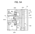
- FIG. 5 is an enlarged view of the Q2 part in FIG. 2, and FIG. 5A is an enlarged view of the Q3 part in FIG.
- the flow of oil is schematically indicated by arrows R10 to R32.
- oil 500 associated with an oil pool that may be formed on the inner peripheral surface of rotor shaft 314 due to the centrifugal force that accompanies rotation of rotor shaft 314 is schematically shown by hatching.
- the oil supplied to the cover oil passage 80 flows into the first oil passage 81 and flows axially through the first oil passage 81 (see arrow R12). Some of the oil that flows axially through the first oil passage 81 passes through the discharge hole 821 of the second oil passage 82 and accumulates on the inner peripheral surface (or on the inner peripheral surface) of the rotor shaft 314 as described above. The surface of the oil 500) is discharged to the landing position P2 (see arrow R22). In addition, of the oil that flows axially through the first oil passage 81, all of the remaining oil passes through the discharge hole 811 of the first oil passage 81 to the inner peripheral surface (or inner peripheral surface) of the rotor shaft 314 as described above. (See arrow R21).
- the oil discharged to the inner peripheral surface of the rotor shaft 314 in this way is transmitted along the inner peripheral surface of the rotor shaft 314 due to the centrifugal force accompanying the rotation of the rotor shaft 314. , along the inner peripheral surface of the rotor shaft 314 .
- the oil that travels along the inner peripheral surface of rotor shaft 314 is discharged to coil end portion 322A through third oil passage 831A (see arrow R31) by centrifugal force accompanying rotation of rotor shaft 314, It is discharged to the coil end portion 322B through the oil passage 831B (see arrow R32).
- the landing position P1 of the oil from the discharge hole 811 of the first oil passage 81 is higher than the landing position P2 of the oil from the discharge hole 821 of the second oil passage 82 in the third oil passage 831A.
- the landing position P2 of the oil from the discharge hole 821 of the second oil passage 82 is closer to the fourth oil passage 831B than the landing position P1 of the oil from the discharge hole 811 of the first oil passage 81 is.
- the amount of oil reaching the third oil passage 831A is greater than the oil reaching the fourth oil passage 831B, and Of the oil discharged from the discharge hole 821 of the second oil passage 82, the amount of oil reaching the fourth oil passage 831B is greater than the oil reaching the third oil passage 831A. Therefore, according to this embodiment, the amount of oil discharged from the discharge hole 811 of the first oil passage 81 and the amount of oil discharged from the discharge hole 821 of the second oil passage 82 are appropriately distributed. Thus, the amount of oil supplied to the third oil passage 831A and the amount of oil supplied to the fourth oil passage 831B can be distributed appropriately.
- the landing position P1 of the oil from the discharge hole 811 of the first oil passage 81 and the landing position P2 of the oil from the discharge hole 821 of the second oil passage 82 are aligned with the axis.
- the first oil passage 81 and the second oil passage 82 are formed by the cover member 252, but at least one of the first oil passage 81 and the second oil passage 82 is a cover member. It may be formed by a tubular member separate from the member 252 .
- the first oil passage 81 may be implemented by a hollow tubular member separate from the cover member 252 .
- the second oil passage 82 may be realized by forming a radial hole in the hollow tubular member. At least part of the effect of the present embodiment described above can be achieved by such a modification. In this modification, although the number of parts increases, the hollow tubular member can be made relatively long without considering the manufacturability of the cover member 252 .
- the second oil passage 82A may be formed downward from the first oil passage 81A.
- the second oil passage 82A can be formed at an axial position where it does not weigh on the bearing support portion 2524 when viewed in the radial direction.
- the end portion of the axial protrusion 2525 on the X direction X1 side terminates at an axial position slightly on the X direction X2 side of the fourth oil passage 831B.
- 2525 is intended to reduce the length in the axial direction, but is not limited to this.
- the end of the axial projection 2525 on the X direction X1 side may be located on the X direction X2 side of the axial center of the rotor core 312.
- the X direction X1 side of the axial projection 2525 The end portion may extend to the X direction X1 side of the fourth oil passage 831B.
- only the discharge hole 811 of the discharge hole 811 and the discharge hole 821 may be positioned on the X direction X1 side of the fourth oil passage 831B, or both may be positioned on the X direction X1 side of the fourth oil passage 831B. It may be positioned on the direction X1 side.
Landscapes
- Engineering & Computer Science (AREA)
- Power Engineering (AREA)
- Motor Or Generator Cooling System (AREA)
Abstract
ステータコイルを有するステータと、中空のロータシャフトと、ロータシャフトの外周面に固定されるロータコアとを有するロータと、ロータシャフトの軸方向一端側の軸方向の開口からロータシャフトの中空内部に延在し、油路を形成する油路形成部材とを備え、油路は、ロータシャフトの軸心よりも鉛直方向上側に中心軸を有する態様で軸方向に沿って延在し、ロータシャフトの内周面における第1位置に向けて油を吐出可能な第1油路と、ロータシャフトの内周面における第1位置よりも軸方向一端側に近い第2位置に向けて油を吐出可能な第2油路とを含む、回転電機が開示される。
Description
本開示は、回転電機に関する。
回転電機の軸方向一端側を覆うカバー部材の円筒突出部に管状の油路形成部材を取り付け、油路形成部材をロータシャフトの中空内部に延在させることで、油路形成部材の油路を介してロータシャフト内に油を供給する技術が知られている。ロータシャフトの中空内部に供給された油は、軸方向両側のコイルエンド部のそれぞれへと、ロータシャフトの中空内部で分配されてから供給される。
しかしながら、上記のような従来技術では、油は、ロータシャフトの中空内部に供給された後に、ロータシャフト内で、軸方向両側のコイルエンド部のそれぞれへ分配される。この場合、軸方向両側のコイルエンド部のそれぞれへ分配される油の量の均等化を図るべく、ロータシャフトの軸方向中心部付近に油が油路形成部材の油路から供給されるように、油路形成部材の軸長が比較的長くなる傾向がある。
そこで、本開示は、油路形成部材の油路からロータシャフトの中空内部に供給する段階で、軸方向の異なる位置への油の分配を実現することを目的とする。
1つの側面では、ステータコイルを有するステータと、
中空のロータシャフトと、前記ロータシャフトの外周面に固定されるロータコアとを有するロータと、
前記ロータシャフトの軸方向一端側の軸方向の開口から前記ロータシャフトの中空内部に延在し、油路を形成する油路形成部材とを備え、
前記油路は、
前記ロータシャフトの軸心よりも鉛直方向上側に中心軸を有する態様で軸方向に沿って延在し、前記ロータシャフトの内周面における第1位置に向けて油を吐出可能な第1油路と、
前記ロータシャフトの内周面における前記第1位置よりも前記軸方向一端側に近い第2位置に向けて油を吐出可能な第2油路とを含む、回転電機が提供される。
中空のロータシャフトと、前記ロータシャフトの外周面に固定されるロータコアとを有するロータと、
前記ロータシャフトの軸方向一端側の軸方向の開口から前記ロータシャフトの中空内部に延在し、油路を形成する油路形成部材とを備え、
前記油路は、
前記ロータシャフトの軸心よりも鉛直方向上側に中心軸を有する態様で軸方向に沿って延在し、前記ロータシャフトの内周面における第1位置に向けて油を吐出可能な第1油路と、
前記ロータシャフトの内周面における前記第1位置よりも前記軸方向一端側に近い第2位置に向けて油を吐出可能な第2油路とを含む、回転電機が提供される。
本開示によれば、油路形成部材の油路からロータシャフトの中空内部に供給する段階で、軸方向の異なる位置への油の分配を実現することが可能となる。
以下、添付図面を参照しながら各実施例について詳細に説明する。なお、図面の寸法比率はあくまでも一例であり、これに限定されるものではなく、また、図面内の形状等は、説明の都合上、部分的に誇張している場合がある。
以下では、まず、本実施例による回転電機1が好適に適用可能な車両用駆動システム100について説明してから、本実施例による回転電機1の詳細について説明する。
[駆動システム全体]
図1は、回転電機1を含む車両用駆動システム100のスケルトン図である。図1には、X方向と、X方向に沿ったX1側とX2側が定義されている。X方向は、第1軸A1の方向(以下、「軸方向」とも称する)に平行である。
図1は、回転電機1を含む車両用駆動システム100のスケルトン図である。図1には、X方向と、X方向に沿ったX1側とX2側が定義されている。X方向は、第1軸A1の方向(以下、「軸方向」とも称する)に平行である。
図1に示す例では、車両用駆動システム100は、車輪Wの駆動源となる回転電機1と、回転電機1と車輪Wとを結ぶ動力伝達経路に設けられた動力伝達機構7と、を備える。動力伝達機構7は、入力部材3と、カウンタギヤ機構4と、差動歯車機構5と、左右の出力部材6A、6Bと、を備える。
入力部材3は、入力軸31と、入力ギヤ32とを有する。入力軸31は、第1軸A1まわりに回転する回転部材である。入力ギヤ32は、回転電機1からの回転トルク(駆動力)をカウンタギヤ機構4に伝達するギヤである。入力ギヤ32は、入力部材3の入力軸31と一体的に回転するように、入力部材3の入力軸31に設けられる。
カウンタギヤ機構4は、動力伝達経路において、入力部材3と差動歯車機構5との間に配置される。カウンタギヤ機構4は、カウンタ軸41と、第1カウンタギヤ42と、第2カウンタギヤ43とを有する。
カウンタ軸41は、第2軸A2まわりに回転する回転部材である。第2軸A2は、第1軸A1に平行に延在する。第1カウンタギヤ42は、カウンタギヤ機構4の入力要素である。第1カウンタギヤ42は、入力部材3の入力ギヤ32と噛み合う。第1カウンタギヤ42は、カウンタ軸41と一体的に回転するように、カウンタ軸41に連結される。
第2カウンタギヤ43は、カウンタギヤ機構4の出力要素である。本実施例では、一例として、第2カウンタギヤ43は、第1カウンタギヤ42よりも小径に形成される。第2カウンタギヤ43は、カウンタ軸41と一体的に回転するように、カウンタ軸41に設けられる。
差動歯車機構5は、その回転軸心としての第3軸A3上に配置される。第3軸A3は、第1軸A1に平行に延在する。差動歯車機構5は、回転電機1の側から伝達される駆動力を、左右の出力部材6A、6Bに分配する。差動歯車機構5は、差動入力ギヤ51を備え、差動入力ギヤ51は、カウンタギヤ機構4の第2カウンタギヤ43と噛み合う。また、差動歯車機構5は、差動ケース52を備え、差動ケース52内には、ピニオンシャフトや、ピニオンギヤ、左右のサイドギヤ等が収容される。左右のサイドギヤは、それぞれ、左右の出力部材6A、6Bと一体的に回転するように連結される。
左右の出力部材6A、6Bのそれぞれは、左右の車輪Wに駆動連結される。左右の出力部材6A、6Bのそれぞれは、差動歯車機構5によって分配された駆動力を車輪Wに伝達する。なお、左右の出力部材6A、6Bは、2つ以上の部材により構成されてもよい。
このようにして回転電機1は、動力伝達機構7を介して車輪Wを駆動する。ただし、他の実施例では、車両用駆動システム100は、動力伝達機構7を含まない構成であってよい。また、他の実施例では、遊星歯車機構のような他の動力伝達機構が利用されてもよい。
[回転電機の詳細]
図2は、回転電機1の要部を概略的に示す断面図である。図3は、X方向に沿ってX1側から視たカバー部材の一部を示す平面図である。図4は、図2のQ1部の拡大図である。図2には、Z方向と、Z方向に沿ったZ1側とZ2側が定義されている。Z方向は軸方向に垂直な方向であり、上下方向に対応する。ここでは、Z1側を上側とし、Z2側を下側とする。ただし、Z方向は、重力方向に厳密に平行である必要はなく、重力方向に対して若干傾斜する方向であってもよい。
図2は、回転電機1の要部を概略的に示す断面図である。図3は、X方向に沿ってX1側から視たカバー部材の一部を示す平面図である。図4は、図2のQ1部の拡大図である。図2には、Z方向と、Z方向に沿ったZ1側とZ2側が定義されている。Z方向は軸方向に垂直な方向であり、上下方向に対応する。ここでは、Z1側を上側とし、Z2側を下側とする。ただし、Z方向は、重力方向に厳密に平行である必要はなく、重力方向に対して若干傾斜する方向であってもよい。
回転電機1は、ケース2内に、ロータ310及びステータ320を有する。
ケース2は、例えばアルミ等により形成されてよい。ケース2は、鋳造等により形成できる。ケース2は、モータケース250と、カバー部材252とを含む。ケース2は、回転電機1を収容する。また、図1に示した車両用駆動システム100の場合、ケース2は、図1に模式的に示すように、動力伝達機構7を更に収容してもよい。
モータケース250は、回転電機1を収容するモータ収容室SP1を形成する。なお、モータ収容室SP1は、回転電機1(及び/又は動力伝達機構7)を冷却及び/又は潤滑するための油を含む油密空間であってよい。モータケース250は、回転電機1の径方向外側を囲繞する周壁部を有する形態である。モータケース250は、複数の部材を結合して実現されてもよい。また、モータケース250は、X方向X1側で、動力伝達機構7を収容するギヤ収容室SP2を形成する他のケース部材254に一体化されてよい。
カバー部材252は、モータケース250のX方向X2側に結合される。カバー部材252は、モータ収容室SP1におけるX方向X2側を覆うカバーの形態である。この場合、カバー部材252は、モータケース250のX方向X2側の開口部を完全に又は略完全に閉塞する態様で覆ってもよい。なお、モータ収容室SP1の一部は、カバー部材252により形成されてもよい。
カバー部材252には、ロータ310を回転可能に支持するベアリング240が設けられる。すなわち、カバー部材252は、ベアリング240を支持するベアリング支持部2524を有する。
ベアリング240は、図2に示すように、ロータシャフト314のX2側の端部における径方向外側に設けられる。具体的には、ベアリング240は、アウタレースの径方向外側がカバー部材252に支持され、インナレースの径方向内側がロータシャフト314の外周面に支持される。なお、変形例では、逆に、ベアリング240は、インナレースの径方向内側がカバー部材252に支持され、アウタレースの径方向外側がロータシャフト314の内周面に支持されてもよい。
図2及び図3に示す例では、カバー部材252は、第1軸A1を中心とした円形状の底部2521と、底部2521の外周縁からX方向X1側へと突出する周壁部2522とを含み、周壁部2522のX方向X1側の端面がモータケース250に結合されている。底部2521におけるX方向X1側の中央部(第1軸A1を中心とした部分)には、X方向X1側に突出する円筒状のベアリング支持部2524が形成される。なお、ベアリング支持部2524は、第1軸A1を中心として同芯に形成される。
また、底部2521におけるX方向X1側の中央部(第1軸A1を中心とした部分)には、図4に示すように、円筒状のベアリング支持部2524の径方向内側に、軸方向突出部2525が形成される。軸方向突出部2525は、底部2521におけるX方向X1側の中央部(第1軸A1を中心とした部分)に、X方向X1側に突出する態様で形成される。
ロータ310は、ロータコア312と、ロータシャフト314とを備える。
ロータコア312は、例えば円環状の磁性体の積層鋼板からなってよい。ロータコア312の内部には、永久磁石(図示せず)が埋め込まれてよい。あるいは、永久磁石(図示せず)は、ロータコア312の外周面に取り付けられてもよい。なお、永久磁石(図示せず)の配列等は任意である。ロータコア312は、ロータシャフト314の外周面に固定され、ロータシャフト314と一体となって回転する。
ロータシャフト314は、回転電機1の回転軸である第1軸A1を画成する。ロータシャフト314は、ロータコア312が固定される部分よりもX2側において、ケース2のカバー部材252にベアリング240を介して回転可能に支持される。なお、ロータシャフト314は、回転電機1の軸方向他端側(X1側)において、ベアリング241を介してケース2に回転可能に支持される。このようにして、ロータシャフト314が軸方向両端で回転可能にケース2に支持されてよい。
ロータシャフト314は、X方向X1側で入力軸31に動力伝達可能に連結される。本実施例では、一例として、ロータシャフト314の内周面にはスプライン61が形成され、入力軸31の外周面に形成されるスプライン62と噛み合う態様で、スプライン嵌合される。
ロータシャフト314は、例えば中空管の形態であり、中空内部314Aを有する。中空内部314Aは、ロータシャフト314の軸方向の全長にわたり延在してよい。本実施例では、一例として、ロータシャフト314の内周面は、スプライン61が形成される区間を除いて、一定の内径を有する。ただし、他の実施例では、ロータシャフト314は、軸方向両端又は一端において小径化される形態であってよく、この場合、ロータシャフト314の内周面は、軸方向両端又は一端において、低減された内径を有してもよい。
ロータシャフト314の中空内部314Aは、軸心油路83として機能する。すなわち、中空内部314Aには、後述するカバー油路80を介して油が供給される。これにより、ロータシャフト314が冷却されることで、ロータコア312(及び永久磁石が設けられる場合は永久磁石)を径方向内側から冷却することが可能である。
ロータシャフト314の中空内部314Aには、油溜め用の堰部89が形成されてもよい。すなわち、ロータシャフト314は、内周面に、周方向全周にわたって径方向内側に突出する堰部89を有してもよい。図2に示す例では、一例として、堰部89は、ロータシャフト314の中空内部314Aに嵌合される円環状のプラグにより形成されている。
ロータシャフト314には、ステータ320のコイルエンド部322A、322Bにそれぞれ油を吐出する径方向の第3油路831A及び第4油路831Bが形成される。
第3油路831Aは、コイルエンド部322Aに径方向に対向する開口を有し、軸心油路83内の油をコイルエンド部322Aに向けて供給する。なお、図2に示す例では、第3油路831Aは、径方向に平行に直線状に延在するが、径方向に対して若干傾斜する斜め方向に直線状に延在してもよい。
第4油路831Bは、コイルエンド部322Bに径方向に対向する開口を有し、軸心油路83内の油をコイルエンド部322Bに向けて供給する。なお、図2に示す例では、第4油路831Bは、径方向に平行に直線状に延在するが、径方向に対して若干傾斜する斜め方向に直線状に延在してもよい。
ステータ320は、ステータコア321と、ステータコイル322とを備える。
ステータコア321は、例えば円環状の磁性体の積層鋼板からなってよい。ステータコア321の内周部には、径方向内側に突出するティース(図示せず)が放射状に形成される。
ステータコイル322は、例えば断面平角状又は断面円形状の導体に絶縁被膜が付与された形態であってよい。ステータコイル322は、ステータコア321のティース(図示せず)まわりに巻装される。なお、ステータコイル322は、例えば、1つ以上の並列関係で、Y結線で電気的に接続されてもよいし、Δ結線で電気的に接続されてもよい。
ステータコイル322は、ステータコア321のスロットから軸方向外側に突出する部分であるコイルエンド部322A、322Bを有する。コイルエンド部322Aは、X1側に位置し、コイルエンド部322Bは、X2側に位置する。
次に、図2から図4の参照を継続しつつ、本実施例の油路構造について説明する。
本実施例では、カバー部材252には、カバー油路80と、第1油路81と、第2油路82とが形成される。これにより、例えば第1油路81や第2油路82が、カバー部材252とは別体の管状部材により形成される場合に比べて、部品点数の低減を図ることができる。
カバー油路80は、カバー部材252の底部2521に形成される。カバー油路80は、第1軸A1又はその近傍を通る態様でカバー油路80に形成される。なお、カバー油路80は、後述する第1油路81に連通する限り、任意の形態であってよい。例えば、カバー油路80は、単なる空間であってもよいし、フィン等が設けられてもよい。また、カバー油路80は、第1軸A1まわりを周回する区間を有してもよいし、径方向に行き来しつつ第1軸A1まわりを周回する形態であってもよい。また、他の例では、カバー油路80には、冷却水路が形成されてもよい。この場合、カバー油路80内の油は、冷却水路内を流れる冷却水により低温化されてもよい。
カバー油路80は、図示しないオイルポンプの吐出側に連通する。この場合、オイルポンプから吐出された油は、カバー油路80に供給される。なお、オイルポンプは、機械式であってもよいし、電気モータにより駆動される電動式であってもよい。
第1油路81は、軸方向に直線状に延在する。第1油路81は、図4に示すように、第1軸A1に対して上側にオフセットした中心軸I1を有する。例えば、第1油路81の断面形状(中心軸I1に垂直な平面で切断したときの断面形状)は、円形であってよく、この場合、円形の中心が第1油路81の中心軸I1を形成する。なお、第1油路81の断面形状が円形以外である場合、第1油路81の中心軸I1は、断面形状の図心の集合により画成されてよい。
本実施例では、第1油路81は、カバー部材252の軸方向突出部2525に形成される。なお、図2及び図4に示す例では、第1油路81は、軸方向突出部2525の軸方向全体にわたって形成されている。なお、図2及び図4に示すように、カバー部材252の底部2521の軸方向の寸法が比較的大きい場合は、第1油路81のX方向X2側の端部が底部2521に形成されてもよい。
第1油路81は、X方向X2側の端部がカバー油路80に連通し、X方向X1側が開口する。第1油路81は、X方向X1側がロータシャフト314の中空内部314Aまで延在する。従って、軸方向突出部2525は、図2及び図4に示すように、X方向X1側がロータシャフト314の中空内部314Aに延在する。
第1油路81は、X1側の端部に軸方向の吐出孔811を有する。第1油路81には、カバー油路80から油が供給され、第1油路81に供給された油は、吐出孔811から、X方向X1側へと噴射(吐出)される。なお、図2には、第1油路81から油の吐出態様が矢印R21で模式的に示されている。第1油路81の吐出孔811から吐出される油は、主に、第3油路831A(X方向X1側のコイルエンド部322A)に供給されるように、好ましくは、比較的軸方向の長い距離、飛翔するように吐出される。
具体的には、第1油路81の吐出孔811から吐出される油の着地位置P1は、好ましくは、軸方向の第3油路831A及び第4油路831B間の中点位置P0よりも、第3油路831Aに近い位置である。ここで、第1油路81の吐出孔811から吐出される油の着地位置P1とは、ロータシャフト314の中空内部314Aの表面(すなわち、ロータシャフト314の内周面)における位置である。なお、第1油路81の吐出孔811から吐出される油の着地位置P1は、オイルポンプからの油の吐出圧に応じて変化するので、ここでの着地位置P1とは、例えば、オイルポンプからの油の吐出圧の最大値(実際の変化範囲の最大値)を基準としてよい。これは、後述する着地位置P2についても同様である。なお、図2に示す例では、第1油路81の吐出孔811から吐出される油は、中空内部314Aの表面(すなわち、ロータシャフト314の内周面)における第3油路831Aの手前側(吐出方向に視て手前側、すなわちX2側)に着地している。これにより、第1油路81の吐出孔811から吐出される油は、吐出方向の速度成分を有した状態で着地位置P1からロータシャフト314の内周面を伝いやすくなり、着地位置P1に対してX方向X1側の第3油路831Aへと流れやすくなる。この結果、第1油路81の吐出孔811から吐出される油を、第3油路831Aを介してコイルエンド部322Aに供給しやすくすることができる。
ところで、本実施例では、軸方向突出部2525は、X方向X2側から中空内部314Aに延在する。従って、軸方向突出部2525の軸方向の長さが長いほど、第1油路81の吐出孔811の軸方向の位置が、X方向X1側に来る。このため、軸方向突出部2525のX1側端部が第3油路831Aの軸方向位置を超えない範囲では、軸方向突出部2525の軸方向の長さが長いほうが、第1油路81の吐出孔811から吐出される油の着地位置P1を、X方向X1側の第3油路831Aに近づける観点からは有利となる。
他方、軸方向突出部2525の軸方向の長さが長くなると、カバー部材252の軸方向の体格が大きくなるため、材料コストや重量の観点から不利である。また、カバー部材252が鋳造により形成される場合、軸方向突出部2525の軸方向の長さが長くなると、カバー部材252を製造するための金型の軸方向の体格が大きくなり、金型のサイズの観点からも不利である。
この点、本実施例では、第1油路81は、中心軸I1が第1軸A1に対して上側にオフセットするので、軸方向突出部2525の軸方向の長さを過大とすることなく、第1油路81の吐出孔811から吐出される油の着地位置P1を、第3油路831Aに近づけることが可能である。
具体的には、第1油路81の中心軸I1が第1軸A1に対して上側にオフセットすると、吐出孔811の中心が第1軸A1に対して上側にオフセットする。従って、この場合、第1油路81の吐出孔811からの油は、第1軸A1よりも上側から吐出されることになる。吐出孔811から着地位置P1(ロータシャフト314の内周面における油の着地位置P1)までの軸方向の長さL1は、油の吐出速度が高いほど長くなり、かつ、吐出孔811の高さH1(着地位置P1からの高さ、図4参照)が大きいほど長くなる。吐出孔811の中心が第1軸A1に対して上側にオフセットすると、吐出孔811の高さ(着地位置P1からの高さ)H1が大きくなるので、吐出孔811から着地位置P1までの軸方向の長さL1を長くすることができる。これにより、軸方向突出部2525の軸方向の長さを過大とすることなく、吐出孔811から着地位置P1までの軸方向の長さL1を長くして、第1油路81の吐出孔811から吐出される油の着地位置P1を、第3油路831Aに近づけることが可能となる。
換言すると、本実施例によれば、第1油路81の中心軸I1を第1軸A1に対して上側にオフセットさせることで、軸方向突出部2525の軸方向の長さの低減を図りつつ、コイルエンド部322Aに供給される必要な量の油を確保できる。
なお、本実施例では、軸方向突出部2525(及びそれに伴い第1油路81)は、X方向X1側の端部が第4油路831BよりもX方向X2側で終端する。例えば、図2に示す例では、軸方向突出部2525のX方向X1側の端部は、第4油路831BよりもわずかにX方向X2側の軸方向位置で終端する。これにより、軸方向突出部2525の軸方向の長さの低減を図ることができる。
本実施例において、第1油路81は、好ましくは、吐出孔811において断面積(中心軸I1に垂直な平面で切断したときの断面での断面積)が小さくなる。すなわち、第1油路81は、好ましくは、吐出孔811における断面積が、吐出孔811に至るまでの経路中の断面積よりも小さい。この場合、吐出孔811からの油の吐出速度を効果的に高めることができる。この結果、吐出孔811から着地位置P1までの軸方向の長さL1を長くすることができる。
例えば、第1油路81の吐出孔811は、軸方向突出部2525の軸方向貫通孔(第1油路81)に挿入される円環状のプラグ70により形成されてもよい。プラグ70(図4参照)は、第1油路81における流路の絞り(オリフィス)として機能する。これにより、第1油路81を流れる油の流速を増加させて、油の吐出速度を高めることができる。なお、プラグ70を用いる場合、軸方向突出部2525には、第1油路81用の軸方向の孔を一定断面で形成でき、製造性が良好である。なお、この場合、プラグ70は、第1油路81用の軸方向の孔に嵌合されてよい。
第2油路82は、X方向X2側の端部がカバー油路80に連通し、X方向X1側かつ下側に開口する。本実施例では、第2油路82は、第1油路81を介してカバー油路80に連通する。すなわち、第2油路82は、第1油路81から分岐する形態である。本実施例では、第2油路82は、第1油路81から分岐して、X方向X1側かつ下側に向かう斜め方向に直線状に延在する。この場合、孔開け用の加工ドリルを利用して第2油路82を容易に形成できる。
本実施例では、第2油路82は、上述した第1油路81と同様、カバー部材252の軸方向突出部2525に形成される。すなわち、本実施例では、軸方向突出部2525は、ロータシャフト314の中空内部314A内に延在する部分において、第1軸A1に対して上側にオフセットした第1油路81を形成するとともに、第1油路81から斜め下向きに延在する第2油路82を形成する。なお、軸方向突出部2525は、ロータシャフト314の中空内部314A内に延在する部分において、外径がロータシャフト314の内径よりも小さく設定されている。そして、図2に示す例では、上述した堰部89は、径方向に視て、軸方向突出部2525に重なる位置に形成されている。
第2油路82は、軸方向突出部2525の下部に形成される。第2油路82は、X方向X1側かつ下側の端部に、X方向X1側かつ下側へ油を吐出する吐出孔821を有する。
第2油路82には、カバー油路80から第1油路81を介して油が供給され、第2油路82に供給された油は、X方向X1側かつ下側の吐出孔821から、X方向X1側かつ下側へと噴射(吐出)される。
なお、図2には、第2油路82から油の吐出態様が矢印R22で模式的に示されている。第2油路82の吐出孔821から吐出される油は、主に、第4油路831B(X方向X2側のコイルエンド部322B)に供給されるように、比較的軸方向の短い距離だけ、飛翔するように吐出される。図2に示す例では、吐出孔821からの吐出方向は、斜め下向きであるので、吐出孔821から着地位置P2までの軸方向の長さL2(図4及び図5参照)が短くなる。
第2油路82の吐出孔821から吐出される油の着地位置P2は、好ましくは、軸方向の第3油路831A及び第4油路831B間の中点位置P0よりも、第4油路831Bに近い位置である。また、堰部89が設けられる場合は、着地位置P2は、堰部89よりもX1側である。ここで、第2油路82の吐出孔821から吐出される油の着地位置P2とは、上述した着地位置P1と同様、ロータシャフト314の中空内部314Aの表面(すなわち、ロータシャフト314の内周面)における位置である。なお、図2に示す例では、第2油路82の吐出孔821から吐出される油は、中空内部314Aの表面(すなわち、ロータシャフト314の内周面)における第4油路831Bの手前側(吐出方向に視て手前側、すなわちX2側)に着地している。これにより、第2油路82の吐出孔821から吐出される油は、吐出方向の速度成分を有した状態で着地位置P2からロータシャフト314の内周面を伝いやすくなり、着地位置P2に対してX方向X1側の第4油路831Bへと流れやすくなる。この結果、第2油路82の吐出孔821から吐出される油を、第4油路831Bを介してコイルエンド部322Bに供給しやすくすることができる。
ところで、本実施例では、第2油路82は、軸方向突出部2525のX方向X1側の端部付近に形成されるが、斜め下向きに延在する形態であるので、加工性の観点から、軸方向突出部2525の下部が比較的大きい厚み(径方向の厚み)を有することが望ましい。
この点、本実施例では、上述したように、軸方向突出部2525に形成される第1油路81は、第1軸A1に対して上側にオフセットするので、第1油路81を上側にオフセットする分だけ、軸方向突出部2525の下部の厚みを比較的大きく確保することが容易となる。この結果、軸方向突出部2525の下部に第2油路82を容易に形成できる。
また、本実施例では、第2油路82が形成される軸方向突出部2525は、カバー部材252の一部であるので、ケース2とは別体の冷却パイプを軸方向突出部2525に代えて設ける場合に比べて、コスト的に有利となる。換言すると、本実施例によれば、ケース2とは別体の冷却パイプを廃止しても適切に油を分配できる。
ここで、本実施例では、第2油路82が形成される軸方向突出部2525は、カバー部材252の一部であり、図4に示すように、ベアリング支持部2524の径方向内側に配置される。また、ベアリング支持部2524は、径方向に視て第2油路82に重なる。このような位置関係の場合、孔開け用の加工ドリルを利用して第2油路82を径方向に平行に形成することは、スペース確保の観点から難しい。
この点、本実施例によれば、第2油路82が斜め下向きに延在する形態であるので、径方向に視てベアリング支持部2524に重なる位置関係となる第2油路82についても、孔開け用の加工ドリルを利用して、比較的容易に形成できる。
換言すると、本実施例によれば、軸方向突出部2525に形成される第1油路81が、第1軸A1に対して上側にオフセットすることで、上述したように、軸方向突出部2525の下部を比較的厚くして第2油路82を斜め下向きに形成でき、その結果、第2油路82を、径方向に視てベアリング支持部2524に重なる位置に形成できる。
次に、図5を参照して、本実施例の油路構造における油の流れについて概説する。
図5は、図2のQ2部の拡大図であり、図5Aは、図5のQ3部の拡大図である。図5には、油の流れが、矢印R10からR32により模式的に示されている。なお、図5には、ロータシャフト314の回転に伴う遠心力の影響でロータシャフト314の内周面に形成されうる油溜まり係る油500がハッチングにより模式的に示されている。
カバー油路80に供給された油(矢印R10参照)は、第1油路81に流入し、第1油路81を軸方向に流れる(矢印R12参照)。第1油路81を軸方向に流れる油のうちの、一部は、第2油路82の吐出孔821を介して上述したようにロータシャフト314の内周面(又は内周面上に溜まる油500の表面)における着地位置P2へと吐出される(矢印R22参照)。また、第1油路81を軸方向に流れる油のうちの、残りの全部は、第1油路81の吐出孔811を介して上述したようにロータシャフト314の内周面(又は内周面上に溜まる油500の表面)における着地位置P1へと吐出される(矢印R21参照)。回転電機1の動作中、このようにして、ロータシャフト314の内周面に吐出された油は、ロータシャフト314の回転に伴う遠心力の影響で、ロータシャフト314の内周面を伝う態様で、ロータシャフト314の内周面に沿って流れる。そして、ロータシャフト314の内周面を伝う油は、ロータシャフト314の回転に伴う遠心力によって、第3油路831Aを介してコイルエンド部322Aに吐出されるか(矢印R31参照)、第4油路831Bを介してコイルエンド部322Bに吐出される(矢印R32参照)。
ここで、本実施例では、第1油路81の吐出孔811からの油の着地位置P1は、第2油路82の吐出孔821からの油の着地位置P2よりも、第3油路831Aに近い。また、第2油路82の吐出孔821からの油の着地位置P2は、第1油路81の吐出孔811からの油の着地位置P1よりも、第4油路831Bに近い。
従って、本実施例では、第1油路81の吐出孔811から吐出される油のうちの、第3油路831Aに至る油は、第4油路831Bに至る油よりも多くなり、かつ、第2油路82の吐出孔821から吐出される油のうちの、第4油路831Bに至る油は、第3油路831Aに至る油よりも多くなる。このため、本実施例によれば、第1油路81の吐出孔811から吐出される油の量と、第2油路82の吐出孔821から吐出される油の量とを適切に分配することで、第3油路831Aに供給される油の量と、第4油路831Bに供給される油の量とを適切に分配できる。
このようにして、本実施例によれば、第1油路81の吐出孔811からの油の着地位置P1と、第2油路82の吐出孔821からの油の着地位置P2とを、軸方向に有意に異ならせることで、カバー油路80からロータシャフト314の中空内部314Aに供給する段階で、軸方向の異なる位置に形成される第3油路831A及び第4油路831B(及びそれに伴いコイルエンド部322A、322Bのそれぞれ)への油の分配を実現できる。
以上、各実施例について詳述したが、特定の実施例に限定されるものではなく、特許請求の範囲に記載された範囲内において、種々の変形及び変更が可能である。また、前述した実施例の構成要素を全部又は複数を組み合わせることも可能である。また、各実施例の効果のうちの、従属項に係る効果は、上位概念(独立項)とは区別した付加的効果である。
例えば、上述した実施例では、第1油路81及び第2油路82は、カバー部材252により形成されているが、第1油路81及び第2油路82の少なくともいずれか一方が、カバー部材252とは別体の管状部材により形成されてもよい。例えば、第1油路81は、カバー部材252とは別体の中空の管状部材により実現されてもよい。この場合、中空の管状部材に径方向の孔を形成することで、第2油路82が実現されてもよい。かかる変形例によっても、上述した本実施例の効果の少なくとも一部が奏される。なお、かかる変形例の場合、部品点数が増加するものの、カバー部材252の製造性を考慮することなく中空の管状部材の比較的長くすることが可能である。
また、上述した実施例では、軸方向突出部2525(及びそれに伴い第1油路81)は、X方向X1側の端部が第4油路831BよりもX方向X2側で終端するが、これに限られない。例えば、前出した図4と同様の断面部分を示す図6に示すように、カバー部材252Aの軸方向突出部2525A(及びそれに伴い第1油路81A)は、X方向X1側の端部が第4油路831BよりもX方向X1に延在してもよい。この場合、第2油路82Aは、第1油路81Aから下向きに形成されてもよい。なお、この場合、第2油路82Aは、径方向に視てベアリング支持部2524に重さならない軸方向位置に形成できる。
また、上述した実施例では、軸方向突出部2525のX方向X1側の端部は、第4油路831BよりもわずかにX方向X2側の軸方向位置で終端することで、軸方向突出部2525の軸方向の長さの低減を図るが、これに限られない。例えば、軸方向突出部2525のX方向X1側の端部は、ロータコア312の軸方向中央部よりもX方向X2側に位置すればよく、この場合、軸方向突出部2525のX方向X1側の端部は、第4油路831BよりもX方向X1側まで延在してもよい。かかる構成によっても、上述した本実施形態と同様の効果を得ることができる。なお、この場合、吐出孔811及び吐出孔821のうちの、吐出孔811だけが第4油路831BよりもX方向X1側に位置してもよいし、双方が第4油路831BよりもX方向X1側に位置してもよい。
1・・・回転電機、320・・・ステータ、322・・・ステータコイル、310・・・ロータ、312・・・ロータコア、314・・・ロータシャフト、314A・・・中空内部、252・・・カバー部材(油路形成部材)、2524・・・ベアリング支持部、81・・・第1油路、811・・・吐出孔、82・・・第2油路、821・・・吐出孔、831A・・・第3油路、831B・・・第4油路、240・・・ベアリング
Claims (5)
- ステータコイルを有するステータと、
中空のロータシャフトと、前記ロータシャフトの外周面に固定されるロータコアとを有するロータと、
前記ロータシャフトの軸方向一端側の軸方向の開口から前記ロータシャフトの中空内部に延在し、油路を形成する油路形成部材とを備え、
前記油路は、
前記ロータシャフトの軸心よりも鉛直方向上側に中心軸を有する態様で軸方向に沿って延在し、前記ロータシャフトの内周面における第1位置に向けて油を吐出可能な第1油路と、
前記ロータシャフトの内周面における前記第1位置よりも前記軸方向一端側に近い第2位置に向けて油を吐出可能な第2油路とを含む、回転電機。 - 前記第1油路からの油の吐出孔及び前記第2油路からの油の吐出孔は、前記ロータコアの軸方向中央部よりも前記軸方向一端側に位置する、請求項1に記載の回転電機。
- 前記第1油路からの油の吐出孔及び前記第2油路からの油の吐出孔は、前記ロータコアよりも前記軸方向一端側に位置する、請求項1に記載の回転電機。
- 前記ロータシャフトは、
軸方向両側のコイルエンド部のうちの、前記軸方向一端側から遠い側のコイルエンド部に向けて油を吐出可能な第3油路と、
軸方向両側のコイルエンド部のうちの、前記軸方向一端側に近い側のコイルエンド部に向けて油を吐出可能な第4油路とを有し、
前記第1油路は、前記第4油路よりも前記軸方向一端側で終端し、
前記第2油路は、前記第1油路から分岐して斜め下向きに延在する、請求項1から3のうちのいずれか1項に記載の回転電機。 - 前記油路形成部材は、前記ステータ及び前記ロータの前記軸方向一端側を覆うカバー部材であり、
前記カバー部材は、前記ロータシャフトをベアリングを介して回転可能に支持するベアリング支持部を有する、請求項1から4のうちのいずれか1項に記載の回転電機。
Applications Claiming Priority (2)
| Application Number | Priority Date | Filing Date | Title |
|---|---|---|---|
| JP2021048862A JP2024081806A (ja) | 2021-03-23 | 2021-03-23 | 回転電機 |
| JP2021-048862 | 2021-03-23 |
Publications (1)
| Publication Number | Publication Date |
|---|---|
| WO2022201742A1 true WO2022201742A1 (ja) | 2022-09-29 |
Family
ID=83396699
Family Applications (1)
| Application Number | Title | Priority Date | Filing Date |
|---|---|---|---|
| PCT/JP2022/000360 Ceased WO2022201742A1 (ja) | 2021-03-23 | 2022-01-07 | 回転電機 |
Country Status (2)
| Country | Link |
|---|---|
| JP (1) | JP2024081806A (ja) |
| WO (1) | WO2022201742A1 (ja) |
Cited By (1)
| Publication number | Priority date | Publication date | Assignee | Title |
|---|---|---|---|---|
| US20230132520A1 (en) * | 2021-10-29 | 2023-05-04 | Nidec Corporation | Rotating electrical machine and drive device |
Citations (3)
| Publication number | Priority date | Publication date | Assignee | Title |
|---|---|---|---|---|
| JP2015231266A (ja) * | 2014-06-04 | 2015-12-21 | 株式会社デンソー | 回転電機 |
| JP2020028213A (ja) * | 2018-08-08 | 2020-02-20 | アイシン・エィ・ダブリュ株式会社 | 回転電機用ロータ及び当該回転電機用ロータを備えた車両用駆動装置 |
| JP2020141475A (ja) * | 2019-02-28 | 2020-09-03 | 本田技研工業株式会社 | 回転電機 |
-
2021
- 2021-03-23 JP JP2021048862A patent/JP2024081806A/ja active Pending
-
2022
- 2022-01-07 WO PCT/JP2022/000360 patent/WO2022201742A1/ja not_active Ceased
Patent Citations (3)
| Publication number | Priority date | Publication date | Assignee | Title |
|---|---|---|---|---|
| JP2015231266A (ja) * | 2014-06-04 | 2015-12-21 | 株式会社デンソー | 回転電機 |
| JP2020028213A (ja) * | 2018-08-08 | 2020-02-20 | アイシン・エィ・ダブリュ株式会社 | 回転電機用ロータ及び当該回転電機用ロータを備えた車両用駆動装置 |
| JP2020141475A (ja) * | 2019-02-28 | 2020-09-03 | 本田技研工業株式会社 | 回転電機 |
Cited By (1)
| Publication number | Priority date | Publication date | Assignee | Title |
|---|---|---|---|---|
| US20230132520A1 (en) * | 2021-10-29 | 2023-05-04 | Nidec Corporation | Rotating electrical machine and drive device |
Also Published As
| Publication number | Publication date |
|---|---|
| JP2024081806A (ja) | 2024-06-19 |
Similar Documents
| Publication | Publication Date | Title |
|---|---|---|
| JP5448559B2 (ja) | モータの冷却構造 | |
| JP5734765B2 (ja) | 回転電機の冷却構造 | |
| JP5470015B2 (ja) | 回転電機 | |
| JP4293263B2 (ja) | 車両用動力伝達装置 | |
| JP5367276B2 (ja) | 電動機の潤滑冷却構造 | |
| CN106059171B (zh) | 电机装置、机动车辆变速箱及用于生产电机装置的方法 | |
| CN105637741B (zh) | 电动机 | |
| JP5583254B2 (ja) | 電動機の潤滑冷却構造 | |
| CN110601446B (zh) | 转子的制造方法 | |
| US11205939B2 (en) | Rotary electric machine | |
| JP2018535643A (ja) | 冷却媒体分配要素を有する組み立てられた中空ロータシャフト | |
| JP2013132151A (ja) | 回転電機及び回転電機冷却システム | |
| US11515746B2 (en) | Cooling mechanism for vehicle electric motor | |
| JP7483928B2 (ja) | 回転子、回転電機 | |
| JP6903698B2 (ja) | 回転電機のロータ | |
| JP2017131078A (ja) | モータの冷却構造 | |
| CN112840538A (zh) | 旋转电机和马达单元 | |
| WO2017119240A1 (ja) | インホイールモータ駆動装置 | |
| JP2024081806A (ja) | 回転電機 | |
| JP2019129609A (ja) | 車両用冷却装置 | |
| CN116032044A (zh) | 转子结构及电机 | |
| JP2010246330A (ja) | 電動機 | |
| JP5730740B2 (ja) | 回転電機 | |
| JP2020141542A (ja) | 回転電機のロータ | |
| US20250343457A1 (en) | Electric motor with rotor having axial cooling channel |
Legal Events
| Date | Code | Title | Description |
|---|---|---|---|
| 121 | Ep: the epo has been informed by wipo that ep was designated in this application |
Ref document number: 22774547 Country of ref document: EP Kind code of ref document: A1 |
|
| NENP | Non-entry into the national phase |
Ref country code: DE |
|
| 122 | Ep: pct application non-entry in european phase |
Ref document number: 22774547 Country of ref document: EP Kind code of ref document: A1 |
|
| NENP | Non-entry into the national phase |
Ref country code: JP |