WO2022201717A1 - 溶銑滓高さ検出方法および溶銑滓高さ検出装置 - Google Patents
溶銑滓高さ検出方法および溶銑滓高さ検出装置 Download PDFInfo
- Publication number
- WO2022201717A1 WO2022201717A1 PCT/JP2021/048557 JP2021048557W WO2022201717A1 WO 2022201717 A1 WO2022201717 A1 WO 2022201717A1 JP 2021048557 W JP2021048557 W JP 2021048557W WO 2022201717 A1 WO2022201717 A1 WO 2022201717A1
- Authority
- WO
- WIPO (PCT)
- Prior art keywords
- molten iron
- iron slag
- blast furnace
- height
- slag
- Prior art date
- Legal status (The legal status is an assumption and is not a legal conclusion. Google has not performed a legal analysis and makes no representation as to the accuracy of the status listed.)
- Ceased
Links
Images

Classifications
-
- G—PHYSICS
- G01—MEASURING; TESTING
- G01F—MEASURING VOLUME, VOLUME FLOW, MASS FLOW OR LIQUID LEVEL; METERING BY VOLUME
- G01F23/00—Indicating or measuring liquid level or level of fluent solid material, e.g. indicating in terms of volume or indicating by means of an alarm
- G01F23/0007—Indicating or measuring liquid level or level of fluent solid material, e.g. indicating in terms of volume or indicating by means of an alarm for discrete indicating and measuring
-
- C—CHEMISTRY; METALLURGY
- C21—METALLURGY OF IRON
- C21B—MANUFACTURE OF IRON OR STEEL
- C21B7/00—Blast furnaces
- C21B7/24—Test rods or other checking devices
-
- F—MECHANICAL ENGINEERING; LIGHTING; HEATING; WEAPONS; BLASTING
- F27—FURNACES; KILNS; OVENS; RETORTS
- F27B—FURNACES, KILNS, OVENS OR RETORTS IN GENERAL; OPEN SINTERING OR LIKE APPARATUS
- F27B1/00—Shaft or like vertical or substantially vertical furnaces
- F27B1/10—Details, accessories or equipment specially adapted for furnaces of these types
- F27B1/28—Arrangements of monitoring devices, of indicators, of alarm devices
-
- F—MECHANICAL ENGINEERING; LIGHTING; HEATING; WEAPONS; BLASTING
- F27—FURNACES; KILNS; OVENS; RETORTS
- F27D—DETAILS OR ACCESSORIES OF FURNACES, KILNS, OVENS OR RETORTS, IN SO FAR AS THEY ARE OF KINDS OCCURRING IN MORE THAN ONE KIND OF FURNACE
- F27D21/00—Arrangement of monitoring devices; Arrangement of safety devices
-
- F—MECHANICAL ENGINEERING; LIGHTING; HEATING; WEAPONS; BLASTING
- F27—FURNACES; KILNS; OVENS; RETORTS
- F27D—DETAILS OR ACCESSORIES OF FURNACES, KILNS, OVENS OR RETORTS, IN SO FAR AS THEY ARE OF KINDS OCCURRING IN MORE THAN ONE KIND OF FURNACE
- F27D21/00—Arrangement of monitoring devices; Arrangement of safety devices
- F27D21/0028—Devices for monitoring the level of the melt
-
- G—PHYSICS
- G01—MEASURING; TESTING
- G01F—MEASURING VOLUME, VOLUME FLOW, MASS FLOW OR LIQUID LEVEL; METERING BY VOLUME
- G01F23/00—Indicating or measuring liquid level or level of fluent solid material, e.g. indicating in terms of volume or indicating by means of an alarm
- G01F23/22—Indicating or measuring liquid level or level of fluent solid material, e.g. indicating in terms of volume or indicating by means of an alarm by measuring physical variables, other than linear dimensions, pressure or weight, dependent on the level to be measured, e.g. by difference of heat transfer of steam or water
-
- G—PHYSICS
- G01—MEASURING; TESTING
- G01F—MEASURING VOLUME, VOLUME FLOW, MASS FLOW OR LIQUID LEVEL; METERING BY VOLUME
- G01F23/00—Indicating or measuring liquid level or level of fluent solid material, e.g. indicating in terms of volume or indicating by means of an alarm
- G01F23/22—Indicating or measuring liquid level or level of fluent solid material, e.g. indicating in terms of volume or indicating by means of an alarm by measuring physical variables, other than linear dimensions, pressure or weight, dependent on the level to be measured, e.g. by difference of heat transfer of steam or water
- G01F23/28—Indicating or measuring liquid level or level of fluent solid material, e.g. indicating in terms of volume or indicating by means of an alarm by measuring physical variables, other than linear dimensions, pressure or weight, dependent on the level to be measured, e.g. by difference of heat transfer of steam or water by measuring the variations of parameters of electromagnetic or acoustic waves applied directly to the liquid or fluent solid material
- G01F23/296—Acoustic waves
- G01F23/2961—Acoustic waves for discrete levels
Definitions
- the present invention relates to a blast furnace molten iron slag height detection method and a molten iron slag height detection device.
- iron ore and other main raw materials and coke as a reducing agent are alternately charged from the top of the furnace, and heated air is blown from the tuyeres at the bottom of the furnace.
- the charged iron ore is melted and reduced in the furnace to become hot metal, which is discharged from the taphole installed at the bottom of the furnace together with slag, which is the molten product of the gangue.
- Hot metal and slag are constantly discharged from one of the tapping holes provided in the blast furnace while being alternately used. .
- Specific examples of adverse effects include increased pressure loss in the furnace, molten iron slag reaching the height of the tuyere and damaging the tuyere, and molten iron slag flowing backward from the tuyere to the blowpipe direction, making it impossible to blow air. Things are mentioned.
- molten iron slag reaching the height of the tuyere and damaging the tuyere
- molten iron slag flowing backward from the tuyere to the blowpipe direction making it impossible to blow air. Things are mentioned.
- tapping slag the weight measurement result of hot metal slag tapped from the tapping hole
- amount of slag to be produced calculated from the amount of raw material charged are calculated in balance.
- the height of hot metal slag is controlled.
- the weight measurement result of tapped slag can be obtained only at tapping cycles of 2 to 3 hours, information on the height of molten slag can be obtained only at this time interval. Therefore, it is extremely important to obtain more immediate information on the height of hot metal slag for stable operation of the blast furnace.
- Patent Document 1 As a technique for measuring the height of molten iron slag, for example, in Patent Document 1, a transmitter is installed on the furnace wall of a blast furnace, an elastic wave is emitted from the transmitter, and the height of the molten slag in the blast furnace is determined based on the reflected echo. Techniques for detecting slackness are disclosed. Further, Patent Document 2 discloses a technique for measuring the height of molten iron slag by applying a signal current from four electrodes installed on the wall of a blast furnace and detecting a voltage response to the signal current.
- Patent Documents 1 and 2 both require a transmitter that emits elastic waves and an electrode that applies a signal current in addition to a measuring device that receives signals from inside the furnace.
- facilities such as blow pipes for blowing air, hole opening machines, hot metal gutter cover cranes, etc. are concentrated.
- the furnace body in the lower part of the blast furnace generates a great deal of dust and radiant heat during the tapping operation, it is necessary to have an extra device for transmitting signals in addition to the measuring device.
- the present invention has been made in view of such problems of the prior art, and an object of the present invention is to provide a molten iron slag height detection method capable of obtaining the molten iron slag height without using a device for transmitting a signal to a blast furnace. and to provide a hot metal slag height detection device.
- Means for solving the above problems are as follows.
- a molten iron slag height detection device for detecting the height of molten iron slag in a blast furnace, comprising: a vibration meter provided on the furnace wall at the bottom of the blast furnace for measuring the vibration strength of the furnace wall; The vibration intensity is frequency-analyzed to calculate the vibration intensity in a predetermined frequency band, and the molten iron slag height of the blast furnace is calculated using the corresponding relationship between the vibration intensity in the predetermined frequency band and the molten iron slag height.
- a molten iron slag height detection device comprising: an arithmetic device for calculating
- the molten iron slag height detection method and the molten iron slag height detection device detect the molten iron slag height of the blast furnace by measuring the vibration intensity of the vibration generated by the blast furnace itself during operation.
- the molten iron slag height detection method can be detected without using a device for transmitting a signal to the blast furnace. It is possible to suppress the difficulty of conservation of
- FIG. 2 is a schematic diagram showing an experimental model used to confirm the relationship between the vibration of the furnace wall and the height of molten iron slag in the lower part of the blast furnace; A waveform of vibration intensity that appears in a frequency band of 600 Hz to 1000 Hz is shown. It is a graph which shows the relationship between vibration peak intensity and liquid level height. 5 is a graph showing transitions of vibration peak intensity and molten iron slag balance for each number of times of tapping. 4 is a graph showing the relationship between the normalized vibration peak intensity and the normalized hot metal slag balance.
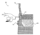
- FIG. 1 is a schematic cross-sectional view of the vicinity of the lower part of a blast furnace 10.
- Iron ore and coke which are raw materials, are charged alternately and in layers from the top of the blast furnace 10 into the furnace wall 12, and from the tuyeres 14 provided in the lower part of the furnace wall 12, hot air that is an oxygen-containing gas and A reducing material such as pulverized coal is injected.
- Carbon contained in coke and pulverized coal is burned by the oxygen-containing gas blown from the tuyeres 14, thereby generating high-temperature reducing gas.
- the hot reducing gas melts and reduces the iron ore to produce hot metal.
- the high-temperature reducing gas used for melting and reducing the iron ore is then discharged from the furnace top as furnace top gas.
- the produced molten iron and molten iron slag 18 composed of slag by-produced during the production of the molten iron are stored in the bottom of the furnace and discharged from tapping holes 16 provided in the lower part of the blast furnace 10 .
- the present inventors focused on the fluctuation of the blast pressure affected by the height of the molten iron slag 18 and the vibration of a specific frequency band caused by the collision of coke on the furnace wall 12 in the raceway, and the vibration intensity
- the present invention has been completed by finding that the change in the height of the hot metal slag 18 can be detected by detecting .
- the molten iron slag height detection device 20 is used to detect the height of the molten iron slag 18 stored at the bottom of the furnace.
- the molten iron slag height detection device 20 has a vibrometer 22 and an arithmetic device 24 .
- a vibration meter 22 is provided in the hearth portion of the furnace wall 12 in the lower part of the furnace to measure the vibration intensity of the furnace wall 12 and output it to the arithmetic unit 24 .
- the vibrometer 22 is, for example, a piezoelectric element. Note that the vibration meter 22 is not limited to a piezoelectric element, and a laser rangefinder may be used to measure the displacement of the furnace wall 12.
- a coil or the like may be used to electromagnetically measure vibration. may be used to measure vibration mechanically.
- a piezoelectric element that can be directly installed on the furnace wall 12 and has few moving parts.
- the computing device 24 is a general-purpose computer such as a personal computer having a computing section such as a CPU and a storage section such as a memory.
- the computing device 24 frequency-analyzes the vibration intensity obtained from the vibrometer 22, and calculates the vibration intensity in a predetermined frequency band. Further, the computing device 24 stores in advance a regression equation showing the correspondence relationship between the vibration intensity of the frequency band and the height of the hot metal slag.
- the hot metal slag height is obtained using In this manner, the molten iron slag height detection method according to the present embodiment detects the molten iron slag height in the blast furnace without using a device that transmits a signal to the blast furnace 10 .
- FIG. 2 is a schematic diagram showing an experimental model 30 used to confirm the relationship between the vibration of the furnace wall 12 in the lower part of the blast furnace and the height of molten iron slag.
- the experimental model 30 has a container 32 , two blower tuyeres 36 , a liquid inlet hole 44 , a piezoelectric element 40 and a data logger 42 .
- the container 32 imitates a part of the lower part of the blast furnace 10, and is an acrylic container with a height of 950 mm, a depth of 120 mm, a top width of 460 mm, and a bottom width of 380 mm.
- the top of container 32 was left open for filling with filler particles 34 .
- Two blower tuyeres 36 were provided on the sides of the container 32 at a height of 185 mm from the bottom.
- One liquid inflow hole 44 was provided at the bottom of the container 32 and at the center of gravity of the bottom surface.
- a flow control valve 38 is installed upstream of the blower tuyere 36 so that the amount of air blown from the blower tuyere 36 can be adjusted.
- a piezoelectric element 40 is installed between the two blower tuyeres 36, the vibration is converted into an electric signal by the piezoelectric element 40, and the electric signal is collected and recorded by the data logger 42, so that the change in the vibration intensity over time is obtained. was measured.
- the container 32 was filled with high-density polyethylene pellets (specific gravity 0.922) with a diameter of 3.4 mm as the filling particles 34, and the container 32 was filled with water from the liquid inflow hole 44 to a predetermined height.
- an experiment was conducted by blowing air from the blower tuyeres 36 at a predetermined airflow rate. Experimental conditions are shown in Table 1 below.
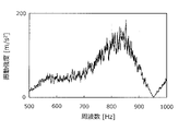
- FIG. 3 shows waveforms of vibration intensity appearing in a frequency band of 600 Hz to 1000 Hz.
- the horizontal axis is frequency (Hz) and the vertical axis is vibration intensity (m/s 2 ).
- this waveform has a broad peak in the frequency band of 800 Hz to 900 Hz, so the relationship between the peak intensity of the peak and the liquid level was confirmed.
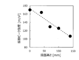
- FIG. 4 is a graph showing the relationship between vibration peak intensity and liquid level.
- the horizontal axis of FIG. 4 is the liquid level (mm), and the vertical axis is the intensity (m/s 2 ) of the vibration peak appearing in the frequency band of 800 Hz to 900 Hz.
- the intensity of the vibration peak decreased as the liquid level increased, confirming a linear negative correlation between the liquid level height and the vibration peak intensity.
- the height of molten iron slag in a blast furnace can also be detected using the vibration generated by the blast furnace.
- a piezoelectric vibration meter was installed on the furnace wall shell between the tuyeres, and the frequency characteristics were analyzed from the measurement results.
- a vibration peak having a peak at a frequency of approximately 900 Hz appeared, and the vibration peak intensity was compared with the molten iron slag balance.
- the hot metal slag balance means a value obtained by subtracting the tapped slag amount in terms of volume from the amount of ironmaking slag in terms of volume.
- a hot metal slag balance of "0" means that the amount of ironmaking slag is equal to the amount of tapping slag.
- the hot metal slag balance is a positive value, it means that the amount of tapped slag is less than the amount of slag produced, so the slag height is high.
- the hot metal slag balance is a negative value, it means that the amount of tapped slag is larger than the amount of slag produced, so the slag height is low.
- the amount of ironmaking slag is a calculated value obtained from the oxygen balance of the blast furnace per unit time, the ratio of oxygen contained in iron oxide in the raw material charged from the top of the furnace, and the ratio of gangue in the charged raw material. was used. Specifically, the pig iron production amount was calculated using the following formula (1), the slag production amount was calculated using the following formula (2), and the iron production slag amount was calculated by adding these values.
- Wp is the amount of pig iron (t/hour)
- Ws is the amount of slag ( t /hour).
- N top is the amount of oxygen atoms per unit time in the top gas (mol/hour)
- N tuy is the amount of oxygen atoms per unit blown from the tuyeres (mol/hour).
- R Fe/O is the average number of iron atoms (-) per oxygen atom in the iron oxide in the raw material charged from the furnace top
- M Fe is the molar mass of iron (t/mol)
- R FeHM is the mass fraction (-) of iron in hot metal
- R G/Fe is the mass of charged gangue per ton of hot metal (t/hot metal). Note that (-) indicates dimensionlessness.
- N top is obtained by analyzing the components of the furnace top gas.
- N tuy can be obtained by analyzing the components of the blast gas blown from the tuyeres.
- R Fe/O and R G/Fe can be obtained by analyzing the composition of raw materials charged from the top of the furnace.
- R FeHM is obtained by component analysis of hot metal tapped from the tap hole.
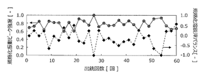
- Fig. 5 is a graph showing changes in vibration peak intensity and hot metal slag balance for each number of times of tapping.
- the horizontal axis represents the tapping number (times)
- the left vertical axis represents the normalized vibration peak intensity (-)
- the right vertical axis represents the normalized hot metal slag balance (-).
- Both the normalized vibration peak intensity and the normalized hot metal balance are the maximum absolute values of the vibration peak intensity and the hot metal balance during the target period, and are normalized values obtained by dividing the vibration peak intensity and the hot metal balance. .
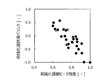
- FIG. 6 is a graph showing the relationship between the normalized vibration peak intensity and the normalized molten iron slag balance.
- the horizontal axis of FIG. 6 is the normalized vibration peak intensity (-), and the vertical axis is the normalized molten iron slag balance (-).
- FIG. 6 it was confirmed that there is a linear negative correlation between the normalized vibration peak intensity and the normalized molten iron slag balance, as in FIG. That is, it was confirmed that the vibration intensity in a specific frequency band among the vibrations generated from the furnace body in the lower part of the blast furnace has a linear negative correlation with the molten iron slag height.
- the vibration intensity of the frequency band specified during the operation of the blast furnace is measured, and the measured vibration intensity and the regression equation obtained in advance are used to determine the molten iron in the blast furnace. Find the slag height.
- the height of molten iron slag in the blast furnace can be obtained without using a device that transmits signals to the blast furnace, and as a result, it becomes difficult to arrange the equipment in the lower part of the blast furnace and to maintain the equipment. becoming suppressed.
- the hot metal slag height can be calculated by
- the molten iron slag height is calculated as described above, so it is possible to obtain a regression equation that shows the correspondence between the vibration intensity of the frequency band and the molten iron slag height at any time.
- the calculation accuracy of the molten iron height calculated from the reference molten iron slag height and the molten iron slag balance decreases as the blast furnace operation continues from the time when the reference molten iron slag height is obtained.
Landscapes
- Engineering & Computer Science (AREA)
- Physics & Mathematics (AREA)
- Mechanical Engineering (AREA)
- General Engineering & Computer Science (AREA)
- Chemical & Material Sciences (AREA)
- Fluid Mechanics (AREA)
- General Physics & Mathematics (AREA)
- Materials Engineering (AREA)
- Metallurgy (AREA)
- Organic Chemistry (AREA)
- Manufacturing & Machinery (AREA)
- Thermal Sciences (AREA)
- Acoustics & Sound (AREA)
- Electromagnetism (AREA)
- Blast Furnaces (AREA)
- Manufacture Of Iron (AREA)
- Measurement Of Mechanical Vibrations Or Ultrasonic Waves (AREA)
Abstract
Description
(1)高炉の溶銑滓高さを検出する溶銑滓高さ検出方法であって、高炉炉下部の炉壁の振動強度を測定し、前記振動強度の周波数を解析して溶銑滓高さの変動に相関のある周波数帯の振動強度を算出し、算出した周波数帯の強度を用いて高炉の溶銑滓高さを求める、溶銑滓高さ検出方法。
(2)前記周波数帯の振動強度と前記溶銑滓高さとの対応関係を予め求めておき、前記算出した周波数帯の振動強度と前記対応関係とを用いて高炉の溶銑滓高さを求める、(1)に記載の溶銑滓高さ検出方法。
(3)高炉を休風させるごとに前記対応関係を求める、(2)に記載の溶銑滓高さ検出方法。
(4)高炉の溶銑滓高さを検出する溶銑滓高さ検出装置であって、高炉炉下部の炉壁に設けられ、前記炉壁の振動強度を測定する振動計と、前記振動計によって測定された振動強度を周波数解析して予め定められた周波数帯の振動強度を算出し、前記予め定められた周波数帯の振動強度と溶銑滓高さとの対応関係を用いて前記高炉の溶銑滓高さを算出する演算装置と、を有する、溶銑滓高さ検出装置。


12 炉壁
14 羽口
16 出銑孔
18 溶銑滓
20 溶銑滓高さ検出装置
22 振動計
24 演算装置
30 実験模型
32 容器
34 充填粒子
36 送風羽口
38 流調弁
40 圧電素子
42 データロガー
44 液体流入孔
Claims (4)
- 高炉の溶銑滓高さを検出する溶銑滓高さ検出方法であって、
高炉炉下部の炉壁の振動強度を測定し、
前記振動強度の周波数を解析して溶銑滓高さの変動に相関のある周波数帯の振動強度を算出し、
算出した周波数帯の強度を用いて高炉の溶銑滓高さを求める、溶銑滓高さ検出方法。 - 前記周波数帯の振動強度と前記溶銑滓高さとの対応関係を予め求めておき、
前記算出した周波数帯の振動強度と前記対応関係とを用いて高炉の溶銑滓高さを求める、請求項1に記載の溶銑滓高さ検出方法。 - 高炉を休風させるごとに前記対応関係を求める、請求項2に記載の溶銑滓高さ検出方法。
- 高炉の溶銑滓高さを検出する溶銑滓高さ検出装置であって、
高炉炉下部の炉壁に設けられ、前記炉壁の振動強度を測定する振動計と、
前記振動計によって測定された振動強度を周波数解析して予め定められた周波数帯の振動強度を算出し、前記予め定められた周波数帯の振動強度と溶銑滓高さとの対応関係を用いて前記高炉の溶銑滓高さを算出する演算装置と、
を有する、溶銑滓高さ検出装置。
Priority Applications (5)
| Application Number | Priority Date | Filing Date | Title |
|---|---|---|---|
| EP21933307.7A EP4286539A4 (en) | 2021-03-23 | 2021-12-27 | IRON SLAG HEIGHT DETECTION METHOD AND IRON SLAG HEIGHT DETECTION DEVICE |
| CN202180095749.7A CN117043360A (zh) | 2021-03-23 | 2021-12-27 | 铁水渣高度检测方法以及铁水渣高度检测装置 |
| KR1020237031763A KR20230145593A (ko) | 2021-03-23 | 2021-12-27 | 용선재 높이 검출 방법 및 용선재 높이 검출 장치 |
| JP2022521126A JP7272509B2 (ja) | 2021-03-23 | 2021-12-27 | 溶銑滓高さ検出方法および溶銑滓高さ検出装置 |
| BR112023018627A BR112023018627A2 (pt) | 2021-03-23 | 2021-12-27 | Método de detecção de altura da escória de ferro fundido e aparelho de detecção de altura da escória de ferro fundido |
Applications Claiming Priority (2)
| Application Number | Priority Date | Filing Date | Title |
|---|---|---|---|
| JP2021-048716 | 2021-03-23 | ||
| JP2021048716 | 2021-03-23 |
Publications (1)
| Publication Number | Publication Date |
|---|---|
| WO2022201717A1 true WO2022201717A1 (ja) | 2022-09-29 |
Family
ID=83396812
Family Applications (1)
| Application Number | Title | Priority Date | Filing Date |
|---|---|---|---|
| PCT/JP2021/048557 Ceased WO2022201717A1 (ja) | 2021-03-23 | 2021-12-27 | 溶銑滓高さ検出方法および溶銑滓高さ検出装置 |
Country Status (6)
| Country | Link |
|---|---|
| EP (1) | EP4286539A4 (ja) |
| JP (1) | JP7272509B2 (ja) |
| KR (1) | KR20230145593A (ja) |
| CN (1) | CN117043360A (ja) |
| BR (1) | BR112023018627A2 (ja) |
| WO (1) | WO2022201717A1 (ja) |
Cited By (9)
| Publication number | Priority date | Publication date | Assignee | Title |
|---|---|---|---|---|
| JP7485247B1 (ja) * | 2023-01-12 | 2024-05-16 | Jfeスチール株式会社 | 溶融物高さの検出方法、溶融物高さの検出装置および溶融物の製造方法 |
| JP7513226B1 (ja) * | 2023-01-30 | 2024-07-09 | Jfeスチール株式会社 | 高炉炉内の溶融物レベルの計測方法、高炉炉内の溶融物レベルの計測装置、及び高炉の操業方法 |
| WO2024150464A1 (ja) * | 2023-01-12 | 2024-07-18 | Jfeスチール株式会社 | 溶融物高さの検出方法、溶融物高さの検出装置および溶融物の製造方法 |
| WO2024161700A1 (ja) | 2023-01-30 | 2024-08-08 | Jfeスチール株式会社 | 高炉炉内の溶融物レベルの計測方法、高炉炉内の溶融物レベルの計測装置、及び高炉の操業方法 |
| WO2024161701A1 (ja) | 2023-01-30 | 2024-08-08 | Jfeスチール株式会社 | 高炉炉内の溶融物レベルの計測方法、高炉炉内の溶融物レベルの計測装置、及び高炉の操業方法 |
| JP7694748B1 (ja) | 2024-02-28 | 2025-06-18 | Jfeスチール株式会社 | 高炉炉内の溶融物レベルの計測方法、高炉炉内の溶融物レベルの計測装置、及び高炉の操業方法 |
| JP7694747B1 (ja) | 2024-02-28 | 2025-06-18 | Jfeスチール株式会社 | 高炉炉内の溶融物レベルの計測方法、高炉炉内の溶融物レベルの計測装置、及び高炉の操業方法 |
| JP7694749B1 (ja) | 2024-02-28 | 2025-06-18 | Jfeスチール株式会社 | 溶融物高さの検出方法、溶融物高さの検出装置、及び溶融物の製造方法 |
| WO2026069955A1 (ja) * | 2024-09-24 | 2026-04-02 | Jfeスチール株式会社 | 溶融物高さの検出方法、溶融物高さの検出装置および溶融物の製造方法 |
Families Citing this family (2)
| Publication number | Priority date | Publication date | Assignee | Title |
|---|---|---|---|---|
| JP7740605B1 (ja) * | 2024-07-09 | 2025-09-17 | Jfeスチール株式会社 | 溶融物高さの検出方法、溶融物高さの検出装置および溶融物の製造方法 |
| WO2026014015A1 (ja) * | 2024-07-09 | 2026-01-15 | Jfeスチール株式会社 | 溶融物高さの検出方法、溶融物高さの検出装置および溶融物の製造方法 |
Citations (6)
| Publication number | Priority date | Publication date | Assignee | Title |
|---|---|---|---|---|
| JPH0466611A (ja) * | 1990-07-03 | 1992-03-03 | Sumitomo Metal Ind Ltd | 高炉の送風羽口前異常検出方法 |
| JPH0625719A (ja) * | 1992-07-08 | 1994-02-01 | Nkk Corp | 高炉の吹抜け防止方法 |
| JPH09145452A (ja) * | 1995-11-22 | 1997-06-06 | Kawasaki Steel Corp | 炉内溶融物の液面レベル測定方法およびその装置 |
| JPH10185654A (ja) | 1996-12-20 | 1998-07-14 | Kawasaki Steel Corp | 炉内溶融物の液面レベル検出方法 |
| JP2010138437A (ja) | 2008-12-10 | 2010-06-24 | Jfe Steel Corp | 竪型炉内の溶融物レベルの計測方法およびその装置 |
| KR20110018150A (ko) * | 2009-08-17 | 2011-02-23 | 주식회사 포스코 | 용강 내포 노 상태 분석 장치 및 방법 |
Family Cites Families (1)
| Publication number | Priority date | Publication date | Assignee | Title |
|---|---|---|---|---|
| DE102014204239A1 (de) * | 2014-03-07 | 2015-09-10 | Siemens Aktiengesellschaft | Verfahren zur Bestimmung der Variation einer Schlackenhöhe |
-
2021
- 2021-12-27 KR KR1020237031763A patent/KR20230145593A/ko active Pending
- 2021-12-27 CN CN202180095749.7A patent/CN117043360A/zh active Pending
- 2021-12-27 BR BR112023018627A patent/BR112023018627A2/pt unknown
- 2021-12-27 WO PCT/JP2021/048557 patent/WO2022201717A1/ja not_active Ceased
- 2021-12-27 JP JP2022521126A patent/JP7272509B2/ja active Active
- 2021-12-27 EP EP21933307.7A patent/EP4286539A4/en active Pending
Patent Citations (6)
| Publication number | Priority date | Publication date | Assignee | Title |
|---|---|---|---|---|
| JPH0466611A (ja) * | 1990-07-03 | 1992-03-03 | Sumitomo Metal Ind Ltd | 高炉の送風羽口前異常検出方法 |
| JPH0625719A (ja) * | 1992-07-08 | 1994-02-01 | Nkk Corp | 高炉の吹抜け防止方法 |
| JPH09145452A (ja) * | 1995-11-22 | 1997-06-06 | Kawasaki Steel Corp | 炉内溶融物の液面レベル測定方法およびその装置 |
| JPH10185654A (ja) | 1996-12-20 | 1998-07-14 | Kawasaki Steel Corp | 炉内溶融物の液面レベル検出方法 |
| JP2010138437A (ja) | 2008-12-10 | 2010-06-24 | Jfe Steel Corp | 竪型炉内の溶融物レベルの計測方法およびその装置 |
| KR20110018150A (ko) * | 2009-08-17 | 2011-02-23 | 주식회사 포스코 | 용강 내포 노 상태 분석 장치 및 방법 |
Non-Patent Citations (1)
| Title |
|---|
| See also references of EP4286539A4 |
Cited By (26)
| Publication number | Priority date | Publication date | Assignee | Title |
|---|---|---|---|---|
| TWI877787B (zh) * | 2023-01-12 | 2025-03-21 | 日商杰富意鋼鐵股份有限公司 | 熔融體高度的檢測方法、熔融體高度的檢測裝置以及熔融體的製造方法 |
| EP4617384A4 (en) * | 2023-01-12 | 2026-03-11 | Jfe Steel Corp | METHOD FOR DETECTING THE HEIGHT OF MELTED MATERIAL, DEVICE FOR DETECTING THE HEIGHT OF MELTED MATERIAL AND METHOD FOR PRODUCING MELTED MATERIAL |
| WO2024150464A1 (ja) * | 2023-01-12 | 2024-07-18 | Jfeスチール株式会社 | 溶融物高さの検出方法、溶融物高さの検出装置および溶融物の製造方法 |
| EP4617384A1 (en) | 2023-01-12 | 2025-09-17 | JFE Steel Corporation | Molten material height detection method, molten material height detection device, and molten material producing method |
| JP7485247B1 (ja) * | 2023-01-12 | 2024-05-16 | Jfeスチール株式会社 | 溶融物高さの検出方法、溶融物高さの検出装置および溶融物の製造方法 |
| KR20250116111A (ko) | 2023-01-12 | 2025-07-31 | 제이에프이 스틸 가부시키가이샤 | 용융물 높이의 검출 방법, 용융물 높이의 검출 장치 및 용융물의 제조 방법 |
| KR20250129752A (ko) | 2023-01-30 | 2025-08-29 | 제이에프이 스틸 가부시키가이샤 | 고로 로 내의 용융물 레벨의 계측 방법, 고로 로 내의 용융물 레벨의 계측 장치 및, 고로의 조업 방법 |
| WO2024161700A1 (ja) | 2023-01-30 | 2024-08-08 | Jfeスチール株式会社 | 高炉炉内の溶融物レベルの計測方法、高炉炉内の溶融物レベルの計測装置、及び高炉の操業方法 |
| JP7513226B1 (ja) * | 2023-01-30 | 2024-07-09 | Jfeスチール株式会社 | 高炉炉内の溶融物レベルの計測方法、高炉炉内の溶融物レベルの計測装置、及び高炉の操業方法 |
| EP4640851A1 (en) | 2023-01-30 | 2025-10-29 | JFE Steel Corporation | Method for measuring level of molten material in furnace of blast furnace, device for measuring level of molten material in furnace of blast furnace, and method for operating blast furnace |
| EP4636099A1 (en) | 2023-01-30 | 2025-10-22 | JFE Steel Corporation | Method for measuring melt level inside blast furnace, device for measuring melt level inside blast furnace, and blast furnace operation method |
| JPWO2024161700A1 (ja) * | 2023-01-30 | 2024-08-08 | ||
| WO2024161701A1 (ja) | 2023-01-30 | 2024-08-08 | Jfeスチール株式会社 | 高炉炉内の溶融物レベルの計測方法、高炉炉内の溶融物レベルの計測装置、及び高炉の操業方法 |
| KR20250129751A (ko) | 2023-01-30 | 2025-08-29 | 제이에프이 스틸 가부시키가이샤 | 고로 로 내의 용융물 레벨의 계측 방법, 고로 로 내의 용융물 레벨의 계측 장치 및, 고로의 조업 방법 |
| JP7740490B2 (ja) | 2023-01-30 | 2025-09-17 | Jfeスチール株式会社 | 高炉炉内の溶融物レベルの計測方法、高炉炉内の溶融物レベルの計測装置、及び高炉の操業方法 |
| TWI853731B (zh) * | 2023-01-30 | 2024-08-21 | 日商Jfe鋼鐵股份有限公司 | 高爐爐內之熔融物位準之量測方法、高爐爐內之熔融物位準之量測裝置,以及高爐之操作方法 |
| WO2025182173A1 (ja) * | 2024-02-28 | 2025-09-04 | Jfeスチール株式会社 | 溶融物高さの検出方法、溶融物高さの検出装置、及び溶融物の製造方法 |
| JP2025130977A (ja) * | 2024-02-28 | 2025-09-09 | Jfeスチール株式会社 | 高炉炉内の溶融物レベルの計測方法、高炉炉内の溶融物レベルの計測装置、及び高炉の操業方法 |
| JP2025131312A (ja) * | 2024-02-28 | 2025-09-09 | Jfeスチール株式会社 | 高炉炉内の溶融物レベルの計測方法、高炉炉内の溶融物レベルの計測装置、及び高炉の操業方法 |
| JP2025131313A (ja) * | 2024-02-28 | 2025-09-09 | Jfeスチール株式会社 | 溶融物高さの検出方法、溶融物高さの検出装置、及び溶融物の製造方法 |
| WO2025182166A1 (ja) * | 2024-02-28 | 2025-09-04 | Jfeスチール株式会社 | 高炉炉内の溶融物レベルの計測方法、高炉炉内の溶融物レベルの計測装置、及び高炉の操業方法 |
| WO2025182169A1 (ja) * | 2024-02-28 | 2025-09-04 | Jfeスチール株式会社 | 高炉炉内の溶融物レベルの計測方法、高炉炉内の溶融物レベルの計測装置、及び高炉の操業方法 |
| JP7694749B1 (ja) | 2024-02-28 | 2025-06-18 | Jfeスチール株式会社 | 溶融物高さの検出方法、溶融物高さの検出装置、及び溶融物の製造方法 |
| JP7694747B1 (ja) | 2024-02-28 | 2025-06-18 | Jfeスチール株式会社 | 高炉炉内の溶融物レベルの計測方法、高炉炉内の溶融物レベルの計測装置、及び高炉の操業方法 |
| JP7694748B1 (ja) | 2024-02-28 | 2025-06-18 | Jfeスチール株式会社 | 高炉炉内の溶融物レベルの計測方法、高炉炉内の溶融物レベルの計測装置、及び高炉の操業方法 |
| WO2026069955A1 (ja) * | 2024-09-24 | 2026-04-02 | Jfeスチール株式会社 | 溶融物高さの検出方法、溶融物高さの検出装置および溶融物の製造方法 |
Also Published As
| Publication number | Publication date |
|---|---|
| EP4286539A1 (en) | 2023-12-06 |
| JP7272509B2 (ja) | 2023-05-12 |
| EP4286539A4 (en) | 2024-10-02 |
| BR112023018627A2 (pt) | 2023-11-07 |
| CN117043360A (zh) | 2023-11-10 |
| KR20230145593A (ko) | 2023-10-17 |
| JPWO2022201717A1 (ja) | 2022-09-29 |
Similar Documents
| Publication | Publication Date | Title |
|---|---|---|
| JP7272509B2 (ja) | 溶銑滓高さ検出方法および溶銑滓高さ検出装置 | |
| JP2009503419A (ja) | アーク炉の状態量を算定するための方法とアーク炉 | |
| JP4760013B2 (ja) | 溶鉱炉内溶融物レベル計測方法および装置 | |
| CN110878383B (zh) | 一种转炉溅渣护炉控制方法 | |
| GB1574834A (en) | Monitoring a blast furnace during operation and controlling operation of the furnace accordingly | |
| JP2020094240A (ja) | 酸素高炉設備および酸素高炉の操業方法 | |
| JP3440267B2 (ja) | アーク溶解炉のスラグへのアーク埋没評価方法 | |
| CN206580849U (zh) | 用于高炉内热电偶测温的校正装置 | |
| JP7694748B1 (ja) | 高炉炉内の溶融物レベルの計測方法、高炉炉内の溶融物レベルの計測装置、及び高炉の操業方法 | |
| JP7740490B2 (ja) | 高炉炉内の溶融物レベルの計測方法、高炉炉内の溶融物レベルの計測装置、及び高炉の操業方法 | |
| JP7740605B1 (ja) | 溶融物高さの検出方法、溶融物高さの検出装置および溶融物の製造方法 | |
| RU2825734C1 (ru) | Способ и устройство определения остаточного количества жидкости, способ и устройство определения остаточного количества жидкого материала и способ работы вертикальной печи | |
| KR101277237B1 (ko) | 노내 중심류 판단방법 및 그 판단장치 | |
| JP7400786B2 (ja) | 耐火物残存状況推定方法、耐火物残存状況推定装置および金属精錬炉 | |
| CN107058660A (zh) | 用于高炉内热电偶测温的校正装置 | |
| JPS6277413A (ja) | 高炉融着帯位置の制御方法 | |
| JP2007186759A (ja) | 高炉操業方法 | |
| KR101134620B1 (ko) | 고로의 용탕 탐지 장치 | |
| WO2022168503A1 (ja) | 溶融物高さの検出方法および溶鉱炉の操業方法 | |
| JP2897363B2 (ja) | 溶銑の製造方法 | |
| JPS5853690B2 (ja) | 転炉における造滓制御方法 | |
| JP4181075B2 (ja) | 高炉炉床部温度レベルの早期検知方法 | |
| JP5617689B2 (ja) | 高炉操業方法 | |
| WO2024161701A1 (ja) | 高炉炉内の溶融物レベルの計測方法、高炉炉内の溶融物レベルの計測装置、及び高炉の操業方法 | |
| KR20250129751A (ko) | 고로 로 내의 용융물 레벨의 계측 방법, 고로 로 내의 용융물 레벨의 계측 장치 및, 고로의 조업 방법 |
Legal Events
| Date | Code | Title | Description |
|---|---|---|---|
| ENP | Entry into the national phase |
Ref document number: 2022521126 Country of ref document: JP Kind code of ref document: A |
|
| 121 | Ep: the epo has been informed by wipo that ep was designated in this application |
Ref document number: 21933307 Country of ref document: EP Kind code of ref document: A1 |
|
| WWE | Wipo information: entry into national phase |
Ref document number: 202317053627 Country of ref document: IN |
|
| WWE | Wipo information: entry into national phase |
Ref document number: 2021933307 Country of ref document: EP |
|
| ENP | Entry into the national phase |
Ref document number: 2021933307 Country of ref document: EP Effective date: 20230829 |
|
| WWE | Wipo information: entry into national phase |
Ref document number: 202180095749.7 Country of ref document: CN |
|
| ENP | Entry into the national phase |
Ref document number: 20237031763 Country of ref document: KR Kind code of ref document: A |
|
| WWE | Wipo information: entry into national phase |
Ref document number: 1020237031763 Country of ref document: KR |
|
| REG | Reference to national code |
Ref country code: BR Ref legal event code: B01A Ref document number: 112023018627 Country of ref document: BR |
|
| NENP | Non-entry into the national phase |
Ref country code: DE |
|
| ENP | Entry into the national phase |
Ref document number: 112023018627 Country of ref document: BR Kind code of ref document: A2 Effective date: 20230914 |