WO2022201659A1 - 便器装置 - Google Patents
便器装置 Download PDFInfo
- Publication number
- WO2022201659A1 WO2022201659A1 PCT/JP2021/045323 JP2021045323W WO2022201659A1 WO 2022201659 A1 WO2022201659 A1 WO 2022201659A1 JP 2021045323 W JP2021045323 W JP 2021045323W WO 2022201659 A1 WO2022201659 A1 WO 2022201659A1
- Authority
- WO
- WIPO (PCT)
- Prior art keywords
- water
- toilet
- toilet bowl
- bowl
- flow velocity
- Prior art date
- Legal status (The legal status is an assumption and is not a legal conclusion. Google has not performed a legal analysis and makes no representation as to the accuracy of the status listed.)
- Ceased
Links
Images





Classifications
-
- E—FIXED CONSTRUCTIONS
- E03—WATER SUPPLY; SEWERAGE
- E03D—WATER-CLOSETS OR URINALS WITH FLUSHING DEVICES; FLUSHING VALVES THEREFOR
- E03D11/00—Other component parts of water-closets, e.g. noise-reducing means in the flushing system, flushing pipes mounted in the bowl, seals for the bowl outlet, devices preventing overflow of the bowl contents; devices forming a water seal in the bowl after flushing, devices eliminating obstructions in the bowl outlet or preventing backflow of water and excrements from the waterpipe
- E03D11/02—Water-closet bowls ; Bowls with a double odour seal optionally with provisions for a good siphonic action; siphons as part of the bowl
- E03D11/08—Bowls with means producing a flushing water swirl
-
- E—FIXED CONSTRUCTIONS
- E03—WATER SUPPLY; SEWERAGE
- E03D—WATER-CLOSETS OR URINALS WITH FLUSHING DEVICES; FLUSHING VALVES THEREFOR
- E03D5/00—Special constructions of flushing devices, e.g. closed flushing system
Definitions
- the present disclosure relates to a toilet device.
- Patent Literature 1 discloses a toilet device that includes a toilet bowl and a cleaning mechanism that supplies flush water into the toilet bowl for cleaning the toilet. In order to improve the ability to remove filth, this toilet device is provided with a swirl path for swirling flushing water in the toilet bowl, and is devised to wash away filth with the force of the water flowing through the swirl path.
- the inventor of the present application has investigated the conditions for obtaining good dirt removal performance. As a result, the inventors have found that optimizing the flow rate of the washing water is effective in obtaining good dirt removal performance. No technique has yet been proposed that is devised in terms of the relationship between the flow rate of washing water and the ability to remove contaminants.
- One of the purposes of the present disclosure is to provide a toilet bowl device capable of obtaining good dirt removal performance.
- a toilet device of the present disclosure includes a toilet bowl and a cleaning mechanism that supplies flush water for cleaning the toilet with a flow velocity [m/s] of 1.5 or more to the toilet bowl.
- FIG. 4 is a cross-sectional view taken along the line AA of FIG. 3;
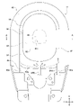
- Figure 4 is a plan view showing part of the toilet bowl of Figure 3;
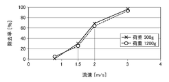
- Fig. 5 is a graph showing the relationship between the flow rate of wash water and the contaminant removal rate in a dry state;
- 4 is a graph showing the relationship between the flow rate of cleaning water and the dirt removal rate when in a wet state.
- the toilet device 10 mainly includes a toilet bowl 12 , a cleaning mechanism 16 that supplies cleaning water for cleaning the toilet bowl into a toilet bowl portion 14 of the toilet bowl 12 , and a controller 18 that controls the cleaning mechanism 16 .
- the toilet device 10 also includes, for example, a casing (not shown) mounted on the toilet bowl 12, and a toilet seat and toilet lid (not shown) arranged on the toilet bowl 12 so as to be openable and closable.
- the casing carries a plurality of devices such as sanitary washing devices for washing the private parts of the seated person.
- the cleaning mechanism 16 includes a main mechanism section 20 for executing toilet bowl cleaning and a sub-mechanism section 22 for executing a pre-cleaning operation.
- Toilet bowl cleaning refers to an operation of discharging waste in the toilet bowl 14 by supplying cleansing water into the toilet bowl 14 after the user has used the toilet.
- the pre-washing operation refers to an operation of wetting the inside of the toilet bowl portion 14 by supplying liquid before the user uses the toilet. By executing the pre-cleaning operation before the user uses the toilet, it is possible to improve the dirt removal performance during cleaning the toilet bowl.
- the main mechanism portion 20 includes at least one discharge portion 24A, 24B for discharging flushing water into the toilet bowl portion 14, a water supply channel 28 serving as a passage for water supplied from the water source 26 to the discharge portions 24A, 24B, and a water supply channel. and a first on-off valve 30 capable of opening and closing the valve 28 .
- the ejection parts 24A and 24B of this embodiment are provided in nozzles separate from the toilet bowl 12 .
- the discharge portions 24A and 24B may be provided integrally with the toilet bowl 12 as part of the toilet bowl 12 .
- the water source 26 is, for example, tap water, a tank, or the like.
- the water supply line 28 includes a common water line 28a provided with a first on-off valve 30, and a plurality of branch water lines 28b branching from the common water line 28a and communicating with the individual outlets 24A and 24B.
- the first on-off valve 30 is an electrically driven valve such as a solenoid valve or an electric valve.
- the sub-mechanism part 22 includes a sub-discharging part 32 for discharging liquid for the pre-washing operation into the toilet bowl part 14, a liquid supply path 36 serving as a path for the liquid supplied from the liquid source 34 to the sub-discharging part 32, and a second on-off valve 38 capable of opening and closing the liquid supply path 36 .
- the sub discharge part 32 of this embodiment is provided in a nozzle separate from the toilet bowl 12 .
- the sub discharge part 32 may be provided integrally with the toilet bowl 12 as part of the toilet bowl 12 .
- the liquid source 34 may be common to or separate from the water source 26 .
- the liquid used for the pre-cleaning operation in this embodiment is cleaning water.
- the liquid may be detergent, sterilized water, or the like.
- the second on-off valve 38 is an electrically driven valve like the first on-off valve 30 .
- the control unit 18 is a computer configured by a combination of CPU, ROM, and RAM.
- Components of the flushing mechanism 16 that are separate from the toilet bowl 12 for example, the on-off valves 30 and 38, the nozzles that constitute the discharge portions 24A and 24B, etc.) are mounted on the aforementioned casing.
- the cleaning mechanism 16 can perform toilet cleaning when predetermined toilet cleaning conditions are met.
- the toilet bowl cleaning condition is, for example, that the controller 18 acquires a toilet bowl cleaning command output from an operation terminal such as a controller or a mobile terminal.
- Toilet flushing is performed by the controller 18 keeping the first on-off valve 30 open for a predetermined period of time so that flushing water is discharged from the discharge units 24A and 24B.
- the cleaning mechanism 16 can perform a pre-cleaning operation when predetermined pre-cleaning conditions are met.
- the pre-cleansing condition is, for example, detection of a predetermined pre-defecation action by the user before defecation.
- the action before using the toilet is, for example, a sitting action of sitting on the toilet seat.
- the sensor is composed of, for example, a photoelectric sensor, a touch sensor, a pressure sensor, a human sensor, and the like.
- the pre-cleaning operation is performed by keeping the second on-off valve 38 open for a predetermined period of time so that cleaning water is discharged from the sub-discharging section 32 .
- the directions are the front-back direction X, the left-right direction Y, and the up-down direction Z.
- the front-rear direction X and the left-right direction Y are horizontal directions and correspond to the front, back, left, and right of a person sitting on the toilet seat in a normal posture.
- the vertical direction Z is the vertical direction.
- the toilet bowl 12 includes a toilet bowl portion 14 and an upper surface portion 40 in which an upper end opening of the toilet bowl portion 14 opens.
- the toilet bowl 14 has a bowl surface 42 and a recess 44 for receiving waste.
- the bowl surface 42 is a bowl-shaped member that opens upward.
- the concave portion 44 is a member that is provided below the bowl surface 42 and is recessed downward with respect to the bowl surface 42 .
- the bowl surface 42 and the concave portion 44 of this embodiment are integrally provided as part of the same member. Alternatively, these may be provided separately.
- the upper surface portion 40 includes a housing recess 46 provided behind the toilet bowl portion 14 .
- the accommodation recess 46 is recessed downward from the peripheral edge portion 40 a of the upper surface portion 40 at the peripheral edge of the accommodation recess 46 .
- the toilet device 10 includes a drain pipe 48 connected to the bottom of the toilet bowl portion 14 .
- An inlet 48 a of the drain pipe 48 opens into the recess 44 of the toilet bowl 14 .
- the drain line 48 of this embodiment includes a toilet drain channel 50 that forms part of the toilet bowl 12 and a drain socket 52 connected to the toilet drain channel 50 .
- the drain line 48 is connected to a drain pipe (not shown) installed in the building.
- the drain pipe 48 serves as a path for waste discharged from the toilet bowl portion 14 into the drain pipe.
- the drainage pipe line 48 includes a sealed water reservoir 56 such as a drainage trap that stores the sealed water 54 in the toilet bowl 14 .
- a part of the sealing water 54 becomes a pooled water 58 that is pooled in the toilet bowl portion 14 .
- the water surface of the pooled water 58 in a stationary state and at the highest water level that can be stored in the toilet bowl 14 is referred to as a pooled water surface 60 .
- the toilet bowl portion 14 includes a first bowl surface portion 62 and a second bowl surface portion 64 .
- the first bowl surface portion 62 is provided above the stagnant water surface 60 and below the discharge portions 24A and 24B.
- the second pot surface portion 64 is provided below the stagnant water surface 60 and above the recessed portion 44 .
- “below the ejection portions 24A and 24B” means that, when there are a plurality of ejection portions 24A and 24B, if the ejection ports 24A and 24B at the lowest position are located below the lowest position of the ejection port 24a. good.
- the discharge port 24a here refers to a portion of the discharge portions 24A and 24B from which washing water is discharged.
- the ejection port 24a of the second ejection section 24B is located at the lowest position among the first ejection section 24A and the second ejection section 24B, which will be described later. Therefore, the first bowl surface portion 62 is provided below the lowest position of the ejection port 24a of the second ejection portion 24B.
- the first bowl surface portion 62 serves as a flow path for washing water discharged from the discharge portions 24A and 24B.
- the upper edge 62a of the range of the first bowl surface portion 62 is schematically indicated by a dashed line.
- the “discharging portion” that defines the first bowl surface portion 62 is a concept excluding the jet hole that discharges a jet flow for forming a water flow that promotes the discharge of waste in the drainage pipe line 48 .
- This jet hole is formed in either the bottom of the toilet bowl 14 or the drain pipe 48 .
- This “discharging part” can also be regarded as a part that discharges cleansing water from the upper part of the toilet bowl part 14 .
- the first bowl surface portion 62 has a smooth surface portion 66 that continues upward from the stagnant water surface 60 .
- the smooth surface portion 66 continues smoothly in the vertical direction without forming an inwardly protruding convex curved surface portion.
- the smooth surface portion 66 of the present embodiment is provided over the entire area of the first pot surface portion 62 in the vertical direction Z.
- the convex curved surface portion here is assumed to be a portion that connects the shelf portion and the smooth surface portion 66 when the shelf portion is provided on the outer peripheral side portion of the bowl surface 42 , for example. This shelf has a gentler slope than the upper end of the smooth surface 66 .
- quadrant lines La1 to La3 that divide the maximum front-to-rear dimension Ax regarding the inner surface of the toilet bowl 14 into quarters, and a left-right center line Lb that bisects the maximum left-to-right dimension Ay of the toilet bowl 12 are assumed.
- the toilet bowl portion 14 has a front region 68 provided in front of the toilet bowl portion 14, a rear region 70 provided behind the toilet bowl portion 14, and a space between the front region 68 and the rear region 70 in plan view.
- a pair of lateral regions 72, 74 are provided on the left and right sides.
- the front area 68 is an area ahead of the front quadrant La1.
- the rear area 70 is the area behind the rear quadrant La3.
- the pair of side regions 72 and 74 are regions between the front and rear quadrants and regions on both sides of the left and right center line Lb.
- the pair of side regions 72 and 74 includes a right side region 72 on the right side in the horizontal direction Y and a left side region 74 on the left side in the horizontal direction Y.
- the toilet bowl portion 14 has a front half portion 80 that constitutes its front half portion and a rear half portion 82 that constitutes its rear half portion.
- the front half portion 80 is on the front side of the quadrant line La2 on the central side of the toilet bowl portion 14, and the rear half portion 82 is on the rear side of the quadrant line La2.
- the quarter line La2 can be regarded as a front-rear center line that bisects the maximum front-rear dimension Ax of the toilet bowl portion 14 .
- At least one ejection portion 24A, 24B includes a first ejection portion 24A and a second ejection portion 24B. Each figure schematically shows the ejection portions 24A and 24B.
- arrows indicate the flow direction of part of the wash water discharged from the discharge portions 24A and 24B.
- arrows indicate the flow direction of the water flow formed by the washing water discharged from the discharge portions 24A and 24B.
- the first discharge part 24 ⁇ /b>A can form a swirling water flow 76 that swirls inside the toilet bowl 14 by discharging wash water toward the right side region 72 of the toilet bowl 14 .
- the washing mechanism 16 forms a swirling water flow 76 by supplying washing water into the toilet bowl 14 .
- the swirling water flow 76 refers to a water flow that flows in at least a part of the circumferential range in the toilet bowl portion 14 in the circumferential direction.
- the swirling water flow 76 does not necessarily flow over the entire circumferential range within the toilet bowl portion 14 .
- the swirling water flow 76 may flow, for example, in a circumferential range of more than half the circumference of the toilet bowl portion 14 .
- the swirling water stream 76 of this embodiment can flow through the toilet bowl 14 so as to pass through the right side region 72 , the front region 68 , and the left side region 74 in this order.
- the second discharge part 24B can form a flowing water stream 78 that flows downward in the rear area 70 by discharging a wide width of washing water downward to the rear area 70 of the toilet bowl part 14 .
- These water streams 76 and 78 wash off the dirt in the toilet bowl 14 and then discharge the dirt through the drain pipe 48 to clean the toilet bowl.
- the secondary discharge part 32 supplies the liquid for wetting the first bowl surface part 62 of the toilet bowl part 14 into the toilet bowl part 14 .
- the manner in which the liquid is supplied from the sub-discharge portion 32 is not particularly limited.
- the sub-discharging part 32 may supply the liquid into the toilet bowl part 14 by injecting mist-like liquid.
- FIG. 2 shows the liquid ejection range Sa of the sub ejection portion 32 .
- the washing mechanism 16 is conditioned to supply washing water with a flow velocity [m/s] (hereinafter, the unit is omitted) of 1.5 or more in relation to the dirt removing ability. .
- This flow rate should be satisfied by the washing water immediately after being discharged from the discharging portions 24A and 24B.
- the toilet device 10 is preferably configured such that the flow rate of flush water at the first bowl surface portion 62 of the toilet bowl portion 14 is 1.5 or more.
- the general flow rate of washing water is 0.6 to 1.2, and the condition is to increase the flow rate. As a result, it is possible to obtain a good contaminant removal capability as described later.
- the flow velocity of the cleaning water described here may be measured using, for example, a flow meter.
- the PIV method Particle Image Velocimetry
- the PIV method is a method of inserting a marker called a tracer into the flow field and calculating the velocity of the flow field from the amount of movement of the moving marker.
- the marker and washing water may be run together, and the movement speed of the marker may be measured using a camera or the like.
- the toilet device 10 is preferably configured so that the flow velocity of the wash water on the first bowl surface portion 62 is 2.0 or higher when the first bowl surface portion 62 is in a dry state.
- the "dry state” here means that the first pot surface portion 62 is in a dry state without getting wet.
- the toilet device 10 may be configured so that the flow rate of flush water in the first bowl surface portion 62 in the dry state is 1.5 or higher.
- the dry state is satisfied, for example, when the first pot surface portion 62 is in a state where no water droplets are attached.
- the dry state may be realized, for example, by blowing air to the first bowl surface portion 62 until it is confirmed that no water droplets are attached. This may be accomplished using either actual toilet bowls 12 or samples.
- the toilet device 10 is preferably configured such that when the first bowl surface 62 is in a wet state, the flow rate of flush water on the first bowl surface 62 is 1.5 or more, more preferably 2.0 or more. should be.
- the “wet state” here means that the first bowl surface portion 62 is in a wet state due to a pre-cleaning operation or the like. As will be described later, it is possible to obtain a remarkably good dirt removing ability as compared with the case where washing water is flowed at a flow rate of 1.5 or less to the first pot surface portion 62 in a dry state.
- the toilet bowl portion 14 of the toilet bowl 12 is preferably made of a hydrophilic material from the viewpoint of keeping the first bowl surface portion 62 wet for a long period of time.
- the wet state is satisfied when, for example, the first pot surface portion 62 is at least partially wet immediately after the entire surface of the first pot surface portion 62 is wetted.
- "immediately after wetting the entire surface of the first bowl surface 62" means, for example, immediately after 30 seconds to 1 minute have passed since the entire surface of the first bowl surface 62 has been wetted.
- the wet state may be achieved by, for example, wetting the entire surface of the first pot surface portion 62 using a washing bottle.
- the wet state may be achieved by spraying the entire surface of the first pot surface portion 62 with water, or by submerging the toilet bowl 12 . These may be realized using either the actual toilet bowl 12 or a sample.
- the upper limit of the flow rate of the wash water is not particularly limited. This upper limit value may be 10.0 under the condition that the flow rate is in the range of 50 to 100 [L/min], for example.
- flow velocity conditions A position that preferably satisfies the conditions related to the flow velocity of the washing water (hereinafter referred to as flow velocity conditions) will be explained. First, the position in the circumferential direction of the toilet bowl 14 that preferably satisfies the washing conditions will be described.
- the flow velocity condition is preferably satisfied in the first bowl surface portion 62 and the rear half portion 82 where fecal matter easily adheres. As a result, stool that tends to adhere to the rear half portion 82 can be removed satisfactorily. From the relationship with such an effect, it is preferable that the flow velocity condition is satisfied at the rear of the concave portion 44 and at the first bowl surface portion 62 .
- the flow velocity condition is preferably satisfied in the first bowl surface portion 62 and the front half portion 80 where urine as waste tends to adhere. As a result, urine that tends to adhere to the front half portion 80 can be removed satisfactorily. From the relationship with such an effect, the flow velocity condition is preferably satisfied in the front of the recess 44 and in the first bowl surface portion 62 .
- the flow velocity condition may be satisfied in at least two of the front region 68 , rear region 70 , right side region 72 and left side region 74 and at the first bowl surface portion 62 .
- the two locations here may be, for example, a combination of the front region 68 and the rear region 70 or a combination of the right side region 72 and the left side region 74 .
- the flow velocity condition may be satisfied at two first bowl surface portions 62 that are continuous in the turning direction Da described below. As a result, contaminants can be satisfactorily removed over a wide area.
- the flow velocity conditions may be satisfied at the four locations 68, 70, 72, and 74 described above.
- the flow velocity condition is satisfied in two or more of the regions 68, 70, 72, and 74 that are on the water flow path of the swirling water flow 76 and that are continuous in the swirling direction Da of the swirling water flow 76.
- the right side region 72 and the front region 68 that are continuous in the turning direction Da may be filled, or the front region 68 and the left side region 74 may be filled.
- the flow velocity condition may be satisfied in three or more areas that are continuous in the swirl direction Da among these four areas. Other flow rate conditions may also be met in these four regions.
- the regions 68, 70, 72, 74 satisfy the flow velocity condition, and it is not necessary to satisfy the entire region.
- the "part” here may be, for example, 70% or more of each of the regions 68, 70, 72, 74.
- the "part” here may be a partial portion of the regions 68, 70, 72, 74 where it is difficult to remove dirt.
- the flow velocity condition may be satisfied at 70% or more of the entire regions 68 , 70 , 72 , 74 .
- the flow velocity condition is preferably satisfied in a range extending over half or more of the toilet bowl portion 14 in the circumferential direction. More preferably, the flow velocity condition is satisfied over the entire circumference.
- the circumferential direction here refers to the circumferential direction of a circle whose center is the intersection point Ca (see FIG. 5) of the quadrant line La2 on the central side of the toilet bowl 14 and the left-right center line Lb.
- the flow velocity of the wash water in the rear half portion 82 of the toilet bowl portion 14 may be faster than the flow speed of wash water in the front half portion 80 thereof.
- This condition is based on the premise that the flow velocity of the washing water in the latter half 82 is 1.5 or higher.
- the flow velocity of the washing water in the front half 80 may be 1.5 or more, or may be less than 1.5.
- the flow velocity is increased in the rear half portion 82 where feces that are difficult to remove tend to adhere, while the flow velocity in the front half portion 80 where urine that is easy to remove tends to adhere is reduced.
- the actual flow velocity is excessively increased with respect to the flow velocity required for removing contaminants. can be done without As a result, the performance required of the cleaning mechanism 16 to obtain the required contaminant removal performance can be relaxed.
- the flow velocity of the wash water in the rear half portion 82 of the toilet bowl portion 14 may be set to be equal to or lower than the flow speed of wash water in the front half portion 80 thereof.
- the vertical position of the toilet bowl 14 that preferably satisfies the flow velocity condition will be described. It is preferable that the flow velocity condition is satisfied in the vertical range including the smooth surface portion 66 in the first bowl surface portion 62 of the toilet bowl portion 14 . If the bowl surface 42 does not have a shelf portion, the flow velocity condition may be satisfied at the smooth surface portion 66 of the first bowl surface portion 62, and if the bowl surface 42 has a shelf portion, the flow rate conditions may be It is sufficient that the smooth surface portion 66 is satisfied. If there is a shelf on the pot surface 42, the flow velocity of the washing water on the smooth surface 66 below the shelf tends to decrease, making it difficult to remove dirt. Therefore, by satisfying the above-described flow rate condition in the range including the smooth surface portion 66, it becomes possible to remove the filth in a wide vertical range of the first bowl surface portion 62 satisfactorily.
- the first bowl surface portion 62 of the toilet bowl portion 14 In order to satisfy the flow velocity condition in the first bowl surface portion 62 of the toilet bowl portion 14, at least the vertical central portion of the first bowl surface portion 62 may be satisfied.
- the first cup surface portion 62 may be filled at a plurality of locations in the vertical direction, or the entire range in the vertical direction of the first cup surface portion 62 may be filled.
- the flow velocity condition may be satisfied at the second bowl surface portion 64 below the stagnant water surface 60 .
- the toilet device 10 is configured so as to satisfy the flow velocity condition at the target position.
- the shape of the toilet bowl 14 that is preferable in relation to the flow velocity conditions will be described.
- the entire area in the vertical direction of the first bowl surface portion 62 of the toilet bowl portion 14 may be configured by the smooth surface portion 66 without the convex curved surface portion. This makes it easier to satisfy the flow velocity condition of the cleaning water at the target position.
- the radius of curvature of the convex surface portion connecting the shelf portion and the smooth surface portion 66 may be increased.
- the larger the radius of curvature the more it is possible to prevent a rapid decrease in the flow velocity at the convex curved surface portion, and the easier it is to satisfy the flow velocity condition of the washing water at the target location.
- the preferred configuration of the cleaning mechanism 16 in relation to the flow velocity conditions will be described.
- two ejection portions 24A and 24B are used.
- Three or more ejection portions 24A, 24B may be used.
- the flow velocity of the cleaning water discharged from the discharge sections 24A and 24B may be increased, or the range in which the cleaning water is discharged from the discharge sections 24A and 24B may be increased.
- the flow velocity v of the cleansing water is obtained by using the volumetric flow rate Q of cleansing water passing through the outlets 24a of the outlets 24A and 24B and the cross-sectional area A of the cross section perpendicular to the axial direction of the outlets 24A and 24B. It can be represented by the formula (1). As can be seen from the formula (1), in order to increase the flow velocity v of the washing water when passing through the discharge port 24a, the cross-sectional area A of the discharge port 24a should be reduced, or the volumetric flow rate of the wash water supplied to the discharge portion Increasing Q is effective.
- nozzles when nozzles are used as the discharge parts 24A and 24B, it is preferable to shorten the distance from when the flush water leaves the nozzle until it reaches the bowl part 14 of the toilet bowl 12 as much as possible.
- the axial direction of the discharge port 24a of the nozzle and the tangential direction of the position where the wash water reaches the toilet bowl 14 should be made as close to parallel as possible. As a result, the impact when the cleansing water reaches the toilet bowl 14 can be reduced, and a drop in the flow rate of the cleansing water can be prevented.
- the swirl water flow 76 formed in the toilet bowl 14 satisfies the flow velocity condition.
- the swirling water flow 76 passing through the side regions 72, 74 and the front region 68 satisfy the flow velocity conditions.
- the number of the discharge portions 24A and 24B is reduced, and a water flow having a flow velocity of 1.5 or more is generated over a wide range of the toilet bowl portion 14. Easy to form.
- the above flow velocity conditions may be satisfied in the flowing water stream 78 formed within the toilet bowl 14 .
- a pseudo-waste 92 having the component ratio of stool was created.
- the simulated waste 92 consists of a plurality of components corresponding to moisture, food residue, intestinal bacteria, intestinal substances, and the like.
- the simulated waste 92 contains a predetermined amount of these components and resembles the properties of actual stool.
- the moisture content of the simulated waste 92 was set to 53% in order to make the properties similar to those of stool.
- the imitation dirt 92 is allowed to fall freely from a spaced position above the test piece 90, and when it adheres to the test piece 90, a predetermined maximum impact load [g] is applied. added.
- This test was conducted under a first load condition of 300 g and a second load condition of 1200 g.
- the first load condition assumes a collision load when feces adhere to the toilet bowl 14 when a user with general abdominal pressure urinates in a sitting posture on the toilet seat.
- the second load condition assumes a collision load that adheres to the toilet bowl 14 when a user with high abdominal pressure urinates under similar conditions.
- This test was conducted under conditions in which the surface of the panel was wet and dry.
- the wet state was realized by spraying water onto the test piece 90 with a sprayer.
- the dry state was realized by wiping the moisture of the test piece 90 with a cloth and blowing warm air with a dryer until the moisture was removed.
- the mass ma [g] means the mass of the pseudo dirt 92 on the test piece 90 before washing water is poured, and was set to 1.0 g here.
- the mass mb [g] is the mass of the pseudo dirt 92 remaining on the test piece 90 after the washing water has flowed.
- the contaminant removal rate is the ratio of the mass of the pseudo contaminants removed by flowing the cleaning water to the mass of the pseudo contaminants before the cleaning water is flushed, expressed as a percentage.
- the dirt removal capacity (e.g., removal rate) is much better under severe dirt conditions. 60% or more) can be obtained.
- the trend of change in the dirt removal capacity changes around the point where the flow velocity is set to 2.0.
- the flow rate is less than 2.0, the dirt removal capacity is greatly reduced.
- it is 2.0 or more it is possible to obtain a stable contaminant removal ability (for example, a removal rate of 60% or more).
- the flow rate of the cleansing water flowing through the toilet bowl 14 can be stably increased to 1.5 or higher, and the waste adhering to the toilet bowl 14 can be made stable. can be satisfactorily removed.
- the toilet bowl 12 may not have jet holes as in the embodiment, or may have jet holes.
- the cleaning mechanism 16 only needs to include at least the main mechanism section 20 for executing toilet bowl cleaning, and the sub-mechanism section 22 for executing the pre-cleaning operation is not essential.
- the main mechanism section 20 may also serve as the sub mechanism section 22 .
- the pre-cleaning operation is performed by forming either the swirling water flow 76 or the flowing water flow 78 by discharging the liquid into the toilet bowl portion 14 .
- at least one of the ejection portions 24A and 24B may also serve as the sub-ejection portion 32 .
- the pre-cleaning operation may be performed by discharging an amount of water smaller than the amount of water discharged from the discharge sections 24A and 24B during toilet flushing from the discharge sections 24A and 24B, which also serves as the sub discharge section 32.
- the number of ejection portions 24A and 24B of the cleaning mechanism 16 is not particularly limited. Although the flow velocity of the washing water can be easily increased to 1.5 or more within the desired range as the number of the discharge sections 24A and 24B is increased, the number of the discharge sections 24A and 24B may be reduced to one.
- the cleaning mechanism 16 should be configured so that at least the flow rate of the cleaning water discharged from the discharge portions 24A and 24B is 1.5 or higher. This means that it is not essential to set the flow rate of flush water in the first bowl surface portion 62 of the toilet bowl 12 to 1.5 or more. There are no particular restrictions on the specific locations in the toilet bowl portion 14 of the toilet bowl 12 where the flush water flow rate is set to 1.5 or higher. For example, in terms of the circumferential range of the toilet bowl 14, even if the flow velocity of the wash water is set to 1.5 or more in only one of the front area 68 and the rear area 70, and the flow velocity is set to less than 1.5 in other locations. good. In addition, the flow velocity of the washing water may be set to 1.5 or more only at two locations sandwiching the pooled water surface 60, and the flow velocity may be set to less than 1.5 at other locations.
- the washing mechanism 16 may form only one of the swirling water flow 76 and the flowing water flow 78 over the entire circumference of the toilet bowl 14, and the flow velocity of the formed one water flow may be 1.5 or more.
Landscapes
- Engineering & Computer Science (AREA)
- Health & Medical Sciences (AREA)
- Life Sciences & Earth Sciences (AREA)
- Hydrology & Water Resources (AREA)
- Public Health (AREA)
- Water Supply & Treatment (AREA)
- Aviation & Aerospace Engineering (AREA)
- Sanitary Device For Flush Toilet (AREA)
Abstract
便鉢部と、便鉢部に、流速を1.5[m/s]以上とする便器洗浄のための洗浄水を供給する洗浄機構と、を備える便器装置である。洗浄機構は、便鉢部に洗浄水を吐き出す吐出部を備え、便鉢部は、便鉢部の溜水面から上方かつ吐出部よりも下方に設けられる鉢面部を備え、便器装置は、鉢面部での洗浄水の流速[m/s]を1.5以上とするように構成されてもよい。
Description
本開示は、便器装置に関する。
特許文献1は、便鉢部と、便器洗浄のための洗浄水を便鉢部内に供給する洗浄機構とを備える便器装置を開示する。この便器装置は、汚物除去能力を高めるため、便鉢部に洗浄水を旋回させる旋回路部を設け、その旋回路部を流れる勢いで汚物を洗い流すように工夫を講じている。
本願発明者は、良好な汚物除去能力を得るための条件について検討を進めた。この結果、良好な汚物除去能力を得るうえで、洗浄水の流速の最適化が有効であるとの知見を得た。このような洗浄水の流速と汚物除去能力との関係で工夫を講じた技術は未だ提案されていない。
本開示の目的の1つは、良好な汚物除去能力を得ることができる便器装置を提供することにある。
本開示の便器装置は、便鉢部と、前記便鉢部に、流速[m/s]を1.5以上とする便器洗浄のための洗浄水を供給する洗浄機構と、を備える。
以下、実施形態を説明する。同一の構成要素には同一の符号を付し、重複する説明を省略する。各図面では、説明の便宜のため、適宜、構成要素を省略、拡大、縮小する。図面は符号の向きに合わせて見るものとする。
図1を参照する。便器装置10は、主に、便器12と、便器12の便鉢部14内に便器洗浄のための洗浄水を供給する洗浄機構16と、洗浄機構16を制御する制御部18と、を備える。便器装置10は、この他に、例えば、便器12上に取り付けられるケーシング(図示せず)と、便器12上に開閉可能に配置される便座及び便蓋(図示せず)とを備える。ケーシングは、着座者の局部を洗浄する衛生洗浄機器等の複数の機器を搭載する。
洗浄機構16は、便器洗浄を実行するための主機構部20と、プレ洗浄動作を実行するための副機構部22と、を備える。便器洗浄とは、ユーザの用便後において、便鉢部14内に洗浄水を供給することによって、便鉢部14内の汚物を排出する動作をいう。プレ洗浄動作とは、ユーザの用便前において、液体を供給することによって、便鉢部14内を濡らす動作をいう。ユーザの用便前にプレ洗浄動作を実行することで、便器洗浄時の汚物除去性能を高めることができる。
主機構部20は、洗浄水を便鉢部14内に吐き出す少なくとも一つの吐出部24A、24Bと、水源26から吐出部24A、24Bに供給される水の通り道となる給水路28と、給水路28を開閉可能な第1開閉弁30と、を備える。
本実施形態の吐出部24A、24Bは、便器12とは別体のノズルに設けられる。吐出部24A、24Bは、この他にも、便器12の一部として便器12に一体に設けられてもよい。水源26は、例えば、上水道、タンク等である。給水路28は、第1開閉弁30が設けられる共通水路28aと、共通水路28aから分岐して個別の吐出部24A、24Bに通じる複数の分岐水路28bとを備える。第1開閉弁30は、電磁弁、電動弁等の電気駆動弁である。
副機構部22は、プレ洗浄動作のための液体を便鉢部14内に吐き出す副吐出部32と、液源34から副吐出部32に供給される液体の通り道となる給液路36と、給液路36を開閉可能な第2開閉弁38と、を備える。
本実施形態の副吐出部32は、便器12とは別体のノズルに設けられる。副吐出部32は、この他にも、便器12の一部として便器12に一体に設けられてもよい。液源34は、水源26と共通及び別体の何れでもよい。本実施形態においてプレ洗浄動作に用いられる液体は洗浄水である。この他にも、液体は洗剤、除菌水等でもよい。第2開閉弁38は、第1開閉弁30と同様に電気駆動弁である。
制御部18は、CPU、ROM、RAMの組み合わせにより構成されるコンピュータである。洗浄機構16における便器12とは別体の構成要素(例えば、開閉弁30、38、吐出部24A、24Bを構成するノズル等)は、前述のケーシングに搭載される。
洗浄機構16は、制御部18による制御のもと、所定の便器洗浄条件を満たしたときに便器洗浄を実行可能である。便器洗浄条件は、例えば、コントローラ、携帯端末等の操作端末から出力される便器洗浄指令を制御部18が取得することである。便器洗浄は、制御部18によって、予め定められた時間の間、吐出部24A、24Bから洗浄水が吐き出されるように第1開閉弁30を開状態に維持することで実行される。
洗浄機構16は、制御部18による制御のもと、所定のプレ洗浄条件を満たしたときにプレ洗浄動作を実行可能である。プレ洗浄条件は、例えば、センサによってユーザが用便前に行う所定の用便前動作を検出することである。用便前動作は、例えば、便座に着座する着座動作である。センサは、例えば、光電センサ、タッチセンサ、感圧センサ、人感センサ等によって構成される。プレ洗浄動作は、予め定められた時間の間、副吐出部32から洗浄水が吐き出されるように第2開閉弁38を開状態に維持することで実行される。
図2~図4を参照する。以下、互いに直交する三つの方向を用いて説明する。この方向とは、前後方向X、左右方向Y及び上下方向Zである。前後方向X、左右方向Yは水平方向であり、便座に通常の姿勢で座る着座者の前後左右と対応する。上下方向Zは鉛直方向である。
便器12は、便鉢部14と、便鉢部14の上端開口部が開口する上面部40と、を備える。便鉢部14は、汚物を受けるための鉢面42と凹部44を備える。鉢面42は上方に開口する椀状部材である。凹部44は、鉢面42の下方に設けられ、鉢面42に対して下向きに凹む部材である。本実施形態の鉢面42と凹部44は同じ部材の一部として一体に設けられる。この他にも、これらは別体に設けられてもよい。上面部40は、便鉢部14に対して後方に設けられる収容凹部46を備える。収容凹部46は、収容凹部46の周縁にある上面部40の周縁部40aよりも下向きに凹んでいる。洗浄機構16の一部の構成要素(吐出部24A、24B等)は収容凹部46に収容される。
便器装置10は、便鉢部14の底部に接続される排水管路48を備える。排水管路48の入口48aは便鉢部14の凹部44に開口する。本実施形態の排水管路48は、便器12の一部となる便器排水路50と、便器排水路50に接続される排水ソケット52とを備える。排水管路48は、建物に設置される排水管(不図示)に接続される。排水管路48は、便鉢部14内から排水管に排出される汚物の通り道となる。排水管路48は、便鉢部14内に封水54を貯留する排水トラップ等の封水貯留部56を備える。封水54の一部は便鉢部14内に溜められる溜め水58となる。以下、静止した状態にある溜め水58の水面であって、便鉢部14内に溜めることができる最高水位にある溜め水58の水面を溜水面60という。
便鉢部14は、第1鉢面部62と、第2鉢面部64とを備える。第1鉢面部62は溜水面60から上方かつ吐出部24A、24Bよりも下方に設けられる。第2鉢面部64は、溜水面60よりも下方かつ凹部44よりも上方に設けられる。ここでの「吐出部24A、24Bよりも下方」とは、複数の吐出部24A、24Bがある場合、最も低い位置にある吐出部24A、24Bの吐出口24aの最低位置よりも下方にあればよい。ここでの吐出口24aとは、吐出部24A、24Bの洗浄水を吐き出す箇所をいう。本実施形態では、後述する第1吐出部24A、第2吐出部24Bのなかで、第2吐出部24Bの吐出口24aが最も低い位置にある。よって、第1鉢面部62は、第2吐出部24Bの吐出口24aの最低位置よりも下方に設けられることになる。第1鉢面部62は、吐出部24A、24Bから吐き出された洗浄水の通水経路となる。各図では第1鉢面部62の範囲の上端縁62aを模式的に一点鎖線で示す。この第1鉢面部62を定める「吐出部」は、排水管路48に汚物の排出を促進する水流を形成するための噴流を吐き出すジェット孔を除く概念である。このジェット孔は、便鉢部14の底部及び排水管路48の何れかに形成される。この「吐出部」は、便鉢部14の上部において洗浄水を吐き出すものとも捉えることができる。
第1鉢面部62は、溜水面60から上方に連続する滑面部66を備える。滑面部66は、内向きに突き出る凸曲面部を形成することなく滑らかに上下方向に連続する。本実施形態の滑面部66は、第1鉢面部62の上下方向Zの全域に設けられる。ここでの凸曲面部とは、例えば、鉢面42の外周側部分に棚部が設けられる場合に、棚部と滑面部66を繋ぐ箇所を想定している。この棚部は、滑面部66の上端部より緩やかな勾配を持つ。
図5を参照する。ここでは、便鉢部14の内面に関する最大前後寸法Axを四等分する四等分線La1~La3と、便器12の最大左右寸法Ayを二等分する左右中心線Lbとを想定する。便鉢部14は、平面視において、便鉢部14の前方に設けられる前方領域68と、便鉢部14の後方に設けられる後方領域70と、前方領域68と後方領域70の間に設けられる左右で一対の側方領域72、74と、を備える。前方領域68は、前側の四等分線La1から前方の領域である。後方領域70は、後側の四等分線La3から後方の領域である。一対の側方領域72、74は、前後の四等分線の間の領域で、かつ、左右中心線Lbに対して左右両側の領域である。一対の側方領域72、74は、左右方向Yの右側にある右側方領域72と、左右方向Yの左側にある左側方領域74とを含む。この他に、便鉢部14は、その前方半分部分を構成する前半部80と、その後方半分部分を構成する後半部82とを備える。前半部80は、便鉢部14の中央側の四等分線La2よりも前側にあり、後半部82は、その四等分線La2よりも後側にある。四等分線La2は、便鉢部14の最大前後寸法Axを二等分する前後中心線として捉えることができる。
図2~図5を参照する。少なくとも一つの吐出部24A、24Bは、第1吐出部24Aと、第2吐出部24Bとを含む。各図では、吐出部24A、24Bを模式的に示す。図2~図4では、吐出部24A、24Bから吐き出される洗浄水の一部に関する流れ方向に矢印を付して示す。図5では、吐出部24A、24Bから吐き出される洗浄水によって形成される水流の流れ方向に矢印を付して示す。第1吐出部24Aは、便鉢部14の右側方領域72に向けて洗浄水を吐き出すことによって、便鉢部14内を旋回する旋回水流76を形成できる。洗浄機構16は、便鉢部14内に洗浄水を供給することによって旋回水流76を形成することになる。旋回水流76は、便鉢部14内の少なくとも一部の周方向範囲を周方向に流れる水流をいう。旋回水流76は、便鉢部14内の周方向全範囲を流れることを必須とするものではない。旋回水流76は、例えば、便鉢部14内の半周以上の周方向範囲を流れてもよい。本実施形態の旋回水流76は、右側方領域72、前方領域68、左側方領域74を順に経由するように便鉢部14内を流れることができる。第2吐出部24Bは、便鉢部14の後方領域70に幅広な洗浄水を下向きに吐き出すことによって、その後方領域70を下向きに流れる流下水流78を形成できる。これらの水流76、78によって、便鉢部14内の汚物を洗い落としたうえで、排水管路48を通して汚物を排出する便器洗浄がなされる。
副吐出部32は、便鉢部14の第1鉢面部62を濡らすための液体を便鉢部14内に供給する。副吐出部32の液体の供給態様は特に限定されない。例えば、副吐出部32は、ミスト状の液体を噴射することで便鉢部14内に液体を供給してもよい。図2では、副吐出部32による液体の噴射範囲Saを示す。
洗浄機構16は、汚物除去能力との関係で、流速[m/s](以下、単位を省略する)を1.5以上とする洗浄水を便鉢部14内に供給することを条件としている。この流速は、吐出部24A、24Bから吐き出された直後の洗浄水において満たされていればよい。便器装置10は、好ましくは、便鉢部14の第1鉢面部62での洗浄水の流速を1.5以上とするように構成される。一般的な洗浄水の流速は0.6~1.2であり、それより大きい流速にすることを条件としていることになる。これにより、後述のように良好な汚物除去能力を得ることができる。ここで説明する洗浄水の流速は、例えば、流速計を用いて測定すればよい。この他にも、一般的な測定方法として、PIV法(Particle Image Velocimetry,画像粒子測定法)で測定してもよい。PIV法は、流れ場にトレーサーと呼ばれるマーカーを挿入し、移動するマーカーの移動量から流れ場の速度を算出する方法である。PIV法に従い、マーカーと洗浄水を一緒に流し、カメラ等を用いてマーカーの移動スピードを計測してもよい。
便器装置10は、好ましくは、第1鉢面部62が乾燥状態にあるとき、その第1鉢面部62での洗浄水の流速を2.0以上とするように構成されるとよい。ここでの「乾燥状態」とは、第1鉢面部62が濡れずに乾燥した状態にあることをいう。これにより、後述のように、洗浄水の流速を1.5以下にする場合と比べて、格段に良好な汚物除去能力を得ることができる。便器装置10は、乾燥状態にある第1鉢面部62での洗浄水の流速を1.5以上とするように構成されても勿論よい。
乾燥状態は、例えば、第1鉢面部62に水滴が付いていない状態にあるときに満たされる。乾燥状態は、例えば、水滴が付いていない状態になることを確認できるまで、第1鉢面部62にエアブローを行うことで実現してもよい。これは、便器12の現物及びサンプルのいずれを用いて実現してもよい。
便器装置10は、好ましくは、第1鉢面部62が濡れ状態にあるとき、その第1鉢面部62での洗浄水の流速を1.5以上、さらに好ましくは2.0以上とするように構成されるとよい。ここでの「濡れ状態」とは、第1鉢面部62がプレ洗浄動作等によって濡れた状態にあることをいう。これにより、後述のように、乾燥状態にある第1鉢面部62に1.5以下の流速の洗浄水を流す場合と比べ、格段に良好な汚物除去能力を得ることができる。便器12の便鉢部14は、第1鉢面部62を濡れ状態に長期間に亘って維持する観点から、親水性を持つ素材によって構成されると好ましい。
濡れ状態は、例えば、第1鉢面部62の全面を濡らした直後において、第1鉢面部62が少なくとも部分的に濡れた状態にあるときに満たされる。ここでの「第1鉢面部62の全面を濡らした直後」とは、例えば、第1鉢面部62の全面を濡らしてから30秒~1分が経過した直後をいう。濡れ状態は、例えば、洗瓶を用いて第1鉢面部62の全面を濡らすことによって実現してもよい。この他にも、濡れ状態は、第1鉢面部62の全面に対して霧吹きすることによって実現してもよいし、便器12を浸漬することによって実現してもよい。これらは、便器12の現物及びサンプルのいずれを用いて実現してもよい。
洗浄水の流速の上限値は特に限定されない。この上限値は、例えば、流量を50~100[L/min]の範囲にした条件のもと、10.0となってもよい。
以上の洗浄水の流速に関する条件(以下、流速条件という)を満たすことが好ましい位置を説明する。まず、洗浄条件を満たすことが望ましい便鉢部14の周方向での位置を説明する。
流速条件は、好ましくは、汚物としての大便の付着し易い第1鉢面部62かつ後半部82において満たされるとよい。これにより、その後半部82に付着し易い大便を良好に除去できる。このような効果との関係から、流速条件は、凹部44よりも後方かつ第1鉢面部62において満たされるとよい。
流速条件は、好ましくは、汚物としての小便の付着し易い第1鉢面部62かつ前半部80において満たされるとよい。これにより、その前半部80に付着し易い小便を良好に除去できる。このような効果との関係から、流速条件は、好ましくは、凹部44よりも前方かつ第1鉢面部62において満たされるとよい。
流速条件は、前方領域68、後方領域70、右側方領域72及び左側方領域74のうちの少なくとも二箇所かつ第1鉢面部62で満たされてもよい。ここでの二箇所とは、例えば、前方領域68と後方領域70の組み合わせでもよいし、右側方領域72と左側方領域74の組み合わせでもよい。この他にも、流速条件は、次に説明する旋回方向Daに連続する二箇所かつ第1鉢面部62で満たされてもよい。これにより、広い範囲で汚物を良好に除去できる。
流速条件は、前述の各領域68、70、72、74の四箇所で満たされていてもよい。
流速条件は、各領域68、70、72、74のうちの、旋回水流76の通水経路上にある領域であって、旋回水流76の旋回方向Daに連続する二つ以上の領域において満たされていてもよい。例えば、旋回方向Daに連続する右側方領域72、前方領域68において満たされていてもよいし、前方領域68、左側方領域74において満たされてもよい。流速条件は、さらに好ましくは、これら四つの領域のうち旋回方向Daに連続する三つ以上の領域において満たされてもよい。この他にも、流速条件は、これら四つの領域において満たされてもよい。
ここまで説明した周方向での位置に関する条件を満たすうえでは、その領域68、70、72、74の少なくとも一部において流速条件を満たしていればよく、その全域において満たす必要はない。ここでの「一部」は、例えば、その領域68、70、72、74それぞれの70%以上の箇所でもよい。この他にも、ここでの「一部」とは、その領域68、70、72、74のなかで、汚物を除去し難い部分的な箇所であってもよい。この他にも、流速条件は、各領域68、70、72、74の全域に対して70%以上の箇所において満たされていてもよい。
流速条件は、好ましくは、便鉢部14の周方向の半周以上に亘る範囲で満たされているとよい。流速条件は、さらに好ましくは、周方向の全周に亘る範囲で満たされているとよい。ここでの周方向とは、便鉢部14の中央側の四等分線La2と左右中心線Lbの交点Ca(図5参照)を中心とする円の円周方向をいう。
この他にも、便鉢部14の後半部82での洗浄水の流速を、その前半部80での洗浄水の流速よりも速くしてもよい。この条件は、後半部82において洗浄水の流速を1.5以上とすることを前提としている。この条件を満たすうえで、前半部80での洗浄水の流速を1.5以上にしてもよいし、その流速を1.5未満にしてもよい。これにより、除去し難い大便の付着し易い後半部82での流速を速くしつつ、除去し易い小便の付着し易い前半部80での流速を遅くすることになる。つまり、前半部80での洗浄水の流速を後半部82での洗浄水の流速より速くする場合と比べ、前半部80において、汚物除去に要求される流速に対して実際の流速を過剰に大きくせずに済む。ひいては、所要の汚物除去性能を得るために洗浄機構16に要求される性能を緩和することができる。この他にも、便鉢部14の後半部82での洗浄水の流速を、その前半部80での洗浄水の流速以下にしてもよい。
次に、流速条件を満たすことが望ましい便鉢部14の上下方向での位置を説明する。流速条件は、便鉢部14の第1鉢面部62において、その滑面部66を含む上下方向範囲で満たされていると好ましい。流速条件は、鉢面42に棚部がない場合、第1鉢面部62の滑面部66において満たされていればよく、鉢面42に棚部がある場合、第1鉢面部62の棚部及び滑面部66において満たされていればよいということである。鉢面42に棚部がある場合、棚部よりも下方にある滑面部66での洗浄水の流速が低下する傾向にあり、汚物を除去し難い傾向にある。よって、滑面部66を含む範囲で前述の流速条件が満たされることで、第1鉢面部62の広い上下方向範囲にある汚物を良好に除去できるようになる。
便鉢部14の第1鉢面部62において流速条件を満たすうえで、少なくとも第1鉢面部62の上下方向の中央部において満たされていてもよい。この他にも、第1鉢面部62において上下方向の複数箇所で満たされていてもよいし、第1鉢面部62の上下方向の全範囲で満たされていてもよい。この他にも、流速条件は、溜水面60よりも下側にある第2鉢面部64において満たされていてもよい。
ここまで述べた目的とする位置で流速条件を満たすうえでは、(1)便鉢部14の形状、(2)洗浄機構16の構成の何れかを調整すればよい。いずれにしても、目的とする位置で流速条件を満たすように便器装置10が構成されていればよいということである。
まず、流速条件との関係で好ましい便鉢部14の形状に関して説明する。便鉢部14において洗浄水の通水経路上に凸曲面部のような急激に曲率の変化する箇所があると、そこで流速が小さくなってしまう。よって、本実施形態のように、便鉢部14の第1鉢面部62の上下方向の全域を凸曲面部のない滑面部66によって構成してもよい。これにより、目的とする位置で洗浄水の流速条件を満たし易くなる。
この他に、便鉢部14の第1鉢面部62において棚部のある形状を採用した場合、棚部と滑面部66を繋ぐ凸曲面部の曲率半径を大きくしてもよい。この曲率半径を大きくするほど、凸曲面部での急激な流速の低下を防ぐことができ、目的とする箇所で洗浄水の流速条件を満たし易くなる。
次に、流速条件との関係で好ましい洗浄機構16の構成を説明する。目的とする位置で洗浄水の流速条件を満たすうえでは、その目的とする範囲が広くなるほど、吐出部24A、24Bの数を増やすとよい。本実施形態では、二つの吐出部24A、24Bを用いている。三つ以上の吐出部24A、24Bを用いてもよい。
この他にも、目的とする範囲が広くなるほど、吐出部24A、24Bから吐き出される洗浄水の流速を大きくしたり、吐出部24A、24Bから洗浄水が吐き出される範囲を大きくしたりしてもよい。
洗浄水の流速vは、吐出部24A、24Bの吐出口24aを通り抜けるときの、洗浄水の体積流量Qと、吐出口24aの軸線方向に直交する断面の断面積Aとを用いて、次の式(1)で表すことができる。式(1)から分かるように、吐出口24aを通り抜けるときの洗浄水の流速vを大きくするうえでは、吐出口24aの断面積Aを小さくするか、吐出部に供給される洗浄水の体積流量Qを大きくすることが有効となる。洗浄水の体積流量Qを大きくするうえでは、給水路28上に蓄圧器、ポンプ等の加圧機構を設け、加圧機構によって加圧した状態の洗浄水を、給水路28を通して供給することが有効となる。
v=Q/A ・・・(1)
v=Q/A ・・・(1)
この他にも、吐出部24A、24Bとしてノズルを用いる場合、洗浄水がノズルを離れてから便器12の便鉢部14に到達するまでの距離をできるだけ短くするとよい。この他にも、ノズルの吐出口24aの軸線方向と洗浄水が便鉢部14に到達する位置の接線方向とをできるだけ平行に近づけるとよい。これにより、洗浄水が便鉢部14に到達する時の衝撃を小さくでき、洗浄水の流速の低下を防止できる。
次に、以上の流速条件を満たすことが好ましい水流の種類に関して説明する。流速条件は、便鉢部14内において形成される旋回水流76において満たされると好ましい。本実施形態では、側方領域72、74、前方領域68を通る旋回水流76に関して流速条件を満たすと好ましいということである。これにより、便鉢部14内の全域において流下水流78のみを形成する場合と比べ、吐出部24A、24Bの個数を減らしつつ、便鉢部14の広範囲で流速を1.5以上とする水流を容易に形成できる。
この他にも、以上の流速条件は、便鉢部14内において形成される流下水流78において満たされてもよい。本実施形態では、後方領域70を通る流下水流78に関して流速条件を満たすと好ましいということである。
次に、以上の流速条件と汚物除去能力との関係を見出すために行った試験を説明する。この試験では、図6に示すような、平板状のテストピース90を作成し、その表面に大便を模した疑似汚物92を付着させた。このテストピース90上に洗浄水94を流すことで、テストピース90上に付着した疑似汚物92を除去することとした。この試験は、テストピース90上の疑似汚物92に当たるときの洗浄水の流速を0.8、1.5、2.0、3.0に変えた条件のもとで行った。
腸内環境系の学術分野では、いわゆるブリストルスケールによって、大便に関して複数種類に分類されることが知られる。この大便の種類とは、(1)コロコロ便(タイプ1)、(2)硬い便(タイプ2)(3)やや硬い便(タイプ3)、(4)普通便(タイプ4)、(5)やや軟らかい便(タイプ5)、(6)泥状便(タイプ6)、(7)水様便(タイプ7)である。ここで分類のために付した番号が小さくなるほど、大便の水分成分が小さくなり、大便が硬くなり、さらには、洗浄水による汚物の除去が困難となる。つまり、タイプ1のコロコロ便が最も洗浄水による汚物の除去が困難となる。この試験では、最も厳しい汚物条件下での汚物除去能力を評価するため、コロコロ便の成分比率を持つ疑似汚物92を用いた。ここでは、コロコロ便の成分比率を持つ疑似汚物92を作成した。疑似汚物92は、水分、食物残渣、腸内細菌、腸内物質などに相当する複数の成分からなる。疑似汚物92は、これらの成分を所定量含み、実際の便の性状に類似させている。この試験では、コロコロ便の性状に類似させるため、疑似汚物92の水分率を53%とした。
テストピース90上に疑似汚物92を付着させるうえでは、テストピース90の上方において間隔を空けた位置から疑似汚物92を自由落下させ、テストピース90への付着時に所定の最大衝突荷重[g]が付加されるようにした。この試験は、この最大衝突荷重が300gとなる第1荷重条件と、1200gとなる第2荷重条件とのもとで行った。第1荷重条件は、一般的な腹圧のユーザが便座上で座位姿勢にある状態のもと用便する場合に、便鉢部14に大便が付着するときの衝突荷重を想定したものである。第2荷重条件は、高腹圧のユーザが同様の条件で用便するときに、便鉢部14に付着するときの衝突荷重を想定したものである。
この試験は、パネルの表面を濡れ状態、乾燥状態のそれぞれの状態にした条件下で行った。濡れ状態は、テストピース90に霧吹きで水を吹き付けることにより実現した。乾燥状態は、布でテストピース90の水分を拭き取り、水分を除去できるまでドライヤーで温風を当てることにより実現した。
この他の以下の条件は、他の条件によらず同じとした。
・テストピース90上に疑似汚物92を付着させてから洗浄水を流すまでの放置時間:1[min]
・洗浄水を吐き出す吐水時間:2.2[s]
・疑似汚物92に当たるときの洗浄水94の厚み:2.0[mm]
・温度:25[℃]
・湿度:70[%]
・テストピース90の素材:陶器
・テストピース90上に疑似汚物92を付着させてから洗浄水を流すまでの放置時間:1[min]
・洗浄水を吐き出す吐水時間:2.2[s]
・疑似汚物92に当たるときの洗浄水94の厚み:2.0[mm]
・温度:25[℃]
・湿度:70[%]
・テストピース90の素材:陶器
この試験では、汚物除去能力を評価するため、次の式(2)によって表される汚物除去率を算出した。質量ma[g]は、洗浄水を流す前にテストピース90上にある疑似汚物92の質量をいい、ここでは1.0gとした。質量mb[g]は、洗浄水を流した後にテストピース90上に残る疑似汚物92の質量をいう。汚物除去率は、洗浄水を流す前の疑似汚物の質量に対する、洗浄水を流すことによって除去された疑似汚物の質量の割合を百分率で表したものとなる。汚物除去能力を評価するにあたっては、同一の試験条件のもとで5回の試験を行って得られた汚物除去率に関する測定値の平均値を評価対象とした。
汚物除去率={1-(mb/ma)}×100・・・(2)
汚物除去率={1-(mb/ma)}×100・・・(2)
以上の試験結果を説明する。図7を参照する。乾燥状態にあるとき、流速を1.5以上にしたとき、洗浄水の流速が0.8程度のときと比べて、厳しい汚物条件下において、良好な汚物除去能力(例えば、除去率で20%以上)を得ることができることを把握できる。この他に、流速を1.5以上にしたとき、流速を0.8以上1.5未満にした場合と比べ、流速の増加に伴う汚物除去能力の上がり代を大きくできることを把握できる。
乾燥状態にあるとき、流速を2.0以上にしたとき、洗浄水の流速が0.8程度のときと比べて、厳しい汚物条件下において、格段に良好な汚物除去能力(例えば、除去率で60%以上)を得ることができることを把握できる。この他に、乾燥状態にあるとき、流速を2.0とする付近を境として汚物除去能力の変化傾向が変化していることを把握できる。流速が2.0未満になると汚物除去能力が大きく減少する。これに対して、2.0以上であれば、安定した汚物除去能力(例えば、除去率で60%以上)を得ることができる。
図8を参照する。濡れ状態にあるとき、流速を1.5以上にしたとき、洗浄水の流速が0.8程度のときと比べて、厳しい汚物条件下において、良好な汚物除去能力(例えば、除去率で70%以上)を得ることができることを把握できる。濡れ状態にあるとき、流速を2.0以上にしたとき、厳しい汚物条件下において、さらに良好な汚物除去能力(例えば、除去率で80%以上)を得ることができることを把握できる。この他に、図7、図8に示すように、洗浄水の流速が0.8程度のとき、濡れ状態及び乾燥状態のいずれにあるときも同程度の汚物除去能力(例えば、除去率で20%未満)となる。これに対して、濡れ状態にあるとき、流速を1.5とする付近で、乾燥状態にあるときと比べて、流速の増大に伴う汚物除去能力の上がり代が大きく向上している。ひいては、濡れ状態にあるとき、乾燥状態にあるときと比べ、流速を1.5以上にすることで、格段に良好な汚物除去能力を得られることを把握できる。
この他に、濡れ状態にあるとき、流速を1.5~2.0とする付近を境として汚物除去能力の変化傾向が大きく変化していることを把握できる。流速が1.5未満になると汚物除去能力が急激に減少するものの、1.5~2.0の範囲以上であれば、安定した汚物除去能力(例えば、除去率で70%以上)を得ることができる。
この他に、濡れ状態及び乾燥状態の何れにあるときも、流速を1.5以上にすることで、一般的な大きさの流速(0.8程度)にする場合と比べて、良好な汚物除去能力を得ることができることを把握できる。この条件を満たす洗浄水を吐出部24A、24Bから吐き出すことで、便鉢部14内を流れる洗浄水の流速を安定して1.5以上にすることができ、便鉢部14に付着する汚物を良好に除去できることになる。
各構成要素の他の変形形態を説明する。
便器12は、実施形態のように、ジェット孔を備えていなくともよいし、ジェット孔を備えていてもよい。
洗浄機構16は、少なくとも便器洗浄を実行するための主機構部20を備えていればよく、プレ洗浄動作を実行するための副機構部22は必須とはならない。この他に、主機構部20は、副機構部22を兼ねていてもよい。これは、便鉢部14内に液体を吐き出すことによって旋回水流76及び流下水流78の何れかを形成することで、プレ洗浄動作を実行することを想定している。少なくとも一つの吐出部24A、24Bは副吐出部32を兼ねていてもよいともいえる。この場合、プレ洗浄動作は、便器洗浄時に吐出部24A、24Bから吐き出される水量よりも少ない水量を、副吐出部32を兼ねる吐出部24A、24Bから吐き出すことによって実行してもよい。
洗浄機構16の吐出部24A、24Bの個数は特に限定されない。吐出部24A、24Bの個数を増やすほど目的とする範囲で洗浄水の流速を1.5以上にすることを容易に実現できるものの、吐出部24A、24Bの個数を一つのみとしてもよい。
洗浄機構16は、少なくとも、吐出部24A、24Bから吐き出される洗浄水の流速を1.5以上にするように構成されていればよい。便器12の第1鉢面部62における洗浄水の流速を1.5以上にすることは必須ではないということである。便器12の便鉢部14において洗浄水の流速を1.5以上にする具体的な箇所は特に限定されない。たとえば、便鉢部14の周方向範囲でいえば、前方領域68及び後方領域70のうちの一方のみにおいて洗浄水の流速を1.5以上とし、他の箇所では流速を1.5未満としてもよい。この他にも、溜水面60を挟んだ二箇所においてのみ洗浄水の流速を1.5以上とし、他の箇所では流速を1.5未満としてもよい。
洗浄機構16は、便鉢部14の全周に亘る範囲で旋回水流76及び流下水流78の一方のみを形成し、その形成した一方の水流の流速を1.5以上としてもよい。
以上の実施形態及び変形形態は例示である。これらを抽象化した技術的思想は、実施形態及び変形形態の内容に限定的に解釈されるべきではない。実施形態及び変形形態の内容は、構成要素の変更、追加、削除等の多くの設計変更が可能である。前述の実施形態では、このような設計変更が可能な内容に関して、「実施形態」との表記を付して強調している。しかしながら、そのような表記のない内容でも設計変更が許容される。図面の断面に付したハッチングは、ハッチングを付した対象の材質を限定するものではない。
10…便器装置、12…便器、14…便鉢部、16…洗浄機構、24A、24B…吐出部、60…溜水面、62…第1鉢面部(鉢面部)、68…前方領域、70…後方領域、72…右側方領域、74…左側方領域、76…旋回水流、80…前半部、82…後半部。
Claims (9)
- 便鉢部と、
前記便鉢部に、流速[m/s]を1.5以上とする便器洗浄のための洗浄水を供給する洗浄機構と、を備える便器装置。 - 前記洗浄機構は、前記便鉢部に前記洗浄水を吐き出す吐出部を備え、
前記便鉢部は、前記便鉢部の溜水面から上方かつ前記吐出部よりも下方に設けられる鉢面部を備え、
前記便器装置は、前記鉢面部での前記洗浄水の流速[m/s]を1.5以上とするように構成される請求項1に記載の便器装置。 - 前記便器装置は、前記便鉢部の後半部かつ前記鉢面部での前記洗浄水の流速[m/s]を1.5以上とするように構成される請求項2に記載の便器装置。
- 前記便器装置は、前記便鉢部の前半部かつ前記鉢面部での前記洗浄水の流速[m/s]を1.5以上とするように構成される請求項2から3のいずれか1項に記載の便器装置。
- 前記便器装置は、前記便鉢部の前方領域、後方領域、右側方領域及び左側方領域のうちの少なくとも二箇所かつ前記鉢面部での前記洗浄水の流速[m/s]を1.5以上とするように構成される請求項2から4のいずれか1項に記載の便器装置。
- 前記便器装置は、乾燥状態にある前記鉢面部での前記洗浄水の流速[m/s]を2.0以上とするように構成される請求項2から5のいずれか1項に記載の便器装置。
- 前記便器装置は、濡れ状態にある前記鉢面部での前記洗浄水の流速[m/s]を1.5以上とするように構成される請求項2から6のいずれか1項に記載の便器装置。
- 前記洗浄機構は、前記便鉢部内に前記洗浄水を供給することによって旋回水流を形成し、
前記便器装置は、前記旋回水流の流速[m/s]を1.5以上とするように構成される請求項1から7のいずれか1項に記載の便器装置。 - 前記便器装置は、前記便鉢部の後半部での洗浄水の流速を、前記便鉢部の前半部の流速よりも速くするように構成される請求項1から8のいずれか1項に便器装置。
Priority Applications (1)
| Application Number | Priority Date | Filing Date | Title |
|---|---|---|---|
| CN202180092575.9A CN116917588B (zh) | 2021-03-23 | 2021-12-09 | 便器装置 |
Applications Claiming Priority (2)
| Application Number | Priority Date | Filing Date | Title |
|---|---|---|---|
| JP2021049187A JP2022147788A (ja) | 2021-03-23 | 2021-03-23 | 便器装置 |
| JP2021-049187 | 2021-03-23 |
Publications (1)
| Publication Number | Publication Date |
|---|---|
| WO2022201659A1 true WO2022201659A1 (ja) | 2022-09-29 |
Family
ID=83395323
Family Applications (1)
| Application Number | Title | Priority Date | Filing Date |
|---|---|---|---|
| PCT/JP2021/045323 Ceased WO2022201659A1 (ja) | 2021-03-23 | 2021-12-09 | 便器装置 |
Country Status (3)
| Country | Link |
|---|---|
| JP (1) | JP2022147788A (ja) |
| CN (1) | CN116917588B (ja) |
| WO (1) | WO2022201659A1 (ja) |
Citations (2)
| Publication number | Priority date | Publication date | Assignee | Title |
|---|---|---|---|---|
| JP2008280672A (ja) * | 2007-05-08 | 2008-11-20 | Matsushita Electric Ind Co Ltd | 衛生洗浄装置 |
| JP2010265693A (ja) * | 2009-05-15 | 2010-11-25 | Panasonic Electric Works Co Ltd | 便器 |
Family Cites Families (17)
| Publication number | Priority date | Publication date | Assignee | Title |
|---|---|---|---|---|
| JPH0679876U (ja) * | 1993-04-20 | 1994-11-08 | 株式会社イナックス | 補助タンクを用いたサイホン便器 |
| JPH08302797A (ja) * | 1995-04-28 | 1996-11-19 | Inax Corp | サイホンジェット式便器の洗浄方法 |
| JP2001140323A (ja) * | 1998-04-08 | 2001-05-22 | Toto Ltd | 人体洗浄装置 |
| JP2000074260A (ja) * | 1998-09-01 | 2000-03-14 | Sekisui Chem Co Ltd | 住居内の排水用配管構造 |
| JP2002294838A (ja) * | 2001-03-29 | 2002-10-09 | Toto Ltd | 水洗式大便器 |
| US8142572B2 (en) * | 2005-08-01 | 2012-03-27 | Lixil Corporation | Lavatory pan washing apparatus and washing method |
| JP5405729B2 (ja) * | 2007-03-12 | 2014-02-05 | パナソニック株式会社 | 便座装置 |
| KR101215765B1 (ko) * | 2007-09-28 | 2012-12-26 | 파나소닉 주식회사 | 위생 세정 장치 |
| JP5461781B2 (ja) * | 2008-03-11 | 2014-04-02 | パナソニック株式会社 | 衛生洗浄装置 |
| JP5117261B2 (ja) * | 2008-04-07 | 2013-01-16 | 株式会社Lixil | 水洗式便器 |
| JP5919466B2 (ja) * | 2012-05-11 | 2016-05-18 | パナソニックIpマネジメント株式会社 | 衛生洗浄装置 |
| WO2015075902A1 (ja) * | 2013-11-21 | 2015-05-28 | 日本曹達株式会社 | トイレ用洗浄剤容器 |
| JP6607341B2 (ja) * | 2015-01-20 | 2019-11-20 | Toto株式会社 | 小便器 |
| JP6956943B2 (ja) * | 2016-09-14 | 2021-11-02 | Toto株式会社 | 水洗大便器 |
| WO2019146556A1 (ja) * | 2018-01-24 | 2019-08-01 | 日本曹達株式会社 | 薬剤保持具及び薬剤との洗浄セット |
| JP7212303B2 (ja) * | 2018-09-25 | 2023-01-25 | Toto株式会社 | 水洗大便器 |
| CN110924497A (zh) * | 2019-11-12 | 2020-03-27 | 成霖企业股份有限公司 | 座便器 |
-
2021
- 2021-03-23 JP JP2021049187A patent/JP2022147788A/ja active Pending
- 2021-12-09 CN CN202180092575.9A patent/CN116917588B/zh active Active
- 2021-12-09 WO PCT/JP2021/045323 patent/WO2022201659A1/ja not_active Ceased
Patent Citations (2)
| Publication number | Priority date | Publication date | Assignee | Title |
|---|---|---|---|---|
| JP2008280672A (ja) * | 2007-05-08 | 2008-11-20 | Matsushita Electric Ind Co Ltd | 衛生洗浄装置 |
| JP2010265693A (ja) * | 2009-05-15 | 2010-11-25 | Panasonic Electric Works Co Ltd | 便器 |
Also Published As
| Publication number | Publication date |
|---|---|
| CN116917588A (zh) | 2023-10-20 |
| JP2022147788A (ja) | 2022-10-06 |
| CN116917588B (zh) | 2026-04-24 |
Similar Documents
| Publication | Publication Date | Title |
|---|---|---|
| CN101078235B (zh) | 卫生洗净装置及冲厕装置 | |
| KR20050057134A (ko) | 수세식 변기 | |
| CN105332409A (zh) | 卫生洗净装置 | |
| JP6962624B2 (ja) | ビデの振動ノズル | |
| JP2000248601A (ja) | 局部洗浄装置 | |
| JP5592617B2 (ja) | 便器装置 | |
| CN107083796A (zh) | 一种3d超漩虹吸座便器 | |
| CN101082225B (zh) | 卫生洗净装置及冲厕装置 | |
| KR101020836B1 (ko) | 온수세정기의 세척장치 | |
| JPH07207741A (ja) | 小便器 | |
| JP4661689B2 (ja) | 洋風便器装置 | |
| WO2022201659A1 (ja) | 便器装置 | |
| CN206768974U (zh) | 3d超漩虹吸座便器 | |
| KR20160021500A (ko) | 미세기포발생장치를 통한 위생세정 및 세욕 장치 | |
| WO2017134942A1 (ja) | 小便器 | |
| JP7499145B2 (ja) | 衛生洗浄装置及び便器装置 | |
| JP7654996B2 (ja) | 衛生洗浄装置 | |
| JP2001323541A (ja) | 洋風水洗式便器 | |
| CN101054815B (zh) | 卫生洗净装置和冲厕装置 | |
| CN204826129U (zh) | 一种分流式坐便器 | |
| JP3164809U (ja) | 便座の洗浄構造 | |
| JPH0349186Y2 (ja) | ||
| JP4816190B2 (ja) | トイレ装置 | |
| JP2025061965A (ja) | 衛生洗浄装置及び便器装置 | |
| JP2006271562A (ja) | 便座装置 |
Legal Events
| Date | Code | Title | Description |
|---|---|---|---|
| 121 | Ep: the epo has been informed by wipo that ep was designated in this application |
Ref document number: 21933252 Country of ref document: EP Kind code of ref document: A1 |
|
| WWE | Wipo information: entry into national phase |
Ref document number: 202180092575.9 Country of ref document: CN |
|
| NENP | Non-entry into the national phase |
Ref country code: DE |
|
| 122 | Ep: pct application non-entry in european phase |
Ref document number: 21933252 Country of ref document: EP Kind code of ref document: A1 |