WO2022201645A1 - 自動分析装置 - Google Patents
自動分析装置 Download PDFInfo
- Publication number
- WO2022201645A1 WO2022201645A1 PCT/JP2021/044510 JP2021044510W WO2022201645A1 WO 2022201645 A1 WO2022201645 A1 WO 2022201645A1 JP 2021044510 W JP2021044510 W JP 2021044510W WO 2022201645 A1 WO2022201645 A1 WO 2022201645A1
- Authority
- WO
- WIPO (PCT)
- Prior art keywords
- plunger
- sample
- liquid
- reagent
- dispensing mechanism
- Prior art date
- Legal status (The legal status is an assumption and is not a legal conclusion. Google has not performed a legal analysis and makes no representation as to the accuracy of the status listed.)
- Ceased
Links
Images


Classifications
-
- G—PHYSICS
- G01—MEASURING; TESTING
- G01N—INVESTIGATING OR ANALYSING MATERIALS BY DETERMINING THEIR CHEMICAL OR PHYSICAL PROPERTIES
- G01N35/00—Automatic analysis not limited to methods or materials provided for in any single one of groups G01N1/00 - G01N33/00; Handling materials therefor
- G01N35/10—Devices for transferring samples or any liquids to, in, or from, the analysis apparatus, e.g. suction devices, injection devices
- G01N35/1009—Characterised by arrangements for controlling the aspiration or dispense of liquids
- G01N35/1016—Control of the volume dispensed or introduced
-
- B—PERFORMING OPERATIONS; TRANSPORTING
- B01—PHYSICAL OR CHEMICAL PROCESSES OR APPARATUS IN GENERAL
- B01L—CHEMICAL OR PHYSICAL LABORATORY APPARATUS FOR GENERAL USE
- B01L3/00—Containers or dishes for laboratory use, e.g. laboratory glassware; Droppers
- B01L3/02—Burettes; Pipettes
- B01L3/0289—Apparatus for withdrawing or distributing predetermined quantities of fluid
- B01L3/0293—Apparatus for withdrawing or distributing predetermined quantities of fluid for liquids
-
- B—PERFORMING OPERATIONS; TRANSPORTING
- B01—PHYSICAL OR CHEMICAL PROCESSES OR APPARATUS IN GENERAL
- B01L—CHEMICAL OR PHYSICAL LABORATORY APPARATUS FOR GENERAL USE
- B01L3/00—Containers or dishes for laboratory use, e.g. laboratory glassware; Droppers
- B01L3/52—Containers specially adapted for storing or dispensing a reagent
-
- B—PERFORMING OPERATIONS; TRANSPORTING
- B01—PHYSICAL OR CHEMICAL PROCESSES OR APPARATUS IN GENERAL
- B01L—CHEMICAL OR PHYSICAL LABORATORY APPARATUS FOR GENERAL USE
- B01L2200/00—Solutions for specific problems relating to chemical or physical laboratory apparatus
- B01L2200/14—Process control and prevention of errors
- B01L2200/143—Quality control, feedback systems
-
- B—PERFORMING OPERATIONS; TRANSPORTING
- B01—PHYSICAL OR CHEMICAL PROCESSES OR APPARATUS IN GENERAL
- B01L—CHEMICAL OR PHYSICAL LABORATORY APPARATUS FOR GENERAL USE
- B01L2200/00—Solutions for specific problems relating to chemical or physical laboratory apparatus
- B01L2200/14—Process control and prevention of errors
- B01L2200/148—Specific details about calibrations
-
- B—PERFORMING OPERATIONS; TRANSPORTING
- B01—PHYSICAL OR CHEMICAL PROCESSES OR APPARATUS IN GENERAL
- B01L—CHEMICAL OR PHYSICAL LABORATORY APPARATUS FOR GENERAL USE
- B01L2300/00—Additional constructional details
- B01L2300/02—Identification, exchange or storage of information
- B01L2300/025—Displaying results or values with integrated means
- B01L2300/027—Digital display, e.g. LCD, LED
-
- B—PERFORMING OPERATIONS; TRANSPORTING
- B01—PHYSICAL OR CHEMICAL PROCESSES OR APPARATUS IN GENERAL
- B01L—CHEMICAL OR PHYSICAL LABORATORY APPARATUS FOR GENERAL USE
- B01L2300/00—Additional constructional details
- B01L2300/06—Auxiliary integrated devices, integrated components
- B01L2300/0627—Sensor or part of a sensor is integrated
- B01L2300/0645—Electrodes
-
- B—PERFORMING OPERATIONS; TRANSPORTING
- B01—PHYSICAL OR CHEMICAL PROCESSES OR APPARATUS IN GENERAL
- B01L—CHEMICAL OR PHYSICAL LABORATORY APPARATUS FOR GENERAL USE
- B01L2300/00—Additional constructional details
- B01L2300/06—Auxiliary integrated devices, integrated components
- B01L2300/0627—Sensor or part of a sensor is integrated
- B01L2300/0663—Whole sensors
-
- G—PHYSICS
- G01—MEASURING; TESTING
- G01N—INVESTIGATING OR ANALYSING MATERIALS BY DETERMINING THEIR CHEMICAL OR PHYSICAL PROPERTIES
- G01N35/00—Automatic analysis not limited to methods or materials provided for in any single one of groups G01N1/00 - G01N33/00; Handling materials therefor
- G01N35/10—Devices for transferring samples or any liquids to, in, or from, the analysis apparatus, e.g. suction devices, injection devices
- G01N35/1009—Characterised by arrangements for controlling the aspiration or dispense of liquids
- G01N35/1016—Control of the volume dispensed or introduced
- G01N2035/1018—Detecting inhomogeneities, e.g. foam, bubbles, clots
-
- G—PHYSICS
- G01—MEASURING; TESTING
- G01N—INVESTIGATING OR ANALYSING MATERIALS BY DETERMINING THEIR CHEMICAL OR PHYSICAL PROPERTIES
- G01N35/00—Automatic analysis not limited to methods or materials provided for in any single one of groups G01N1/00 - G01N33/00; Handling materials therefor
- G01N35/10—Devices for transferring samples or any liquids to, in, or from, the analysis apparatus, e.g. suction devices, injection devices
- G01N35/1009—Characterised by arrangements for controlling the aspiration or dispense of liquids
- G01N2035/1025—Fluid level sensing
Definitions
- the present invention relates to an automatic analyzer having a syringe pump unit.
- a syringe pump unit is used to accurately dispense a predetermined amount of sample or reagent.
- the syringe pump unit is introduced into the flow path, and is mainly composed of a housing portion, a plunger portion, and a motor driving portion.
- a solenoid valve is generally installed in the flow path before and after the syringe pump unit.
- the volume in the housing changes as the power generated by the motor drive section is transmitted to the plunger section. Suction and discharge can be performed between the connected channels by the operation of the syringe pump unit and the control of the solenoid valve.
- Patent Document 1 describes a technique for detecting dispensing anomalies without wasting specimens, reagents, etc., and appropriately identifying defective locations in automatic analyzers.
- the dispensing abnormality detection unit detects after dispensing the first reagent, after dispensing the specimen, and after dispensing the second reagent detected by the liquid level detection signal from the liquid level detection device.
- the amount of liquid in the reaction vessel is obtained from the liquid surface of the reaction vessel, and the occurrence of dispensing abnormality is detected based on this liquid amount.
- the syringe pump unit is required to have highly accurate aspiration and discharge operations, and a plunger fixing nut is installed in the syringe pump unit to eliminate this backlash.
- the plunger fixing nut eliminates the backlash between the plunger part and the motor drive part, ensuring high-precision dispensing.
- the syringe pump unit requires regular maintenance such as cleaning to ensure high-precision dispensing.
- maintenance work it is necessary to remove parts, but if backlash occurs due to forgetting to attach the plunger fixing nut or not attaching it correctly after maintenance work, the soundness of the syringe will be lost and the syringe will be damaged. Dispensing abnormality occurs in the pump unit, making it difficult to perform highly accurate suction and discharge operations.
- Patent Document 1 can detect a dispensing abnormality and identify that there is a problem with the dispensing probe, but it is difficult to detect whether or not the plunger fixing nut exists. It is necessary to disassemble the syringe pump unit in order to determine whether or not there is a dispensing abnormality due to the absence of the plunger fixing nut.
- An object of the present invention is to realize an automatic analyzer capable of automatically detecting plunger failure in a syringe pump unit and a failure detection method for the automatic analyzer.
- the present invention is configured as follows.
- a sample dispensing mechanism that has a liquid level detection function and discharges a sample into a liquid container, a reagent dispensing mechanism that discharges a reagent into the liquid container, the sample dispensing mechanism and the reagent dispenser a control unit that controls the operation of the injection mechanism and analyzes the sample, and the sample dispensing mechanism and the reagent dispensing mechanism each include a plunger that aspirates and discharges liquid, and a plunger that drives the plunger. and a drive unit, wherein the control unit causes the plunger drive unit of at least one of the sample pipetting mechanism and the reagent pipetting mechanism to move the plunger from a minimum distance smaller than the backlash to the backlash. Operation is controlled to reciprocate a predetermined number of times up to a larger maximum distance, and the amount of liquid discharged into the liquid storage container is detected by the liquid level detection function, causing the plunger to malfunction. to detect
- a sample dispensing mechanism that has a liquid level detection function and ejects a sample into a liquid storage container, a reagent dispensing mechanism that ejects a reagent into the liquid storage container, the sample dispensing mechanism, and the reagent dispensing mechanism and a control unit for analyzing the sample, wherein the sample dispensing mechanism and the reagent dispensing mechanism each include a plunger for sucking and discharging liquid, and a plunger driving unit for driving the plunger. wherein the plunger drive unit of at least one of the sample pipetting mechanism and the reagent pipetting mechanism moves the plunger from a minimum distance smaller than the backlash from the backlash.
- the operation is controlled to reciprocate a predetermined number of times up to the maximum distance, and the amount of liquid discharged into the liquid storage container is detected by the liquid level detection function to detect failure of the plunger. To detect.
- an automatic analyzer capable of automatically detecting failure of a plunger in a syringe pump unit.
- FIG. 1 is an overall schematic diagram of an electrolyte analyzer to which Example 1 is applied;
- FIG. It is a figure explaining operation
- 3 is an enlarged view of part A of FIG. 2;
- FIG. 10 is a diagram illustrating transition of backlash when the plunger fixing nut is not installed in the syringe pump unit. It is a figure explaining operation
- FIG. 6 is an enlarged view of a portion B of FIG. 5; It is a figure which shows the syringe pump unit which is a reagent dispensing mechanism.
- FIG. 4 is an operation flowchart for detecting whether or not a plunger fixing nut is installed in the syringe pump unit.
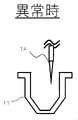
- FIG. 10 is an explanatory diagram of a normal state in which liquid exists in the dilution tank;
- FIG. 10 is an explanatory diagram of a case where there is no liquid in the dilution tank and there is an abnormality;
- FIG. 9 is a diagram showing a control block within the control device for executing the operations of the flow chart shown in FIG. 8;
- FIG. 10 is a partial explanatory view of a biochemical analyzer to which Example 2 is applied;
- Example 1 As an automatic analyzer, an example of an electrolyte analyzer will be described.
- Fig. 1 is an overall schematic diagram of an electrolyte analyzer, which is a flow-type electrolyte analyzer using ion-selective electrodes.
- the five main mechanisms of the electrolyte analyzer are the sample pipetting unit, ISE electrode unit, reagent unit, mechanism unit, and waste liquid mechanism, and control of these mechanisms as well as sample analysis such as calculation of electrolyte concentration based on measurement results.
- the sample pipetting unit has a sample probe 14.
- Sample probe 14 dispenses a sample such as a patient specimen held in sample container 15 and draws it into the analyzer.
- the ISE electrode section includes a dilution tank 11, a sipper nozzle 13, a diluent nozzle 24, an internal standard liquid nozzle 25, an ISE electrode (ion selective electrode) 1, a reference electrode 2, a pinch valve 23, a voltmeter 27, and an amplifier .
- the sample dispensed by the sample dispensing unit is discharged into the dilution tank 11 and diluted and stirred with the diluent discharged into the dilution tank 11 from the diluent nozzle 24 .
- the sipper nozzle 13 is connected to the ISE electrode 1 by a channel, and the diluted sample solution sucked from the dilution tank 11 is sent to the ISE electrode 1 .
- the reference electrode liquid stored in the reference electrode liquid bottle 5 is sent to the reference electrode 2 by operating the sipper syringe 10 with the pinch valve 23 closed.
- the ISE electrode 1 and the reference electrode 2 are electrically connected by the contact between the diluted sample solution sent to the ISE electrode channel and the reference electrode solution sent to the reference electrode channel.
- the ISE electrode unit measures the concentration of a specific electrolyte contained in the sample from the potential difference between the ISE electrode 1 and the reference electrode 2 .
- a control device (control unit) 29 which is an electrolyte analysis unit, calculates and displays the ion concentration in the specimen from the obtained electromotive force for each ion.
- the sample solution remaining in the dilution tank 11 is discharged by the waste liquid mechanism.
- the internal standard solution is discharged from the internal standard solution nozzle 25 into the dilution tank 11 and the measurement is performed.
- the reagent section includes a suction nozzle 6 for sucking a reagent adjusted to a predetermined ion concentration from a reagent container, a degassing mechanism 7, and a filter 16, and supplies reagents necessary for measurement.
- a suction nozzle 6 for sucking a reagent adjusted to a predetermined ion concentration from a reagent container
- a degassing mechanism 7, and a filter 16 supplies reagents necessary for measurement.
- three types of reagents are used as reagents: an internal standard solution, a diluent, and a reference electrode solution.
- a reference electrode solution bottle 5 containing a reference electrode solution is set in the reagent section.
- the internal standard solution bottle 3 and the diluent bottle 4 are connected to the internal standard solution nozzle 25 and the diluent solution nozzle 24 through the flow path through the filter 16, respectively.
- the reference electrode liquid bottle 5 is connected to the reference electrode 2 through a flow channel via a filter 16 .
- a degassing mechanism 7 is connected to the channel between the diluent bottle 4 and the dilution tank 11 and the channel between the reference electrode solution bottle 5 and the reference electrode 2, respectively.
- a degassed reagent is supplied into the reference electrode 2 .
- the mechanism unit includes an internal standard solution syringe 8, a diluent solution syringe 9, a sipper syringe 10, electromagnetic valves 17, 18, 19, 20, 21, 22, 30, and a preheater 12. etc.
- an internal standard solution and a diluent which are reagents, are sent to and discharged from the dilution tank 11 by the operation of an internal standard solution syringe 8 and a diluent solution syringe 9, respectively, and electromagnetic valves provided in the channels.
- the waste liquid mechanism includes a first waste liquid nozzle 26, a second waste liquid nozzle 36, a vacuum bottle 34, a waste liquid receiver 35, a vacuum pump 33, solenoid valves 31 and 32, and removes the sample solution remaining in the dilution tank 11 and the ISE electrode unit. The reaction solution remaining in the channel is discharged.
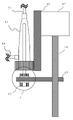
- FIG. 2 and 3 show a schematic configuration of a syringe pump unit in the internal standard syringe 8, diluent syringe 9 or sipper syringe 10 shown in FIG. It is a figure explaining operation
- the ball screw 48 is rotated by the motor 47 fixed to the base 46, and the drive plate 49 moves up and down.
- the plunger 45 moves up and down, causing liquid to flow into the inlet-side channel 44 connected to the housing 43 and to be discharged from the outlet-side channel 42 .
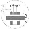
- FIG. 3 is an enlarged view of part A in FIG. As shown in FIG. 3, a backlash BL occurs between the drive plate 49 and the plunger 45 when the plunger fixing nut 50 is not installed.
- FIG. 4 is a diagram for explaining transition of backlash when the plunger fixing nut 50, which will be described later, is not installed in the syringe pump unit.
- FIG. 4A shows the liquid suction operation
- FIG. 4B shows the liquid ejection operation.
- the plunger 45 does not move vertically and remains stationary.
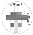
- FIG. 5 is a diagram for explaining the operation when the plunger fixing nut 50 is installed in the syringe pump unit.
- FIG. 6 is an enlarged view of the B section of FIG.
- the plunger 45 also moves up and down as the drive plate 49 moves up and down, and the state in which the plunger 45 remains stationary even when the drive plate 49 moves up and down is avoided.
- FIG. 7 is a diagram showing a syringe pump unit 60 as a reagent dispensing mechanism, which sucks the internal standard solution from the internal standard solution bottle 3 containing the internal standard solution as a reagent and supplies it to the internal standard solution nozzle (reagent nozzle) 25 .
- 4 is a diagram showing a syringe pump unit 60 that discharges from to the dilution tank 11.
- the motor 47, ball screw 48 and drive plate 49 form a plunger drive.
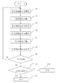
- FIG. 8 is an operation flowchart for detecting whether or not the plunger fixing nut 50 is installed in the syringe pump unit 60 in the first embodiment.
- the syringe pump unit 60 will be described as an example of the presence/absence detection processing of the plunger fixing nut 50.
- the internal standard solution contained in the internal standard solution bottle 3 passes through the suction side solenoid valve 30, the syringe pump unit 60, the discharge side solenoid valve 19 and the internal standard solution nozzle 25 into the dilution tank 11. Dispensed.
- the backlash BL distance between the plunger 45 and the driving plate 49 in Example 1 is 1.0 mm, and the driving resolution of the motor 47 is 20 [ ⁇ l/mm]. That is, in Example 1, the magnitude of the backlash BL corresponds to the driving amount of 20 ⁇ l. As a result, 20 ⁇ l suction/discharge operation is repeatedly performed. That is, the operation control unit 291, which will be described later, controls the operation so that the plunger 45 reciprocates by the distance of the backlash BL.
- step S1 The solenoid valve 30 on the suction side is opened (step S1), and the syringe pump unit 60 sucks 20 ⁇ l (step S2).
- step S3 the electromagnetic valve 30 on the suction side is closed (step S3), and the electromagnetic valve 19 on the discharge side is opened (step S4).
- step S5 the syringe pump unit 60 is operated to discharge 20 ⁇ l (step S5), and the electromagnetic valve 19 on the discharge side is closed (step S6).
- step S7 It is determined whether or not the suction and discharge operations of steps S1 to S6 have been performed 20 times, and if not performed 20 times, the process returns to step S1 (step S7).
- step S7 if the suction/discharge operation has been performed 20 times, proceed to step S8 to determine whether or not the amount of liquid in the dilution tank 11 is appropriate.
- step S8 if the amount of liquid in the dilution tank 11 is appropriate, proceed to step S9 and determine that the plunger fixing nut 50 is in a normal state.
- step S8 if the amount of liquid in the dilution tank 11 is not appropriate, proceed to step S10 and determine that the plunger fixing nut 50 is not installed and that the situation is abnormal.
- step S8 The determination of whether or not the liquid volume is appropriate in step S8 is detected using the liquid level detection function of the sample probe 14.
- the sample probe 14 is lowered from above the dilution tank 11 to a predetermined height after the suction/discharge operation. This height is the height reached when the liquid is discharged normally.
- the height is set to be equal to or lower than the height at which the liquid is normally ejected.
- This height must be set appropriately depending on the container shape of the dilution tank 11 and the number of repetitions of suction and discharge.
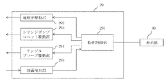
- FIG. 11 is a diagram showing control blocks within the control device 29 for executing the operations of the flowchart shown in FIG. Other functions such as the sample analysis function in the control device 29 are omitted from the illustration.
- the electromagnetic valve drive unit 292 supplies an operation command signal to the electromagnetic valves 19 and 30 to perform opening and closing operations.
- the syringe pump unit driving section 293 supplies an operation command signal to the motor 47 of the syringe pump unit 60 to operate the plunger 45 .
- the sample probe driving section 294 drives the sample probe 14 to perform the downward movement and upward movement to the dilution tank 11 .
- the liquid level detection unit 295 detects that the tip of the sample probe 14 has come into contact with the liquid level using the liquid level detection function.
- the operation control section 291 performs operation control so that the solenoid valve driving section 292, the syringe pump unit driving section 293, and the sample probe driving section 294 perform the operations of the flowchart shown in FIG.
- the operation control section 291 determines whether or not the liquid level reaches a predetermined height. display that it is normal. If the liquid level cannot be detected at a predetermined height even though the sample probe 14 descends the dilution tank 11, the operation control section 291 causes the display section 40 to output an alarm or the like as described above. The user is notified that the plunger fixing nut 50 is not attached by the method of (2), and is notified of the occurrence of backlash to prompt the user to attach the plunger fixing nut 50. - ⁇
- the first embodiment of the present invention it is possible to binarize and detect the normal state and the abnormal state by repeatedly performing the suction and discharge operation.
- the number of repetitions the number of reciprocating movements
- the amount of liquid stored in the dilution tank 11 can be changed in the normal state.
- the risk of erroneous determination can be reduced by storing in the dilution tank 11 a sufficient amount of liquid for determination of normality or abnormality.
- the shape of the storage tank (dilution tank 11 in Example 1) a shape with a high aspect ratio
- the liquid height per unit liquid volume it is possible to make a sufficient determination of normality and abnormality. It is possible to reduce the amount of liquid required. As a result, the number of repetitions can be reduced, and the execution time for this process can be shortened.
- the drive amount of the plunger 45 for suction and ejection can be set to any distance from the minimum distance smaller than the backlash BL to the maximum distance larger than the backlash BL.
- the distance from the minimum distance to the maximum distance can be arbitrarily set for each automatic analyzer. It is possible to realize a situation in which the liquid is ejected in the normal state and is not ejected in the abnormal state even when driven at the backlash BL or less.
- a driving amount equal to or greater than the amount of backlash BL is set and determined. In this case, for example, when the ejection operation is performed 20 times with a driving amount of 50 ⁇ l, 1000 ⁇ l of liquid is stored under normal conditions.
- the ejection amount is reduced by the amount of the backlash BL from the originally ejected amount in one suction ejection operation.
- the process of determining whether or not the plunger fixing nut 50 is present can be introduced, for example, during the initialization process after starting up the electrolyte analyzer (automatic analyzer).
- an electrolyte analyzer (automatic analyzer) capable of automatically detecting whether or not the plunger fixing nut 50 is attached to the syringe pump unit 60, and a failure detection method for the automatic analyzer.
- the syringe pump unit 60 sucks the internal standard solution contained in the internal standard solution bottle 3 and discharges it into the dilution tank (liquid container) 11. It is automatically detected whether or not the plunger fixing nut 50 is attached to the syringe pump unit of the diluent syringe 9 and the syringe pump unit of the sipper syringe 10 for sucking the contained diluent and discharging it into the dilution tank 11.
- the plunger fixing nut 50 is attached to the syringe pump unit of the diluent syringe 9 and the syringe pump unit of the sipper syringe 10 for sucking the contained diluent and discharging it into the dilution tank 11.
- the syringe pump unit 60 sucks the internal standard solution from the internal standard solution bottle 3 and dispenses (discharges) it from the internal standard solution nozzle (reagent nozzle) 25 into the dilution tank 11.
- the sample dispensing mechanism for aspirating the sample from the container 15 and dispensing (discharging) the sample (specimen) from the sample probe 14 to the reaction vessel 11 also includes the electromagnetic valve 19 on the discharge side and the electromagnetic valve 19 on the suction side shown in FIG. It has the same configuration as the valve 30 and the syringe pump unit 60 . Therefore, for the sample dispensing mechanism as well, the control device 29 determines whether or not the amount of discharged liquid is appropriate according to the flow chart shown in FIG. 8, and automatically detects whether or not the plunger fixing nut 50 is attached. It can be configured to
- Example 2 Next, Example 2 of the present invention will be described.
- a second embodiment is an example of application to a biochemical analyzer as an automatic analyzer.
- FIG. 12 is a partial explanatory diagram of the biochemical analyzer and a schematic configuration diagram of the sample dispensing mechanism.
- a sample pipetting probe 63 aspirates a sample from a sample container 64 and discharges it into a reaction container (liquid storage container) 65 .
- the suction and discharge operation of the sample by the sample pipetting probe 63 is performed by the operation of the suction-side electromagnetic valve 66, the syringe pump 61, and the discharge-side electromagnetic valve 62.
- FIG. Vertical movement and rotational movement of the sample pipetting probe 63 are performed by a mechanism such as a motor, but illustration thereof is omitted.
- the reagent aspirating/discharging section for aspirating the reagent from the reagent container in the biochemical analyzer and discharging it into the reaction container 65 has the same configuration as the sample aspirating/discharging section. Illustration and detailed description of the suction/discharge unit are omitted.
- the syringe pump unit 61 shown in FIG. 12 has the same configuration as the syringe pump unit 60 in Example 1, and the plunger fixing nut 50 is installed in a normal state.
- the biochemical analysis apparatus in Example 2 also includes a control device and a display unit similar to the control device 29 and display unit 40 in Example 1, and has a liquid level detection function.
- a control device (control unit) in a biochemical analyzer controls the operation of a sample dispensing mechanism and a reagent dispensing mechanism and analyzes a sample.
- Example 1 the liquid was discharged to the dilution tank 11, but in Example 2, the liquid was discharged to the reaction container 65, and whether or not the discharged liquid amount was appropriate was checked by the sample probe 63. It is determined using the face detection function.
- the process of determining whether or not the plunger fixing nut 50 is present can be introduced, for example, during the initialization process after starting up the biochemical analyzer (automatic analyzer).
- an automatic analyzer capable of automatically detecting a failure of the plunger 45 in the syringe pump unit 61 and a failure detection method for the automatic analyzer.
- a biochemical analyzer capable of automatically detecting whether or not the plunger fixing nut 50 is attached to the syringe pump unit 61 can be realized.
- the above example is the syringe pump unit 61 that aspirates the sample and discharges it from the sample probe 63 (sample nozzle) 63 into the reaction container 65.
- the reagent is aspirated from a reagent container similar to the sample container 64,
- a reagent dispensing mechanism for discharging a reagent from a reagent probe similar to the probe 63 to a reaction container 65 also has the same configuration as the discharge side electromagnetic valve 62, the suction side electromagnetic valve 66, and the syringe pump unit 61 shown in FIG. have. Therefore, by replacing the sample probe 63 in FIG. 12 with a reagent dispensing probe, it becomes equivalent to illustrating the reagent dispensing mechanism.
- the controller 29 determines whether or not the amount of discharged liquid is appropriate according to the flow chart shown in FIG. 8, and automatically detects whether or not the plunger fixing nut 50 is attached. configurable to
- the dilution tank 11 and the reaction vessel 65 can be collectively called a liquid container.
- a plunger failure is defined as a failure when the plunger fixing nut 50 is not installed and a failure when the plunger fixing nut 50 is not properly fixed.
- the present invention can realize an automatic analyzer and a failure detection method for an automatic analyzer that can automatically detect failure of a plunger in a syringe pump unit.
Landscapes
- Chemical & Material Sciences (AREA)
- Health & Medical Sciences (AREA)
- Analytical Chemistry (AREA)
- Clinical Laboratory Science (AREA)
- Chemical Kinetics & Catalysis (AREA)
- Physics & Mathematics (AREA)
- Life Sciences & Earth Sciences (AREA)
- Biochemistry (AREA)
- General Health & Medical Sciences (AREA)
- General Physics & Mathematics (AREA)
- Immunology (AREA)
- Pathology (AREA)
- Medicinal Chemistry (AREA)
- Automatic Analysis And Handling Materials Therefor (AREA)
Priority Applications (4)
| Application Number | Priority Date | Filing Date | Title |
|---|---|---|---|
| US18/548,552 US20240159789A1 (en) | 2021-03-26 | 2021-12-03 | Automated analysis device |
| JP2023508459A JP7547613B2 (ja) | 2021-03-26 | 2021-12-03 | 自動分析装置 |
| CN202180094737.2A CN116940846A (zh) | 2021-03-26 | 2021-12-03 | 自动分析装置 |
| EP21933243.4A EP4317982A4 (en) | 2021-03-26 | 2021-12-03 | Automated analysis device |
Applications Claiming Priority (2)
| Application Number | Priority Date | Filing Date | Title |
|---|---|---|---|
| JP2021052718 | 2021-03-26 | ||
| JP2021-052718 | 2021-03-26 |
Publications (1)
| Publication Number | Publication Date |
|---|---|
| WO2022201645A1 true WO2022201645A1 (ja) | 2022-09-29 |
Family
ID=83395265
Family Applications (1)
| Application Number | Title | Priority Date | Filing Date |
|---|---|---|---|
| PCT/JP2021/044510 Ceased WO2022201645A1 (ja) | 2021-03-26 | 2021-12-03 | 自動分析装置 |
Country Status (5)
| Country | Link |
|---|---|
| US (1) | US20240159789A1 (https=) |
| EP (1) | EP4317982A4 (https=) |
| JP (1) | JP7547613B2 (https=) |
| CN (1) | CN116940846A (https=) |
| WO (1) | WO2022201645A1 (https=) |
Families Citing this family (2)
| Publication number | Priority date | Publication date | Assignee | Title |
|---|---|---|---|---|
| WO2022074730A1 (ja) * | 2020-10-06 | 2022-04-14 | 株式会社日立ハイテク | 試料処理デバイス、試料処理装置及び試料の処理方法 |
| EP4671772A2 (en) * | 2024-03-14 | 2025-12-31 | Leica Microsystems CMS GmbH | FLUID DISTRIBUTOR FOR SUPPLYING FLUID TO A MICROFLUID SYSTEM AND FLUID CONTAINER |
Citations (4)
| Publication number | Priority date | Publication date | Assignee | Title |
|---|---|---|---|---|
| JP2002350453A (ja) * | 2001-05-30 | 2002-12-04 | Aloka Co Ltd | 分注装置 |
| JP2006038661A (ja) * | 2004-07-28 | 2006-02-09 | Yaskawa Electric Corp | 分注ヘッド |
| US20200030794A1 (en) * | 2018-04-02 | 2020-01-30 | Dropworks, Inc. | Systems and methods for serial flow emulsion processes |
| JP2020143927A (ja) * | 2019-03-04 | 2020-09-10 | 株式会社日立ハイテク | 自動分析装置 |
Family Cites Families (3)
| Publication number | Priority date | Publication date | Assignee | Title |
|---|---|---|---|---|
| JP2006098226A (ja) * | 2004-09-29 | 2006-04-13 | Fuji Photo Film Co Ltd | シリンジポンプの異常検出方法及び液体吸引吐出器並びに生化学分析装置 |
| JP5372975B2 (ja) * | 2011-01-31 | 2013-12-18 | 株式会社日立ハイテクノロジーズ | 分注装置および当該分注装置を備えた分析装置 |
| JP6828077B2 (ja) * | 2019-03-28 | 2021-02-10 | シスメックス株式会社 | 吸引管の洗浄方法および試料測定装置 |
-
2021
- 2021-12-03 US US18/548,552 patent/US20240159789A1/en active Pending
- 2021-12-03 CN CN202180094737.2A patent/CN116940846A/zh active Pending
- 2021-12-03 EP EP21933243.4A patent/EP4317982A4/en active Pending
- 2021-12-03 WO PCT/JP2021/044510 patent/WO2022201645A1/ja not_active Ceased
- 2021-12-03 JP JP2023508459A patent/JP7547613B2/ja active Active
Patent Citations (4)
| Publication number | Priority date | Publication date | Assignee | Title |
|---|---|---|---|---|
| JP2002350453A (ja) * | 2001-05-30 | 2002-12-04 | Aloka Co Ltd | 分注装置 |
| JP2006038661A (ja) * | 2004-07-28 | 2006-02-09 | Yaskawa Electric Corp | 分注ヘッド |
| US20200030794A1 (en) * | 2018-04-02 | 2020-01-30 | Dropworks, Inc. | Systems and methods for serial flow emulsion processes |
| JP2020143927A (ja) * | 2019-03-04 | 2020-09-10 | 株式会社日立ハイテク | 自動分析装置 |
Also Published As
| Publication number | Publication date |
|---|---|
| CN116940846A (zh) | 2023-10-24 |
| EP4317982A1 (en) | 2024-02-07 |
| US20240159789A1 (en) | 2024-05-16 |
| JP7547613B2 (ja) | 2024-09-09 |
| EP4317982A4 (en) | 2024-12-25 |
| JPWO2022201645A1 (https=) | 2022-09-29 |
Similar Documents
| Publication | Publication Date | Title |
|---|---|---|
| JP7216815B2 (ja) | 自動分析装置、及びその洗浄方法 | |
| US12326459B2 (en) | Automatic analyzer | |
| US9335335B2 (en) | Automatic analyzer | |
| US9110042B2 (en) | Clinical specimen processing apparatus and clinical specimen processing system | |
| CN106461693B (zh) | 自动分析装置 | |
| US8475740B2 (en) | Liquid dispensing apparatus | |
| JP5122949B2 (ja) | 分注量検出方法および吸液モニタ型分注装置 | |
| CN112654862A (zh) | 电解质浓度测量装置 | |
| US9897624B2 (en) | Automatic analyzer | |
| US20140220693A1 (en) | Automatic analyzer | |
| CN103201634B (zh) | 自动分析装置 | |
| JP2018096915A (ja) | 自動分析装置 | |
| WO2022201645A1 (ja) | 自動分析装置 | |
| JP7195452B2 (ja) | 自動分析装置 | |
| WO2025197528A1 (ja) | 自動分析装置 | |
| CN118401842A (zh) | 自动分析装置、分注方法 | |
| JP7167037B2 (ja) | 自動分析装置および検体分注機構の異常検出方法 | |
| JP3120180U (ja) | 自動分析装置 | |
| US20260104432A1 (en) | Dispensing device and probe state checking method | |
| JP7716485B2 (ja) | 分注装置及び分注方法 | |
| JP7606626B2 (ja) | 分注装置及び分注方法 | |
| JP2012137436A (ja) | 自動分析装置 | |
| JP2024008589A (ja) | 自動分析装置 | |
| WO2022259767A1 (ja) | 分注装置、自動分析装置及び分注方法 |
Legal Events
| Date | Code | Title | Description |
|---|---|---|---|
| 121 | Ep: the epo has been informed by wipo that ep was designated in this application |
Ref document number: 21933243 Country of ref document: EP Kind code of ref document: A1 |
|
| ENP | Entry into the national phase |
Ref document number: 2023508459 Country of ref document: JP Kind code of ref document: A |
|
| WWE | Wipo information: entry into national phase |
Ref document number: 202180094737.2 Country of ref document: CN |
|
| WWE | Wipo information: entry into national phase |
Ref document number: 18548552 Country of ref document: US |
|
| WWE | Wipo information: entry into national phase |
Ref document number: 2021933243 Country of ref document: EP |
|
| NENP | Non-entry into the national phase |
Ref country code: DE |
|
| ENP | Entry into the national phase |
Ref document number: 2021933243 Country of ref document: EP Effective date: 20231026 |