WO2022201612A1 - 基板処理方法、および、基板処理装置 - Google Patents
基板処理方法、および、基板処理装置 Download PDFInfo
- Publication number
- WO2022201612A1 WO2022201612A1 PCT/JP2021/039269 JP2021039269W WO2022201612A1 WO 2022201612 A1 WO2022201612 A1 WO 2022201612A1 JP 2021039269 W JP2021039269 W JP 2021039269W WO 2022201612 A1 WO2022201612 A1 WO 2022201612A1
- Authority
- WO
- WIPO (PCT)
- Prior art keywords
- substrate
- main surface
- etching
- cooling
- substrate processing
- Prior art date
- Legal status (The legal status is an assumption and is not a legal conclusion. Google has not performed a legal analysis and makes no representation as to the accuracy of the status listed.)
- Ceased
Links
Images










Classifications
-
- H—ELECTRICITY
- H10—SEMICONDUCTOR DEVICES; ELECTRIC SOLID-STATE DEVICES NOT OTHERWISE PROVIDED FOR
- H10P—GENERIC PROCESSES OR APPARATUS FOR THE MANUFACTURE OR TREATMENT OF DEVICES COVERED BY CLASS H10
- H10P50/00—Etching of wafers, substrates or parts of devices
-
- H—ELECTRICITY
- H10—SEMICONDUCTOR DEVICES; ELECTRIC SOLID-STATE DEVICES NOT OTHERWISE PROVIDED FOR
- H10P—GENERIC PROCESSES OR APPARATUS FOR THE MANUFACTURE OR TREATMENT OF DEVICES COVERED BY CLASS H10
- H10P50/00—Etching of wafers, substrates or parts of devices
- H10P50/20—Dry etching; Plasma etching; Reactive-ion etching
- H10P50/24—Dry etching; Plasma etching; Reactive-ion etching of semiconductor materials
- H10P50/242—Dry etching; Plasma etching; Reactive-ion etching of semiconductor materials of Group IV materials
-
- H—ELECTRICITY
- H10—SEMICONDUCTOR DEVICES; ELECTRIC SOLID-STATE DEVICES NOT OTHERWISE PROVIDED FOR
- H10P—GENERIC PROCESSES OR APPARATUS FOR THE MANUFACTURE OR TREATMENT OF DEVICES COVERED BY CLASS H10
- H10P50/00—Etching of wafers, substrates or parts of devices
- H10P50/69—Etching of wafers, substrates or parts of devices using masks for semiconductor materials
- H10P50/691—Etching of wafers, substrates or parts of devices using masks for semiconductor materials for Group V materials or Group III-V materials
-
- H—ELECTRICITY
- H10—SEMICONDUCTOR DEVICES; ELECTRIC SOLID-STATE DEVICES NOT OTHERWISE PROVIDED FOR
- H10P—GENERIC PROCESSES OR APPARATUS FOR THE MANUFACTURE OR TREATMENT OF DEVICES COVERED BY CLASS H10
- H10P52/00—Grinding, lapping or polishing of wafers, substrates or parts of devices
Definitions
- the present invention relates to a substrate processing method for processing a substrate and a substrate processing apparatus for processing a substrate.
- Substrates to be processed include, for example, semiconductor wafers, FPD (Flat Panel Display) substrates such as liquid crystal display devices and organic EL (Electroluminescence) display devices, optical disk substrates, magnetic disk substrates, and magneto-optical disk substrates. , photomask substrates, ceramic substrates, solar cell substrates, and the like.
- FPD Full Panel Display
- organic EL Electrode
- Photomask substrates ceramic substrates, solar cell substrates, and the like.
- the formation of memory holes with a high aspect ratio is required.
- the layer to be processed is not sufficiently etched on the bottom side of the memory hole, and the shape of the memory hole tapers from the opening toward the bottom. It may become tapered.
- Patent Document 1 proposes a technique of forming a memory hole having a straight side wall by using a mask layer having a grating structure in which amorphous silicon layers and spaces are alternately arranged (stacked). .
- one object of the present invention is to provide a substrate processing method and a substrate processing apparatus capable of improving the uniformity of the width of a recess provided in the main surface of a substrate in the depth direction of the recess. .
- An embodiment of the present invention provides a substrate processing method for processing a substrate having a first principal surface and a second principal surface opposite to the first principal surface.
- the substrate processing method includes an etching solution supplying step of supplying an etching solution containing an etching component and a gelling agent to the first main surface, and after the etching solution supplying step, the etching solution is heated to a freezing point of the gelling agent or less. and a rinsing step of supplying a rinse liquid having a temperature equal to or higher than the melting point of the gelling agent to the first main surface while continuing to cool the second main surface. and a cooling stop step of stopping cooling of the second main surface after the rinse liquid supply step.
- the etching liquid is supplied to the first main surface of the substrate. If a substrate having recesses formed on the first main surface is used, the etching solution supplied to the first main surface enters the recesses. After the etching treatment liquid is supplied to the first main surface of the substrate, the second main surface is cooled to a temperature below the freezing point of the gelling agent. Therefore, the temperature of the substrate reaches a temperature below the freezing point of the gelling agent, and the etching solution on the first main surface turns into gel. Therefore, gel is also formed in the recess.
- a rinse liquid having a temperature equal to or higher than the melting point of the gelling agent is supplied to the first main surface. Therefore, the opening-side portion of the gel located at the opening of the recess changes into the etching solution, and the etching solution formed by the solification of the opening-side portion is replaced by the rinse liquid and removed from the recess.
- the bottom-side portion closer to the bottom than the opening-side portion is closer to the second main surface than the opening-side portion, so it is susceptible to the cooling of the second main surface. Therefore, by continuing to cool the second main surface while the rinse liquid is being supplied to the first main surface, it is possible to supply the upper surface of the substrate W with the rinse liquid having a temperature equal to or higher than the melting point of the gelling agent. Regardless, the bottom portion can remain in the gel state.
- the cooling of the second main surface is stopped.
- the temperature of the gel remaining in the recesses rises, and the gel remaining in the recesses changes into an etching treatment liquid.
- the etching component diffuses into the rinse liquid in contact with the etching solution.
- a concentration gradient of the etching component is generated within the recess such that the concentration of the etching component decreases from the bottom of the recess toward the opening. Therefore, an etching rate gradient is generated from the opening of the recess toward the bottom.
- the width of the recess on the bottom side is widened so that the recess approaches a straight shape. As a result, it is possible to improve the uniformity of the width of the recesses in the depth direction of the recesses provided on the first main surface of the substrate.
- the cooling stop step includes a heating step of heating the second main surface to a temperature equal to or higher than the melting point.
- the temperature of the gel remaining in the recesses can be quickly increased to change the gel remaining in the recesses into the etching treatment liquid. Therefore, etching of the substrate can be started quickly.
- the heating step includes heating the substrate from the second main surface side by supplying a heating fluid having a temperature equal to or higher than the melting point to the second main surface. include.
- the substrate can be heated from the second main surface side, that is, the second main surface can be heated by a simple method of supplying a heating fluid.
- the heating step includes heating the substrate from the second main surface side by a hot plate facing the second main surface from below and having a temperature equal to or higher than the melting point.
- the entire second main surface can be heated with high uniformity.
- the cooling step includes cooling the substrate from the second main surface side by supplying a cooling fluid having a temperature equal to or lower than the freezing point to the second main surface.
- the substrate can be cooled from the second main surface side, that is, the second main surface can be cooled by a simple method of supplying a cooling fluid.
- the cooling step includes cooling the substrate from the second main surface side by a cooling plate facing the second main surface from below and having a temperature equal to or lower than the freezing point.
- the entire second main surface can be cooled with high uniformity.
- the recess has a depth of 0.5 ⁇ m or more and 1.5 ⁇ m or less, and an aspect ratio of the recess is 20 or more and 100 or less.
- a recess having such dimensions may have a tapered shape that tapers from the opening toward the bottom. Therefore, if the above-described substrate processing is performed using a substrate having a first main surface in which recesses having such dimensions are formed, the depth of the recesses provided on the first main surface of the substrate will be reduced. width uniformity can be improved.
- the substrate processing method further includes a supply restart step of restarting supply of the rinse liquid after the cooling stop step.
- the supply of the rinse liquid to the first main surface of the substrate is resumed after the cooling stop process. Specifically, after the cooling of the substrate is stopped, the temperature of the gel remaining in the recesses rises, and the gel remaining in the recesses changes into the etching treatment liquid, the supply of the rinsing liquid to the first main surface of the substrate is resumed. be done. Therefore, etching by the etching component proceeds while the etching component in the etching solution is diffused in the recess, and after the width of the recess on the bottom side is appropriately widened, the etching solution in the recess is removed from the recess by the rinse liquid. can be removed. As a result, it is possible to improve the uniformity of the width of the recesses in the depth direction of the recesses provided on the first main surface of the substrate.
- the substrate processing method further includes an auxiliary heating step of heating the substrate from the second main surface side while the rinse liquid is being supplied to the substrate in the supply restarting step.
- the substrate is heated from the second main surface side when the rinsing liquid is supplied to the first main surface to remove the etching treatment liquid in the concave portions. Therefore, it is possible to prevent the temperature of the etching solution in the concave portion from decreasing during the supply of the rinse solution. Therefore, it is possible to prevent the etchant from turning into gel in the recesses and leaving etching components in the recesses.
- the substrate processing method further includes a dry etching step of dry-etching the first main surface of the substrate before the etchant solution supply step. Therefore, even when using a substrate in which no recess is formed on the first main surface, the recess can be formed on the first main surface.
- the substrate processing apparatus includes an etching solution supply member that supplies an etching solution containing an etching component and a gelling agent to the first main surface; and a rinse liquid supply member that supplies a rinse liquid having a temperature equal to or higher than the melting point of the gelling agent to the first main surface.
- the etching liquid is supplied to the first main surface of the substrate from the etching liquid supply member. If a substrate having recesses formed on the first main surface is used, the etching solution supplied to the first main surface enters the recesses.
- the second main surface of the substrate with the etching treatment liquid attached to the first main surface is cooled to a temperature below the freezing point of the gelling agent, the temperature of the substrate reaches a temperature below the freezing point of the gelling agent. Then, the etching solution on the first main surface changes to gel. Therefore, gel is also formed in the recess.
- the opening side portion of the gel located at the opening of the concave portion is removed. It changes to an etching solution. Therefore, the etching solution formed by the solification of the opening side portion can be removed from the concave portion by the rinsing solution.
- the bottom-side portion closer to the bottom than the opening-side portion is closer to the second main surface than the opening-side portion, so it is susceptible to the cooling of the second main surface. Therefore, by continuing to cool the second main surface while the rinse liquid is being supplied to the first main surface, it is possible to supply the upper surface of the substrate W with the rinse liquid having a temperature equal to or higher than the melting point of the gelling agent. Regardless, the bottom portion can remain in the gel state.
- the temperature of the gel remaining in the concave portions rises, and the gel remaining in the concave portions changes into the etching treatment liquid. .
- the etching component diffuses into the rinse liquid in contact with the etching solution.
- a concentration gradient of the etching component is generated in the recess such that the concentration of the etching component decreases from the bottom of the recess toward the opening. Therefore, an etching rate gradient is generated from the opening of the recess toward the bottom.
- the width of the recess on the bottom side is widened so that the recess approaches a straight shape. As a result, it is possible to improve the uniformity of the width of the recesses in the depth direction of the recesses provided on the first main surface of the substrate.
- the substrate processing apparatus further includes a heating member that heats the second main surface to a temperature equal to or higher than the melting point. Therefore, if the second main surface is heated to a temperature equal to or higher than the melting point of the gelling agent after the supply of the rinsing liquid to the first main surface is stopped, the temperature of the gel remaining in the recesses is quickly increased and remains in the recesses. The gel can be changed into an etching treatment liquid. Therefore, etching of the substrate can be started quickly.
- the recess has a depth of 0.5 ⁇ m or more and 1.5 ⁇ m or less, and an aspect ratio of the recess is 20 or more and 100 or less.
- a recess having such dimensions may have a tapered shape that tapers from the opening side toward the bottom side. Therefore, if the above-described substrate processing is performed using a substrate having a first main surface in which recesses having such dimensions are formed, the depth of the recesses provided on the first main surface of the substrate will be reduced. width uniformity can be improved.
- the substrate processing apparatus further includes a dry processing unit that performs dry etching processing on the first main surface of the substrate. Therefore, even when using a substrate in which no recess is formed on the first main surface, the recess can be formed on the first main surface.
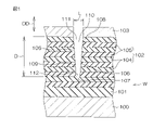
- FIG. 1 is a schematic cross-sectional view for explaining the structure of a substrate to be processed.
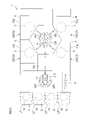
- FIG. 2A is a plan view for explaining the configuration of the substrate processing apparatus according to the first embodiment of the invention.
- FIG. 2B is an elevation view for explaining the configuration of the substrate processing apparatus.
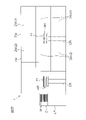
- FIG. 3 is a cross-sectional view for explaining a configuration example of a wet processing unit provided in the substrate processing apparatus.
- FIG. 4 is a block diagram for explaining a configuration example related to control of the substrate processing apparatus.
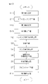
- FIG. 5 is a flowchart for explaining an example of substrate processing performed by the substrate processing apparatus.
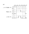
- FIG. 6 is a time chart regarding the fluid supplied to the substrate in the substrate processing.
- FIG. 7A is a schematic diagram for explaining the state of the substrate during the substrate processing.
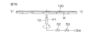
- FIG. 7B is a schematic diagram for explaining the state of the substrate during the substrate processing.
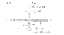
- FIG. 7C is a schematic diagram for explaining the state of the substrate during the substrate processing.
- FIG. 7D is a schematic diagram for explaining the state of the substrate during the substrate processing.
- FIG. 7E is a schematic diagram for explaining the state of the substrate during the substrate processing.
- FIG. 8 is a schematic diagram for explaining the state of the vicinity of the upper surface of the substrate during the substrate processing.
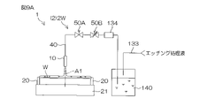
- FIG. 9A is a schematic diagram for explaining a first example of a method of supplying an etching treatment liquid to a substrate.
- FIG. 9B is a schematic diagram for explaining a second example of the method of supplying the etching solution to the substrate.
- FIG. 9A is a schematic diagram for explaining a first example of a method of supplying an etching treatment liquid to a substrate.
- FIG. 9B is a schematic diagram for explaining a second example of the method of supplying the etching solution to the substrate.
- FIG. 9C is a schematic diagram for explaining a third example of the method of supplying the etching solution to the substrate.
- FIG. 10 is a time chart for explaining the first modification of the substrate processing.
- FIG. 11 is a time chart for explaining the second modification of the substrate processing.
- FIG. 12 is a plan view for explaining the configuration of the substrate processing apparatus according to the second embodiment of the invention.
- FIG. 13 is a flowchart for explaining an example of substrate processing performed by the substrate processing apparatus.
- FIG. 14A is a schematic cross-sectional view for explaining the state of the vicinity of the upper surface of the substrate before dry etching is performed in the substrate processing according to the second embodiment.
- FIG. 14B is a schematic cross-sectional view for explaining the state of the vicinity of the upper surface of the substrate after the dry etching process has been performed.
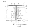
- FIG. 15A is a schematic diagram for explaining a modification of the cooling member.
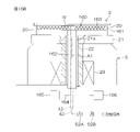
- FIG. 15B is a schematic diagram for explaining a modification of the heating member.
- FIG. 1 is a schematic cross-sectional view for explaining the structure of a substrate W to be processed.
- the substrate W has a pair of main surfaces.
- the substrate W includes a semiconductor layer 100 having a pair of main surfaces, an insulating layer 101 formed on at least one main surface of the semiconductor layer 100, a laminate 102 formed on the insulating layer 101, and a laminate 102 and a mask layer 103 formed thereon.
- the laminate 102 has multiple layers of insulating layers 104 and multiple layers of sacrificial layers 105 . In the laminate 102, the insulating layers 104 and the sacrificial layers 105 are alternately arranged.
- the semiconductor layer 100 is made of Si single crystal, for example.
- Insulating layer 101 is, for example, a silicon oxide film (SiO 2 film).
- Insulating layer 104 and sacrificial layer 105 forming laminate 102 are made of different materials.
- insulating layer 104 is a silicon oxide film and sacrificial layer 105 is a silicon nitride film (SiN).
- the sacrificial layer 105 is replaced with an electrode layer (not shown) such as a silicon layer in a step after substrate processing (see FIG. 5), which will be described later.
- Mask layer 103 is made of, for example, amorphous carbon.
- a recess 110 is formed in a region of the surface of the laminate 102 where the mask layer 103 is not formed.
- the recess 110 is formed in at least one of the pair of main surfaces of the substrate W. As shown in FIG.
- the main surface on which the recess 110 is formed is called the first main surface, and the main surface opposite to the first main surface is called the second main surface.
- the recesses 110 are formed on both of a pair of main surfaces of the substrate W, one of the main surfaces is the first main surface, and the main surface opposite to the first main surface is the second main surface. is.
- the recess 110 has an opening 111 and a bottom 112 , and the depth direction DD of the recess 110 matches the stacking direction of the laminate 102 .
- the depth D of the recess 110 is, for example, 0.5 ⁇ m or more and 1.5 ⁇ m or less.
- the aspect ratio of recess 110 is, for example, 20 or more and 100 or less.
- Recess 110 has a tapered shape that tapers from opening 111 toward bottom 112 .
- a width L of the recess 110 decreases from the opening 111 toward the bottom 112 .
- the recess 110 may have a tapered shape that tapers from the opening 111 toward the bottom 112 even if this dimensional relationship is not met.
- the laminate 102 has a pair of side walls 106 inclined with respect to the depth direction DD so as to approach each other from the opening 111 toward the bottom 112, and a bottom wall 107 connecting the pair of side walls 106.
- Each sidewall 106 includes an opening sidewall 108 that defines the opening 111 of the recess 110 and a bottom sidewall 109 that defines the bottom 112 side of the opening 111 of the recess 110 .
- FIG. 2A is a plan view for explaining the configuration of the substrate processing apparatus 1 according to the first embodiment of the invention.
- FIG. 2B is an elevation view for explaining the configuration of the substrate processing apparatus 1.
- the substrate processing apparatus 1 is a single-wafer type apparatus that processes substrates W one by one.
- the substrate W has a disk shape.
- the substrate W is processed with the first main surface in which the recess 110 (see FIG. 1) is formed facing upward.
- the substrate processing apparatus 1 includes a plurality of processing units 2 for processing substrates W, a load port LP on which a carrier C containing a plurality of substrates W to be processed by the processing units 2 is mounted, the load port LP and processing. It includes transport robots IR and CR that transport substrates W between units 2 and controller 3 that controls substrate processing apparatus 1 .
- the transport robot IR transports the substrate W between the carrier C and the transport robot CR.
- the transport robot CR transports the substrate W between the transport robot IR and the processing unit 2 .
- Each of the transfer robots IR and CR has, for example, a pair of articulated arms AR and a pair of hands H (see FIG. 2B ) and a multi-joint arm robot.
- the plurality of processing units 2 form four processing towers TW arranged at four horizontally separated positions.
- Each processing tower TW includes a plurality of (for example, three) processing units 2 stacked vertically.
- the four processing towers TW are arranged two by two on each side of the transport route TR extending from the load port LP toward the transport robots IR and CR.
- the processing unit 2 is a wet processing unit 2W that processes the substrate W with liquid.
- Each wet processing unit 2W includes a chamber 4 and a processing cup 7 disposed within the chamber 4, and processes the substrate W within the processing cup 7. As shown in FIG.
- the chamber 4 is formed with an entrance (not shown) for loading and unloading the substrate W by the transport robot CR.
- the chamber 4 is provided with a shutter unit (not shown) that opens and closes this entrance.
- FIG. 3 is a schematic cross-sectional view for explaining a configuration example of the wet processing unit 2W.
- the wet processing unit 2W further includes a spin chuck 5 that rotates the substrate W around the rotation axis A1 (vertical axis) while holding the substrate W at a predetermined holding position.
- the rotation axis A1 passes through the center of the substrate W and is orthogonal to each major surface of the substrate W. As shown in FIG. That is, the rotation axis A1 extends vertically.
- the holding position is the position of the substrate W shown in FIG. 3, and is the position where the substrate W is held in a horizontal posture.
- the spin chuck 5 includes a spin base 21 having a disk shape along the horizontal direction, a plurality of chuck pins 20 for gripping the substrate W above the spin base 21 and holding the substrate W at a holding position, and an upper end portion of the spin base 21 . are connected to each other and extend in the vertical direction, and a rotary drive mechanism 23 that rotates the rotary shaft 22 around its central axis (rotational axis A1).
- the spin chuck 5 is an example of a substrate holding member that rotates the substrate W around the rotation axis A1 while holding the substrate W at the holding position.
- a plurality of chuck pins 20 are arranged on the upper surface of the spin base 21 at intervals in the circumferential direction of the spin base 21 .
- the rotation drive mechanism 23 is, for example, an actuator such as an electric motor.
- the rotation drive mechanism 23 rotates the rotation shaft 22 to rotate the spin base 21 and the plurality of chuck pins 20 around the rotation axis A1. Thereby, the substrate W is rotated around the rotation axis A1 together with the spin base 21 and the plurality of chuck pins 20 .
- the plurality of chuck pins 20 are movable between a closed position in which they are in contact with the peripheral edge of the substrate W to grip the substrate W and an open position in which they are retracted from the peripheral edge of the substrate W.
- the multiple chuck pins 20 are moved by an opening/closing mechanism (not shown).
- the opening/closing mechanism includes, for example, a link mechanism and an actuator that applies a driving force to the link mechanism.
- the processing cup 7 receives liquid splashed from the substrate W held by the spin chuck 5 .
- the processing cup 7 has a plurality of guards 30 (two in the example of FIG. 3) for receiving the liquid splashing outward from the substrate W held by the spin chuck 5, and the liquid guided downward by the plurality of guards 30. It includes a plurality (two in the example of FIG. 3) of cups 31 for receiving each, and a cylindrical outer wall member 32 surrounding the plurality of guards 30 and the plurality of cups 31 .
- the plurality of guards 30 are individually raised and lowered by a guard elevation drive mechanism (not shown).
- the guard elevating drive mechanism includes, for example, an actuator such as an electric motor or an air cylinder that drives each guard 30 up and down.
- the wet processing unit 2W includes an etching processing liquid nozzle 10 for supplying an etching processing liquid to the upper surface (upper main surface) of the substrate W held by the spin chuck 5, and a rinsing unit for rinsing the upper surface of the substrate W held by the spin chuck 5.
- a rinse liquid nozzle 11 for supplying the liquid is further provided.
- the etching treatment liquid contains an etching component and a gelling agent as solutes, and a solvent that dissolves the solutes.
- the solvent contained in the etching solution is, for example, water such as DIW (deionized water). However, the solvent is not limited to DIW.
- the etching component has the property of etching the stack 102 of substrates W (see FIG. 1). Specifically, the etching component etches the portion (the pair of sidewalls 106 ) that defines the recess 110 in the laminate 102 .
- the etching component is, for example, hydrofluoric acid or APM (ammonia-hydrogen peroxide mixture).
- the etching components are strictly etching ions, HF 2 ⁇ or NH 4 + .
- the gelling agent is, for example, gelatin, agar, or a mixture thereof.
- the melting point and freezing point of the gelling agent are usually different from each other, the melting point of the gelling agent being higher than the freezing point of the gelling agent.
- the melting point of the gelling agent is, for example, 20° C. or higher and 30° C. or lower, and the freezing point of the gelling agent is, for example, 15° C. or higher and 25° C. or lower.
- the melting point and freezing point of the gelling agent vary depending on the blending ratio (concentration) of the gelling agent in the etching solution, the type of gelling agent, and the like.
- the freezing point of the gelling agent is preferably lower than the room temperature (for example, 25° C.) in the clean room in which the substrate processing apparatus 1 is arranged.
- the melting point and freezing point of the gelling agent are not limited to the above ranges.
- the melting point of the gelling agent is 85°C or higher and 93°C or lower
- the freezing point of the gelling agent is 33°C or higher and 45°C or lower.
- the etching solution changes to an etching gel by cooling below the freezing point of the gelling agent.
- Gelation refers to the change of the etching solution into an etching gel.
- the etching gel changes into an etching treatment liquid by being heated above the melting point of the gelling agent.
- the conversion of the etching gel into an etching treatment liquid is called solification. Therefore, the etching treatment liquid is also called an etching sol.
- the etching gel has a lower etching performance for etching the substrate W than the etching liquid. Therefore, the etching of the substrate W can be stopped by changing the etching solution adhering to the upper surface of the substrate W into the etching gel, and the etching of the substrate W can be started by changing the etching gel into the etching solution. can do.
- the rinse liquid is, for example, water such as DIW.
- the rinse liquid is not limited to DIW, but includes DIW, carbonated water, electrolyzed ion water, hydrochloric acid water with a dilution concentration (for example, 1 ppm or more and 100 ppm or less), and a dilution concentration (for example, 1 ppm or more and 100 ppm or less). contains at least one of ammonia water and reduced water (hydrogen water).
- Both the etching treatment liquid nozzle 10 and the rinse liquid nozzle 11 are mobile nozzles that can move at least in the horizontal direction.
- the etching treatment liquid nozzle 10 and the rinse liquid nozzle 11 are horizontally moved by a plurality of nozzle moving mechanisms (first nozzle moving mechanism 35 and second nozzle moving mechanism 36).
- Each nozzle moving mechanism includes an arm (not shown) that supports the corresponding nozzle and an arm moving mechanism (not shown) that horizontally moves the corresponding arm.
- Each arm movement mechanism includes actuators such as electric motors and air cylinders.
- the etching solution nozzle 10 and the rinse solution nozzle 11 may be configured to be integrally moved by a common nozzle moving mechanism.
- the etching treatment liquid nozzle 10 and the rinse liquid nozzle 11 may be configured to be movable also in the vertical direction.
- the etchant solution nozzle 10 is connected to an etchant solution pipe 40 that guides the etchant solution to the etchant solution nozzle 10 .
- the etching solution pipe 40 is provided with an etching solution valve 50A that opens and closes a channel in the etching solution pipe 40, and an etching solution flow control valve 50B that adjusts the flow rate of the etching solution in the channel. is dressed.
- the etchant solution valve 50A When the etchant solution valve 50A is opened, the etchant solution is continuously discharged downward from the outlet of the etchant solution nozzle 10 at a flow rate corresponding to the degree of opening of the etchant solution flow control valve 50B.
- the etching solution nozzle 10 is an example of an etching solution supply member. The temperature of the etching solution discharged from the etching solution nozzle 10 is higher than the freezing point of the gelling agent.
- the rinse liquid nozzle 11 is connected to a rinse liquid pipe 41 that guides the rinse liquid to the rinse liquid nozzle 11 .
- the rinse liquid pipe 41 is provided with a rinse liquid valve 51A that opens and closes a flow path in the rinse liquid pipe 41, and a rinse liquid flow rate control valve 51B that adjusts the flow rate of the rinse liquid in the flow path.
- the rinse liquid nozzle 11 is an example of a rinse liquid supply member.
- the wet processing unit 2W further includes a lower fluid nozzle 12 that supplies fluid to the lower surface (lower main surface) of the substrate W held by the spin chuck 5.
- the lower fluid nozzle 12 is inserted into the inner space of the rotating shaft 22 and the through hole 21 a that opens at the center of the upper surface of the spin base 21 .
- a discharge port 12 a of the lower fluid nozzle 12 is exposed from the upper surface of the spin base 21 .
- the discharge port 12a of the lower fluid nozzle 12 faces the central region of the lower surface of the substrate W from below.
- the central region of the bottom surface of the substrate W is the region including the center of rotation of the substrate W on the bottom surface of the substrate W. As shown in FIG.
- the lower fluid nozzle 12 selectively applies a fluid such as a cooling fluid having a temperature below the freezing point of the gelling agent and a heating fluid having a temperature above the melting point of the gelling agent to the lower surface of the substrate W. supply.
- a fluid such as a cooling fluid having a temperature below the freezing point of the gelling agent and a heating fluid having a temperature above the melting point of the gelling agent to the lower surface of the substrate W. supply.
- the cooling fluid is, for example, water at 5°C or higher and 15°C or lower, that is, cold water.
- the heated fluid is, for example, water at a temperature of 40° C. or higher and 50° C. or lower, that is, hot water.
- the cooling fluid and heating fluid may be liquids other than water. Cold and hot water are preferably DIW.
- the lower surface of the substrate W By cooling the lower surface of the substrate W with the cooling fluid, the lower surface of the substrate W can be cooled to a temperature below the freezing point of the gelling agent. By heating the lower surface of the substrate W with the heating fluid, the lower surface of the substrate W can be heated to a temperature above the melting point of the gelling agent.
- the lower fluid nozzle 12 is an example of a cooling member that cools the lower surface (second main surface) of the substrate W to a temperature below the freezing point of the gelling agent, and cools the lower surface (second main surface) of the substrate W to the gelling agent. It is an example of a heating member that heats to a temperature equal to or higher than the melting point of .
- the cooling fluid and heating fluid do not have to be liquids, and may be inert gases such as nitrogen gas and rare gases.
- the inert gas is a gas with negligibly low reactivity with respect to the main surface of the substrate W. As shown in FIG.
- the lower fluid nozzle 12 is connected to one end of a fluid pipe 42 that guides fluid to the lower fluid nozzle 12 .
- a cooling fluid pipe 43 that supplies a cooling fluid to the fluid pipe 42 and a heating fluid pipe 44 that supplies a heating fluid to the fluid pipe 42 are connected to the other end of the fluid pipe 42 .
- the cooling fluid pipe 43 and the heating fluid pipe 44 may be supplied with fluid from separate fluid tanks (not shown). Specifically, the cooling fluid may be supplied to the cooling fluid pipe 43 from the cooling fluid tank storing the cooling fluid, and the heating fluid may be supplied to the heating fluid pipe 44 from the heating fluid tank storing the heating fluid.
- a common fluid tank (not shown) is connected to the cooling fluid pipe 43 and the heating fluid pipe 44, and when the fluid is sent from the fluid tank to each pipe (the cooling fluid pipe 43 and the heating fluid pipe 44), , the temperature of the fluid may be adjusted.
- the fluid pipe 42 is provided with a fluid valve 52A that opens and closes the flow path in the fluid pipe 42, and a fluid flow control valve 52B that adjusts the flow rate of the fluid in the flow path.
- a cooling fluid valve 53 that opens and closes the flow path in the cooling fluid pipe 43 is interposed in the cooling fluid pipe 43
- a heating fluid valve that opens and closes the flow channel in the heating fluid pipe 44 is installed in the heating fluid pipe 44 .
- 54 is interposed.
- FIG. 4 is a block diagram for explaining a configuration example related to control of the substrate processing apparatus 1. As shown in FIG. 4
- the controller 3 is equipped with a microcomputer, and controls objects provided in the substrate processing apparatus 1 according to a predetermined program. More specifically, the controller 3 includes a processor (CPU) 3A and a memory 3B in which programs are stored. The processor 3A executes programs to perform various control processes for substrate processing. is configured as
- the controller 3 is programmed to control the members (valves, motors, etc.) that make up the wet processing unit 2W, the transfer robots IR, CR, and the like.
- the controller 3 similarly controls members (valves, motors, power sources, etc.) that constitute a dry processing unit 2D (see FIG. 12, which will be described later).
- controller 3 By controlling the valves by the controller 3, the presence or absence of ejection of fluid from the corresponding nozzles and the ejection flow rate of the fluid from the corresponding nozzles are controlled. Each of the following steps is executed by controlling each member provided in the substrate processing apparatus 1 by the controller 3 . In other words, controller 3 is programmed to perform the following steps.
- FIG. 5 is a flowchart for explaining an example of substrate processing performed by the substrate processing apparatus 1. As shown in FIG. FIG. 5 mainly shows processing realized by the controller 3 executing the program.
- FIG. 6 is a time chart regarding the fluid supplied to the substrate W during substrate processing.
- "Discharge” in FIG. 6 indicates that the fluid is being discharged from the corresponding nozzle
- “Stop” indicates that the discharge of the fluid from the corresponding nozzle is stopped. 6 means that cold water is discharged from the lower fluid nozzle 12
- “hot water” in FIG. 6 means that hot water is discharged from the lower fluid nozzle 12. ing. These are the same for FIGS. 10 and 11, which will be described later.
- FIG. 7A to 7E are schematic diagrams for explaining each step of substrate processing performed by the substrate processing apparatus 1.
- FIG. 7A to 7E are schematic diagrams for explaining each step of substrate processing performed by the substrate processing apparatus 1.
- heating step (step S5), supply restarting step (step S6), spin drying (step S7), and substrate unloading step (step S8) are executed in this order.
- FIG. 7A to 7E The substrate processing performed by the substrate processing apparatus 1 will be described below mainly with reference to FIGS. 3, 5 and 6.
- the unprocessed substrate W is loaded from the carrier C into the wet processing unit 2W by the transport robots IR and CR (see FIG. 2A) and transferred to the spin chuck 5 (substrate loading step: step S1). Thereby, the substrate W is horizontally held by the spin chuck 5 (substrate holding step). The holding of the substrate W by the spin chuck 5 is continued until the spin dry process (step S7) is completed. While the substrate W is held by the spin chuck 5, the rotation drive mechanism 23 starts rotating the substrate W (substrate rotation step).
- step S2 the etching liquid supply step of supplying the etching liquid onto the upper surface of the substrate W is performed.
- the first nozzle moving mechanism 35 moves the etching solution nozzle 10 to the processing position, and the etching solution valve 50A is opened with the etching solution nozzle 10 positioned at the processing position.
- the etching solution is discharged from the etching solution nozzle 10 toward the upper surface of the substrate W (etching solution discharging step).
- the etching solution discharged from the etching solution nozzle 10 lands on the upper surface of the substrate W.
- the etching solution spreads over the entire upper surface of the substrate W due to the action of centrifugal force, and is supplied to the entire upper surface of the substrate W (etching solution supply step).
- the processing position of the etching solution nozzle 10 is the central position where the discharge port of the etching solution nozzle 10 faces the central region of the upper surface of the substrate W.
- the central region of the upper surface of the substrate W is the region including the center of rotation of the substrate W on the upper surface of the substrate W.
- the etching liquid lands on the central region of the upper surface of the substrate W.
- the etching solution nozzle 10 may move horizontally along the upper surface of the substrate W to discharge the etching solution.
- a cooling step (step S3) of cooling the lower surface of the substrate W with cold water is performed.
- the etchant liquid valve 50A is closed to stop the ejection of the etchant liquid, and instead, the fluid valve 52A and the cooling fluid valve 53 are opened.
- cold water is discharged from the lower fluid nozzle 12 toward the lower surface of the substrate W (cold water discharge process, cooling fluid discharge process).
- the cold water discharged from the lower fluid nozzle 12 lands on (collides with) the central region of the lower surface of the substrate W.
- Cold water spreads over the entire bottom surface of the substrate W due to the action of centrifugal force, and is supplied to the entire bottom surface of the substrate W (cold water supply process, cooling fluid supply process).
- the substrate W is cooled from below (the second main surface side). Since the substrate W is cooled by the cold water, the etching solution adhering to the upper surface of the substrate W is gelled, and the etching gel 120 is formed on the upper surface (gelation step).
- the etching solution nozzle 10 is moved to the retracted position by the first nozzle moving mechanism 35 .
- the retracted position of the etching solution nozzle 10 is a position that does not face the upper surface of the substrate W and is located outside the processing cup 7 in plan view.
- the rinse liquid supplying step (step S4) is performed to supply the rinse liquid to the upper surface of the substrate W while continuing to cool the lower surface of the substrate W.
- Continuing the cooling of the lower surface of the substrate W does not mean further lowering the temperature of the substrate W, but means continuing to supply cold water to the lower surface of the substrate W regardless of changes in the temperature of the substrate W. .
- the second nozzle moving mechanism 36 moves the rinse liquid nozzle 11 to the processing position, and the rinse liquid valve is opened while the rinse liquid nozzle 11 is positioned at the processing position. 51A is opened.
- the rinse liquid is discharged from the rinse liquid nozzle 11 toward the upper surface of the substrate W (rinse liquid discharge step).
- the rinse liquid discharged from the rinse liquid nozzle 11 lands on the upper surface of the substrate W.
- the rinse liquid spreads over the entire upper surface of the substrate W due to the action of centrifugal force, and is supplied to the entire upper surface of the substrate W (rinse liquid supply step, first rinse liquid supply step).
- the processing position of the rinse liquid nozzle 11 is the central position where the discharge port of the rinse liquid nozzle 11 faces the central region of the upper surface of the substrate W. Therefore, the rinse liquid lands on the central region of the upper surface of the substrate W. As shown in FIG. Unlike this substrate processing, the rinse liquid nozzle 11 may move horizontally along the upper surface of the substrate W to discharge the rinse liquid.
- the fluid valve 52A and the cooling fluid valve 53 are kept open.
- the rinse liquid is supplied to the upper surface of the substrate W while cold water is being supplied to the lower surface of the substrate W, as shown in FIG. 7C.
- the etching gel 120 (see FIG. 7B) on the upper surface of the substrate W is heated by the rinse liquid and etched. It changes into the processing liquid and is discharged to the outside of the substrate W together with the rinsing liquid.
- the etching gel 120 remains in the concave portion 110 (see FIG. 1) formed on the upper surface of the substrate W, which will be described later in detail.
- a heating step (step S4) of heating the lower surface of the substrate W with hot water is performed.
- the rinse liquid valve 51A and the cooling fluid valve 53 are closed, and instead, the heating fluid valve 54 is opened.
- the supply of the rinsing liquid from the rinsing liquid nozzles 11 to the upper surface of the substrate W is stopped (rinsing liquid supply stop step), and the lower fluid nozzles 12 are supplied to the lower surface of the substrate W.
- supply of cold water is stopped (cooling fluid supply stop step, cold water supply stop step).
- Hot water discharged from the lower fluid nozzle 12 toward the lower surface of the substrate W heat water discharged from the lower fluid nozzle 12 collides with the lower surface of the substrate W. As shown in FIG. The warm water spreads over the entire lower surface of the substrate W due to the action of centrifugal force, and is supplied to the entire lower surface of the substrate W (heating fluid supply step, hot water supply step). Thereby, the substrate W is heated from below (the second main surface side). In other words, cooling of the substrate W is stopped (cooling stop step).
- the hot water heats the substrate W, so that the etching gel 120 remaining on the upper surface of the substrate W changes into an etching treatment liquid (solization step).
- the substrate W is etched by the etching treatment liquid formed by the solification of the etching gel 120 (etching process).
- the rinse liquid nozzle 11 After the discharge of the rinse liquid from the rinse liquid nozzle 11 is stopped, the rinse liquid nozzle 11 is maintained at the processing position. By doing so, it is possible to omit the trouble of moving the rinse liquid nozzle 11 again in the supply resuming step, which will be described later.
- the rinse liquid nozzle 11 may be moved to the retracted position by the second nozzle moving mechanism 36 after the discharge of the rinse liquid is stopped.
- the retracted position of the rinse liquid nozzle 11 is a position that does not face the upper surface of the substrate W and is located outside the processing cup 7 in plan view.
- step S6 the supply resuming step (step S6) of supplying the rinse liquid to the upper surface of the substrate W again while continuing to heat the substrate W is performed.
- Continuing the heating of the substrate W does not mean further increasing the temperature of the substrate W, but means continuing to supply hot water to the substrate W regardless of changes in the temperature of the substrate W.
- the rinse liquid valve 51A is opened. Thereby, as shown in FIG. 7E, the rinse liquid is discharged from the rinse liquid nozzle 11 toward the upper surface of the substrate W (rinse liquid discharge step). The rinse liquid discharged from the rinse liquid nozzle 11 lands on the upper surface of the substrate W. As shown in FIG. The rinse liquid spreads over the entire upper surface of the substrate W due to the action of centrifugal force, and is supplied to the entire upper surface of the substrate W (rinse supply resuming process, second rinse liquid supply process).
- the temperature of the rinsing liquid discharged from the rinsing liquid nozzle 11 is a temperature equal to or higher than the melting point of the gelling agent, the etchant remaining on the upper surface of the substrate W is rinsed without changing into etching gel. It can be discharged to the outside of the substrate W together with the liquid.
- step S6 the fluid valve 52A and the heating fluid valve 54 are kept open.
- FIG. 7E hot water is supplied to the bottom surface of the substrate W while the rinse liquid is being supplied to the top surface of the substrate W, and the hot water assists the heating of the substrate W (assistive heating). heating process).
- step S7 a spin dry process (step S7) is performed to dry the upper surface of the substrate W by rotating the substrate W at high speed. Specifically, rinse liquid valve 51A, fluid valve 52A and heating fluid valve 54 are closed. Thereby, the supply of the rinsing liquid to the upper surface of the substrate W and the supply of the heating fluid to the lower surface of the substrate W are stopped.
- the rotation drive mechanism 23 accelerates the rotation of the substrate W to rotate the substrate W at high speed.
- the substrate W is rotated at a drying speed, eg 1500 rpm.
- a large centrifugal force acts on the rinse liquid adhering to the upper surface of the substrate W and the hot water adhering to the lower surface of the substrate W, and these liquids are shaken off around the substrate W.
- the rotation drive mechanism 23 stops the rotation of the substrate W.
- the rotation drive mechanism 23 stops the rotation of the substrate W.
- the transport robot CR enters the wet processing unit 2W, receives the processed substrate W from the spin chuck 5, and carries it out of the wet processing unit 2W (substrate unloading step: step S8).
- the substrate W is transferred from the transport robot CR to the transport robot IR and stored in the carrier C by the transport robot IR.
- FIG. 8 is a schematic diagram for explaining the state of the vicinity of the upper surface of the substrate W during substrate processing.
- the entire laminate 102 is shown as a cross section of one layer for simplification of illustration, but actually the laminate 102 includes a plurality of insulating layers 104 and a plurality of sacrificial layers 105 . contains.
- the concave portion 110 is filled with the etching solution 90 (etching solution filling) as shown in FIG. process).
- the substrate W is cooled from the lower surface side of the substrate W with cold water.
- the etching solution 90 is cooled through the substrate W, and the temperature of the etching solution 90 on the upper surface of the substrate W reaches a temperature below the freezing point of the gelling agent.
- the etching solution 90 is changed into the etching gel 120 (gelation step).
- Etching gel 120 is also formed in recess 110 .
- the etching gel 120 includes an inner gel 121 located within the recess 110 and an outer gel 122 located outside the recess 110 .
- the temperature of the rinse liquid discharged from the rinse liquid nozzle 11 is higher than the melting point of the gelling agent. Therefore, when the rinse liquid 91 is supplied to the upper surface of the substrate W, the outer gel 122 changes into an etching treatment liquid.
- the etching treatment liquid formed by sol-forming the outer gel 122 is discharged to the outside of the substrate W together with the rinse liquid.
- the etching solution formed by the solification of the opening side portion 123 is replaced with the rinse solution and removed from the recess 110 . After that, the etching solution formed by the solification of the opening side portion 123 is discharged to the outside of the substrate W together with the rinsing solution. In this way, the opening side portion 123 is changed into the etching solution and removed from the concave portion 110 (opening side portion removing step).
- the bottom side portion 124 closer to the bottom portion 112 than the opening side portion 123 is closer to the lower surface than the opening side portion 123, and is therefore susceptible to cooling by cold water. Therefore, as shown in FIG. 8C, the bottom portion 124 is maintained in a gel state even though the rinsing liquid having a temperature higher than the melting point of the gelling agent is supplied to the upper surface of the substrate W. can do.
- the amount of the inner gel 121 removed by the rinse liquid 91 can be adjusted by adjusting the supply flow rate of the cold water, the rinse liquid 91, and the like. It is preferable that the rinse liquid 91 removes the inner gel 121 closer to the opening 111 than the central portion of the recess 110 in the depth direction DD.
- the substrate W is heated from the lower surface side of the substrate W with warm water in the heating step (step S5).
- the inner gel 121 is heated via the substrate W, and the temperature of the inner gel 121 reaches a temperature equal to or higher than the melting point of the gelling agent.
- the bottom portion 124 remaining in the recess 110 changes into the etching treatment liquid 90 (solization step).
- the temperature of the etching gel 120 remaining in the recesses 110 is rapidly increased to remove the etching gel 120 remaining in the recesses 110 by the etching treatment liquid. can be changed to 90. Therefore, etching of the substrate W can be started promptly.
- step S5 While warm water is being supplied to the lower surface of the substrate W in the heating step (step S5), the supply of the rinse liquid 91 to the upper surface of the substrate W is stopped. Therefore, the etching solution 90 formed by the solification of the bottom portion 124 is not immediately replaced by the rinse solution 91, and the etching component 92 diffuses into the rinse solution 91 in contact with the etching solution 90 ( etching component diffusion step).
- etching step the portion of the upper surface of the substrate W that defines the recess 110 is etched (etching step). Details of the etching are as follows.
- a concentration gradient of the etching component 92 is generated in the recess 110 such that the concentration of the etching component 92 decreases from the bottom 112 of the recess 110 toward the opening 111. Therefore, an etching rate gradient is generated from the opening 111 of the recess 110 toward the bottom 112 . Specifically, the etching rate is higher on the bottom 112 side than on the opening 111 side. Therefore, the etching amount of the pair of sidewalls 106 of the laminate 102 increases as the recess 110 approaches the bottom 112 in the depth direction DD. As a result, the width L of the recess 110 on the side of the bottom 112 is widened so that the recess 110 approaches a straight shape. As a result, the uniformity of the width L of the recess 110 in the depth direction DD of the recess 110 provided on the upper surface of the substrate W can be improved.
- step S6 the supply of the rinse liquid 91 to the upper surface of the substrate W is restarted. Since the temperature of the rinsing liquid 91 is higher than the melting point of the gelling agent, it is possible to prevent the etching liquid 90 in the recesses 110 from turning back into etching gel. By resupplying the rinse liquid, as shown in FIG. 8F, the etching liquid in the recesses 110 can be removed from the recesses 110 by the rinse liquid 91 (etching liquid removing step).
- step S6 the etching components in the etching solution 90 are diffused in the recesses 110, and the rinse liquid is supplied to the recesses 110 after the width L of the recesses 110 on the bottom 112 side is appropriately widened. of the etching solution 90 is replaced. As a result, the uniformity of the width L of the recess 110 in the depth direction DD of the recess 110 provided on the upper surface of the substrate W can be improved.
- step S6 heating of the substrate W is started, the temperature of the etching gel 120 remaining in the recess 110 rises, and the etching gel 120 remaining in the recess 110 changes to the etching solution 90. . After the etching gel 120 remaining in the recesses 110 is changed into the etching treatment liquid 90, the supply of the rinse liquid 91 to the upper surface of the substrate W is resumed.
- the substrate W is heated from below by hot water. That is, when the rinsing liquid is supplied to the upper surface (first main surface) to remove the etching solution 90 in the recesses 110, the substrate W is heated from the lower surface side (second main surface side) (auxiliary heating step ). Therefore, it is possible to suppress the temperature drop of the etching solution 90 in the concave portion 110 during the supply of the rinse solution 91 . Therefore, it is possible to prevent the etching solution 90 from changing into the etching gel 120 in the recess 110 and leaving the etching component in the recess 110 .
- the upper surface of the substrate W is dried by removing the rinsing liquid from the concave portion 110 in the spin dry process (step S7).
- the substrate W on which the recesses 110 are already formed can be further etched to improve the uniformity of the width L of the recesses 110 in the depth direction DD of the recesses 110 .
- the uniformity of the width L of the concave portion 110 can be improved without forming the mask layer 103 into a laminated structure, so the formation of the mask layer 103 can be simplified.
- the bottom surface of the substrate W can be heated by a simple method of supplying a heating fluid such as hot water, and the bottom surface of the substrate W can be heated by a simple method of supplying a cooling fluid such as cold water. Allow to cool.
- a heating fluid such as hot water
- a cooling fluid such as cold water
- the melting point of the gelling agent is 85°C or higher and 93°C or lower
- the freezing point of the gelling agent is 33°C or higher and 45°C or lower.
- the temperature of the heating fluid is, for example, 85° C. or higher and the temperature of the cooling fluid is 33° C. or lower, unlike the embodiments described above. . That is, the temperature of the cooling fluid may be higher than ambient temperature. Even in this case, the temperature of the etching solution supplied to the upper surface of the substrate W is naturally higher than the freezing point and higher than 33° C., so it is cooled by the cooling fluid.
- the gelling agent has a freezing point of 33°C or higher and 45°C or lower, it is possible to use warm water having a higher temperature than room temperature as the cooling fluid.
- 9A to 9C are schematic diagrams for explaining first to third examples of the method of supplying the etching solution to the substrate W, respectively.
- the etching solution pipe 40 is connected to the etching solution tank 140 that stores the etching solution, and the etching solution in the etching solution tank 140 flows through the etching solution pipe. 40 to the etching solution nozzle 10 .
- the etching liquid tank 140 is connected to an etching liquid replenishing pipe 133 for replenishing the etching liquid tank 140 with the etching liquid.
- the temperature of the etching solution supplied to the etching solution nozzle 10 may be adjusted by a temperature adjusting member 134 that adjusts the temperature of the etching solution in the etching solution pipe 40 . It may be configured to adjust the temperature of the etching solution in the etching solution tank 140 .
- the etching liquid and the gelling agent liquid are mixed in the etching liquid tank 140 to form the etching liquid.
- the etchant is a liquid containing an etching component and a solvent, such as DHF (dilute hydrofluoric acid) or APM (ammonia-hydrogen peroxide mixture).
- a gelling liquid is a liquid containing a gelling agent and a solvent.
- the solvent contained in the etchant and the solvent contained in the gelling liquid are preferably the same type of liquid, such as DIW.
- An etching solution pipe 40 is connected to the etching solution tank 140 , and the etching solution in the etching solution tank 140 is supplied to the etching solution nozzle 10 via the etching solution pipe 40 .
- the etching solution tank 140 is connected to an etching solution replenishing pipe 138 for replenishing the etching solution tank 140 with the etchant and a gelling solution replenishing pipe 139 for replenishing the etching solution tank 140 with the gelling solution. ing.
- the etching liquid and the gelling agent liquid are mixed in the mixing pipe 130 to form the etching liquid, and the etching liquid formed in the mixing pipe 130 is the etching liquid.
- the etching solution is supplied to the upper surface of the substrate W by being discharged from the nozzle 10 (etching solution supply step).
- Mixing pipe 130 is a pipe for mixing a plurality of liquids, and is, for example, a mixing valve.
- the etchant is supplied from the etchant tank 141 to the mixing pipe 130 via the etchant pipe 131 .
- the gelling liquid is supplied from the gelling liquid tank 142 to the mixing pipe 130 via the gelling liquid pipe 132 .
- the etching solution formed in the mixing pipe 130 is supplied to the etching solution nozzle 10 through the etching solution pipe 40 .
- a plurality of valves for opening and closing the flow path in the corresponding piping are interposed in the etching liquid piping 131 and the gelling liquid piping 132, respectively.
- the etching liquid pipe 131 and the gelling agent liquid pipe 132 are provided with a plurality of flow rate control valves (etching liquid flow rate control valve 135B and gelling liquid flow rate control valve 136B) for adjusting the flow rate of the liquid in the corresponding pipes. intervened.
- ⁇ Modified Example of Substrate Processing According to First Embodiment> 10 and 11 are time charts for explaining a first modification and a second modification of substrate processing, respectively.
- the substrate W is not heated in the supply restarting step (step S6). Specifically, rinse liquid valve 51A is opened while fluid valve 52A and heating fluid valve 54 are closed. As a result, the hot water supply to the bottom surface of the substrate W is stopped, while the rinse liquid is supplied to the top surface of the substrate W.
- the temperature of the rinse liquid discharged from the rinse liquid nozzle 11 is a temperature equal to or higher than the melting point of the gelling agent. Therefore, the rinsing liquid can suppress the temperature drop of the etching solution in the concave portion 110 . Therefore, the etching solution remaining on the upper surface of the substrate W can be discharged to the outside of the substrate W together with the rinse solution without changing into etching gel.
- step S5 first, the rinse liquid valve 51A and the cooling fluid valve 53 are closed to stop discharging the rinse liquid and cold water. By stopping the discharge of cold water, the cooling of the lower surface of the substrate W is stopped (cooling stop step).
- the etching gel 120 remaining on the upper surface of the substrate W changes into an etching treatment liquid (solization step).
- the melting point of the gelling agent is preferably lower than room temperature.
- the substrate W is etched by the etching solution formed by the solification of the etching solution (etching step). In the second modification of the substrate processing, it is possible to convert the etching gel 120 into a sol, although it may take more time to convert the etching gel 120 into a sol than in the case of heating the substrate W in step S5. .
- the substrate W may not be heated by a heating fluid such as hot water in either the cooling stop process (step S5) or the supply restart process (step S6).
- a heating fluid such as hot water in either the cooling stop process (step S5) or the supply restart process (step S6).
- the configuration of the substrate processing apparatus 1 can be simplified.
- the heating of the substrate W from below does not need to be continued during the entire period of the cooling stop process (step S5), nor is it necessary to be continued during the entire period of the supply restart process (step S6). That is, the heating of the substrate W may be performed during a part of the cooling stop process, or may be performed during a part of the supply resuming process.
- the cooling stop step (step S5) the longer the heating time, the faster the etching gel 120 can be changed into the etching treatment liquid.
- the supply restarting step (step S6) the longer the heating time, the more effectively the solification of the etching gel 120 can be suppressed.
- FIG. 12 is a plan view for explaining the configuration of a substrate processing apparatus 1P according to the second embodiment.
- the main difference between the substrate processing apparatus 1P according to the second embodiment and the substrate processing apparatus 1 (see FIG. 3) according to the first embodiment is that the processing unit 2 includes a wet processing unit 2W and a dry processing unit 2D. It is a point.
- the same reference numerals as those in FIG. 1 etc. are attached to the same configurations as those shown in FIGS. The same applies to FIGS. 13 to 14B, which will be described later.
- the two processing towers TW on the transfer robot IR side are configured by a plurality of wet processing units 2W, and the two processing towers TW on the opposite side of the transfer robot IR are configured by a plurality of dry processing units 2W. It is composed of the unit 2D.
- the configuration of the wet processing unit 2W according to the second embodiment is the same as the configuration of the wet processing unit 2W (configuration shown in FIG. 3) according to the first embodiment.
- the dry processing unit 2D is a unit that performs dry etching processing on the upper surface of the substrate W.
- the dry etching process is, for example, a dry etching process by reactive ion etching (RIE: Reactive Ion Etching).
- the dry processing unit 2D has, for example, a plasma generation unit 70 arranged inside the chamber 4 .
- the plasma generation unit 70 is a unit that holds the substrate W at a predetermined position and generates plasma. By supplying the etching gas to the plasma generation unit 70, the substrate W can be etched by causing the ions to collide with the upper surface of the substrate W.
- FIG. 13 is a schematic diagram for explaining the state of the substrate W when an example of substrate processing is being performed by the substrate processing apparatus 1P according to the second embodiment.
- the main difference between the substrate processing according to the second embodiment and the substrate processing according to the first embodiment (see FIG. 5) is that the upper surface of the substrate W is dry-etched by the dry processing unit 2D. It is a point.
- FIGS. 12 and 13 Mainly referring to FIGS. 12 and 13, the following describes the differences between the substrate processing according to the second embodiment and the substrate processing according to the first embodiment (see FIG. 5).
- unprocessed substrates W are loaded from carrier C into dry processing unit 2D by transport robots IR and CR (see also FIG. 12) (first loading step: step S10).
- a dry etching process is performed on the substrate W carried into the dry processing unit 2D (dry etching process: step S11).
- step S11 the transport robot CR enters the dry processing unit 2D, receives the substrate W from the plasma generation unit 70, and carries it out of the dry processing unit 2D (first carry-out step: step S12). .
- the substrate W unloaded from the dry processing unit 2D is loaded into the wet processing unit 2W and passed to the spin chuck 5 by the transport robot CR (second loading step: step S13).
- the etching processing liquid supply process (step S2) to the spin drying process (step S7) are performed.
- the transport robot CR enters the wet processing unit 2W, receives the substrate W from the spin chuck 5, and carries it out of the wet processing unit 2W (second carry-out step: step S14).
- the substrate W unloaded from the wet processing unit 2W is passed from the transport robot CR to the transport robot IR, and stored in the carrier C by the transport robot IR.
- the concave portion 110 is not formed in the region where the mask layer 103 is not formed on the upper surface of the substrate W before the dry etching process is performed.
- the concave portion 110 can be formed in the region of the upper surface of the substrate W where the mask layer 103 is not formed.
- the structure of the substrate W to be processed according to the first embodiment is not limited to that shown in FIG. Any substrate W having a main surface on which recesses are formed can be used for the substrate processing according to the first embodiment.
- the recess 110 in FIG. 1 is formed in the laminate 102, the recess 110 does not have to be formed in the laminate 102 and can be formed in a portion constituted by a single insulating layer. or a single semiconductor layer.
- the laminate 102 does not need to be provided in the substrate W to be processed according to the second embodiment as well.
- cooling and heating of the substrate W from below is performed by fluid ejected from the lower fluid nozzles 12 .
- the substrate W may be heated by a heating unit 160 having a hot plate 161 as a heating member facing the substrate W from below.
- a cooling unit 150 shown in FIG. 15A includes a cooling plate 151 and an elevating shaft 152 connected to the lower surface of the cooling plate 151 for elevating the cooling plate 151 .
- the cooling plate 151 has a circular cooling surface in plan view.
- the cooling surface is slightly smaller than the substrate W.
- the cooling surface is configured by, for example, the upper surface of cooling plate 151 .
- the cooling plate 151 contains, for example, internal cooling fluid pipes 153 .
- the internal cooling fluid pipe 153 is connected to a cooling fluid supply pipe 154 that supplies cooling fluid to the internal cooling fluid pipe 153 and a cooling fluid discharge pipe 155 that discharges the cooling fluid from the internal cooling fluid pipe 153 .
- a cooling fluid supply valve 156 that opens and closes the flow path in the cooling fluid supply pipe 154 is interposed in the cooling fluid supply pipe 154 .
- a lifting mechanism 157 including an actuator such as a motor is connected to the lifting shaft 152 .
- the cooling plate 151 is moved up and down between a contact position in contact with the lower surface of the substrate W and a separated position away from the lower surface of the substrate W by an elevating mechanism 157 .
- the lifting mechanism 157 includes an actuator such as an electric motor.
- the cooling plate 151 has a temperature below the freezing point of the gelling agent, and can cool the lower surface of the substrate W to a temperature below the freezing point of the gelling agent.
- the entire lower surface of the substrate W can be cooled with high uniformity.
- a heating unit 160 shown in FIG. 15B includes a hot plate 161 and an elevating shaft 162 connected to the lower surface of the hot plate 161 for elevating the hot plate 161 .
- the hot plate 161 has a circular heating surface in plan view. The heating surface is slightly smaller than the substrate W. The heating surface is configured by the upper surface of the hot plate 161, for example.
- a heater 163 is built into the hot plate 161, for example.
- a power supply line 164 is connected to the heater 163 , and power is supplied from an energization unit 165 such as a power supply via the power supply line 164 .
- a lifting mechanism 166 including an actuator such as a motor is connected to the lifting shaft 162 .
- the hot plate 161 is moved up and down between a contact position in contact with the lower surface of the substrate W and a separated position away from the lower surface of the substrate W by an elevating mechanism 166 .
- the hot plate 161 can move up and down between a contact position in contact with the lower surface of the substrate W and a separated position separated from the lower surface of the substrate W.
- the lifting mechanism 166 includes an actuator such as an electric motor.
- the hot plate 161 has a temperature equal to or higher than the melting point of the gelling agent, and can heat the lower surface of the substrate W to a temperature equal to or higher than the melting point of the gelling agent.
- the entire lower surface of the substrate W can be heated with high uniformity.
- a single plate can function as both a cooling plate and a hot plate if the temperature can be switched.
- a fluid for either cooling or heating the substrate W from below, and use a plate for the other.
- a hot plate 161 is provided between the substrate W and the spin base 21, and the cooling fluid is discharged from the lower fluid nozzles 12 exposed from the upper surface of the hot plate 161 as indicated by the two-dot chain line in FIG. 15B.
- a cooling plate 151 is provided between the substrate W and the spin base 21 so that the heating fluid can be discharged from the lower fluid nozzles 12 exposed from the upper surface of the cooling plate 151 as indicated by the two-dot chain line in FIG. 15A. It is also possible to configure
- substrate processing is performed with the first main surface facing upward.
- substrate processing may be performed with the first main surface facing downward. That is, the lower surface of the substrate W may be supplied with the etching liquid and the rinse liquid, and the upper surface of the substrate W may be supplied with the cooling fluid and the heating fluid.
- the upper surface of the substrate W can be cooled by placing the cooling plate against the upper surface of the substrate W.
- a hot plate is used for heating, the upper surface of the substrate W can be heated by facing the hot plate to the upper surface of the substrate W.
- Cold water is supplied toward the lower surface of the substrate W after the ejection of the etchant is stopped in the etchant solution supply step (step S2).
- the cold water supply may be started before the etching liquid is discharged, or the cold water supply may be started during the etching liquid discharge.
- the substrate processing apparatus 1 is provided with a plurality of wet processing units 2W together with the transfer robots IR, CR and the controller 3 .
- the substrate processing apparatus may be configured with only a single wet processing unit 2W.
- the wet processing unit 2W may be an example of the substrate processing apparatus.
- a dry etching process may be performed using a dry processing apparatus provided separately from the substrate processing apparatus 1 . That is, the substrate processing apparatus 1 is provided with only the wet processing unit 2W as the processing unit 2, and the substrate W is processed by the dry processing apparatus before being processed in the wet processing unit 2W. A dry etching process may be performed.
- substrate processing apparatus 1P substrate processing apparatus 2W: wet processing unit (substrate processing apparatus) 2D: Dry processing unit 10: Etching solution nozzle (etching solution supply member) 11: rinse liquid nozzle (rinse liquid supply member) 12: lower fluid nozzle (cooling member, heating member) 90: Etching liquid 91: Rinse liquid 92: Etching component 110: Recess 111: Opening 112: Bottom 120: Etching gel 123: Opening side portion 124: Bottom side portion (gel remaining in recess) 151: Cooling plate (cooling member) 161: hot plate (heating member) D: Depth W: Substrate
Landscapes
- Cleaning Or Drying Semiconductors (AREA)
- Weting (AREA)
- Drying Of Semiconductors (AREA)
- Manufacturing Of Printed Circuit Boards (AREA)
Abstract
基板処理方法は、第1主面および前記第1主面とは反対側の第2主面を有する基板を処理する。基板処理方法は、エッチング成分およびゲル化剤を含有するエッチング処理液を前記第1主面に供給するエッチング処理液供給工程と、前記エッチング処理液供給工程の後、前記ゲル化剤の凝固点以下の温度に前記第2主面を冷却する冷却工程と、前記第2主面に対する冷却を継続しつつ、前記ゲル化剤の融点以上の温度を有するリンス液を前記第1主面に供給するリンス液供給工程と、前記リンス液供給工程の後に、前記第2主面に対する冷却を停止する冷却停止工程とを含む。
Description
この発明は、基板を処理する基板処理方法、および、基板を処理する基板処理装置に関する。
処理の対象となる基板には、たとえば、半導体ウェハ、液晶表示装置および有機EL(Electroluminescence)表示装置等のFPD(Flat Panel Display)用基板、光ディスク用基板、磁気ディスク用基板、光磁気ディスク用基板、フォトマスク用基板、セラミック基板、太陽電池用基板等が含まれる。
ビット密度の増大に伴い、高アスペクト比のメモリホールの形成が求められている。ドライエッチングによってアスペクト比の高いメモリホールを処理対象層に形成する場合には、メモリホールの底部側において処理対象層が充分にエッチングされず、メモリホールの形状が開口部から底部に向かって先細りのテーパ形状になるおそれがある。
そこで、下記特許文献1では、アモルファスシリコン層とスペースとが交互に配列(積層)されたグレーチング構造のマスク層を用いることで、ストレート形状の側壁を有するメモリホールを形成する技術を提案している。
特許文献1に開示されている技術では、均一性の高い幅を有するメモリホールを、ドライエッチングによって形成する。一方で、メモリホール等の凹部の幅をより均一にするために、既に凹部が形成されている基板をさらにエッチングして、凹部の幅の均一性を向上させる技術が求められている。
そこで、この発明の1つの目的は、基板の主面に設けられる凹部の深さ方向において凹部の幅の均一性を向上させることができる基板処理方法、および、基板処理装置を提供することである。
この発明の一実施形態は、第1主面および前記第1主面とは反対側の第2主面を有する基板を処理する基板処理方法を提供する。前記基板処理方法は、エッチング成分およびゲル化剤を含有するエッチング処理液を前記第1主面に供給するエッチング処理液供給工程と、前記エッチング処理液供給工程の後、前記ゲル化剤の凝固点以下の温度に前記第2主面を冷却する冷却工程と、前記第2主面に対する冷却を継続しつつ、前記ゲル化剤の融点以上の温度を有するリンス液を前記第1主面に供給するリンス液供給工程と、前記リンス液供給工程の後に、前記第2主面に対する冷却を停止する冷却停止工程とを含む。
この基板処理方法によれば、エッチング処理液が基板の第1主面に供給される。第1主面に凹部が形成されている基板を用いれば、第1主面に供給されたエッチング処理液は凹部に進入する。エッチング処理液が基板の第1主面に供給された後、ゲル化剤の凝固点以下の温度に第2主面が冷却される。そのため、ゲル化剤の凝固点以下である温度に基板の温度が到達し、第1主面上のエッチング処理液がゲルに変化する。したがって、凹部内にもゲルが形成される。
その後、ゲル化剤の融点以上の温度を有するリンス液が第1主面に供給される。そのため、ゲルにおいて凹部の開口部に位置する開口側部分がエッチング処理液に変化し、開口側部分のゾル化によって形成されたエッチング処理液が、リンス液によって置換されて凹部から除去される。
凹部内で形成されたゲルのうち開口側部分よりも底部側の底側部分は、開口側部分よりも第2主面に近いため、第2主面の冷却の影響を受けやすい。そのため、第1主面へのリンス液の供給中に第2主面に対する冷却を継続することで、ゲル化剤の融点以上の温度を有するリンス液を基板Wの上面に供給しているにもかかわらず、底側部分を、ゲルの状態に維持することができる。
第1主面に対するリンス液の供給が停止された後、第2主面に対する冷却が停止される。これにより、凹部に残存するゲルの温度が上昇し、凹部に残留するゲルがエッチング処理液に変化する。エッチング処理液に接触するリンス液中にエッチング成分が拡散する。これにより、凹部の底部から開口部に向かってエッチング成分の濃度が薄くなるように、凹部内にエッチング成分の濃度勾配が生じる。そのため、凹部の開口部から底部に向かってエッチングの速度勾配が生じる。これにより、凹部がストレート形状に近づくように、底部側における凹部の幅が広がる。その結果、基板の第1主面に設けられる凹部の深さ方向において凹部の幅の均一性を向上させることができる。
この発明の一実施形態では、前記冷却停止工程が、前記融点以上の温度に前記第2主面を加熱する加熱工程を含む。
そのため、第1主面に対するリンス液の供給が停止した後に、凹部に残存するゲルの温度を速やかに上昇させて凹部に残留するゲルをエッチング処理液に変化させることができる。したがって、基板のエッチングを速やかに開始することができる。
この発明の一実施形態では、前記加熱工程が、前記第2主面に対して、前記融点以上の温度を有する加熱流体を供給することによって前記第2主面側から前記基板を加熱する工程を含む。
この方法によれば、加熱流体の供給という簡易な手法で基板を第2主面側から加熱する、すなわち第2主面を加熱することができる。
この発明の一実施形態では、前記加熱工程が、前記第2主面に下方から対向し前記融点以上の温度を有するホットプレートによって、前記第2主面側から前記基板を加熱する工程を含む。
この方法によれば、ホットプレートによって第2主面側から基板を加熱することによって、第2主面をその全域に亘って高い均一性で加熱することができる。
この発明の一実施形態では、前記冷却工程が、前記第2主面に対して、前記凝固点以下の温度を有する冷却流体を供給することによって前記第2主面側から前記基板を冷却する工程を含む。
この方法によれば、冷却流体の供給という簡易な手法で基板を第2主面側から冷却する、すなわち第2主面を冷却することができる。
この発明の一実施形態では、前記冷却工程が、前記第2主面に下方から対向し前記凝固点以下の温度を有するクーリングプレートによって、前記第2主面側から前記基板を冷却する工程を含む。
この方法によれば、クーリングプレートによって第2主面側から基板を冷却することによって、第2主面をその全域に亘って高い均一性で冷却することができる。
この発明の一実施形態では、前記凹部の深さが0.5μm以上1.5μm以下であり、前記凹部のアスペクト比が20以上100以下である。このような寸法を有する凹部は、開口部から底部に向かって先細りのテーパ形状を有する場合がある。そのため、このような寸法を有する凹部が形成されている第1主面を有する基板を用いて、上述の基板処理を実行すれば、基板の第1主面に設けられる凹部の深さ方向において凹部の幅の均一性を向上させることができる。
この発明の一実施形態では、前記基板処理方法が、前記冷却停止工程の後に、前記リンス液の供給を再開する供給再開工程をさらに含む。
この方法によれば、冷却停止工程の後に、基板の第1主面へのリンス液の供給が再開される。詳しくは、基板に対する冷却が停止されて、凹部に残存するゲルの温度が上昇し、凹部に残留するゲルがエッチング処理液に変化した後に、基板の第1主面へのリンス液の供給が再開される。そのため、エッチング処理液中のエッチング成分が凹部内で拡散した状態でエッチング成分によるエッチングが進行し、底部側における凹部の幅が適切に広げられた後に、凹部のエッチング処理液をリンス液によって凹部から除去できる。その結果、基板の第1主面に設けられる凹部の深さ方向において凹部の幅の均一性を向上させることができる。
この発明の一実施形態では、前記基板処理方法が、前記供給再開工程において前記基板に前記リンス液が供給されている間、前記第2主面側から前記基板を加熱する補助加熱工程をさらに含む。
この方法によれば、第1主面にリンス液を供給して凹部内のエッチング処理液を除去する際に、第2主面側から基板が加熱される。そのため、リンス液の供給中に凹部内のエッチング処理液が温度低下することを抑制できる。したがって、凹部内でエッチング処理液がゲルに変化して凹部内にエッチング成分が残留することを抑制できる。
この発明の一実施形態では、前記基板処理方法が、前記エッチング処理液供給工程の前に、前記基板の前記第1主面に対してドライエッチング処理を実行するドライエッチング工程をさらに含む。そのため、第1主面に凹部が形成されていない基板を用いる場合であっても、第1主面に凹部を形成することができる。
この発明の他の実施形態は、第1主面および前記第1主面とは反対側の第2主面を有する基板を処理する基板処理装置を提供する。前記基板処理装置は、前記第1主面に、エッチング成分およびゲル化剤を含有するエッチング処理液を供給するエッチング処理液供給部材と、前記ゲル化剤の凝固点以下の温度に前記第2主面を冷却する冷却部材と、前記第1主面に前記ゲル化剤の融点以上の温度を有するリンス液を供給するリンス液供給部材とを含む。
この基板処理装置によれば、エッチング処理液供給部材からエッチング処理液が基板の第1主面に供給される。第1主面に凹部が形成されている基板を用いれば、第1主面に供給されたエッチング処理液は凹部に進入する。第1主面上にエッチング処理液が付着している状態の基板の第2主面をゲル化剤の凝固点以下の温度に冷却すれば、ゲル化剤の凝固点以下の温度に基板の温度が到達し、第1主面上のエッチング処理液がゲルに変化する。したがって、凹部内にもゲルが形成される。
その後、基板に対する冷却を継続しながら、リンス液供給部材からゲル化剤の融点以上の温度を有するリンス液を第1主面に供給すれば、ゲルにおいて凹部の開口部に位置する開口側部分がエッチング処理液に変化する。そのため、開口側部分のゾル化によって形成されたエッチング処理液を、リンス液によって凹部から除去できる。
凹部で形成されたゲルのうち開口側部分よりも底部側の底側部分は、開口側部分よりも第2主面に近いため、第2主面の冷却の影響を受けやすい。そのため、第1主面へのリンス液の供給中に第2主面に対する冷却を継続することで、ゲル化剤の融点以上の温度を有するリンス液を基板Wの上面に供給しているにもかかわらず、底側部分を、ゲルの状態に維持することができる。
第1主面に対するリンス液の供給が停止された後、第2主面に対する冷却が停止されれば、凹部に残存するゲルの温度が上昇し、凹部に残留するゲルがエッチング処理液に変化する。エッチング処理液に接触するリンス液中にエッチング成分が拡散する。これにより、凹部の底部から開口部に向かってエッチング成分の濃度が薄くなるように、凹部にエッチング成分の濃度勾配が生じる。そのため、凹部の開口部から底部に向かってエッチングの速度勾配が生じる。これにより、凹部がストレート形状に近づくように、底部側における凹部の幅が広がる。その結果、基板の第1主面に設けられる凹部の深さ方向において凹部の幅の均一性を向上させることができる。
この発明の他の実施形態では、前記基板処理装置が、前記融点以上の温度に前記第2主面を加熱する加熱部材をさらに含む。そのため、第1主面に対するリンス液の供給が停止した後に、ゲル化剤の融点以上の温度に第2主面を加熱すれば、凹部に残存するゲルの温度を速やかに上昇させて凹部に残留するゲルをエッチング処理液に変化させることができる。したがって、基板のエッチングを速やかに開始することができる。
この発明の他の実施形態では、前記凹部の深さが0.5μm以上1.5μm以下であり、前記凹部のアスペクト比が20以上100以下である。このような寸法を有する凹部は、開口部側から底部側に向かって先細りのテーパ形状を有する場合がある。そのため、このような寸法を有する凹部が形成されている第1主面を有する基板を用いて、上述の基板処理を実行すれば、基板の第1主面に設けられる凹部の深さ方向において凹部の幅の均一性を向上させることができる。
この発明の他の実施形態では、前記基板処理装置が、前記基板の前記第1主面に対してドライエッチング処理を実行するドライ処理ユニットをさらに含む。そのため、第1主面に凹部が形成されていない基板を用いる場合であっても、第1主面に凹部を形成することができる。
本発明における上述の、またはさらに他の目的、特徴および効果は、添付図面を参照して次に述べる実施形態の説明により明らかにされる。
<処理対象となる基板の表層部の構造>
図1は、処理対象となる基板Wの構造を説明するための模式的な断面図である。
図1は、処理対象となる基板Wの構造を説明するための模式的な断面図である。
基板Wは、一対の主面を有する。基板Wは、一対の主面を有する半導体層100と、半導体層100の少なくとも一方の主面上に形成された絶縁層101と、絶縁層101上に形成された積層体102と、積層体102上に形成されたマスク層103とを含む。積層体102は、複数層の絶縁層104、および、複数層の犠牲層105を有する。積層体102において、絶縁層104および犠牲層105は、交互に配置されている。
半導体層100は、たとえば、Si単結晶からなる。絶縁層101は、たとえば、シリコン酸化膜(SiO2膜)である。積層体102を構成する絶縁層104および犠牲層105は、互いに異なる種類の材質であり、たとえば、絶縁層104は、シリコン酸化膜であり、犠牲層105は、シリコン窒化膜(SiN)である。犠牲層105は、後述する基板処理(図5を参照)よりも後の工程でシリコン層等の電極層(図示せず)に置換される。マスク層103は、たとえば、アモルファスカーボンからなる。
積層体102の表面においてマスク層103が形成されていない領域には、凹部110が形成されている。凹部110は、基板Wの一対の主面のうちの少なくとも一方に形成されている。凹部110が形成されている主面を第1主面といい、第1主面とは反対側の主面を第2主面という。基板Wの一対の主面の両方に凹部110が形成されている場合には、いずれかの主面が第1主面であり、第1主面とは反対側の主面を第2主面である。凹部110は、開口部111および底部112を有しており、凹部110の深さ方向DDは、積層体102の積層方向と一致している。
凹部110の深さDは、たとえば、0.5μm以上1.5μm以下である。凹部110のアスペクト比は、たとえば、20以上100以下である。凹部110は、開口部111から底部112に向かって先細りのテーパ形状を有する。凹部110の幅Lは、開口部111から底部112に向かって小さくなっている。なお、凹部110は、この寸法関係でない場合であっても、開口部111から底部112に向かって先細りのテーパ形状を有する場合がある。
積層体102は、開口部111から底部112に向かうにしたがって互いに近づくように深さ方向DDに対して傾斜した一対の側壁106と、一対の側壁106を接続する底壁107とを有する。各側壁106は、凹部110の開口部111を区画する開口側壁部108と、凹部110の開口部111よりも底部112側を区画する底側壁部109とを含む。
<第1実施形態に係る基板処理装置の構成>
図2Aは、この発明の第1実施形態に係る基板処理装置1の構成を説明するための平面図である。図2Bは、基板処理装置1の構成を説明するための立面図である。
図2Aは、この発明の第1実施形態に係る基板処理装置1の構成を説明するための平面図である。図2Bは、基板処理装置1の構成を説明するための立面図である。
基板処理装置1は、基板Wを一枚ずつ処理する枚葉式の装置である。この実施形態では、基板Wは、円板状を有する。この実施形態では、基板Wは、凹部110(図1を参照)が形成されている第1主面を上方に向けた姿勢で処理される。
基板処理装置1は、基板Wを処理する複数の処理ユニット2と、処理ユニット2で処理される複数枚の基板Wを収容するキャリアCが載置されるロードポートLPと、ロードポートLPと処理ユニット2との間で基板Wを搬送する搬送ロボットIRおよびCRと、基板処理装置1を制御するコントローラ3とを備える。
搬送ロボットIRは、キャリアCと搬送ロボットCRとの間で基板Wを搬送する。搬送ロボットCRは、搬送ロボットIRと処理ユニット2との間で基板Wを搬送する。
各搬送ロボットIR,CRは、たとえば、いずれも、一対の多関節アームARと、上下に互いに離間するように一対の多関節アームARの先端にそれぞれ設けられた一対のハンドH(図2Bを参照)とを含む多関節アームロボットである。
複数の処理ユニット2は、水平に離れた4つの位置にそれぞれ配置された4つの処理タワーTWを形成している。各処理タワーTWは、上下方向に積層された複数(たとえば、3つ)の処理ユニット2を含む。4つの処理タワーTWは、ロードポートLPから搬送ロボットIR,CRに向かって延びる搬送経路TRの両側に2つずつ配置されている。
第1実施形態では、処理ユニット2は、液体で基板Wを処理するウェット処理ユニット2Wである。各ウェット処理ユニット2Wは、チャンバ4と、チャンバ4内に配置された処理カップ7とを備えており、処理カップ7内で基板Wに対する処理を実行する。
チャンバ4には、搬送ロボットCRによって、基板Wを搬入したり基板Wを搬出したりするための出入口(図示せず)が形成されている。チャンバ4には、この出入口を開閉するシャッタユニット(図示せず)が備えられている。
図3は、ウェット処理ユニット2Wの構成例を説明するための模式的な断面図である。
ウェット処理ユニット2Wは、基板Wを所定の保持位置に基板Wを保持しながら、回転軸線A1(鉛直軸線)まわりに基板Wを回転させるスピンチャック5をさらに備える。回転軸線A1は、基板Wの中心部を通り、基板Wの各主面に対して直交する。すなわち、回転軸線A1は、鉛直に延びる。保持位置は、図3に示す基板Wの位置であり、基板Wが水平な姿勢で保持される位置である。
スピンチャック5は、水平方向に沿う円板形状を有するスピンベース21と、スピンベース21の上方で基板Wを把持し保持位置に基板Wを保持する複数のチャックピン20と、スピンベース21に上端が連結され鉛直方向に延びる回転軸22と、回転軸22をその中心軸線(回転軸線A1)まわりに回転させる回転駆動機構23とを含む。スピンチャック5は、基板Wを保持位置に保持しながら回転軸線A1まわりに基板Wを回転させる基板保持部材の一例である。
複数のチャックピン20は、スピンベース21の周方向に間隔を空けてスピンベース21の上面に配置されている。回転駆動機構23は、たとえば、電動モータ等のアクチュエータである。回転駆動機構23は、回転軸22を回転させることでスピンベース21および複数のチャックピン20が回転軸線A1まわりに回転する。これにより、スピンベース21および複数のチャックピン20とともに、基板Wが回転軸線A1まわりに回転される。
複数のチャックピン20は、基板Wの周縁部に接触して基板Wを把持する閉位置と、基板Wの周縁部から退避した開位置との間で移動可能である。複数のチャックピン20は、開閉機構(図示せず)によって移動される。複数のチャックピン20は、閉位置に位置するとき、基板Wの周縁部を把持して基板Wを水平に保持する。開閉機構は、たとえば、リンク機構と、リンク機構に駆動力を付与するアクチュエータとを含む。
処理カップ7は、スピンチャック5に保持されている基板Wから飛散する液体を受ける。処理カップ7は、スピンチャック5に保持された基板Wから外方に飛散する液体を受け止める複数(図3の例では2つ)のガード30と、複数のガード30によって下方に案内された液体をそれぞれ受け止める複数(図3の例では2つ)のカップ31と、複数のガード30および複数のカップ31を取り囲む円筒状の外壁部材32とを含む。複数のガード30は、ガード昇降駆動機構(図示せず)によって個別に昇降される。ガード昇降駆動機構は、たとえば、各ガード30を昇降駆動する電動モータまたはエアシリンダ等のアクチュエータを含む。
ウェット処理ユニット2Wは、スピンチャック5に保持された基板Wの上面(上側の主面)にエッチング処理液を供給するエッチング処理液ノズル10と、スピンチャック5に保持された基板Wの上面にリンス液を供給するリンス液ノズル11とをさらに備える。
エッチング処理液は、溶質としてのエッチング成分およびゲル化剤と、溶質を溶解させる溶媒とを含有している。エッチング処理液に含有される溶媒は、たとえば、DIW(脱イオン水)等の水である。ただし、溶媒は、DIWに限られない。
エッチング成分は、基板Wの積層体102(図1を参照)をエッチングする性質を有する。詳しくは、エッチング成分は、積層体102において凹部110を区画する部分(一対の側壁106)をエッチングする。エッチング成分は、たとえば、フッ酸、または、APM(アンモニア過酸化水素水混合液)である。エッチング成分は、厳密には、エッチングイオンであり、HF2
-、または、NH4
+である。
ゲル化剤は、たとえば、ゼラチン、寒天、またはこれらの混合物である。ゲル化剤の融点および凝固点は、通常、互いに異なっており、ゲル化剤の融点は、ゲル化剤の凝固点よりも高い。ゲル化剤の融点は、たとえば、20℃以上30℃以下であり、ゲル化剤の凝固点は、たとえば、15℃以上25℃以下である。ゲル化剤の融点および凝固点は、エッチング処理液中のゲル化剤の配合率(濃度)、ゲル化剤の種類等によって変化する。ゲル化剤の凝固点は、基板処理装置1が配置されるクリーンルーム内の室温(たとえば、25℃)よりも低いことが好ましい。
ゲル化剤の融点および凝固点は、上記の範囲に限られない。たとえば、ゲル化剤が寒天である場合、ゲル化剤の融点は85℃以上93℃以下であり、ゲル化剤の凝固点は33℃以上45℃以下である。
エッチング処理液は、ゲル化剤の凝固点以下に冷却されることによってエッチングゲルに変化する。エッチング処理液がエッチングゲルに変化することをゲル化という。エッチングゲルは、ゲル化剤の融点以上に加熱されることによってエッチング処理液に変化する。エッチングゲルがエッチング処理液に変化することをゾル化という。そのため、エッチング処理液は、エッチングゾルともいう。
エッチングゲルは、エッチング処理液と比較して、基板Wをエッチングするエッチング性能が低い。したがって、基板Wの上面に付着しているエッチング処理液をエッチングゲルに変化させることで基板Wのエッチングを停止させることができ、エッチングゲルをエッチング処理液に変化させることで基板Wのエッチングを開始することができる。
リンス液は、たとえば、DIW等の水である。リンス液は、DIWに限られず、DIW、炭酸水、電解イオン水、希釈濃度(たとえば、1ppm以上で、かつ、100ppm以下)の塩酸水、希釈濃度(たとえば、1ppm以上で、かつ、100ppm以下)のアンモニア水、還元水(水素水)のうちの少なくとも1つを含有する。
エッチング処理液ノズル10、および、リンス液ノズル11は、いずれも、少なくとも水平方向に移動可能な移動ノズルである。エッチング処理液ノズル10およびリンス液ノズル11は、複数のノズル移動機構(第1ノズル移動機構35および第2ノズル移動機構36)によってそれぞれ水平方向に移動される。各ノズル移動機構は、対応するノズルを支持するアーム(図示せず)と、対応するアームを水平方向に移動させるアーム移動機構(図示せず)とを含む。各アーム移動機構は、電動モータ、エアシリンダ等のアクチュエータを含む。この実施形態とは異なり、エッチング処理液ノズル10およびリンス液ノズル11は、共通のノズル移動機構によって一体移動するように構成されていてもよい。
エッチング処理液ノズル10およびリンス液ノズル11は、鉛直方向にも移動できるように構成されていてもよい。
エッチング処理液ノズル10は、エッチング処理液ノズル10にエッチング処理液を案内するエッチング処理液配管40に接続されている。エッチング処理液配管40には、エッチング処理液配管40内の流路を開閉するエッチング処理液バルブ50Aと、当該流路内のエッチング処理液の流量を調整するエッチング処理液流量調整バルブ50Bとが介装されている。
エッチング処理液バルブ50Aが開かれると、エッチング処理液流量調整バルブ50Bの開度に応じた流量で、エッチング処理液が、エッチング処理液ノズル10の吐出口から下方に連続流で吐出される。エッチング処理液ノズル10は、エッチング処理液供給部材の一例である。エッチング処理液ノズル10から吐出されるエッチング処理液の温度は、ゲル化剤の凝固点よりも高い。
リンス液ノズル11は、リンス液ノズル11にリンス液を案内するリンス液配管41に接続されている。リンス液配管41には、リンス液配管41内の流路を開閉するリンス液バルブ51Aと、当該流路内のリンス液の流量を調整するリンス液流量調整バルブ51Bとが介装されている。
リンス液バルブ51Aが開かれると、リンス液流量調整バルブ51Bの開度に応じた流量で、リンス液が、リンス液ノズル11の吐出口から下方に連続流で吐出される。リンス液ノズル11は、リンス液供給部材の一例である。
ウェット処理ユニット2Wは、スピンチャック5に保持された基板Wの下面(下側の主面)に流体を供給する下側流体ノズル12をさらに備える。
下側流体ノズル12は、回転軸22の内部空間と、スピンベース21の上面中央部で開口する貫通孔21aとに挿入されている。下側流体ノズル12の吐出口12aは、スピンベース21の上面から露出されている。下側流体ノズル12の吐出口12aは、基板Wの下面の中央領域に下方から対向する。基板Wの下面の中央領域とは、基板Wの下面において基板Wの回転中心を含む領域のことである。
下側流体ノズル12は、流体として、たとえば、ゲル化剤の凝固点以下の温度を有する冷却流体と、ゲル化剤の融点以上の温度を有する加熱流体とを、選択的に、基板Wの下面に供給する。
冷却流体は、たとえば、5℃以上15℃以下の水、すなわち、冷水である。加熱流体は、たとえば、40℃以上50℃以下の水、すなわち、温水である。冷却流体および加熱流体は、水以外の液体であってもよい。冷水および温水は、DIWであることが好ましい。
基板Wの下面を冷却流体で冷却することによって、基板Wの下面をゲル化剤の凝固点以下の温度にまで冷却することができる。基板Wの下面を加熱流体で加熱することによって、基板Wの下面をゲル化剤の融点以上の温度にまで加熱することができる。下側流体ノズル12は、基板Wの下面(第2主面)をゲル化剤の凝固点以下の温度に冷却する冷却部材の一例であり、基板Wの下面(第2主面)をゲル化剤の融点以上の温度に加熱する加熱部材の一例である。
冷却流体および加熱流体は、液体である必要はなく、窒素ガス、希ガス等の不活性ガスであってもよい。不活性ガスは、基板Wの主面に対する反応性が無視できるほど低いガスである。
後述する基板処理(図5を参照)では、加熱流体が温水であり、冷却流体が冷水である例について説明する。
下側流体ノズル12は、下側流体ノズル12に流体を案内する流体配管42の一端に接続されている。流体配管42の他端には、流体配管42に冷却流体を供給する冷却流体配管43、および、流体配管42に加熱流体を供給する加熱流体配管44が接続されている。
冷却流体配管43および加熱流体配管44には、別々の流体タンク(図示せず)から流体が供給されてもよい。具体的には、冷却流体を貯留する冷却流体タンクから冷却流体配管43に冷却流体が供給され、加熱流体を貯留する加熱流体タンクから加熱流体配管44に加熱流体が供給されてもよい。
冷却流体配管43および加熱流体配管44には、共通の流体タンク(図示せず)が接続されていて、流体タンクから各配管(冷却流体配管43および加熱流体配管44)に流体が送られる際に、流体の温度が調整されてもよい。
流体配管42には、流体配管42内の流路を開閉する流体バルブ52Aと、当該流路内の流体の流量を調整する流体流量調整バルブ52Bとが介装されている。冷却流体配管43には、冷却流体配管43内の流路を開閉する冷却流体バルブ53が介装されており、加熱流体配管44には、加熱流体配管44内の流路を開閉する加熱流体バルブ54が介装されている。
図4は、基板処理装置1の制御に関する構成例を説明するためのブロック図である。
コントローラ3は、マイクロコンピュータを備えており、所定のプログラムに従って、基板処理装置1に備えられた制御対象を制御する。より具体的には、コントローラ3は、プロセッサ(CPU)3Aと、プログラムが格納されたメモリ3Bとを含み、プロセッサ3Aがプログラムを実行することによって、基板処理のための様々な制御処理を実行するように構成されている。
特に、コントローラ3は、ウェット処理ユニット2Wを構成する各部材(バルブ、モータ等)、搬送ロボットIR,CR等を制御するようにプログラムされている。コントローラ3は、後述するドライ処理ユニット2D(後述する図12を参照)を構成する部材(バルブ、モータ、電源等)についても同様に制御する。
コントローラ3によってバルブが制御されることによって、対応するノズルからの流体の吐出の有無や、対応するノズルからの流体の吐出流量が制御される。以下の各工程は、コントローラ3が基板処理装置1に備えられる各部材を制御することにより実行される。言い換えると、コントローラ3は、以下の各工程を実行するようにプログラムされている。
<基板処理の一例>
図5は、基板処理装置1によって実行される基板処理の一例を説明するためのフローチャートである。図5には、主として、コントローラ3がプログラムを実行することによって実現される処理が示されている。
図5は、基板処理装置1によって実行される基板処理の一例を説明するためのフローチャートである。図5には、主として、コントローラ3がプログラムを実行することによって実現される処理が示されている。
図6は、基板処理において基板Wに供給される流体に関するタイムチャートである。図6における「吐出」は対応するノズルから流体が吐出されていることを示しており、「停止」は対応するノズルからの流体の吐出が停止されていることを示している。また、図6における「冷水」は、下側流体ノズル12から冷水が吐出されていることを意味し、図6における「温水」は、下側流体ノズル12から温水が吐出されていることを示している。これらのことは、後述する図10おおよび図11においても同様である。
図7A~図7Eは、基板処理装置1によって実行される基板処理の各工程の様子を説明するための模式図である。
基板処理装置1による基板処理では、たとえば、図5に示すように、基板搬入工程(ステップS1)、エッチング処理液供給工程(ステップS2)、冷却工程(ステップS3)、リンス液供給工程(ステップS4)、加熱工程(ステップS5)、供給再開工程(ステップS6)、スピンドライ(ステップS7)、および、基板搬出工程(ステップS8)がこの順番で実行される。
以下では、基板処理装置1によって実行される基板処理について、主に図3、図5および図6を参照して説明する。図7A~図7Eについては適宜参照する。
まず、未処理の基板Wは、搬送ロボットIR,CR(図2Aを参照)によってキャリアCからウェット処理ユニット2Wに搬入され、スピンチャック5に渡される(基板搬入工程:ステップS1)。これにより、基板Wは、スピンチャック5によって水平に保持される(基板保持工程)。スピンチャック5による基板Wの保持は、スピンドライ工程(ステップS7)が終了するまで継続される。スピンチャック5に基板Wが保持されている状態で、回転駆動機構23が基板Wの回転を開始する(基板回転工程)。
次に、搬送ロボットCRが処理ユニット2外に退避した後、基板Wの上面にエッチング処理液を供給するエッチング処理液供給工程(ステップS2)が実行される。
具体的には、第1ノズル移動機構35が、エッチング処理液ノズル10を処理位置に移動させ、エッチング処理液ノズル10が処理位置に位置する状態で、エッチング処理液バルブ50Aが開かれる。これにより、図7Aに示すように、基板Wの上面に向けて、エッチング処理液ノズル10からエッチング処理液が吐出される(エッチング処理液吐出工程)。エッチング処理液ノズル10から吐出されたエッチング処理液は、基板Wの上面に着液する。エッチング処理液は、遠心力の作用によって、基板Wの上面上の全体に広がり、基板Wの上面の全体に供給される(エッチング処理液供給工程)。
この基板処理では、エッチング処理液ノズル10の処理位置は、エッチング処理液ノズル10の吐出口が基板Wの上面の中央領域に対向する中央位置である。基板Wの上面の中央領域とは、基板Wの上面において基板Wの回転中心を含む領域のことである。そのため、エッチング処理液は、基板Wの上面の中央領域に着液する。この基板処理とは異なり、エッチング処理液ノズル10は、基板Wの上面に沿って水平に移動しながらエッチング処理液を吐出してもよい。
エッチング処理液供給工程(ステップS2)の後、冷水によって基板Wの下面を冷却する冷却工程(ステップS3)が実行される。
具体的には、エッチング処理液バルブ50Aを閉じてエッチング処理液の吐出を停止させ、その代わりに、流体バルブ52Aおよび冷却流体バルブ53が開かれる。これにより、基板Wの下面に向けて下側流体ノズル12から冷水が吐出される(冷水吐出工程、冷却流体吐出工程)。下側流体ノズル12から吐出された冷水は、基板Wの下面の中央領域に着液(衝突)する。冷水は、遠心力の作用によって、基板Wの下面の全体に広がり、基板Wの下面の全体に供給される(冷水供給工程、冷却流体供給工程)。これにより、下方(第2主面側)から基板Wが冷却される。冷水によって基板Wが冷却されるため、基板Wの上面に付着しているエッチング処理液がゲル化し、エッチングゲル120が上面に形成される(ゲル化工程)。
エッチング処理液の吐出が停止された後、エッチング処理液ノズル10は、第1ノズル移動機構35によって退避位置に移動される。エッチング処理液ノズル10の退避位置は、基板Wの上面には対向せず、平面視において、処理カップ7の外方に位置する位置である。
冷却工程(ステップS3)の後、基板Wの下面に対する冷却を継続しつつ、基板Wの上面にリンス液を供給するリンス液供給工程(ステップS4)が実行される。基板Wの下面に対する冷却を継続するとは、基板Wの温度をさらに低下させることを意味するのではなく、基板Wの温度変化にかかわらず基板Wの下面に対する冷水の供給を継続することを意味する。
リンス液供給工程(ステップS4)では、具体的には、第2ノズル移動機構36が、リンス液ノズル11を処理位置に移動させ、リンス液ノズル11が処理位置に位置する状態で、リンス液バルブ51Aが開かれる。これにより、図7Cに示すように、基板Wの上面に向けて、リンス液ノズル11からリンス液が吐出される(リンス液吐出工程)。リンス液ノズル11から吐出されたリンス液は、基板Wの上面に着液する。リンス液は、遠心力の作用によって、基板Wの上面上の全体に広がり、基板Wの上面の全体に供給される(リンス液供給工程、第1リンス液供給工程)。
この基板処理では、リンス液ノズル11の処理位置は、リンス液ノズル11の吐出口が基板Wの上面の中央領域に対向する中央位置である。そのため、リンス液は、基板Wの上面の中央領域に着液する。この基板処理とは異なり、リンス液ノズル11は、基板Wの上面に沿って水平に移動しながらリンス液を吐出してもよい。
リンス液供給工程において、流体バルブ52Aおよび冷却流体バルブ53は、開いた状態に維持される。これにより、図7Cに示すように、基板Wの下面に対して冷水が供給されている間に、基板Wの上面にリンス液が供給される。リンス液ノズル11から吐出されるリンス液の温度は、ゲル化剤の融点以上の温度であるため、基板Wの上面上のエッチングゲル120(図7Bを参照)は、リンス液によって加熱されてエッチング処理液に変化し、リンス液とともに基板W外に排出される。ただし、詳しくは後述するが、基板Wは、下方から冷却されているため、基板Wの上面に形成されている凹部110(図1を参照)には、エッチングゲル120が残留する。
リンス液供給工程(ステップS3)の後、温水によって基板Wの下面を加熱する加熱工程(ステップS4)が実行される。
具体的には、リンス液バルブ51Aおよび冷却流体バルブ53が閉じられ、その代わりに、加熱流体バルブ54が開かれる。これにより、図7Dに示すように、リンス液ノズル11からの基板Wの上面へのリンス液の供給が停止され(リンス液供給停止工程)、かつ、下側流体ノズル12から基板Wの下面への冷水の供給が停止される(冷却流体供給停止工程、冷水供給停止工程)。
加熱流体バルブ54が開かれることによって、基板Wの下面に向けて下側流体ノズル12から温水が吐出される(加熱流体吐出工程、温水吐出工程)。下側流体ノズル12から吐出された温水は、基板Wの下面に衝突する。温水は、遠心力の作用によって、基板Wの下面上の全体に広がり、基板Wの下面の全体に供給される(加熱流体供給工程、温水供給工程)。これにより、下方(第2主面側)から基板Wが加熱される。言い換えると、基板Wに対する冷却が停止される(冷却停止工程)。
詳しくは後述するが、温水によって基板Wが加熱されるため、基板Wの上面に残留しているエッチングゲル120がエッチング処理液に変化する(ゾル化工程)。エッチングゲル120のゾル化によって形成されたエッチング処理液によって基板Wがエッチングされる(エッチング工程)。
リンス液ノズル11からのリンス液の吐出が停止された後、リンス液ノズル11は、処理位置に維持されている。そうすることで、後述する供給再開工程において、再びリンス液ノズル11を移動させる手間を省略できる。
リンス液ノズル11は、リンス液の吐出が停止された後、第2ノズル移動機構36によって退避位置に移動されてもよい。リンス液ノズル11の退避位置は、基板Wの上面には対向せず、平面視において、処理カップ7の外方に位置する位置である。
加熱工程(ステップS5)の後、基板Wに対する加熱を継続しつつ、基板Wの上面にリンス液を再び供給する供給再開工程(ステップS6)が実行される。基板Wに対する加熱を継続するとは、基板Wの温度をさらに上昇させることを意味するのではなく、基板Wの温度変化にかかわらず、基板Wに対する温水の供給を継続することを意味する。
供給再開工程(ステップS6)では、具体的には、リンス液バルブ51Aが開かれる。これにより、図7Eに示すように、基板Wの上面に向けて、リンス液ノズル11からリンス液が吐出される(リンス液吐出工程)。リンス液ノズル11から吐出されたリンス液は、基板Wの上面に着液する。リンス液は、遠心力の作用によって、基板Wの上面上の全体に広がり、基板Wの上面の全体に供給される(リンス液供給再開工程、第2リンス液供給工程)。リンス液ノズル11から吐出されるリンス液の温度は、ゲル化剤の融点以上の温度であるため、基板Wの上面上に残留しているエッチング処理液を、エッチングゲルに変化させることなく、リンス液とともに基板W外に排出できる。
供給再開工程(ステップS6)において、流体バルブ52Aおよび加熱流体バルブ54は、開いた状態に維持される。これにより、図7Eに示すように、基板Wの上面にリンス液が供給されている間に、基板Wの下面に対して温水が供給されて、温水によって基板Wの加熱が補助される(補助加熱工程)。
次に、基板Wを高速回転させて基板Wの上面を乾燥させるスピンドライ工程(ステップS7)が実行される。具体的には、リンス液バルブ51A、流体バルブ52Aおよび加熱流体バルブ54が閉じられる。これにより、基板Wの上面へのリンス液の供給、および、基板Wの下面への加熱流体の供給が停止される。
そして、回転駆動機構23が基板Wの回転を加速し、基板Wを高速回転させる。基板Wは、乾燥速度、たとえば、1500rpmで回転される。それによって、大きな遠心力が基板Wの上面に付着しているリンス液および基板Wの下面に付着している温水に作用し、これらの液体が基板Wの周囲に振り切られる。その後、回転駆動機構23が基板Wの回転を停止させる。
スピンドライ工程(ステップS7)の後、回転駆動機構23が基板Wの回転を停止させる。その後、搬送ロボットCRが、ウェット処理ユニット2Wに進入して、スピンチャック5から処理済みの基板Wを受け取って、ウェット処理ユニット2W外へと搬出する(基板搬出工程:ステップS8)。その基板Wは、搬送ロボットCRから搬送ロボットIRへと渡され、搬送ロボットIRによって、キャリアCに収納される。
図8は、基板処理中の基板Wの上面付近の様子を説明するための模式図である。図8では、図示を簡略化するために、積層体102の全体を1つの層の断面として図示しているが、実際には、積層体102は、複数の絶縁層104および複数の犠牲層105を含んでいる。
エッチング処理液供給工程(ステップS2)において基板Wの上面にエッチング処理液を供給することによって、図8(a)に示すように、凹部110にエッチング処理液90が充填される(エッチング処理液充填工程)。
その後、冷却工程(ステップS3)では、冷水によって、基板Wの下面側から基板Wが冷却される。これにより、基板Wを介してエッチング処理液90が冷却されて、基板Wの上面上のエッチング処理液90の温度がゲル化剤の凝固点以下の温度に達する。これにより、図8(b)に示すように、エッチング処理液90がエッチングゲル120に変化する(ゲル化工程)。エッチングゲル120は、凹部110内にも形成される。言い換えると、エッチングゲル120は、凹部110内に位置する内側ゲル121と、凹部110外に位置する外側ゲル122とを含む。
その後、リンス液供給工程(ステップS4)において、リンス液ノズル11から吐出されるリンス液の温度は、ゲル化剤の融点以上の温度である。そのため、リンス液91が基板Wの上面に供給されることで、外側ゲル122がエッチング処理液に変化する。外側ゲル122のゾル化によって形成されたエッチング処理液は、リンス液とともに基板W外へ排出される。外側ゲル122のゾル化後にもリンス液の供給を継続することで、内側ゲル121において凹部110の開口部111に位置する部分(開口側部分123)がエッチング処理液に変化する。
開口側部分123のゾル化によって形成されたエッチング処理液は、リンス液によって置換されて凹部110内から除去される。その後、開口側部分123のゾル化によって形成されたエッチング処理液は、リンス液とともに基板W外へ排出される。このように、開口側部分123は、エッチング処理液に変化して凹部110から除去される(開口側部分除去工程)。
一方、内側ゲル121において開口側部分123よりも底部112側の底側部分124は、開口側部分123よりも下面に近いため、冷水による冷却の影響を受けやすい。そのため、図8(c)に示すように、ゲル化剤の融点以上の温度を有するリンス液を基板Wの上面に供給しているにもかかわらず、底側部分124を、ゲルの状態に維持することができる。
冷水の供給流量、リンス液91の供給流量等を調整することによって、リンス液91によって除去される内側ゲル121の量を調整できる。深さ方向DDにおいて凹部110の中央部よりも開口部111側の内側ゲル121がリンス液91によって除去されることが好ましい。
リンス液供給工程(ステップS4)の後、加熱工程(ステップS5)において、温水によって、基板Wの下面側から基板Wが加熱される。これにより、基板Wを介して内側ゲル121が加熱されて、内側ゲル121の温度がゲル化剤の融点以上の温度に達する。これにより、図8(d)に示すように、凹部110内に残留している底側部分124がエッチング処理液90に変化する(ゾル化工程)。
このように、加熱工程では、第1主面に対するリンス液の供給が停止した後に、凹部110に残存するエッチングゲル120の温度を速やかに上昇させて凹部110に残留するエッチングゲル120をエッチング処理液90に変化させることができる。したがって、基板Wのエッチングを速やかに開始することができる。
加熱工程(ステップS5)において基板Wの下面に温水が供給されている間、基板Wの上面へのリンス液91の供給は停止されている。そのため、底側部分124のゾル化によって形成されたエッチング処理液90は、リンス液91によって即座に置換されることなく、エッチング処理液90に接触するリンス液91中にエッチング成分92が拡散する(エッチング成分拡散工程)。
これにより、基板Wの上面において凹部110を区画する部分がエッチングされる(エッチング工程)。エッチングの詳細については、以下の通りである。
図8(e)に示すように、凹部110の底部112から開口部111に向かってエッチング成分92の濃度が薄くなるように、凹部110にエッチング成分92の濃度勾配が生じる。そのため、凹部110の開口部111から底部112に向かってエッチングの速度勾配が生じる。詳しくは、エッチング速度は、底部112側の方が開口部111側よりも大きい。したがって、積層体102の一対の側壁106のエッチング量は、凹部110の深さ方向DDにおいて底部112に近いほど大きい。これにより、凹部110がストレート形状に近づくように、底部112側における凹部110の幅Lが広がる。その結果、基板Wの上面に設けられる凹部110の深さ方向DDにおいて凹部110の幅Lの均一性を向上させることができる。
供給再開工程(ステップS6)では、基板Wの上面へのリンス液91の供給が再開される。リンス液91の温度はゲル化剤の融点よりも高温であるため、凹部110内のエッチング処理液90がエッチングゲルに再び変化することを抑制できる。リンス液の再供給によって、図8(f)に示すように、凹部110のエッチング処理液をリンス液91によって凹部110から除去できる(エッチング処理液除去工程)。
供給再開工程(ステップS6)において、リンス液は、エッチング処理液90中のエッチング成分が凹部110内で拡散して、底部112側における凹部110の幅Lが適切に広げられた後に、凹部110内のエッチング処理液90を置換する。その結果、基板Wの上面に設けられる凹部110の深さ方向DDにおいて凹部110の幅Lの均一性を向上させることができる。
また、供給再開工程(ステップS6)では、基板Wに対する加熱が開始されて、凹部110に残存するエッチングゲル120の温度が上昇し、凹部110に残留するエッチングゲル120がエッチング処理液90に変化する。凹部110に残留するエッチングゲル120がエッチング処理液90に変化した後に、基板Wの上面へのリンス液91の供給が再開される。
また、供給再開工程(ステップS6)において基板Wにリンス液91が供給されている間、温水によって、下方から基板Wが加熱される。すなわち、上面(第1主面)にリンス液を供給して凹部110内のエッチング処理液90を除去する際に、下面側(第2主面側)から基板Wが加熱される(補助加熱工程)。そのため、リンス液91の供給中に凹部110内のエッチング処理液90が温度低下することを抑制できる。したがって、凹部110内でエッチング処理液90がエッチングゲル120に変化して凹部110内にエッチング成分が残留することを抑制できる。
その後、スピンドライ工程(ステップS7)において凹部110からリンス液が除去されることで、基板Wの上面が乾燥される。
第1実施形態によれば、既に凹部110が形成されている基板Wをさらにエッチングして、凹部110の深さ方向DDにおいて凹部110の幅Lの均一性を向上させることができる。
第1実施形態によれば、マスク層103を積層構造とすることなく、凹部110の幅Lの均一性の向上を図ることができるため、マスク層103の形成を簡略化できる。
また、第1実施形態によれば、温水等の加熱流体の供給という簡易な手法で基板Wの下面を加熱することができ、冷水等の冷却流体の供給という簡易な手法で基板Wの下面を冷却することができる。
ここで、ゲル化剤が寒天である場合、ゲル化剤の融点は85℃以上93℃以下であり、ゲル化剤の凝固点は33℃以上45℃以下である。このような温度範囲の融点および凝固点を有するゲル化剤を用いる場合、上述の実施形態とは異なり、加熱流体の温度は、たとえば、85℃以上であり、冷却流体の温度は33℃以下である。つまり、冷却流体の温度は常温よりも高い場合がある。この場合であっても、基板Wの上面に供給されるエッチング処理液の温度は、当然凝固点よりも高く33℃よりも高いため、冷却流体によって冷却される。
ゲル化剤の凝固点は33℃以上45℃以下である場合には、冷却流体として、常温よりも高温な温水を用いることも可能である。
<エッチング処理液の供給方法>
図9A~図9Cは、基板Wに対するエッチング処理液の供給方法の第1例~第3例についてそれぞれ説明するための模式図である。
図9A~図9Cは、基板Wに対するエッチング処理液の供給方法の第1例~第3例についてそれぞれ説明するための模式図である。
図9Aに示す供給方法の第1例では、エッチング処理液を貯留するエッチング処理液タンク140にエッチング処理液配管40が接続されており、エッチング処理液タンク140内のエッチング処理液がエッチング処理液配管40を介して、エッチング処理液ノズル10に供給される。エッチング処理液タンク140には、エッチング処理液タンク140にエッチング処理液を補充するエッチング処理液補充管133が接続されている。
エッチング処理液配管40内のエッチング処理液の温度を調節する温度調節部材134によってエッチング処理液ノズル10に供給されるエッチング処理液の温度が調節されてもよい。エッチング処理液タンク140内のエッチング処理液の温度を調節するように構成されていてもよい。
図9Bに示す供給方法の第2例では、第1例とは異なり、エッチング処理液タンク140内でエッチング液およびゲル化剤液が混合されてエッチング処理液が形成される。
エッチング液は、エッチング成分および溶媒を含有する液体であり、たとえば、DHF(希フッ酸)、または、APM(アンモニア過酸化水素水混合液)である。ゲル化剤液は、ゲル化剤および溶媒を含有する液体である。エッチング液に含有される溶媒、および、ゲル化剤液に含有される溶媒は、同種の液体であることが好ましく、たとえば、DIWであることが好ましい。
エッチング処理液タンク140にエッチング処理液配管40が接続されており、エッチング処理液タンク140内のエッチング処理液がエッチング処理液配管40を介して、エッチング処理液ノズル10に供給される。エッチング処理液タンク140には、エッチング処理液タンク140にエッチング液を補充するエッチング液補充管138と、エッチング処理液タンク140にゲル化剤液を補充するゲル化剤液補充管139とが接続されている。
図9Cに示す供給方法の第3例では、エッチング液およびゲル化剤液が混合配管130内で混合されてエッチング処理液が形成され、混合配管130内で形成されたエッチング処理液がエッチング処理液ノズル10から吐出されることによって基板Wの上面に供給される(エッチング処理液供給工程)。混合配管130は、複数の液体を混合するための配管であり、たとえば、ミキシングバルブである。
エッチング液は、エッチング液配管131を介して、エッチング液タンク141から混合配管130へ供給される。ゲル化剤液は、ゲル化剤液配管132を介して、ゲル化剤液タンク142から混合配管130へ供給される。混合配管130内で形成されたエッチング処理液は、エッチング処理液配管40を介してエッチング処理液ノズル10に供給される。
エッチング液配管131およびゲル化剤液配管132には、対応する配管内の流路を開閉する複数のバルブ(エッチング液バルブ135Aおよびゲル化剤液バルブ136A)がそれぞれ介装されている。エッチング液配管131およびゲル化剤液配管132には、対応する配管内の液体の流量を調整する複数の流量調整バルブ(エッチング液液流量調整バルブ135Bおよびゲル化剤液流量調整バルブ136B)がそれぞれ介装されている。
<第1実施形態に係る基板処理の変形例>
図10および図11は、ぞれぞれ、基板処理の第1変形例および第2変形例を説明するためのタイムチャートである。
図10および図11は、ぞれぞれ、基板処理の第1変形例および第2変形例を説明するためのタイムチャートである。
図10に示す基板処理の第1変形例では、図6に示す基板処理とは異なり、供給再開工程(ステップS6)において、基板Wの加熱が実行されない。詳しくは、リンス液バルブ51Aが開かれる一方で、流体バルブ52Aおよび加熱流体バルブ54が閉じられる。これにより、基板Wの下面に対する温水の供給が停止され、その一方で、基板Wの上面にリンス液が供給される。
基板処理の第1変形例においても、リンス液ノズル11から吐出されるリンス液の温度は、ゲル化剤の融点以上の温度である。そのため、リンス液によって、凹部110内のエッチング処理液の温度低下を抑制できる。そのため、基板Wの上面上に残留しているエッチング処理液を、エッチングゲルに変化させることなく、リンス液とともに基板W外に排出できる。
図11に示す基板処理の第2変形例では、図6に示す基板処理とは異なり、ステップS5において、加熱工程が実行されない。
具体的には、冷却停止工程(ステップS5)では、まず、リンス液バルブ51Aおよび冷却流体バルブ53を閉じてリンス液および冷水の吐出を停止させる。冷水の吐出を停止させることによって、基板Wの下面に対する冷却が停止される(冷却停止工程)。
基板Wの下面に対する冷却を停止することによって基板Wの温度が徐々に上昇し、基板Wの上面に残留しているエッチングゲル120がエッチング処理液に変化する(ゾル化工程)。基板Wの加熱を行うことなく冷却の停止によってエッチングゲル120をエッチング処理液に変化させるためには、ゲル化剤の融点が室温よりも低いことが好ましい。エッチング処理液のゾル化によって形成されたエッチング処理液によって基板Wがエッチングされる(エッチング工程)。基板処理の第2変形例では、ステップS5において、基板Wを加熱する場合と比較して、エッチングゲル120のゾル化に時間を要する可能性があるものの、エッチングゲル120のゾル化が可能である。
図示しないが、冷却停止工程(ステップS5)および供給再開工程(ステップS6)のいずれにおいても、温水等の加熱流体による基板Wの加熱が実行されない場合もあり得る。この場合、下側流体ノズル12に加熱流体の供給のための配管等を設ける必要がないので、基板処理装置1の構成を簡略化できる。
また、下方からの基板Wの加熱は、冷却停止工程(ステップS5)の全期間において継続されている必要はないし、供給再開工程(ステップS6)の全期間において継続されている必要はない。すなわち、基板Wの加熱は、冷却停止工程の一部の期間において実行されてもよいし、供給再開工程の一部の期間において実行されてもよい。ただし、冷却停止工程(ステップS5)において、加熱時間が長いほど、エッチングゲル120を速やかにエッチング処理液に変化させることができる。また、供給再開工程(ステップS6)において、加熱時間が長いほど、エッチングゲル120のゾル化を効果的に抑制できる。
<第2実施形態に係る基板処理装置の構成>
図12は、第2実施形態に係る基板処理装置1Pの構成を説明するための平面図である。
図12は、第2実施形態に係る基板処理装置1Pの構成を説明するための平面図である。
第2実施形態に係る基板処理装置1Pが第1実施形態に係る基板処理装置1(図3を参照)と主に異なる点は、処理ユニット2が、ウェット処理ユニット2Wおよびドライ処理ユニット2Dを含む点である。図12において、前述の図1~図11に示された構成と同等の構成については、図1等と同一の参照符号を付してその説明を省略する。後述する図13~図14Bについても同様である。
図12に示す例では、搬送ロボットIR側の2つの処理タワーTWが、複数のウェット処理ユニット2Wによって構成されており、搬送ロボットIRとは反対側の2つの処理タワーTWが、複数のドライ処理ユニット2Dによって構成されている。第2実施形態に係るウェット処理ユニット2Wの構成は、第1実施形態に係るウェット処理ユニット2Wの構成(図3に示す構成)と同じである。
ドライ処理ユニット2Dは、基板Wの上面に対してドライエッチング処理を実行するユニットである。ドライエッチング処理は、たとえば、反応性イオンエッチング法(RIE:Reactive Ion Etching)によるドライエッチング処理である。ドライ処理ユニット2Dは、たとえば、チャンバ4内に配置されたプラズマ発生ユニット70を有する。プラズマ発生ユニット70は、基板Wを所定の位置に保持し、プラズマを発生させるユニットである。プラズマ発生ユニット70にエッチングガスを供給することで、イオンを基板Wの上面に衝突させて基板Wをエッチングすることができる。
<第2実施形態に係る基板処理の一例>
図13は、第2実施形態に係る基板処理装置1Pによって基板処理の一例が行われているときの基板Wの様子を説明するための模式図である。第2実施形態に係る基板処理が、第1実施形態に係る基板処理(図5を参照)と主に異なる点は、ドライ処理ユニット2Dによって基板Wの上面に対してドライエッチング処理が実行される点である。
図13は、第2実施形態に係る基板処理装置1Pによって基板処理の一例が行われているときの基板Wの様子を説明するための模式図である。第2実施形態に係る基板処理が、第1実施形態に係る基板処理(図5を参照)と主に異なる点は、ドライ処理ユニット2Dによって基板Wの上面に対してドライエッチング処理が実行される点である。
以下では、主に図12および図13を参照して、第2実施形態に係る基板処理が第1実施形態に係る基板処理(図5を参照)と異なる点について説明する。
まず、未処理の基板Wは、搬送ロボットIR,CR(図12も参照)によってキャリアCからドライ処理ユニット2Dに搬入される(第1搬入工程:ステップS10)。ドライ処理ユニット2Dに搬入された基板Wに対してドライエッチング処理が実行される(ドライエッチング工程:ステップS11)。
ドライエッチング工程(ステップS11)の後、搬送ロボットCRがドライ処理ユニット2Dに進入し、プラズマ発生ユニット70から基板Wを受け取り、ドライ処理ユニット2D外へと搬出する(第1搬出工程:ステップS12)。ドライ処理ユニット2Dから搬出された基板Wは、搬送ロボットCRによって、ウェット処理ユニット2Wに搬入され、スピンチャック5に渡される(第2搬入工程:ステップS13)。
ウェット処理ユニット2W内において、エッチング処理液供給工程(ステップS2)~スピンドライ工程(ステップS7)が実行される。その後、搬送ロボットCRがウェット処理ユニット2Wに進入し、基板Wをスピンチャック5から受け取り、ウェット処理ユニット2W外へと搬出する(第2搬出工程:ステップS14)。
ウェット処理ユニット2Wから搬出された基板Wは、搬送ロボットCRから搬送ロボットIRへと渡され、搬送ロボットIRによって、キャリアCに収納される。
図14Aに示すように、ドライエッチング処理が実行される前の基板Wの上面おいてマスク層103が形成されていない領域には、凹部110が形成されていない。ドライ処理ユニット2Dを用いて図14Bに示すようにドライエッチング処理が実行されることによって、基板Wの上面においてマスク層103が形成されていない領域に凹部110を形成することができる。
<その他の実施形態>
この発明は、以上に説明した実施形態に限定されるものではなく、さらに他の形態で実施することができる。
この発明は、以上に説明した実施形態に限定されるものではなく、さらに他の形態で実施することができる。
たとえば、第1実施形態に係る基板処理の対象となる基板Wの構成は、図1に示すものに限られない。凹部が形成されている主面を有する基板Wであれば、第1実施形態に係る基板処理に用いることができる。たとえば、図1の凹部110は、積層体102に形成されているが、凹部110は、積層体102に形成されている必要はなく、単一の絶縁層によって構成されている部分に形成されてもよいし、単一の半導体層であってもよい。第2実施形態に係る基板処理の対象となる基板Wにおいても、積層体102が設けられている必要はない。
上述の各実施形態では、下方からの基板Wの冷却および加熱は、下側流体ノズル12から吐出される流体によって実行される。しかしながら、上述の各実施形態とは異なり、たとえば、図15Aに示すように、基板Wに下方から対向する冷却部材としてのクーリングプレート151を有する冷却ユニット150によって基板Wが冷却されてもよいし、図15Bに示すように、基板Wに下方から対向する加熱部材としてのホットプレート161を有する加熱ユニット160によって基板Wが加熱されてもよい。
図15Aに示す冷却ユニット150は、クーリングプレート151と、クーリングプレート151の下面に連結されクーリングプレート151を昇降させる昇降軸152とを含む。クーリングプレート151は、平面視円形状の冷却面を有する。冷却面は、基板Wよりもわずかに小さい。冷却面は、たとえば、クーリングプレート151の上面によって構成されている。
クーリングプレート151には、たとえば、内蔵冷却流体管153が内蔵されている。内蔵冷却流体管153には、内蔵冷却流体管153に冷却流体を供給する冷却流体供給管154と、内蔵冷却流体管153から冷却流体を排出する冷却流体排出管155とが接続されている。冷却流体供給管154には、冷却流体供給管154内の流路開閉する冷却流体供給バルブ156が介装されている。
昇降軸152には、モータ等のアクチュエータを含む昇降機構157が接続されている。クーリングプレート151は、昇降機構157によって、基板Wの下面に接する接触位置と、基板Wの下面から離間した離間位置との間で昇降される。昇降機構157は、電動モータ等のアクチュエータを含む。クーリングプレート151は、ゲル化剤の凝固点以下の温度を有しており、基板Wの下面をゲル化剤の凝固点以下の温度に冷却することができる。
クーリングプレート151によって下方から基板Wを冷却することによって、基板Wの下面をその全域に亘って高い均一性で冷却することができる。
図15Bに示す加熱ユニット160は、ホットプレート161と、ホットプレート161の下面に連結されホットプレート161を昇降させる昇降軸162とを含む。ホットプレート161は、平面視円形状の加熱面を有する。加熱面は、基板Wよりもわずかに小さい。加熱面は、たとえば、ホットプレート161の上面によって構成されている。
ホットプレート161には、たとえば、ヒータ163が内蔵されている。ヒータ163には、給電線164が接続されており、給電線164を介して、電源等の通電ユニット165から電力が供給される。
昇降軸162には、モータ等のアクチュエータを含む昇降機構166が接続されている。ホットプレート161は、昇降機構166によって、基板Wの下面に接する接触位置と、基板Wの下面から離間した離間位置との間で昇降される。ホットプレート161は、基板Wの下面に接する接触位置と、基板Wの下面から離間した離間位置との間で昇降可能である。昇降機構166は、電動モータ等のアクチュエータを含む。ホットプレート161は、ゲル化剤の融点以上の温度を有しており、基板Wの下面をゲル化剤の融点以上の温度に加熱することができる。
ホットプレート161によって下方から基板Wを加熱することによって、基板Wの下面をその全域に亘って高い均一性で加熱することができる。
図示しないが、温度を切り換えることができる構成であれば、単一のプレートをクーリングプレートおよびホットプレートの両方として機能させることができる。
また、下方からの基板Wの冷却および加熱のいずれか一方を、流体を用いて行い、もう一方を、プレートを用いて行うことも可能である。具体的には、基板Wとスピンベース21との間にホットプレート161を設け、図15Bに二点鎖線で示すように、ホットプレート161の上面から露出する下側流体ノズル12から冷却流体を吐出できるように構成することが可能である。逆に、基板Wとスピンベース21との間にクーリングプレート151を設け、図15Aに二点鎖線で示すように、クーリングプレート151の上面から露出する下側流体ノズル12から加熱流体を吐出できるように構成することも可能である。
上述の各実施形態では、第1主面を上方に向けて基板処理が行われる。しかしながら、上述の実施形態とは異なり、第1主面を下方に向けて基板処理が実行されてもよい。すなわち、基板Wの下面にエッチング処理液およびリンス液が供給され、基板Wの上面に冷却流体および加熱流体が供給されてもよい。当然、冷却にクーリングプレートを用いる場合には、基板Wの上面にクーリングプレートを対向させて基板Wの上面を冷却できる。同様に加熱にホットプレートを用いる場合には、基板Wの上面にホットプレートを対向させて基板Wの上面を加熱できる。
エッチング処理液供給工程(ステップS2)におけるエッチング液の吐出が停止された後に、基板Wの下面に向けて冷水が供給される。しかしながら、エッチング液の吐出よりも前に冷水の供給が開始されてもよいし、エッチング液の吐出中に冷水の供給が開始されてもよい。
また、上述の第1実施形態では、複数のウェット処理ユニット2Wが、搬送ロボットIR,CRおよびコントローラ3とともに、基板処理装置1に備えられている。しかしながら、基板処理装置は、単一のウェット処理ユニット2Wのみによって構成されていてもよい。言い換えると、ウェット処理ユニット2Wが基板処理装置の一例であってもよい。
また、基板処理装置1とは別に設けられたドライ処理装置を用いてドライエッチング処理を実行してもよい。すなわち、基板処理装置1には、処理ユニット2としてウェット処理ユニット2Wのみが設けられており、ウェット処理ユニット2Wでの基板処理が実行される前の基板Wに対して、ドライ処理装置を用いてドライエッチング処理を実行してもよい。
なお、上述の実施形態では、「水平」、「鉛直」といった表現を用いたが、厳密に「水平」、「鉛直」であることを要しない。すなわち、これらの各表現は、製造精度、設置精度等のずれを許容するものである。
発明の実施形態について詳細に説明してきたが、これらは本発明の技術的内容を明らかにするために用いられた具体例に過ぎず、本発明はこれらの具体例に限定して解釈されるべきではなく、本発明の範囲は添付の請求の範囲によってのみ限定される。
この出願は、2021年3月24日に日本国特許庁に提出された特願2021-050141号に対応しており、この出願の全開示はここに引用により組み込まれるものとする。
1 :基板処理装置
1P :基板処理装置
2W :ウェット処理ユニット(基板処理装置)
2D :ドライ処理ユニット
10 :エッチング処理液ノズル(エッチング処理液供給部材)
11 :リンス液ノズル(リンス液供給部材)
12 :下側流体ノズル(冷却部材、加熱部材)
90 :エッチング処理液
91 :リンス液
92 :エッチング成分
110 :凹部
111 :開口部
112 :底部
120 :エッチングゲル
123 :開口側部分
124 :底側部分(凹部に残留するゲル)
151 :クーリングプレート(冷却部材)
161 :ホットプレート(加熱部材)
D :深さ
W :基板
1P :基板処理装置
2W :ウェット処理ユニット(基板処理装置)
2D :ドライ処理ユニット
10 :エッチング処理液ノズル(エッチング処理液供給部材)
11 :リンス液ノズル(リンス液供給部材)
12 :下側流体ノズル(冷却部材、加熱部材)
90 :エッチング処理液
91 :リンス液
92 :エッチング成分
110 :凹部
111 :開口部
112 :底部
120 :エッチングゲル
123 :開口側部分
124 :底側部分(凹部に残留するゲル)
151 :クーリングプレート(冷却部材)
161 :ホットプレート(加熱部材)
D :深さ
W :基板
Claims (20)
- 第1主面および前記第1主面とは反対側の第2主面を有する基板を処理する基板処理方法であって、
エッチング成分およびゲル化剤を含有するエッチング処理液を前記第1主面に供給するエッチング処理液供給工程と、
前記エッチング処理液供給工程の後、前記ゲル化剤の凝固点以下の温度に前記第2主面を冷却する冷却工程と、
前記第2主面に対する冷却を継続しつつ、前記ゲル化剤の融点以上の温度を有するリンス液を前記第1主面に供給するリンス液供給工程と、
前記リンス液供給工程の後に、前記第2主面に対する冷却を停止する冷却停止工程とを含む、基板処理方法。 - 前記冷却停止工程が、前記融点以上の温度に前記第2主面を加熱する加熱工程を含む、請求項1に記載の基板処理方法。
- 前記加熱工程が、前記第2主面に対して、前記融点以上の温度を有する加熱流体を供給することによって、前記第2主面側から前記基板を加熱する工程を含む、請求項2に記載の基板処理方法。
- 前記加熱工程が、前記第2主面に下方から対向し前記融点以上の温度を有するホットプレートによって、前記第2主面側から前記基板を加熱する工程を含む、請求項2または3に記載の基板処理方法。
- 前記冷却工程が、前記第2主面に対して、前記凝固点以下の温度を有する冷却流体を供給することによって前記第2主面側から前記基板を冷却する工程を含む、請求項1~4のいずれか一項に記載の基板処理方法。
- 前記冷却工程が、前記第2主面に下方から対向し前記凝固点以下の温度を有するクーリングプレートによって、前記第2主面側から前記基板を冷却する工程を含む、請求項5に記載の基板処理方法。
- 前記基板の前記第1主面には、開口部および底部を有する凹部が形成されている、請求項1~6のいずれか一項に記載の基板処理方法。
- 前記凹部の深さが0.5μm以上1.5μm以下であり、
前記凹部のアスペクト比が20以上100以下である、請求項7に記載の基板処理方法。 - 前記冷却工程が、前記凹部内の前記エッチング処理液をゲルに変化させるゲル化工程を含み、
前記リンス液供給工程が、前記ゲルにおいて前記凹部の前記開口部に位置する開口側部分を前記エッチング処理液に変化させ前記開口側部分を前記凹部から除去する開口側部分除去工程を含み、
前記冷却停止工程が、前記凹部に残留する前記ゲルを前記エッチング処理液に変化させるゾル化工程を含む、請求項8に記載の基板処理方法。 - 前記ゾル化工程によって形成された前記エッチング処理液中のエッチング成分を、前記リンス液供給工程において前記凹部に進入している前記リンス液中に拡散させるエッチング成分拡散工程を含む、請求項9に記載の基板処理方法。
- 前記冷却停止工程の後に、前記リンス液の供給を再開する供給再開工程をさらに含み、
前記供給再開工程が、前記ゾル化工程によって形成された前記エッチング処理液を前記リンス液によって除去するエッチング処理液除去工程を含む、請求項9または10に記載の基板処理方法。 - 前記冷却停止工程の後に、前記リンス液の供給を再開する供給再開工程をさらに含む、請求項1~8のいずれか一項に記載の基板処理方法。
- 前記供給再開工程において前記基板に前記リンス液が供給されている間、前記第2主面側から前記基板を加熱する補助加熱工程をさらに含む、請求項11または12に記載の基板処理方法。
- 前記エッチング処理液供給工程の前に、前記基板の前記第1主面に対してドライエッチング処理を実行するドライエッチング工程をさらに含む、請求項1~13のいずれか一項に記載の基板処理方法。
- 第1主面および前記第1主面とは反対側の第2主面を有する基板を処理する基板処理装置であって、
前記第1主面に、エッチング成分およびゲル化剤を含有するエッチング処理液を供給するエッチング処理液供給部材と、
前記ゲル化剤の凝固点以下の温度に前記第2主面を冷却する冷却部材と、
前記第1主面に前記ゲル化剤の融点以上の温度を有するリンス液を供給するリンス液供給部材とを含む、基板処理装置。 - 前記冷却部材は、前記第1主面上に前記エッチング処理液が付着している状態の前記基板を冷却し、
前記リンス液供給部材は、前記冷却部材によって冷却されている状態の前記基板の前記第1主面に前記リンス液を供給する、請求項15に記載の基板処理装置。 - 前記融点以上の温度に前記第2主面を加熱する加熱部材をさらに含む、請求項15または16に記載の基板処理装置。
- 前記基板の前記第1主面には、開口部および底部を有する凹部が形成されている、請求項15~17のいずれか一項に記載の基板処理装置。
- 前記凹部の深さが0.5μm以上1.5μm以下であり、
前記凹部のアスペクト比が20以上100以下である、請求項18に記載の基板処理装置。 - 前記基板の前記第1主面に対してドライエッチング処理を実行するドライ処理ユニットをさらに含む、請求項15~19のいずれか一項に記載の基板処理装置。
Applications Claiming Priority (2)
| Application Number | Priority Date | Filing Date | Title |
|---|---|---|---|
| JP2021050141A JP7609671B2 (ja) | 2021-03-24 | 2021-03-24 | 基板処理方法、および、基板処理装置 |
| JP2021-050141 | 2021-03-24 |
Publications (1)
| Publication Number | Publication Date |
|---|---|
| WO2022201612A1 true WO2022201612A1 (ja) | 2022-09-29 |
Family
ID=83395286
Family Applications (1)
| Application Number | Title | Priority Date | Filing Date |
|---|---|---|---|
| PCT/JP2021/039269 Ceased WO2022201612A1 (ja) | 2021-03-24 | 2021-10-25 | 基板処理方法、および、基板処理装置 |
Country Status (3)
| Country | Link |
|---|---|
| JP (1) | JP7609671B2 (ja) |
| TW (1) | TWI795990B (ja) |
| WO (1) | WO2022201612A1 (ja) |
Families Citing this family (1)
| Publication number | Priority date | Publication date | Assignee | Title |
|---|---|---|---|---|
| JP2024168361A (ja) * | 2023-05-23 | 2024-12-05 | 株式会社Screenホールディングス | 基板処理方法および基板処理装置 |
Citations (4)
| Publication number | Priority date | Publication date | Assignee | Title |
|---|---|---|---|---|
| JP2010508663A (ja) * | 2006-11-01 | 2010-03-18 | メルク パテント ゲゼルシャフト ミット ベシュレンクテル ハフツング | シリコン表面および層向けの粒子含有エッチングペースト |
| JP2015165526A (ja) * | 2014-02-28 | 2015-09-17 | 国立大学法人大阪大学 | シリコン基板 |
| JP2019054121A (ja) * | 2017-09-15 | 2019-04-04 | 攝津製油株式会社 | エッチング液 |
| JP2020145358A (ja) * | 2019-03-07 | 2020-09-10 | 豊田合成株式会社 | 半導体素子の製造方法 |
Family Cites Families (5)
| Publication number | Priority date | Publication date | Assignee | Title |
|---|---|---|---|---|
| JP6289961B2 (ja) * | 2014-03-27 | 2018-03-07 | 芝浦メカトロニクス株式会社 | 基板処理装置及び基板処理方法 |
| JP7058156B2 (ja) * | 2018-03-26 | 2022-04-21 | 株式会社Screenホールディングス | 基板処理方法および基板処理装置 |
| JP7030633B2 (ja) * | 2018-06-29 | 2022-03-07 | 株式会社Screenホールディングス | 基板処理装置および基板処理方法 |
| TWI743704B (zh) * | 2019-03-18 | 2021-10-21 | 日商芝浦機械電子裝置股份有限公司 | 基板處理裝置及基板處理方法 |
| JP7249880B2 (ja) * | 2019-05-30 | 2023-03-31 | 株式会社Screenホールディングス | 基板処理方法および基板処理装置 |
-
2021
- 2021-03-24 JP JP2021050141A patent/JP7609671B2/ja active Active
- 2021-10-25 WO PCT/JP2021/039269 patent/WO2022201612A1/ja not_active Ceased
- 2021-11-10 TW TW110141753A patent/TWI795990B/zh active
Patent Citations (4)
| Publication number | Priority date | Publication date | Assignee | Title |
|---|---|---|---|---|
| JP2010508663A (ja) * | 2006-11-01 | 2010-03-18 | メルク パテント ゲゼルシャフト ミット ベシュレンクテル ハフツング | シリコン表面および層向けの粒子含有エッチングペースト |
| JP2015165526A (ja) * | 2014-02-28 | 2015-09-17 | 国立大学法人大阪大学 | シリコン基板 |
| JP2019054121A (ja) * | 2017-09-15 | 2019-04-04 | 攝津製油株式会社 | エッチング液 |
| JP2020145358A (ja) * | 2019-03-07 | 2020-09-10 | 豊田合成株式会社 | 半導体素子の製造方法 |
Also Published As
| Publication number | Publication date |
|---|---|
| JP2022148455A (ja) | 2022-10-06 |
| TW202238715A (zh) | 2022-10-01 |
| JP7609671B2 (ja) | 2025-01-07 |
| TWI795990B (zh) | 2023-03-11 |
Similar Documents
| Publication | Publication Date | Title |
|---|---|---|
| US10695792B2 (en) | Substrate processing method and substrate processing apparatus | |
| JP7064905B2 (ja) | 基板処理方法および基板処理装置 | |
| US11501985B2 (en) | Substrate processing method and substrate processing device | |
| US8623765B2 (en) | Processed object processing apparatus, processed object processing method, pressure control method, processed object transfer method, and transfer apparatus | |
| JP6493839B2 (ja) | 基板処理方法および基板処理装置 | |
| CN101615572A (zh) | 用于有选择地蚀刻基板表面的基板处理装置和方法 | |
| US20180193886A1 (en) | Substrate processing method and substrate processing apparatus | |
| JP4236109B2 (ja) | 基板処理方法及び基板処理装置 | |
| US20180247837A1 (en) | Substrate processing method and substrate processing apparatus | |
| JP2022186047A (ja) | 基板処理方法および昇華乾燥用処理剤 | |
| JP7609671B2 (ja) | 基板処理方法、および、基板処理装置 | |
| WO2023090171A1 (ja) | 基板処理方法 | |
| US20240234173A1 (en) | Substrate processing apparatus and substrate processing method | |
| WO2022196049A1 (ja) | 基板処理方法、および、基板処理装置 | |
| TWI826904B (zh) | 基板處理方法及基板處理裝置 | |
| KR102876713B1 (ko) | 기판 처리 장치 및 기판 처리 방법 | |
| US20260090304A1 (en) | Substrate processing method and substrate processing apparatus | |
| TWI845047B (zh) | 基板處理方法 | |
| WO2019230349A1 (ja) | 基板処理方法および基板処理装置 | |
| EP4343818A1 (en) | Substrate treatment method and substrate treatment device | |
| JP2010238771A (ja) | 基板処理装置および基板処理方法 | |
| JP2025028579A (ja) | 基板処理方法及び基板処理装置 | |
| WO2026062968A1 (ja) | 基板処理方法および基板処理装置 | |
| JP2022035122A (ja) | 基板処理装置および基板処理方法 |
Legal Events
| Date | Code | Title | Description |
|---|---|---|---|
| 121 | Ep: the epo has been informed by wipo that ep was designated in this application |
Ref document number: 21933210 Country of ref document: EP Kind code of ref document: A1 |
|
| NENP | Non-entry into the national phase |
Ref country code: DE |
|
| 122 | Ep: pct application non-entry in european phase |
Ref document number: 21933210 Country of ref document: EP Kind code of ref document: A1 |