WO2022201406A1 - 光学装置及び光学装置の制御方法 - Google Patents
光学装置及び光学装置の制御方法 Download PDFInfo
- Publication number
- WO2022201406A1 WO2022201406A1 PCT/JP2021/012455 JP2021012455W WO2022201406A1 WO 2022201406 A1 WO2022201406 A1 WO 2022201406A1 JP 2021012455 W JP2021012455 W JP 2021012455W WO 2022201406 A1 WO2022201406 A1 WO 2022201406A1
- Authority
- WO
- WIPO (PCT)
- Prior art keywords
- light
- reflecting means
- optical device
- reflected
- optical fiber
- Prior art date
- Legal status (The legal status is an assumption and is not a legal conclusion. Google has not performed a legal analysis and makes no representation as to the accuracy of the status listed.)
- Ceased
Links
Images


Classifications
-
- G—PHYSICS
- G01—MEASURING; TESTING
- G01S—RADIO DIRECTION-FINDING; RADIO NAVIGATION; DETERMINING DISTANCE OR VELOCITY BY USE OF RADIO WAVES; LOCATING OR PRESENCE-DETECTING BY USE OF THE REFLECTION OR RERADIATION OF RADIO WAVES; ANALOGOUS ARRANGEMENTS USING OTHER WAVES
- G01S7/00—Details of systems according to groups G01S13/00, G01S15/00, G01S17/00
- G01S7/48—Details of systems according to groups G01S13/00, G01S15/00, G01S17/00 of systems according to group G01S17/00
- G01S7/481—Constructional features, e.g. arrangements of optical elements
- G01S7/4818—Constructional features, e.g. arrangements of optical elements using optical fibres
-
- G—PHYSICS
- G01—MEASURING; TESTING
- G01S—RADIO DIRECTION-FINDING; RADIO NAVIGATION; DETERMINING DISTANCE OR VELOCITY BY USE OF RADIO WAVES; LOCATING OR PRESENCE-DETECTING BY USE OF THE REFLECTION OR RERADIATION OF RADIO WAVES; ANALOGOUS ARRANGEMENTS USING OTHER WAVES
- G01S17/00—Systems using the reflection or reradiation of electromagnetic waves other than radio waves, e.g. lidar systems
- G01S17/02—Systems using the reflection of electromagnetic waves other than radio waves
- G01S17/06—Systems determining position data of a target
- G01S17/08—Systems determining position data of a target for measuring distance only
- G01S17/10—Systems determining position data of a target for measuring distance only using transmission of interrupted, pulse-modulated waves
-
- G—PHYSICS
- G01—MEASURING; TESTING
- G01S—RADIO DIRECTION-FINDING; RADIO NAVIGATION; DETERMINING DISTANCE OR VELOCITY BY USE OF RADIO WAVES; LOCATING OR PRESENCE-DETECTING BY USE OF THE REFLECTION OR RERADIATION OF RADIO WAVES; ANALOGOUS ARRANGEMENTS USING OTHER WAVES
- G01S7/00—Details of systems according to groups G01S13/00, G01S15/00, G01S17/00
- G01S7/48—Details of systems according to groups G01S13/00, G01S15/00, G01S17/00 of systems according to group G01S17/00
- G01S7/481—Constructional features, e.g. arrangements of optical elements
Definitions
- the present invention relates to an optical device that enables more accurate measurement by LiDAR (Light Detection and Ranging) and a control method for the optical device.
- LiDAR Light Detection and Ranging
- Patent Literature 1 discloses a technique of performing measurement by LiDAR.
- a configuration may be used in which a transmitting optical system that emits light and a receiving optical system that receives reflected light from an object are integrated.
- the light emitted from the transmission optical system and the reflected light received by the reception optical system enter the same lens.
- the receiving optical system receives not only the reflected light from the object but also the light reflected by the lens after being emitted from the transmitting optical system, so the intensity of the reflected light from the object can be accurately detected. Sometimes I could't.
- the present invention has been made in view of the above problems, and an object of the present invention is to provide an optical device capable of more accurate measurement by LiDAR and a method of controlling the optical device.
- the optical device of the present invention is a first reflecting means for reflecting the light emitted from the light emitting means and irradiating the object as parallel irradiation light; a second reflecting means for reflecting the irradiation light reflected by the object toward the light receiving means; The irradiation light reflected by the first reflecting means passes through an opening provided in the second reflecting means and is irradiated onto the object.
- the method for controlling an optical device of the present invention includes: Reflecting the light emitted from the light emitting means and irradiating the object as parallel irradiation light, causing the irradiation light reflected by the first reflecting means to pass through an opening provided in the second reflecting means; The irradiation light reflected by the object is reflected toward the light receiving means.
- an optical device capable of accurate measurement using LiDAR and a control method for the optical device.
- FIG. 1 is a schematic diagram of an optical device according to a first embodiment of the present invention
- FIG. 4A and 4B are diagrams for explaining the operation of the optical device according to the first embodiment of the present invention
- FIG. It is a figure which shows the structural example of the modification of the optical apparatus in the 1st Embodiment of this invention.
- FIG. 5 is a block diagram showing a configuration example of an optical device according to a second embodiment of the present invention
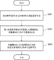
- 9 is a flow chart showing an operation example of the optical device according to the second embodiment of the present invention;
- FIG. 1 is a schematic diagram showing a configuration example of the optical device 1.
- FIG. 2A and 2B are diagrams showing an operation example of the optical device 1.
- FIG. 2A and 2B are diagrams showing an operation example of the optical device 1.
- the optical device 1 comprises a first optical fiber 10, a first reflecting means 20, a second reflecting means 30, and a second optical fiber 50. Further, the light emitted from the optical device 1 irradiates the object 40 and the reflected light from the object 40 is received. Also, the dotted lines shown in FIG. 1 indicate optical paths of light. Also, the first optical fiber 10 corresponds to a light emitting means. Also, the second optical fiber 50 corresponds to the light receiving means. The first optical fiber 10, the first reflecting means 20, the second reflecting means 30, and the second optical fiber 50 may be housed in the same housing.
- the first optical fiber 10 emits light output from a light source (not shown) from an emission surface 11 .
- Light emitted from the first optical fiber 10 enters the first reflecting means 20 .
- the light is, for example, pulsed laser light.
- the output face 11 is the core of the end face of the first optical fiber 10 .
- the first reflecting means 20 reflects the light emitted from the first optical fiber 10 and irradiates the object with parallel light. Specifically, the light reflected by the first reflecting means 20 is collimated and enters the object 40 after passing through an opening 31 which will be described later.
- the first reflecting means 20 is, for example, a reflective collimator.
- the first reflecting means 20 may be composed of a mirror and a collimator lens instead of the reflective collimator. In this case, the first reflecting means 20 reflects the light from the first optical fiber 10 with a mirror instead of reflecting light and emitting parallel light with one optical component as shown in FIG. Then, by passing the light reflected by the mirror through the collimator lens, parallel light is emitted to the opening 31 .
- the second reflecting means 30 has an opening 31 .
- the second reflecting means 30 allows the light reflected by the first reflecting means 20 to pass through the opening 31 .
- the second reflecting means 30 reflects the light emitted from the first reflecting means 20 toward the second optical fiber 50 .
- the second reflecting means 30 collects the reflected light from the object 40 and makes it enter the second optical fiber 50 .
- the second reflecting means 30 is, for example, a parabolic mirror capable of collecting reflected light.
- the opening 31 is a hole formed in the second reflecting means 30 .
- the second reflecting means 30 is arranged at a position where the reflected light from the first reflecting means 20 passes through the central portion of the opening 31 . As a result, even if the angle of the first reflecting means 20 is slightly shifted or the position of the second reflecting means 30 is shifted, the reflected light from the first reflecting means 20 is directed to the opening 31. can pass.
- the light receiving surface 51 of the second optical fiber 50 receives the light reflected by the second reflecting means 30 , which is reflected light from the object 40 .
- the second optical fiber 50 outputs the received light toward a light receiving element (not shown).
- the light receiving surface 51 is the core of the end surface of the second optical fiber 50 .
- FIG. Arrows 101 to 104 in FIG. 2 are for explaining the operation of the optical device 1 .
- first optical fiber 10 emits light to first reflecting means 20 .
- the first reflecting means 20 collimates the light from the first optical fiber 10 and reflects the collimated light toward the object 40 , as indicated by arrow 102 .
- the parallel light emitted from the first reflecting means 20 enters the object 40 through the opening 31 of the second reflecting means 30 .
- parallel light incident on object 40 is reflected by the surface of object 40 and enters second reflecting means 40 .
- the second reflecting means 30 emits reflected light incident from the object 40 toward the light receiving means 50 .
- the optical device 1 the light reflected by the first reflecting means 20 is output as parallel light. Therefore, the optical device 1 does not require an optical component for collimating light, such as a collimator lens, after the first reflecting means 20 .
- the parallel light with which the object 40 is irradiated passes through the opening of the second reflecting means 30, it does not enter the second reflecting means where the reflected light from the object is incident. Therefore, according to the optical device 1, the light output to the light-receiving element (not shown) through the second optical fiber 50 is less likely to include the parallel light that irradiates the object. As a result, the optical device 1 can cause the light receiving element or the like to accurately detect the intensity of the reflected light from the object.
- the position of the first optical fiber 10 can be freely changed by adjusting the angle of the first reflecting means 20.
- the position of the optical fiber 10 with respect to the opening 31 is restricted in order to allow the light irradiating the object 40 to pass through the opening 31 .
- the output surface 11 of the first optical fiber 10 is parallel to the light receiving surface 51 of the second optical fiber.
- One optical fiber may be provided. In this case, the first optical fiber 10 and the second optical fiber 50 extend in the same direction. optical fiber 10 and the second optical fiber 50 can be held. Therefore, the optical device 1 can have a simpler configuration than when the first optical fiber 10 and the second optical fiber 50 are held by different holding members.
- FIG. 3 is a drawing showing a schematic diagram of integrated reflecting means 60 in which the first reflecting means 20 and the second reflecting means 30 are integrated.
- the integrated reflecting means 60 comprises a first reflecting means 20 and a second reflecting means 30 .
- the second reflecting means 30 has an opening 31 as in FIG.
- the integral reflecting means 60 further comprises an aperture 21 .
- the light emitted from the first optical fiber 10 passes through the opening 21 , is reflected by the first reflecting means 20 , and is irradiated toward the object 40 . Reflected light from the object 40 is further reflected by the second reflecting means 30 and received by the second optical fiber 50 as in FIG. ⁇ Second embodiment>
- An optical device 2 according to the second embodiment will be described with reference to FIGS. 4 and 5.
- FIG. The optical device 2 comprises a first reflecting means 20 and a second reflecting means 30, as shown in FIG. Further, an object 40, a light emitting means 70 and a light receiving means 80 are arranged outside the optical device 2. As shown in FIG. Note that the optical device 2 may include at least one of the light emitting means 70 and the light receiving means 80 .
- the first reflecting means 20 reflects the light emitted from the light emitting means 70 and irradiates the object with parallel light.
- the first reflecting means 20 may have the same functions and connections as those of the first reflecting means 20 in the optical device 1 described above.
- the second reflecting means 30 reflects the reflected light generated by the parallel light reflected by the object 40 toward the light receiving means 80 .
- the second reflecting means 30 may have the same functions and connections as those of the second reflecting means 30 in the optical device 1 described above.
- the parallel light emitted by the first reflecting means 20 passes through the opening 31 provided in the second reflecting means 30 and enters the object 40 .
- the light emitting means 70 may be an optical fiber or a light source such as a laser.
- the light receiving means 80 may be an optical fiber or a light receiving element such as a PD (Photo Diode).
- the first reflecting means 20 reflects the light emitted from the light emitting means 70 and irradiates the object with parallel light (S201).
- the opening 31 allows the parallel light emitted by the first reflecting means 20 to pass toward the object 40 (S202).
- the second reflecting means 30 reflects the reflected light generated by the parallel light reflected by the object 40 toward the light receiving means 80 (S203).
- the light reflected by the first reflecting means 20 is output as parallel light. Therefore, the optical device 2 does not require an optical component for collimating light, such as a collimator lens, after the first reflecting means 20 .
- the parallel light irradiated to the object passes through the opening of the second reflecting means 30, it does not enter the second reflecting means 30 where the reflected light from the object is incident. Therefore, according to the optical device 2, the light output to the light-receiving element (not shown) through the second optical fiber 50 is less likely to include the parallel light that irradiates the object. As a result, the optical device 2 can cause the light receiving element or the like to accurately detect the intensity of the reflected light from the object.
- the optical device 2 since the optical device 2 includes the first reflecting means 20, the position of the light emitting means can be freely changed by adjusting the angle of the first reflecting means 20. Therefore, like the optical device 1, the optical device 2 can have a simple configuration.
Landscapes
- Engineering & Computer Science (AREA)
- Physics & Mathematics (AREA)
- Computer Networks & Wireless Communication (AREA)
- General Physics & Mathematics (AREA)
- Radar, Positioning & Navigation (AREA)
- Remote Sensing (AREA)
- Electromagnetism (AREA)
- Optical Radar Systems And Details Thereof (AREA)
Priority Applications (3)
| Application Number | Priority Date | Filing Date | Title |
|---|---|---|---|
| JP2023508298A JPWO2022201406A1 (https=) | 2021-03-25 | 2021-03-25 | |
| PCT/JP2021/012455 WO2022201406A1 (ja) | 2021-03-25 | 2021-03-25 | 光学装置及び光学装置の制御方法 |
| US18/268,544 US20240310493A1 (en) | 2021-03-25 | 2021-03-25 | Optical device and method for controlling optical device |
Applications Claiming Priority (1)
| Application Number | Priority Date | Filing Date | Title |
|---|---|---|---|
| PCT/JP2021/012455 WO2022201406A1 (ja) | 2021-03-25 | 2021-03-25 | 光学装置及び光学装置の制御方法 |
Publications (1)
| Publication Number | Publication Date |
|---|---|
| WO2022201406A1 true WO2022201406A1 (ja) | 2022-09-29 |
Family
ID=83395422
Family Applications (1)
| Application Number | Title | Priority Date | Filing Date |
|---|---|---|---|
| PCT/JP2021/012455 Ceased WO2022201406A1 (ja) | 2021-03-25 | 2021-03-25 | 光学装置及び光学装置の制御方法 |
Country Status (3)
| Country | Link |
|---|---|
| US (1) | US20240310493A1 (https=) |
| JP (1) | JPWO2022201406A1 (https=) |
| WO (1) | WO2022201406A1 (https=) |
Citations (6)
| Publication number | Priority date | Publication date | Assignee | Title |
|---|---|---|---|---|
| JP2009121836A (ja) * | 2007-11-12 | 2009-06-04 | Denso Wave Inc | レーザレーダ装置 |
| US7894044B1 (en) * | 2008-03-11 | 2011-02-22 | Oceanit Laboratories, Inc. | Laser for coherent LIDAR |
| JP2019039722A (ja) * | 2017-08-23 | 2019-03-14 | パナソニックIpマネジメント株式会社 | 距離測定装置 |
| CN109709572A (zh) * | 2019-02-01 | 2019-05-03 | 西安知微传感技术有限公司 | 一种半共轴光路接收激光雷达系统 |
| CN210038146U (zh) * | 2019-03-01 | 2020-02-07 | 深圳市大疆创新科技有限公司 | 测距模组、测距装置及可移动平台 |
| US20200174102A1 (en) * | 2018-11-30 | 2020-06-04 | Seagate Technology Llc | Large field of view measurement devices for lidar |
-
2021
- 2021-03-25 JP JP2023508298A patent/JPWO2022201406A1/ja active Pending
- 2021-03-25 WO PCT/JP2021/012455 patent/WO2022201406A1/ja not_active Ceased
- 2021-03-25 US US18/268,544 patent/US20240310493A1/en active Pending
Patent Citations (6)
| Publication number | Priority date | Publication date | Assignee | Title |
|---|---|---|---|---|
| JP2009121836A (ja) * | 2007-11-12 | 2009-06-04 | Denso Wave Inc | レーザレーダ装置 |
| US7894044B1 (en) * | 2008-03-11 | 2011-02-22 | Oceanit Laboratories, Inc. | Laser for coherent LIDAR |
| JP2019039722A (ja) * | 2017-08-23 | 2019-03-14 | パナソニックIpマネジメント株式会社 | 距離測定装置 |
| US20200174102A1 (en) * | 2018-11-30 | 2020-06-04 | Seagate Technology Llc | Large field of view measurement devices for lidar |
| CN109709572A (zh) * | 2019-02-01 | 2019-05-03 | 西安知微传感技术有限公司 | 一种半共轴光路接收激光雷达系统 |
| CN210038146U (zh) * | 2019-03-01 | 2020-02-07 | 深圳市大疆创新科技有限公司 | 测距模组、测距装置及可移动平台 |
Also Published As
| Publication number | Publication date |
|---|---|
| JPWO2022201406A1 (https=) | 2022-09-29 |
| US20240310493A1 (en) | 2024-09-19 |
Similar Documents
| Publication | Publication Date | Title |
|---|---|---|
| CN110376573B (zh) | 激光雷达装调系统及其装调方法 | |
| CN116710801A (zh) | 具有发射光功率监视器的LiDAR系统 | |
| JP3940806B2 (ja) | 光波測距装置 | |
| US11163095B2 (en) | Method of manufacturing an optical system including forming a plurality of diaphragm apertures from a screening element | |
| CN106291580A (zh) | 激光雷达成像系统 | |
| CN103415781A (zh) | 激光雷达 | |
| CN112204427B (zh) | 一种测距装置及移动平台 | |
| CN108681093A (zh) | 双光束激光准直系统 | |
| CN113544533A (zh) | Lidar发射器/接收器对准 | |
| US9945656B2 (en) | Multi-function spectroscopic device | |
| WO2022201406A1 (ja) | 光学装置及び光学装置の制御方法 | |
| JP2018514790A (ja) | 反射型目標物からの距離を光学的に測定する装置 | |
| EP3242079B1 (fr) | Module lumineux comportant un élément laser | |
| TW202208875A (zh) | 雷射光路系統及雷射雷達 | |
| CN112368596B (zh) | 光测距装置 | |
| CN119072614A (zh) | 光测定装置 | |
| JP2000121725A (ja) | 距離測定装置 | |
| JP4414183B2 (ja) | レーザ光送受光装置 | |
| CN115791688A (zh) | 一种透反射式太赫兹测量系统及方法 | |
| CN112368594B (zh) | 距离测定装置 | |
| JP7483016B2 (ja) | 測距装置 | |
| US11179800B2 (en) | Laser processing device | |
| JP2002350543A (ja) | レーザー距離計 | |
| JP7678288B2 (ja) | 距離計測装置 | |
| JPH07159534A (ja) | レーザ測距装置 |
Legal Events
| Date | Code | Title | Description |
|---|---|---|---|
| 121 | Ep: the epo has been informed by wipo that ep was designated in this application |
Ref document number: 21933016 Country of ref document: EP Kind code of ref document: A1 |
|
| WWE | Wipo information: entry into national phase |
Ref document number: 18268544 Country of ref document: US |
|
| ENP | Entry into the national phase |
Ref document number: 2023508298 Country of ref document: JP Kind code of ref document: A |
|
| NENP | Non-entry into the national phase |
Ref country code: DE |
|
| 122 | Ep: pct application non-entry in european phase |
Ref document number: 21933016 Country of ref document: EP Kind code of ref document: A1 |