WO2022201406A1 - Optical device and method for controlling optical device - Google Patents
Optical device and method for controlling optical device Download PDFInfo
- Publication number
- WO2022201406A1 WO2022201406A1 PCT/JP2021/012455 JP2021012455W WO2022201406A1 WO 2022201406 A1 WO2022201406 A1 WO 2022201406A1 JP 2021012455 W JP2021012455 W JP 2021012455W WO 2022201406 A1 WO2022201406 A1 WO 2022201406A1
- Authority
- WO
- WIPO (PCT)
- Prior art keywords
- light
- reflecting means
- optical device
- reflected
- optical fiber
- Prior art date
Links
- 230000003287 optical effect Effects 0.000 title claims abstract description 65
- 238000000034 method Methods 0.000 title claims abstract description 8
- 239000013307 optical fiber Substances 0.000 claims description 41
- 230000001678 irradiating effect Effects 0.000 claims description 4
- 238000005259 measurement Methods 0.000 abstract description 5
- 238000010586 diagram Methods 0.000 description 6
- 230000005540 biological transmission Effects 0.000 description 1
- 238000001514 detection method Methods 0.000 description 1
- 238000012986 modification Methods 0.000 description 1
- 230000004048 modification Effects 0.000 description 1
Images


Classifications
-
- G—PHYSICS
- G01—MEASURING; TESTING
- G01S—RADIO DIRECTION-FINDING; RADIO NAVIGATION; DETERMINING DISTANCE OR VELOCITY BY USE OF RADIO WAVES; LOCATING OR PRESENCE-DETECTING BY USE OF THE REFLECTION OR RERADIATION OF RADIO WAVES; ANALOGOUS ARRANGEMENTS USING OTHER WAVES
- G01S7/00—Details of systems according to groups G01S13/00, G01S15/00, G01S17/00
- G01S7/48—Details of systems according to groups G01S13/00, G01S15/00, G01S17/00 of systems according to group G01S17/00
- G01S7/481—Constructional features, e.g. arrangements of optical elements
Definitions
- the present invention relates to an optical device that enables more accurate measurement by LiDAR (Light Detection and Ranging) and a control method for the optical device.
- LiDAR Light Detection and Ranging
- Patent Literature 1 discloses a technique of performing measurement by LiDAR.
- a configuration may be used in which a transmitting optical system that emits light and a receiving optical system that receives reflected light from an object are integrated.
- the light emitted from the transmission optical system and the reflected light received by the reception optical system enter the same lens.
- the receiving optical system receives not only the reflected light from the object but also the light reflected by the lens after being emitted from the transmitting optical system, so the intensity of the reflected light from the object can be accurately detected. Sometimes I could't.
- the present invention has been made in view of the above problems, and an object of the present invention is to provide an optical device capable of more accurate measurement by LiDAR and a method of controlling the optical device.
- the optical device of the present invention is a first reflecting means for reflecting the light emitted from the light emitting means and irradiating the object as parallel irradiation light; a second reflecting means for reflecting the irradiation light reflected by the object toward the light receiving means; The irradiation light reflected by the first reflecting means passes through an opening provided in the second reflecting means and is irradiated onto the object.
- the method for controlling an optical device of the present invention includes: Reflecting the light emitted from the light emitting means and irradiating the object as parallel irradiation light, causing the irradiation light reflected by the first reflecting means to pass through an opening provided in the second reflecting means; The irradiation light reflected by the object is reflected toward the light receiving means.
- an optical device capable of accurate measurement using LiDAR and a control method for the optical device.
- FIG. 1 is a schematic diagram of an optical device according to a first embodiment of the present invention
- FIG. 4A and 4B are diagrams for explaining the operation of the optical device according to the first embodiment of the present invention
- FIG. It is a figure which shows the structural example of the modification of the optical apparatus in the 1st Embodiment of this invention.
- FIG. 5 is a block diagram showing a configuration example of an optical device according to a second embodiment of the present invention
- 9 is a flow chart showing an operation example of the optical device according to the second embodiment of the present invention;
- FIG. 1 is a schematic diagram showing a configuration example of the optical device 1.
- FIG. 2A and 2B are diagrams showing an operation example of the optical device 1.
- FIG. 2A and 2B are diagrams showing an operation example of the optical device 1.
- the optical device 1 comprises a first optical fiber 10, a first reflecting means 20, a second reflecting means 30, and a second optical fiber 50. Further, the light emitted from the optical device 1 irradiates the object 40 and the reflected light from the object 40 is received. Also, the dotted lines shown in FIG. 1 indicate optical paths of light. Also, the first optical fiber 10 corresponds to a light emitting means. Also, the second optical fiber 50 corresponds to the light receiving means. The first optical fiber 10, the first reflecting means 20, the second reflecting means 30, and the second optical fiber 50 may be housed in the same housing.
- the first optical fiber 10 emits light output from a light source (not shown) from an emission surface 11 .
- Light emitted from the first optical fiber 10 enters the first reflecting means 20 .
- the light is, for example, pulsed laser light.
- the output face 11 is the core of the end face of the first optical fiber 10 .
- the first reflecting means 20 reflects the light emitted from the first optical fiber 10 and irradiates the object with parallel light. Specifically, the light reflected by the first reflecting means 20 is collimated and enters the object 40 after passing through an opening 31 which will be described later.
- the first reflecting means 20 is, for example, a reflective collimator.
- the first reflecting means 20 may be composed of a mirror and a collimator lens instead of the reflective collimator. In this case, the first reflecting means 20 reflects the light from the first optical fiber 10 with a mirror instead of reflecting light and emitting parallel light with one optical component as shown in FIG. Then, by passing the light reflected by the mirror through the collimator lens, parallel light is emitted to the opening 31 .
- the second reflecting means 30 has an opening 31 .
- the second reflecting means 30 allows the light reflected by the first reflecting means 20 to pass through the opening 31 .
- the second reflecting means 30 reflects the light emitted from the first reflecting means 20 toward the second optical fiber 50 .
- the second reflecting means 30 collects the reflected light from the object 40 and makes it enter the second optical fiber 50 .
- the second reflecting means 30 is, for example, a parabolic mirror capable of collecting reflected light.
- the opening 31 is a hole formed in the second reflecting means 30 .
- the second reflecting means 30 is arranged at a position where the reflected light from the first reflecting means 20 passes through the central portion of the opening 31 . As a result, even if the angle of the first reflecting means 20 is slightly shifted or the position of the second reflecting means 30 is shifted, the reflected light from the first reflecting means 20 is directed to the opening 31. can pass.
- the light receiving surface 51 of the second optical fiber 50 receives the light reflected by the second reflecting means 30 , which is reflected light from the object 40 .
- the second optical fiber 50 outputs the received light toward a light receiving element (not shown).
- the light receiving surface 51 is the core of the end surface of the second optical fiber 50 .
- FIG. Arrows 101 to 104 in FIG. 2 are for explaining the operation of the optical device 1 .
- first optical fiber 10 emits light to first reflecting means 20 .
- the first reflecting means 20 collimates the light from the first optical fiber 10 and reflects the collimated light toward the object 40 , as indicated by arrow 102 .
- the parallel light emitted from the first reflecting means 20 enters the object 40 through the opening 31 of the second reflecting means 30 .
- parallel light incident on object 40 is reflected by the surface of object 40 and enters second reflecting means 40 .
- the second reflecting means 30 emits reflected light incident from the object 40 toward the light receiving means 50 .
- the optical device 1 the light reflected by the first reflecting means 20 is output as parallel light. Therefore, the optical device 1 does not require an optical component for collimating light, such as a collimator lens, after the first reflecting means 20 .
- the parallel light with which the object 40 is irradiated passes through the opening of the second reflecting means 30, it does not enter the second reflecting means where the reflected light from the object is incident. Therefore, according to the optical device 1, the light output to the light-receiving element (not shown) through the second optical fiber 50 is less likely to include the parallel light that irradiates the object. As a result, the optical device 1 can cause the light receiving element or the like to accurately detect the intensity of the reflected light from the object.
- the position of the first optical fiber 10 can be freely changed by adjusting the angle of the first reflecting means 20.
- the position of the optical fiber 10 with respect to the opening 31 is restricted in order to allow the light irradiating the object 40 to pass through the opening 31 .
- the output surface 11 of the first optical fiber 10 is parallel to the light receiving surface 51 of the second optical fiber.
- One optical fiber may be provided. In this case, the first optical fiber 10 and the second optical fiber 50 extend in the same direction. optical fiber 10 and the second optical fiber 50 can be held. Therefore, the optical device 1 can have a simpler configuration than when the first optical fiber 10 and the second optical fiber 50 are held by different holding members.
- FIG. 3 is a drawing showing a schematic diagram of integrated reflecting means 60 in which the first reflecting means 20 and the second reflecting means 30 are integrated.
- the integrated reflecting means 60 comprises a first reflecting means 20 and a second reflecting means 30 .
- the second reflecting means 30 has an opening 31 as in FIG.
- the integral reflecting means 60 further comprises an aperture 21 .
- the light emitted from the first optical fiber 10 passes through the opening 21 , is reflected by the first reflecting means 20 , and is irradiated toward the object 40 . Reflected light from the object 40 is further reflected by the second reflecting means 30 and received by the second optical fiber 50 as in FIG. ⁇ Second embodiment>
- An optical device 2 according to the second embodiment will be described with reference to FIGS. 4 and 5.
- FIG. The optical device 2 comprises a first reflecting means 20 and a second reflecting means 30, as shown in FIG. Further, an object 40, a light emitting means 70 and a light receiving means 80 are arranged outside the optical device 2. As shown in FIG. Note that the optical device 2 may include at least one of the light emitting means 70 and the light receiving means 80 .
- the first reflecting means 20 reflects the light emitted from the light emitting means 70 and irradiates the object with parallel light.
- the first reflecting means 20 may have the same functions and connections as those of the first reflecting means 20 in the optical device 1 described above.
- the second reflecting means 30 reflects the reflected light generated by the parallel light reflected by the object 40 toward the light receiving means 80 .
- the second reflecting means 30 may have the same functions and connections as those of the second reflecting means 30 in the optical device 1 described above.
- the parallel light emitted by the first reflecting means 20 passes through the opening 31 provided in the second reflecting means 30 and enters the object 40 .
- the light emitting means 70 may be an optical fiber or a light source such as a laser.
- the light receiving means 80 may be an optical fiber or a light receiving element such as a PD (Photo Diode).
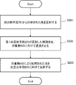
- the first reflecting means 20 reflects the light emitted from the light emitting means 70 and irradiates the object with parallel light (S201).
- the opening 31 allows the parallel light emitted by the first reflecting means 20 to pass toward the object 40 (S202).
- the second reflecting means 30 reflects the reflected light generated by the parallel light reflected by the object 40 toward the light receiving means 80 (S203).
- the light reflected by the first reflecting means 20 is output as parallel light. Therefore, the optical device 2 does not require an optical component for collimating light, such as a collimator lens, after the first reflecting means 20 .
- the parallel light irradiated to the object passes through the opening of the second reflecting means 30, it does not enter the second reflecting means 30 where the reflected light from the object is incident. Therefore, according to the optical device 2, the light output to the light-receiving element (not shown) through the second optical fiber 50 is less likely to include the parallel light that irradiates the object. As a result, the optical device 2 can cause the light receiving element or the like to accurately detect the intensity of the reflected light from the object.
- the optical device 2 since the optical device 2 includes the first reflecting means 20, the position of the light emitting means can be freely changed by adjusting the angle of the first reflecting means 20. Therefore, like the optical device 1, the optical device 2 can have a simple configuration.
Abstract
[Problem] To provide an optical device and a method for controlling said optical device which enable more accurate measurement by using LiDAR. [Solution] This optical device is provided with: a first reflection means that reflects light emitted from a light emission means and irradiates an object with the reflected light as irradiation light; and a second reflection means that reflects the irradiation light reflected by the object toward a light reception means. The irradiation light reflected by the first reflection means passes through an opening part provided to the second reflection means and is applied to the object.
Description
本発明は、LiDAR(Light Detection and Ranging)によって、より正確な測定を可能にする光学装置及び光学装置の制御方法に関する。
The present invention relates to an optical device that enables more accurate measurement by LiDAR (Light Detection and Ranging) and a control method for the optical device.
近年、光を対象物に対して出射し、対象物から受光した反射光に基づいて、対象物の表面状態等を検出するLiDARと呼ばれる技術が用いられている。例えば、特許文献1にLiDARによる測定を行う技術が開示されている。
In recent years, a technology called LiDAR has been used that emits light to an object and detects the surface state of the object based on the reflected light received from the object. For example, Patent Literature 1 discloses a technique of performing measurement by LiDAR.
LiDARにおいては、光を出射する送信光学系と対象物からの反射光を受光する受信光学系が一体化された構成が用いられる場合がある。当該構成において、送信光学系から出射される光と受信光学系が受光する反射光は、同一のレンズに入射する。
In LiDAR, a configuration may be used in which a transmitting optical system that emits light and a receiving optical system that receives reflected light from an object are integrated. In this configuration, the light emitted from the transmission optical system and the reflected light received by the reception optical system enter the same lens.
この際、受信光学系は、対象物からの反射光だけでなく、送信光学系から出射された後、レンズで反射された光も受光するため、対象物からの反射光の強度を正確に検出できない場合があった。
At this time, the receiving optical system receives not only the reflected light from the object but also the light reflected by the lens after being emitted from the transmitting optical system, so the intensity of the reflected light from the object can be accurately detected. Sometimes I couldn't.
本発明は、上記問題に鑑みてなされたものであり、本発明の目的は、LiDARにより、より正確な測定が可能な光学装置及び光学装置の制御方法を提供することである。
The present invention has been made in view of the above problems, and an object of the present invention is to provide an optical device capable of more accurate measurement by LiDAR and a method of controlling the optical device.
本発明の光学装置は、
光出射手段から出射された光を反射させ、平行な照射光として物体に向けて照射する第1の反射手段と、
前記物体により反射された前記照射光を受光手段に向けて反射させる第2の反射手段と、を備え、
前記第1の反射手段が反射した照射光は、前記第2の反射手段に設けられた開口部を通過して、前記物体に照射される。 The optical device of the present invention is
a first reflecting means for reflecting the light emitted from the light emitting means and irradiating the object as parallel irradiation light;
a second reflecting means for reflecting the irradiation light reflected by the object toward the light receiving means;
The irradiation light reflected by the first reflecting means passes through an opening provided in the second reflecting means and is irradiated onto the object.
または、本発明の光学装置の制御方法は、
光出射手段から出射された光を反射させ、平行な照射光として物体に向けて照射し、
前記第1の反射手段が反射した照射光に、前記第2の反射手段に設けられた開口部を通過させ、
前記物体により反射された前記照射光を受光手段に向けて反射させる。 Alternatively, the method for controlling an optical device of the present invention includes:
Reflecting the light emitted from the light emitting means and irradiating the object as parallel irradiation light,
causing the irradiation light reflected by the first reflecting means to pass through an opening provided in the second reflecting means;
The irradiation light reflected by the object is reflected toward the light receiving means.
本発明によれば、LiDARにより正確な測定が可能な光学装置及び光学装置の制御方法を提供することが可能である。
According to the present invention, it is possible to provide an optical device capable of accurate measurement using LiDAR and a control method for the optical device.
<第1の実施形態>
第1の実施形態における光学装置1について、図1及び図2に基づき説明する。図1は、光学装置1の構成例を示す模式図である。また、図2は、光学装置1の動作例を示す図である。 <First embodiment>
An optical device 1 according to the first embodiment will be described with reference to FIGS. 1 and 2. FIG. FIG. 1 is a schematic diagram showing a configuration example of the optical device 1. As shown in FIG. 2A and 2B are diagrams showing an operation example of the optical device 1. FIG.
図1に示されるように、光学装置1は、第1の光ファイバ10、第1の反射手段20、第2の反射手段30、第2の光ファイバ50を備える。また、光学装置1から出射された光は対象物40に光を照射し、対象物40からの反射光を受光する。また、図1に示される点線は、光の光路を示す。また、第1の光ファイバ10は、光出射手段に対応する。また、第2の光ファイバ50は、受光手段に対応する。なお、第1の光ファイバ10、第1の反射手段20、第2の反射手段30、第2の光ファイバ50は同一の筐体に格納されていても良い。
As shown in FIG. 1, the optical device 1 comprises a first optical fiber 10, a first reflecting means 20, a second reflecting means 30, and a second optical fiber 50. Further, the light emitted from the optical device 1 irradiates the object 40 and the reflected light from the object 40 is received. Also, the dotted lines shown in FIG. 1 indicate optical paths of light. Also, the first optical fiber 10 corresponds to a light emitting means. Also, the second optical fiber 50 corresponds to the light receiving means. The first optical fiber 10, the first reflecting means 20, the second reflecting means 30, and the second optical fiber 50 may be housed in the same housing.
第1の光ファイバ10は、不図示の光源から出力された光を、出射面11から出射する。第1の光ファイバ10から出射された光は、第1の反射手段20に入射する。光とは、例えば、パルス状のレーザ光である。出射面11は、第1の光ファイバ10の端面のコアである。
The first optical fiber 10 emits light output from a light source (not shown) from an emission surface 11 . Light emitted from the first optical fiber 10 enters the first reflecting means 20 . The light is, for example, pulsed laser light. The output face 11 is the core of the end face of the first optical fiber 10 .
第1の反射手段20は、第1の光ファイバ10から出射された光を反射し、平行光を物体に向けて照射する。具体的には、第1の反射手段20で反射された光は平行光にされ、後述の開口部31を通過した後で、対象物40に入射する。第1の反射手段20は、例えば、反射型コリメータである。なお、第1の反射手段20は、反射型コリメータでなく、ミラーとコリメータレンズにより構成されても良い。この場合、第1の反射手段20は、図1に示されるように一つの光学部品により光の反射と平行光の出射を行うのではなく、ミラーにより第1の光ファイバ10からの光を反射し、ミラーで反射した光をコリメータレンズに通過させることにより、平行光を開口部31に対して出射する。
The first reflecting means 20 reflects the light emitted from the first optical fiber 10 and irradiates the object with parallel light. Specifically, the light reflected by the first reflecting means 20 is collimated and enters the object 40 after passing through an opening 31 which will be described later. The first reflecting means 20 is, for example, a reflective collimator. The first reflecting means 20 may be composed of a mirror and a collimator lens instead of the reflective collimator. In this case, the first reflecting means 20 reflects the light from the first optical fiber 10 with a mirror instead of reflecting light and emitting parallel light with one optical component as shown in FIG. Then, by passing the light reflected by the mirror through the collimator lens, parallel light is emitted to the opening 31 .
第2の反射手段30は、開口部31を備える。第2の反射手段30は、第1の反射手段20で反射された光を開口部31に通過させる。また、第2の反射手段30は、第1の反射手段20から照射された光が対象物40により反射することにより生じた反射光を、第2の光ファイバ50に向けて反射する。この際、第2の反射手段30は、対象物40からの反射光を集光して、第2の光ファイバ50に入射させる。第2の反射手段30は、例えば、反射光を集光可能な放物面ミラーである。開口部31は、第2の反射手段30に形成された孔である。
The second reflecting means 30 has an opening 31 . The second reflecting means 30 allows the light reflected by the first reflecting means 20 to pass through the opening 31 . Also, the second reflecting means 30 reflects the light emitted from the first reflecting means 20 toward the second optical fiber 50 . At this time, the second reflecting means 30 collects the reflected light from the object 40 and makes it enter the second optical fiber 50 . The second reflecting means 30 is, for example, a parabolic mirror capable of collecting reflected light. The opening 31 is a hole formed in the second reflecting means 30 .
なお、第2の反射手段30は、第1の反射手段20からの反射光が開口部31の中心部を通過する位置に配置される。これにより、第1の反射手段20の角度が僅かにずれたり、第2の反射手段30の位置がずれたりした場合であっても、第1の反射手段20からの反射光を開口部31に通過させることができる。
The second reflecting means 30 is arranged at a position where the reflected light from the first reflecting means 20 passes through the central portion of the opening 31 . As a result, even if the angle of the first reflecting means 20 is slightly shifted or the position of the second reflecting means 30 is shifted, the reflected light from the first reflecting means 20 is directed to the opening 31. can pass.
第2の光ファイバ50は、対象物40からの反射光であって、第2の反射手段30により反射された光を受光面51により受光する。第2の光ファイバ50は、受光した光を不図示の受光素子に向けて出力する。受光面51は、第2の光ファイバ50の端面のコアである。
The light receiving surface 51 of the second optical fiber 50 receives the light reflected by the second reflecting means 30 , which is reflected light from the object 40 . The second optical fiber 50 outputs the received light toward a light receiving element (not shown). The light receiving surface 51 is the core of the end surface of the second optical fiber 50 .
次に図2を用いて、光学装置1の動作について説明する。図2における矢印101~104は、光学装置1の動作を説明するためのものである。
Next, the operation of the optical device 1 will be described using FIG. Arrows 101 to 104 in FIG. 2 are for explaining the operation of the optical device 1 .
矢印101に示されるように、第1の光ファイバ10は、光を第1の反射手段20に出射する。矢印102に示されるように、第1の反射手段20は、第1の光ファイバ10からの光を平行化して、平行光を対象物40に向けて反射する。この際、第1の反射手段20から出射された平行光は、第2の反射手段30の開口部31を介して、対象物40に入射する。矢印103に示されるように、対象物40に入射した平行光は、対象物40の表面で反射され、第2の反射手段40に入射する。矢印104に示されるように、第2の反射手段30は、対象物40から入射した反射光を、受光手段50に向けて出射する。
As indicated by arrow 101 , first optical fiber 10 emits light to first reflecting means 20 . The first reflecting means 20 collimates the light from the first optical fiber 10 and reflects the collimated light toward the object 40 , as indicated by arrow 102 . At this time, the parallel light emitted from the first reflecting means 20 enters the object 40 through the opening 31 of the second reflecting means 30 . As indicated by arrow 103 , parallel light incident on object 40 is reflected by the surface of object 40 and enters second reflecting means 40 . As indicated by an arrow 104 , the second reflecting means 30 emits reflected light incident from the object 40 toward the light receiving means 50 .
以上のように、光学装置1においては、第1の反射手段20により反射された光が、平行光として出力される。そのため、光学装置1は、第1の反射手段20よりも後段にコリメータレンズなどの光を平行化するための光学部品を必要としない。また、対象物40に照射される平行光は、第2の反射手段30の開口部を通過するため、対象物からの反射光が入射する第2の反射手段に入射することがない。そのため、光学装置1によれば、第2の光ファイバ50を介して不図示の受光素子に出力される光に、対象物に照射される平行光が含まれにくい。この結果、光学装置1は、対象物からの反射光の強度を、受光素子などに正確に検出させることが可能である。
As described above, in the optical device 1, the light reflected by the first reflecting means 20 is output as parallel light. Therefore, the optical device 1 does not require an optical component for collimating light, such as a collimator lens, after the first reflecting means 20 . In addition, since the parallel light with which the object 40 is irradiated passes through the opening of the second reflecting means 30, it does not enter the second reflecting means where the reflected light from the object is incident. Therefore, according to the optical device 1, the light output to the light-receiving element (not shown) through the second optical fiber 50 is less likely to include the parallel light that irradiates the object. As a result, the optical device 1 can cause the light receiving element or the like to accurately detect the intensity of the reflected light from the object.
また、光学装置1は、第1の反射手段20を備えているため、第1の反射手段20の角度を調整することで、第1の光ファイバ10の位置を自由に変化させることができる。例えば、第1の反射手段20が無い場合は、対象物40に照射する光を開口部31に通過させるために、開口部31に対する光ファイバ10の位置は制限される。しかし、第1の反射手段20を備えることにより、図1に示されるように、第1の光ファイバ10の出射面11が、第2の光ファイバの受光面51と平行になるように、第1の光ファイバを設けることができる。この場合、第1の光ファイバ10及び第2の光ファイバ50は同じ方向に延びるため、第1の光ファイバ10及び第2の光ファイバ50が延びる方向に位置する同一の保持部材により、第1の光ファイバ10及び第2の光ファイバ50を保持することができる。そのため、光学装置1は、第1の光ファイバ10及び第2の光ファイバ50を異なる保持部材により保持する場合に比べて、構成を簡素にすることができる。
In addition, since the optical device 1 includes the first reflecting means 20, the position of the first optical fiber 10 can be freely changed by adjusting the angle of the first reflecting means 20. For example, in the absence of the first reflecting means 20 , the position of the optical fiber 10 with respect to the opening 31 is restricted in order to allow the light irradiating the object 40 to pass through the opening 31 . However, by providing the first reflecting means 20, as shown in FIG. 1, the output surface 11 of the first optical fiber 10 is parallel to the light receiving surface 51 of the second optical fiber. One optical fiber may be provided. In this case, the first optical fiber 10 and the second optical fiber 50 extend in the same direction. optical fiber 10 and the second optical fiber 50 can be held. Therefore, the optical device 1 can have a simpler configuration than when the first optical fiber 10 and the second optical fiber 50 are held by different holding members.
なお、図1の説明においては、第1の反射手段20及び第2の反射手段30は、異なる光学部品として記載されているが、一体に設けられていても良い。図3は、第1の反射手段20及び第2の反射手段30を一体にした、一体型反射手段60の模式図を示す図面である。一体型反射手段60は、第1の反射手段20、第2の反射手段30を備える。また、第2の反射手段30は、図1と同様に、開口部31を備える。一体型反射手段60は、更に開口部21を備える。
Although the first reflecting means 20 and the second reflecting means 30 are described as different optical components in the description of FIG. 1, they may be integrally provided. FIG. 3 is a drawing showing a schematic diagram of integrated reflecting means 60 in which the first reflecting means 20 and the second reflecting means 30 are integrated. The integrated reflecting means 60 comprises a first reflecting means 20 and a second reflecting means 30 . Also, the second reflecting means 30 has an opening 31 as in FIG. The integral reflecting means 60 further comprises an aperture 21 .
一体型反射手段60においては、第1の光ファイバ10から出射された光は開口部21を通過し、第1の反射手段20により反射されて対象物40に向けて照射される。対象物40からの反射光は、第2の反射手段30によりさらに反射され、図1と同様に第2の光ファイバ50により受光される。
<第2の実施形態>
第2の実施形態における光学装置2について、図4及び図5に基づいて説明する。光学装置2は、図4に示されるように、第1の反射手段20及び第2の反射手段30を備える。また、光学装置2の外部には、対象物40、光出射手段70及び受光手段80が配置されている。なお、光学装置2は、光出射手段70及び受光手段80の少なくとも一つを含んでいても良い。 In the integrated reflecting means 60 , the light emitted from the firstoptical fiber 10 passes through the opening 21 , is reflected by the first reflecting means 20 , and is irradiated toward the object 40 . Reflected light from the object 40 is further reflected by the second reflecting means 30 and received by the second optical fiber 50 as in FIG.
<Second embodiment>
An optical device 2 according to the second embodiment will be described with reference to FIGS. 4 and 5. FIG. The optical device 2 comprises a first reflecting means 20 and a second reflecting means 30, as shown in FIG. Further, anobject 40, a light emitting means 70 and a light receiving means 80 are arranged outside the optical device 2. As shown in FIG. Note that the optical device 2 may include at least one of the light emitting means 70 and the light receiving means 80 .
<第2の実施形態>
第2の実施形態における光学装置2について、図4及び図5に基づいて説明する。光学装置2は、図4に示されるように、第1の反射手段20及び第2の反射手段30を備える。また、光学装置2の外部には、対象物40、光出射手段70及び受光手段80が配置されている。なお、光学装置2は、光出射手段70及び受光手段80の少なくとも一つを含んでいても良い。 In the integrated reflecting means 60 , the light emitted from the first
<Second embodiment>
An optical device 2 according to the second embodiment will be described with reference to FIGS. 4 and 5. FIG. The optical device 2 comprises a first reflecting means 20 and a second reflecting means 30, as shown in FIG. Further, an
第1の反射手段20は、光出射手段70から出射された光を反射し、平行光を物体に向けて照射する。第1の反射手段20は、上述の光学装置1における第1の反射手段20と同様の機能及び接続関係を備えていても良い。
The first reflecting means 20 reflects the light emitted from the light emitting means 70 and irradiates the object with parallel light. The first reflecting means 20 may have the same functions and connections as those of the first reflecting means 20 in the optical device 1 described above.
第2の反射手段30は、平行光が対象物40により反射して生じた反射光を受光手段80に向けて反射する。第2の反射手段30は、上述の光学装置1における第2の反射手段30と同様の機能及び接続関係を備えていても良い。
The second reflecting means 30 reflects the reflected light generated by the parallel light reflected by the object 40 toward the light receiving means 80 . The second reflecting means 30 may have the same functions and connections as those of the second reflecting means 30 in the optical device 1 described above.
光学装置2において、第1の反射手段20が照射した平行光は、第2の反射手段30に設けられた開口部31を通過して、対象物40に入射する。
In the optical device 2 , the parallel light emitted by the first reflecting means 20 passes through the opening 31 provided in the second reflecting means 30 and enters the object 40 .
なお、光出射手段70は、光ファイバであっても良いし、レーザなどの光源であっても良い。また、受光手段80は、光ファイバであってもよいし、PD(Photo Diode)などの受光素子であっても良い。
The light emitting means 70 may be an optical fiber or a light source such as a laser. Also, the light receiving means 80 may be an optical fiber or a light receiving element such as a PD (Photo Diode).
次に、光学装置2の動作について、図5に基づき説明する。
Next, the operation of the optical device 2 will be explained based on FIG.
第1の反射手段20は、光出射手段70から出射された光を反射し、平行光を物体に向けて照射する(S201)。開口部31は、第1の反射手段20が照射した平行光を、対象物40に向けて通過させる(S202)。第2の反射手段30は、平行光が対象物40により反射して生じた反射光を受光手段80に向けて反射する(S203)。
The first reflecting means 20 reflects the light emitted from the light emitting means 70 and irradiates the object with parallel light (S201). The opening 31 allows the parallel light emitted by the first reflecting means 20 to pass toward the object 40 (S202). The second reflecting means 30 reflects the reflected light generated by the parallel light reflected by the object 40 toward the light receiving means 80 (S203).
このように、光学装置2においては、第1の反射手段20により反射された光が、平行光として出力される。そのため、光学装置2は、第1の反射手段20よりも後段にコリメータレンズなどの光を平行化するための光学部品を必要としない。また、対象物に照射される平行光は、第2の反射手段30の開口部を通過するため、対象物からの反射光が入射する第2の反射手段30に入射することがない。そのため、光学装置2によれば、第2の光ファイバ50を介して不図示の受光素子に出力される光に、対象物に照射される平行光が含まれにくい。この結果、光学装置2は、対象物からの反射光の強度を、受光素子などに正確に検出させることが可能である。
Thus, in the optical device 2, the light reflected by the first reflecting means 20 is output as parallel light. Therefore, the optical device 2 does not require an optical component for collimating light, such as a collimator lens, after the first reflecting means 20 . In addition, since the parallel light irradiated to the object passes through the opening of the second reflecting means 30, it does not enter the second reflecting means 30 where the reflected light from the object is incident. Therefore, according to the optical device 2, the light output to the light-receiving element (not shown) through the second optical fiber 50 is less likely to include the parallel light that irradiates the object. As a result, the optical device 2 can cause the light receiving element or the like to accurately detect the intensity of the reflected light from the object.
また、光学装置2は、第1の反射手段20を備えているため、第1の反射手段20の角度を調整することで、光出射手段の位置を自由に変化させることができる。そのため、光学装置1と同様に、光学装置2は、構成を簡素にすることができる。
In addition, since the optical device 2 includes the first reflecting means 20, the position of the light emitting means can be freely changed by adjusting the angle of the first reflecting means 20. Therefore, like the optical device 1, the optical device 2 can have a simple configuration.
以上、実施形態を参照して本願発明を説明したが、本願発明は上記実施形態に限定されるものではない。本願発明の構成や詳細には、本願発明のスコープ内で当業者が理解し得る様々な変更をすることができる。
Although the present invention has been described with reference to the embodiments, the present invention is not limited to the above embodiments. Various changes that can be understood by those skilled in the art can be made to the configuration and details of the present invention within the scope of the present invention.
1、2 光学装置
10 第1の光ファイバ
11 出射面
20 第1の反射手段
30 第2の反射手段
21、31 開口部
40 対象物
50 第2の光ファイバ
51 受光面
60 一体型反射手段
70 光出射手段
80 受光手段 1, 2Optical device 10 First optical fiber 11 Output surface 20 First reflecting means 30 Second reflecting means 21, 31 Opening 40 Object 50 Second optical fiber 51 Light receiving surface 60 Integrated reflecting means 70 Light Emitting means 80 Light receiving means
10 第1の光ファイバ
11 出射面
20 第1の反射手段
30 第2の反射手段
21、31 開口部
40 対象物
50 第2の光ファイバ
51 受光面
60 一体型反射手段
70 光出射手段
80 受光手段 1, 2
Claims (7)
- 光出射手段から出射された光を反射し、平行光を物体に向けて照射する第1の反射手段と、
前記平行光が前記物体により反射して生じた反射光を受光手段に向けて反射させる第2の反射手段と、を備え、
前記第1の反射手段が照射した平行光は、前記第2の反射手段に設けられた開口部を通過して、前記物体に入射する光学装置。 a first reflecting means for reflecting the light emitted from the light emitting means and irradiating the object with parallel light;
a second reflecting means for reflecting the reflected light generated by the parallel light reflected by the object toward the light receiving means;
The optical device according to claim 1, wherein the parallel light irradiated by the first reflecting means passes through an opening provided in the second reflecting means and is incident on the object. - 前記第1の反射手段は、前記開口部の中心部を前記平行光に通過させる、請求項1に記載の光学装置。 The optical device according to claim 1, wherein the first reflecting means allows the parallel light to pass through the central portion of the opening.
- 前記第1の反射手段及び前記第2の反射手段は、同一の筐体に収容されている請求項1又は2の何れか1項に記載の光学装置。 The optical device according to claim 1 or 2, wherein the first reflecting means and the second reflecting means are housed in the same housing.
- 前記光出射手段から出射された前記光は、パルス波である請求項1から3の何れか1項に記載の光学装置。 The optical device according to any one of claims 1 to 3, wherein the light emitted from the light emitting means is a pulse wave.
- 前記光出射手段は、第1の光ファイバの端面であり、
前記受光手段は、第2の光ファイバの端面である請求項1から4の何れか1項に記載の光学装置。 The light emitting means is an end surface of the first optical fiber,
5. The optical device according to any one of claims 1 to 4, wherein the light receiving means is an end face of the second optical fiber. - 前記第1の光ファイバ及び前記第2の光ファイバは、互いに平行に設けられている請求項1から5の何れか1項に記載の光学装置。 The optical device according to any one of claims 1 to 5, wherein the first optical fiber and the second optical fiber are provided parallel to each other.
- 光出射手段から出射された光を第1の反射手段により反射させ、平行光を物体に向けて照射し、
前記第1の反射手段が照射した前記平行光に、第2の反射手段に設けられた開口部を通過させ、
前記平行光が前記物体により反射して生じた反射光を、前記第2の反射手段により受光手段に向けて反射させる、
光学装置の制御方法。 The light emitted from the light emitting means is reflected by the first reflecting means, and the object is irradiated with parallel light,
causing the parallel light emitted by the first reflecting means to pass through an opening provided in the second reflecting means;
The reflected light generated by the parallel light reflected by the object is reflected toward the light receiving means by the second reflecting means.
A method of controlling an optical device.
Priority Applications (2)
| Application Number | Priority Date | Filing Date | Title |
|---|---|---|---|
| PCT/JP2021/012455 WO2022201406A1 (en) | 2021-03-25 | 2021-03-25 | Optical device and method for controlling optical device |
| JP2023508298A JPWO2022201406A1 (en) | 2021-03-25 | 2021-03-25 |
Applications Claiming Priority (1)
| Application Number | Priority Date | Filing Date | Title |
|---|---|---|---|
| PCT/JP2021/012455 WO2022201406A1 (en) | 2021-03-25 | 2021-03-25 | Optical device and method for controlling optical device |
Publications (1)
| Publication Number | Publication Date |
|---|---|
| WO2022201406A1 true WO2022201406A1 (en) | 2022-09-29 |
Family
ID=83395422
Family Applications (1)
| Application Number | Title | Priority Date | Filing Date |
|---|---|---|---|
| PCT/JP2021/012455 WO2022201406A1 (en) | 2021-03-25 | 2021-03-25 | Optical device and method for controlling optical device |
Country Status (2)
| Country | Link |
|---|---|
| JP (1) | JPWO2022201406A1 (en) |
| WO (1) | WO2022201406A1 (en) |
Citations (6)
| Publication number | Priority date | Publication date | Assignee | Title |
|---|---|---|---|---|
| JP2009121836A (en) * | 2007-11-12 | 2009-06-04 | Denso Wave Inc | Laser radar apparatus |
| US7894044B1 (en) * | 2008-03-11 | 2011-02-22 | Oceanit Laboratories, Inc. | Laser for coherent LIDAR |
| JP2019039722A (en) * | 2017-08-23 | 2019-03-14 | パナソニックIpマネジメント株式会社 | Distance measuring device |
| CN109709572A (en) * | 2019-02-01 | 2019-05-03 | 西安知微传感技术有限公司 | A kind of half coaxial optical path reception laser radar system |
| CN210038146U (en) * | 2019-03-01 | 2020-02-07 | 深圳市大疆创新科技有限公司 | Distance measurement module, distance measurement device and movable platform |
| US20200174102A1 (en) * | 2018-11-30 | 2020-06-04 | Seagate Technology Llc | Large field of view measurement devices for lidar |
-
2021
- 2021-03-25 JP JP2023508298A patent/JPWO2022201406A1/ja active Pending
- 2021-03-25 WO PCT/JP2021/012455 patent/WO2022201406A1/en active Application Filing
Patent Citations (6)
| Publication number | Priority date | Publication date | Assignee | Title |
|---|---|---|---|---|
| JP2009121836A (en) * | 2007-11-12 | 2009-06-04 | Denso Wave Inc | Laser radar apparatus |
| US7894044B1 (en) * | 2008-03-11 | 2011-02-22 | Oceanit Laboratories, Inc. | Laser for coherent LIDAR |
| JP2019039722A (en) * | 2017-08-23 | 2019-03-14 | パナソニックIpマネジメント株式会社 | Distance measuring device |
| US20200174102A1 (en) * | 2018-11-30 | 2020-06-04 | Seagate Technology Llc | Large field of view measurement devices for lidar |
| CN109709572A (en) * | 2019-02-01 | 2019-05-03 | 西安知微传感技术有限公司 | A kind of half coaxial optical path reception laser radar system |
| CN210038146U (en) * | 2019-03-01 | 2020-02-07 | 深圳市大疆创新科技有限公司 | Distance measurement module, distance measurement device and movable platform |
Also Published As
| Publication number | Publication date |
|---|---|
| JPWO2022201406A1 (en) | 2022-09-29 |
Similar Documents
| Publication | Publication Date | Title |
|---|---|---|
| US20160363669A1 (en) | Lidar imaging system | |
| CN109477896B (en) | Optical system for sensing scan field | |
| CN110376573B (en) | Laser radar installation and adjustment system and installation and adjustment method thereof | |
| JP3940806B2 (en) | Lightwave ranging device | |
| KR20230126704A (en) | LiDAR system using transmit optical power monitor | |
| WO2020223879A1 (en) | Distance measurement apparatus and mobile platform | |
| WO2022201406A1 (en) | Optical device and method for controlling optical device | |
| JP2018514790A (en) | Device for optically measuring the distance from a reflective target | |
| EP3242079B1 (en) | Light module comprising a laser element | |
| US11163095B2 (en) | Method of manufacturing an optical system including forming a plurality of diaphragm apertures from a screening element | |
| US9945656B2 (en) | Multi-function spectroscopic device | |
| CN113544533A (en) | LIDAR transmitter/receiver alignment | |
| WO2020008863A1 (en) | Optical distance measurement device | |
| JP4414183B2 (en) | Laser beam transmitter / receiver | |
| FR2520123A1 (en) | Automatic test equipment for opto-electronic system - has light generator and fibre=optic transmission of light onto photodetector | |
| US11179800B2 (en) | Laser processing device | |
| JP3638261B2 (en) | Smoke density measuring device | |
| JP2002350543A (en) | Laser range finder | |
| JP2000121725A (en) | Distance measuring apparatus | |
| US20230258779A1 (en) | Distance measurement apparatus | |
| US20100272320A1 (en) | Laser Pointing System | |
| JP4835701B2 (en) | Wafer detection sensor | |
| JP2838441B2 (en) | Optoelectronics recording device | |
| JP4277458B2 (en) | Wafer detection sensor | |
| JP2018514789A (en) | Device for optically measuring the distance from a reflective target |
Legal Events
| Date | Code | Title | Description |
|---|---|---|---|
| 121 | Ep: the epo has been informed by wipo that ep was designated in this application |
Ref document number: 21933016 Country of ref document: EP Kind code of ref document: A1 |
|
| ENP | Entry into the national phase |
Ref document number: 2023508298 Country of ref document: JP Kind code of ref document: A |
|
| NENP | Non-entry into the national phase |
Ref country code: DE |
|
| 122 | Ep: pct application non-entry in european phase |
Ref document number: 21933016 Country of ref document: EP Kind code of ref document: A1 |