WO2022201374A1 - モータ及びモータ装置 - Google Patents
モータ及びモータ装置 Download PDFInfo
- Publication number
- WO2022201374A1 WO2022201374A1 PCT/JP2021/012336 JP2021012336W WO2022201374A1 WO 2022201374 A1 WO2022201374 A1 WO 2022201374A1 JP 2021012336 W JP2021012336 W JP 2021012336W WO 2022201374 A1 WO2022201374 A1 WO 2022201374A1
- Authority
- WO
- WIPO (PCT)
- Prior art keywords
- flow path
- channel
- inlet
- motor
- resistance
- Prior art date
- Legal status (The legal status is an assumption and is not a legal conclusion. Google has not performed a legal analysis and makes no representation as to the accuracy of the status listed.)
- Ceased
Links
Images












Classifications
-
- H—ELECTRICITY
- H02—GENERATION; CONVERSION OR DISTRIBUTION OF ELECTRIC POWER
- H02K—DYNAMO-ELECTRIC MACHINES
- H02K5/00—Casings; Enclosures; Supports
- H02K5/04—Casings or enclosures characterised by the shape, form or construction thereof
- H02K5/20—Casings or enclosures characterised by the shape, form or construction thereof with channels or ducts for flow of cooling medium
-
- H—ELECTRICITY
- H02—GENERATION; CONVERSION OR DISTRIBUTION OF ELECTRIC POWER
- H02K—DYNAMO-ELECTRIC MACHINES
- H02K9/00—Arrangements for cooling or ventilating
- H02K9/19—Arrangements for cooling or ventilating for machines with closed casing and closed-circuit cooling using a liquid cooling medium, e.g. oil
Definitions
- the present disclosure relates to motors and motor devices.
- coolant In a liquid-jacketed frame (hereinafter referred to as "frame") of an electric motor (hereinafter referred to as “motor”), coolant (hereinafter referred to as “coolant”) flows into the frame from an inlet formed in the frame. and flows out of the frame from an outlet formed adjacent to the inlet.
- coolant A technique is disclosed in which a plurality of partition plates are formed inside a frame, and the cooling liquid flows in the circumferential direction while meandering inside the frame (see, for example, Patent Document 1).
- the present disclosure has been made to solve the above-described problems, and aims to provide a motor and a motor device capable of efficiently cooling the stator coil and improving the efficiency of the motor.
- a motor according to the present disclosure is a cylinder in which a stator surrounding a rotor is arranged inside, and an inlet header channel, an outlet header channel, a first channel, and a second channel through which a coolant flows are formed. is formed in communication with a shaped inner frame, a cylindrical side wall portion surrounding the outer periphery of the inner frame, and an inlet header channel, and is formed in communication with an inlet into which the cooling liquid flows and an outlet header channel, an outer frame having an outlet through which the cooling liquid flows out, wherein the first flow channel and the second flow channel have one end connected to the inlet header flow channel and the other end connected to the outlet header flow channel.
- the cross-sectional shape of the first flow path and the second flow path are the same, and the second flow path allows the coolant to flow in the opposite direction to the first flow path on the inner frame,
- the length in the circumferential direction through which the cooling liquid flows is shorter than that of the flow path, and between the inlet of the inlet header flow path and the second flow path and between the outlet of the outlet header flow path and the second flow path
- a second flow-path-side resistance portion is formed in at least one of the spaces between the .
- the motor device determines the amplitude and phase of the current to be supplied to the motor from the motor described in the present disclosure, the inverter that controls the rotation speed and torque of the motor, and the information on the operating state of the motor. and a controller for sending the amplitude and phase of the generated current to the inverter.
- the stator coil can be efficiently cooled, and the efficiency of the motor can be improved.
- FIG. 2 is a cross-sectional view showing the motor according to the first embodiment
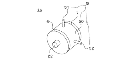
- 1 is a perspective view showing a motor according to Embodiment 1
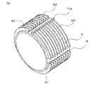
- FIG. FIG. 2 is a perspective view showing part of the motor according to the first embodiment
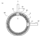
- FIG. 2 is a cross-sectional view showing the motor according to the first embodiment
- FIG. 2 is a cross-sectional view showing part of the motor according to the first embodiment
- FIG. FIG. 5 is a sectional view showing part of another motor according to the second embodiment; Sectional drawing which shows the motor concerning Embodiment 3.
- FIG. 11 is a cross-sectional view showing a motor according to a fifth embodiment; Sectional drawing which shows some motors concerning Embodiment 5.
- FIG. 11 is a cross-sectional view showing a motor according to a seventh embodiment; Sectional drawing which shows some motors concerning Embodiment 7.
- FIG. 11 is a cross-sectional view showing part of another motor according to the seventh embodiment;
- FIG. 12 is a cross-sectional view showing part of a motor according to an eighth embodiment;
- FIG. 12 is a cross-sectional view showing part of another motor according to the eighth embodiment;
- FIG. 12 is a perspective view showing a motor device according to a ninth embodiment;
- FIG. 14 is a diagram showing the operation of the motor device according to the ninth embodiment;
- FIG. 1 is a sectional view showing the motor 1a according to the first embodiment
- FIG. 2 is a perspective view showing the motor 1a according to the first embodiment.
- the motor 1 a includes a rotor 2 , a stator 3 , an inner frame 4 and an outer frame 5 .
- the motor 1a further includes a load-side bracket 6 having a load-side bearing 60 and an anti-load-side bracket 7 having an anti-load-side bearing 70 . Details will be described below.
- the rotor 2 is cylindrical.
- the rotor 2 has a rotor core 20 , magnets 21 and a shaft 22 .
- the shaft 22 is arranged through the rotor core 20 , the load-side bracket 6 , the anti-load-side bracket 7 , the load-side bearing 60 , and the anti-load-side bearing 70 . Further, the shaft 22 is rotatably supported by the load side bracket 6 and the anti-load side bracket 7 via the load side bearing 60 and the anti-load side bearing 70, respectively.
- the direction in which the shaft 22 extends will be referred to as the axial direction of the motor 1a.
- the axial direction of the motor 1a coincides with the axial directions of the inner frame 4 and the outer frame 5, which will be described later.
- the stator 3 is cylindrical.
- a cylindrical stator 3 is arranged to surround the rotor 2 .
- the stator 3 has a stator core 30 and stator coils 31 .
- the rotor 2 and stator 3 are concentric.
- the inner frame 4 is tubular.
- a stator 3 is arranged inside the cylindrical inner frame 4 .
- the stator 3 and inner frame 4 are concentric.
- the outer frame 5 (described later) side is referred to as the outer peripheral side of the inner frame 4
- the shaft 22 side is referred to as the inner peripheral side of the inner frame 4 .
- the outer frame 5 has a cylindrical side wall portion 50 . Between the inlet nipple 51 of the inlet header flow path 40 and the second flow path, the side wall portion 50 of the outer frame 5 has a resistance portion, which is a second flow-path-side resistance portion, which acts as a resistance to the circulation of the cooling liquid. 10a is formed. A detailed description of the resistor portion 10a will be given later.
- the outer frame 5 further has an inlet nipple 51, which is an inlet for cooling liquid, and an outlet nipple 52, which is an outlet for cooling liquid, which are formed on the side wall portion 50.
- the outlet nipple 52 is formed on the side wall portion 50 circumferentially spaced from the inlet nipple 51 .
- the present disclosure shows an example in which the inlet nipple 51 and the outlet nipple 52 are formed at positions separated by 90° in the circumferential direction, the arrangement of the inlet nipple 51 and the outlet nipple 52 is not limited to this.
- the inner frame 4 is arranged inside the cylindrical side wall portion 50 . That is, the outer frame 5 is arranged on the outer peripheral side of the inner frame 4 .
- the side walls 50 of the inner frame 4 and the outer frame 5 are concentric.
- a load-side bracket 6 is installed at one end of the side wall portion 50 of the inner frame 4 and the outer frame 5, and an anti-load-side bracket 7 is installed at the other end.
- FIG. 3 is a perspective view showing part of the motor 1a according to the first embodiment.
- the side wall portion 50 of the outer frame 5, the inlet nipple 51 and the outlet nipple 52 are omitted, but the resistance portion 10a formed on the side wall portion 50 of the outer frame 5 is shown.
- the side wall portion 50 of the outer frame 5, the load-side bracket 6, and the anti-load-side bracket 7, a flow path ( described later) are formed.
- the inner frame 4 is formed with an inlet header channel 40 and an outlet header channel 41 .
- the inlet header channel 40 and the outlet header channel 41 are channels extending in the axial direction of the motor 1a.
- the inlet nipple 51 is formed in communication with the inlet header channel 40 .
- the inlet nipple 51 is arranged opposite the inlet header channel 40 .
- the outlet nipple 52 is formed in communication with the outlet header channel 41 .
- the outlet nipple 52 is arranged opposite the outlet header channel 41 .
- the cooling liquid flows into the inlet header channel 40 from the outside of the motor 1a through the inlet nipple 51.
- the inlet nipple 51 and the outlet nipple 52 are formed on the side wall portion 50 at circumferentially separated positions. Divided into a clockwise direction and a clockwise direction, it circulates along the outer circumference of the inner frame 4 .
- the cooling liquid separated into the counterclockwise direction and the clockwise direction respectively flows into the outlet header channel 41 and joins.
- the coolant that joins in the outlet header channel 41 flows out from the outlet nipple 52 to the outside of the motor 1a.
- the flow path through which the coolant flows counterclockwise is referred to as the first flow path.
- One end of the first channel is connected to the inlet header channel 40 and the other end is connected to the outlet header channel 41 .
- a flow path through which the coolant flows clockwise when viewed from the load-side bracket 6 side shown in FIG. 2 is referred to as a second flow path.
- the second flow path has one end connected to the inlet nipple 51 and the other end connected to the outlet nipple 52 .
- a groove portion 8 which is a first groove portion, is formed on the outer peripheral side of the inner frame 4 toward the inner peripheral side.
- the groove portion 8 is formed integrally with the inner frame 4 by cutting the inner frame 4, for example.
- the formation of the groove portion 8 is not limited to cutting the inner frame 4, and may be formed by casting or the like.
- the groove portion 8 is formed along the outer circumference of the inner frame 4 . A coolant flows through the groove portion 8 .
- a heat radiation fin 80 that is a first heat radiation fin is provided between the grooves 8 .
- the heat radiation fins 80 are formed along the outer periphery of the inner frame 4 . That is, the heat radiation fins 80 extend in the circumferential direction of the inner frame 4 .
- An end portion of the heat radiation fin 80 on the outer frame 5 side is in contact with the side wall portion 50 of the outer frame 5 .
- first passages the passages formed by being surrounded by the inner frame 4, the heat radiating fins 80, and the side wall portion 50 of the outer frame 5 are referred to as first passages.
- the passages through which the cooling liquid flows counterclockwise that is, the passages formed by being surrounded by the inner frame 4, the heat radiation fins 80, and the side wall portion 50 of the outer frame 5 are combined to form a first flow.
- it is written as a road.
- a groove portion 9, which is a second groove portion, is formed on the outer peripheral side of the inner frame 4 toward the inner peripheral side.
- the channel length of the second channel it refers to the channel length of the groove portion 9 .
- the inlet nipple 51 and the outlet nipple 52 are formed on the side wall portion 50 at positions separated by 90° in the circumferential direction.
- the channel length is different.
- the channel length of the second channel is shorter than the channel length of the first channel.
- the groove portion 9 is formed integrally with the inner frame 4 by cutting the inner frame 4, for example.
- the formation of the groove portion 9 is not limited to cutting the inner frame 4, and may be formed by casting or the like.
- the groove portion 9 is formed along the outer circumference of the inner frame 4 . A coolant flows through the groove portion 9 .
- a heat radiation fin 90 that is a second heat radiation fin is provided between the grooves 9 .
- the heat radiation fins 90 are formed along the outer periphery of the inner frame 4 . That is, the heat radiation fins 90 extend in the circumferential direction of the inner frame 4 .
- An end portion of the heat radiation fin 90 on the outer frame 5 side is in contact with the side wall portion 50 of the outer frame 5 .
- the passages formed by being surrounded by the inner frame 4, the heat radiating fins 90, and the side wall portion 50 of the outer frame 5 are referred to as second passages.
- the passages through which the cooling liquid flows clockwise that is, the passages formed by being surrounded by the inner frame 4, the heat radiating fins 90, and the side wall portion 50 of the outer frame 5 are combined to form a second passage.
- the number of grooves 8 and grooves 9 of the motor 1a is the same.
- the depths of the grooves 8 and 9 on the shaft 22 side and the widths of the grooves 8 and 9 on the axial side are the same.
- the axial widths of the radiation fins 80 and 90 are the same. That is, the cross-sectional shapes of the first flow path and the second flow path in the direction perpendicular to the axial direction of the motor 1a are the same.
- “equivalent” shall include equivalent and substantially equivalent.
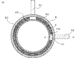
- FIG. 4 is a sectional view showing the motor 1a according to the first embodiment
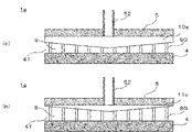
- FIG. 5 is a sectional view showing a part of the motor 1a according to the first embodiment.
- FIG. 4 is a sectional view of a plane perpendicular to the axial direction of the motor 1a.
- FIG. 5 is a sectional view showing the AA section of the motor 1a shown in FIG.
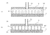
- FIG. 5(a) is a cross-sectional view of the second flow path side viewed from the AA cross section of the motor 1a shown in FIG. 4, and
- FIG. 1 is a cross-sectional view of the channel side of No. 1.
- FIG. 1 is a cross-sectional view of the channel side of No. 1.
- the side wall portion 50 of the outer frame 5 has a resistance portion between the inlet nipple 51 of the inlet header flow channel 40 and the second flow channel, which acts as a resistance to the circulation of the cooling liquid.
- 10a is formed.
- the resistance portion 10 a has a convex shape protruding from the side wall portion 50 of the outer frame 5 toward the inner frame 4 .
- the resistance portion 10 a has a gap between the inner frame 4 side end portion and the inner frame 4 .
- the coolant that has flowed into the inlet header channel 40 through the inlet nipple 51 passes through the gap between the inner frame 4 side end of the resistance portion 10a and the inner frame 4, and flows into the second channel. . Due to the resistance portion 10a, the pressure loss in the channel from the inlet nipple 51 to the inlet of the second channel becomes greater than the pressure loss in the channel from the inlet nipple 51 to the inlet of the first channel.
- the cross-sectional shapes of the first flow path and the second flow path are assumed to be the same.
- the pressure loss in the first flow path is greater than that in the second flow path, Coolant flow rate is reduced.
- the cooling performance is degraded, the temperature of the stator coil 31 is increased, the temperature of the entire motor is increased, and the efficiency of the motor is decreased.
- the resistance portion 10a formed in the motor 1a reduces the pressure loss in the channel from the inlet nipple 51 to the inlet of the second channel to the pressure in the channel from the inlet nipple 51 to the inlet of the first channel. It is the one that makes it bigger than the loss. As a result, the difference in pressure loss between the first flow path and the second flow path can be reduced, so the difference in flow rate between the cooling liquid flowing through the first flow path and the flow rate flowing through the second flow path can be reduced. .
- the motor 1a has the stator 3 surrounding the rotor 2 arranged inside, and the inlet header channel 40, the outlet header channel 41, the first channel and the second channel through which the coolant flows. is formed, a cylindrical side wall portion 50 surrounding the outer periphery of the inner frame 4, an inlet nipple 51 formed in communication with the inlet header channel 40 and through which the coolant flows, and an outlet an outer frame 5 having an outlet nipple 52 formed in communication with the header channel 41 and through which coolant flows out, the first channel and the second channel each having one end at the inlet header channel 40; and the other end is connected to the outlet header channel 41, and the cross-sectional shapes of the first channel and the second channel are the same, and the second channel is provided on the inner frame 4 for cooling.
- the liquid flows in the direction opposite to the first flow path, the length of the circumferential direction through which the cooling liquid flows is shorter than that of the first flow path, and the inlet nipple 51 of the inlet header flow path 40 and the second flow path A resistance portion 10a is formed between them to resist the circulation of the cooling liquid.
- the motor 1a can reduce the temperature difference in the circumferential direction of the stator coils 31 arranged inside the inner frame 4, efficiently cool the stator coils 31, and cool the motor 1a. can improve efficiency.
- how much the heat of the stator coil 31 is transferred to the cooling liquid via the first and second flow paths depends on the heat transfer coefficient of the flow paths and the surface area of the flow paths in contact with the cooling liquid. and the difference between the temperature of the channel and the temperature of the coolant.
- the result of multiplying the heat transfer coefficient of the channel by the surface area of the channel in contact with the coolant and the average value of the difference between the temperature of the channel and the temperature of the coolant in the circumferential direction is the first channel and the By designing the cross-sectional area of the flow path so that the ratio of the flow path lengths in the second flow path is approximately the same as the ratio of the respective flow path lengths and the difference between the temperature of the flow path and the temperature of the cooling liquid is small, the motor 1a can further improve the cooling efficiency.
- the flow path length of the first flow path is longer than the flow path length of the second flow path. It moves more to the coolant flowing through the first channel than to the liquid. Therefore, the temperature of the coolant increases near the outlet nipple 52 .
- the motor 1a If the motor 1a is designed as described above, the motor 1a will have an increased pressure loss in the second flow path and a reduced flow rate of the coolant flowing through the second flow path. As a result, in the motor 1a, the flow rate of the cooling liquid flowing through the first flow path increases, and the temperature of the cooling liquid also decreases near the outlet nipple 52, so that the temperature unevenness of the cooling liquid can be reduced, and the cooling efficiency can be improved. can improve.
- the resistance portion 10a extends from one end side to the other end side of the side wall portion 50 of the outer frame 5 . This makes it easier to manufacture the resistance portion 10a during extrusion molding, and the effects of the present disclosure can be obtained more, but the length of the resistance portion 10a is not limited to this.
- the resistance portion 10a may be formed in the central portion of the side wall portion 50 of the outer frame 5 near the inlet nipple 51 in the motor 1a where the coolant flows more easily. As a result, the motor 1a can reduce the difference in flow rate of the coolant in the axial direction of the motor 1a.
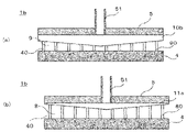
- FIG. 6 is a sectional view showing a motor 1b according to the second embodiment
- FIG. 7 is a sectional view showing a part of the motor 1b according to the second embodiment.
- FIG. 6 is a sectional view of a plane perpendicular to the axial direction of the motor 1b.
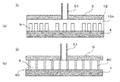
- FIG. 7 is a sectional view showing a BB section of the motor 1b shown in FIG. 7A is a cross-sectional view of the second flow path side viewed from the BB cross section of the motor 1b shown in FIG. 6, and
- FIG. 1 is a cross-sectional view of the channel side of No. 1.
- FIG. 6 and 7 the components denoted by the same reference numerals as those in FIGS.
- a resistance portion 10b which is a second flow path side resistance portion, is formed between an inlet nipple 51 of the inlet header flow path 40 and the second flow path. and the first flow path, in that a resistance portion 11a, which is a first flow path side resistance portion, is formed. Details will be described below.
- the side wall portion 50 of the outer frame 5 has a flow resistance of the cooling liquid between the inlet nipple 51 of the inlet header flow path 40 and the second flow path. is formed.
- the resistance portion 10 b has a convex shape protruding from the side wall portion 50 of the outer frame 5 toward the inner frame 4 .
- the resistance portion 10 b has a gap between the inner frame 4 side end portion and the inner frame 4 .
- the length of the resistance portion 10b from the side wall portion 50 of the outer frame 5 to the end on the inner frame 4 side, that is, the height of the resistance portion 10b is the side wall of the outer frame 5 near the inlet nipple 51 in the axial direction of the motor 1b.
- the central portion of the portion 50 is high, and the end portion side of the side wall portion 50 of the outer frame 5 far from the inlet nipple 51 is low.
- the closer the resistance portion 10 b is to the inlet nipple 51 the greater the resistance to circulation of the coolant, and the farther away from the entrance nipple 51 , the smaller the resistance to circulation of the coolant.
- the coolant flows between the inlet nipple 51 of the inlet header channel 40 and the first channel.
- the resistance portion 11 a has a convex shape protruding from the side wall portion 50 of the outer frame 5 toward the inner frame 4 .
- the resistance portion 11 a has a gap between the inner frame 4 side end portion and the inner frame 4 .
- the length of the resistance portion 11a from the side wall portion 50 of the outer frame 5 to the end on the inner frame 4 side, that is, the height of the resistance portion 11a is the side wall of the outer frame 5 near the inlet nipple 51 in the axial direction of the motor 1b.
- the central portion of the portion 50 is high, and the end portion side of the side wall portion 50 of the outer frame 5 far from the inlet nipple 51 is low.
- the closer the resistance portion 11 a is to the inlet nipple 51 the greater the resistance to circulation of the coolant, and the farther from the entrance nipple 51 , the smaller the resistance to circulation of the coolant.
- the height of the resistance portion 10b is higher than the height of the resistance portion 11a.
- the pressure loss in the channel from the inlet nipple 51 to the inlet of the second channel is greater than the pressure loss in the channel from the inlet nipple 51 to the inlet of the first channel.
- the resistance to the flow of the coolant by the resistance portion 10b is greater than the resistance to the flow of the coolant by the resistance portion 11a.
- the difference in pressure loss between the first flow path and the second flow path can be reduced by the resistance portion 10b. It is possible to reduce the difference in flow rate flowing through the flow path. As a result, the motor 1b can reduce the temperature difference in the circumferential direction of the stator coil 31 arranged inside the inner frame 4, efficiently cool the stator coil 31, and increase the efficiency of the motor 1b. can improve.
- the pressure loss in the second flow path increases, and the flow rate of the coolant flowing through the second flow path decreases.
- the flow rate of the cooling liquid flowing through the first flow path increases, and the temperature of the cooling liquid also decreases in the vicinity of the outlet nipple 52, so that the temperature unevenness of the cooling liquid can be reduced, and the cooling efficiency is improved. can improve.
- the pressure loss in the channel from the nipple 51 to the inlet of the first channel is the pressure loss in the channel far from the inlet nipple 51 to the inlet of the second channel from the inlet nipple 51 and the pressure loss from the inlet nipple 51 to the inlet of the second channel. It can be made larger than the pressure loss in the channel up to the inlet of the first channel.
- the difference in the axial flow rate of the coolant flowing through the first flow path and the second flow path can be reduced, so that the temperature unevenness in the axial direction of the stator coil 31 can be reduced.
- the stator coil 31 can be cooled more efficiently, and the efficiency of the motor 1b can be improved.
- the inlet nipples 51 are respectively arranged in the central portions of the side wall portions 50 of the outer frame 5.
- the motor 1b can reduce the difference in flow rate of the coolant in the axial direction of the motor 1b.
- FIG. 8 shows a motor 1c in which an inlet nipple 51 is arranged on one end side of the side wall portion 50 of the outer frame 5 in the axial direction.
- FIG. 8 is a sectional view showing part of another motor 1c according to the second embodiment.
- FIG. 8 is a sectional view corresponding to the BB section of the motor 1b shown in FIG. 8(a) is a cross-sectional view of the second channel side viewed from the BB cross section shown in FIG. 6, and
- FIG. 8(b) is a cross-sectional view of the first channel side viewed from the BB cross section shown in FIG. is a cross-sectional view.
- the motor 1c differs from the motor 1b in that the inlet nipple 51 is arranged at one axial end of the motor 1c. Details will be described below.
- the resistance portion 10c which is the second flow path side resistance portion, has a height of the side wall portion 50 of the outer frame 5 near the inlet nipple 51 in the axial direction of the motor 1c. It is high on one end side and low on the other end side of the side wall portion 50 of the outer frame 5 far from the inlet nipple 51 .
- the height of the resistance portion 11b which is the first flow path side resistance portion, is high at one end side of the side wall portion 50 of the outer frame 5 near the inlet nipple 51 in the axial direction of the motor 1c, and The other end side of the side wall portion 50 of the outer frame 5 far from the nipple 51 is lowered.
- the height of the resistance portion 10c is higher than the height of the resistance portion 11b.
- the motor 1c can reduce the difference in flow rate of the coolant in the axial direction of the motor 1c.
- FIG. 9 is a sectional view showing a motor 1d according to the third embodiment
- FIG. 10 is a sectional view showing a part of the motor 1d according to the third embodiment.
- FIG. 9 is a sectional view of a plane perpendicular to the axial direction of the motor 1d.
- FIG. 10 is a sectional view showing the CC section of the motor 1d shown in FIG. 10(a) is a cross-sectional view of the second flow path side viewed from the CC cross-section of the motor 1d shown in FIG. 9, and
- FIG. 10(b) is a cross-sectional view of the motor 1d shown in FIG. 1 is a cross-sectional view of the channel side of No. 1.
- the motor 1d differs from the motor 1a in that a resistance portion 10d, which is a second flow path side resistance portion, is formed between the outlet nipple 52 of the outlet header flow path and the second flow path. Details will be described below.
- the side wall portion 50 of the outer frame 5 has an outlet nipple 52 of the outlet header flow path and the second flow path, which acts as a flow resistance for the cooling liquid.
- a resistance portion 10d is formed.
- the resistance portion 10 d has a convex shape protruding from the side wall portion 50 of the outer frame 5 toward the inner frame 4 .
- the resistance portion 10 d has a gap between the inner frame 4 side end portion and the inner frame 4 .
- the coolant that has flowed through the second flow path passes through the gap between the inner frame 4 side end of the resistance portion 10d and the inner frame 4, and flows through the first flow path and the outlet header flow. Merge on Road 41.
- the pressure loss in the flow path flowing from the outlet of the second flow path to the outlet nipple 52 is greater than the pressure loss in the flow path flowing from the outlet of the first flow path to the outlet nipple 52 due to the resistance portion 10d. will also grow.
- the difference in pressure loss between the first flow path and the second flow path can be reduced by the resistance portion 10d. It is possible to reduce the difference in flow rate flowing through the flow path. As a result, the motor 1d can reduce the temperature difference in the circumferential direction of the stator coil 31 arranged inside the inner frame 4, efficiently cool the stator coil 31, and increase the efficiency of the motor 1d. can improve.
- the pressure loss in the second flow path increases and the flow rate of the cooling liquid flowing through the second flow path decreases, so that the motor 1d increases the flow rate of the cooling liquid flowing through the first flow path.
- the temperature of the cooling liquid also becomes low near the outlet nipple 52, the temperature unevenness of the cooling liquid can be reduced, and the cooling efficiency can be further improved.
- FIG. 11 is a sectional view showing part of the motor 1e according to the fourth embodiment.
- FIG. 11 is a sectional view corresponding to the CC section of the motor 1d shown in FIG. 11(a) is a cross-sectional view of the outlet header channel 41 as viewed from the second channel side
- FIG. 11(b) is a cross-sectional view of the first channel from the outlet header channel 41.
- FIG. . the components denoted by the same reference numerals as those in FIG. 10 are the same as or correspond to those of the motor 1d, and detailed description thereof will be omitted.
- a resistance portion 10e as a second flow path side resistance portion is formed between the outlet nipple 52 of the outlet header flow path 41 and the second flow path, and the outlet nipple of the outlet header flow path 41 is formed. It is different from the motor 1d in that a resistance portion 11c, which is a first flow path side resistance portion, is formed between 52 and the first flow path. Details will be described below.
- the side wall portion 50 of the outer frame 5 has a resistance portion between the outlet nipple 52 of the outlet header flow path 41 and the second flow path, which acts as a resistance to the circulation of the cooling liquid. 10e is formed.
- the resistance portion 10 e has a convex shape protruding from the side wall portion 50 of the outer frame 5 toward the inner frame 4 .
- the resistance portion 10 e has a gap between the inner frame 4 side end portion and the inner frame 4 .
- the height of the resistance portion 10e is high at the central portion of the side wall portion 50 of the outer frame 5 near the outlet nipple 52 in the axial direction of the motor 1e, and low at the end portion side of the side wall portion 50 of the outer frame 5 far from the outlet nipple 52.
- the closer the resistance portion 10 e is to the outlet nipple 52 the greater the resistance to circulation of the coolant, and the farther from the outlet nipple 52 , the smaller the resistance to circulation of the coolant.
- a resistance portion 11c is formed in the side wall portion 50 of the outer frame 5, there is a resistance to the circulation of the cooling liquid between the outlet nipple 52 of the outlet header channel and the first channel.
- a resistance portion 11c is formed in the side wall portion 50 of the outer frame 5 toward the inner frame 4 .
- the resistance portion 11 c has a gap between the inner frame 4 side end portion and the inner frame 4 .
- the height of the resistance portion 11c is high at the central portion of the side wall portion 50 of the outer frame 5 near the outlet nipple 52 in the axial direction of the motor 1e, and low at the end portion side of the side wall portion 50 of the outer frame 5 far from the outlet nipple 52.
- the height of the resistance portion 10e is higher than the height of the resistance portion 11c.
- the closer the resistance portion 11 c is to the outlet nipple 52 the greater the resistance to circulation of the coolant, and the farther from the outlet nipple 52 , the smaller the resistance to circulation of the coolant.
- the resistance to circulation of the coolant by the resistance portion 11c is greater than the resistance to circulation of the coolant by the resistance portion 11c.
- the difference in pressure loss between the first flow path and the second flow path can be reduced by the resistance portion 10e. It is possible to reduce the difference in flow rate flowing through the flow path. As a result, the motor 1e can reduce the temperature difference in the circumferential direction of the stator coil 31 disposed inside the inner frame 4, efficiently cool the stator coil 31, and increase the efficiency of the motor 1e. can improve.
- the pressure loss in the second flow path increases, and the flow rate of the coolant flowing through the second flow path decreases.
- the flow rate of the cooling liquid flowing through the first flow path increases, and the temperature of the cooling liquid also decreases near the outlet nipple 52, so that the temperature unevenness of the cooling liquid can be reduced, and the cooling efficiency can be improved. can improve.
- the pressure loss and the pressure loss of the flow path flowing into the outlet nipple 52 from the outlet of the second flow path in the portion close to the outlet nipple 52 in the axial direction of the motor 1e are controlled by the resistance portion 10e and the resistance portion 11c.
- the pressure loss of the flow path flowing into the outlet nipple 52 from the outlet of the first flow path is the pressure loss of the flow path flowing into the outlet nipple 52 from the outlet of the second flow path far from the outlet nipple 52 and the pressure loss of the flow path flowing into the outlet nipple 52 from the outlet of the second flow path.
- the motor 1e can reduce the difference in flow rate in the axial direction of the coolant flowing through the first flow path and the second flow path. While being able to cool the stator coil 31 more efficiently, the efficiency of the motor 1e can be improved.
- the outlet nipple 52 is arranged at the center of the side wall portion 50 of the outer frame 5.
- the height of the resistance portion 10e and the resistance portion 11c may If the distance to the outlet nipple 52 in the axial direction of the motor 1e is higher, and the distance to the outlet nipple 52 is lower, the motor 1e can reduce the difference in flow rate of the coolant in the axial direction of the motor 1e.
- Embodiment 5 is a cross-sectional view showing a motor 1f according to the fifth embodiment
- FIG. 13 is a cross-sectional view showing a part of the motor 1f according to the fifth embodiment
- FIG. It is a sectional view showing a part of the motor 1f.
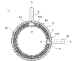
- FIG. 12 is a sectional view of a plane perpendicular to the axial direction of the motor 1f.
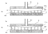
- FIG. 13 is a sectional view showing a DD section of the motor 1f shown in FIG. 13(a) is a cross-sectional view of the second flow path side viewed from the DD cross section of the motor 1f shown in FIG. 12, and
- FIG. 1 is a cross-sectional view of the channel side of No. 1.
- FIG. 14 is a sectional view showing the EE section of the motor 1f shown in FIG. 14(a) is a cross-sectional view of the second flow path side viewed from the EE cross section of the motor 1f shown in FIG. 12, and FIG. 1 is a cross-sectional view of the channel side of No. 1.
- FIG. 12 13 and 14, the same reference numerals as those in FIGS. 4 and 5 indicate the same or corresponding configurations as those of the motor 1a, so detailed description thereof will be omitted.
- a resistance portion 10a which is a second flow path side resistance portion, is formed between an inlet nipple 51 of the inlet header flow path 40 and the second flow path, and an outlet nipple of the outlet header flow path 41 is formed. It differs from the motor 1a in that a resistance portion 10d, which is a second flow path side resistance portion, is formed between 52 and the second flow path. Details will be described below.
- the motor 1f has a flow resistance of the cooling liquid between the inlet nipple 51 of the inlet header flow path 40 and the second flow path.
- a resistance portion 10a is formed between the outlet nipple 52 of the outlet header flow channel 41 and the second flow channel, and a resistance portion 10d that resists the circulation of the cooling liquid is formed.
- the pressure loss in the flow path from the inlet nipple 51 to the inlet of the second flow path is greater than the pressure loss in the flow path from the inlet nipple 51 to the inlet of the first flow path due to the resistance portion 10a.
- the pressure loss in the flow path from the outlet of the second flow path to the outlet nipple 52 is greater than the pressure loss in the flow path from the outlet of the first flow path to the outlet nipple 52.
- the difference in pressure loss between the first flow path and the second flow path can be reduced by the resistance portion 10a and the resistance portion 10d.
- the difference in flow rate flowing through the second flow path can be reduced.
- the motor 1f can reduce the temperature difference in the circumferential direction of the stator coil 31 arranged inside the inner frame 4, efficiently cool the stator coil 31, and increase the efficiency of the motor 1f. can improve.
- the resistance portion 10a and the resistance portion 10d increase the pressure loss in the second flow path and decrease the flow rate of the coolant flowing through the second flow path.
- the flow rate of the cooling liquid flowing through the first flow path increases, and the temperature of the cooling liquid also decreases near the outlet nipple 52, so that the temperature unevenness of the cooling liquid can be reduced, and the cooling efficiency is improved. can improve.
- Embodiment 6 are sectional views showing a part of the motor 1g according to the sixth embodiment, respectively.
- FIG. 15 is a sectional view corresponding to the DD section of the motor 1f shown in FIG. 16 is a sectional view corresponding to the EE section of the motor 1f shown in FIG.
- FIG. 15(a) is a cross-sectional view of the second channel side viewed from the inlet header channel 40
- FIG. 15(b) is a cross-sectional view of the first channel side viewed from the inlet header channel 40.
- It is a diagram. 16(a) is a cross-sectional view of the second flow channel side viewed from the outlet header flow channel 41
- 16(b) is a cross-sectional view of the first flow channel side from the outlet header flow channel 41. It is a diagram.
- a resistance portion 10b which is a second flow path side resistance portion, is formed between the inlet nipple 51 of the inlet header flow path 40 and the second flow path.
- a resistance portion 11a which is a first flow-path side resistance portion, is formed between the first flow path and the second flow path between the outlet nipple 52 of the outlet header flow path 41 and the second flow path. is formed, and a resistance portion 11c, which is a first flow path side resistance portion, is formed between the outlet nipple 52 and the first flow path. different. Details will be described below.
- the motor 1g has a resistance portion between the inlet nipple 51 of the inlet header flow path 40 and the second flow path, which acts as a resistance to the circulation of the cooling liquid.
- 10b is formed, and a resistance portion 10e is formed between the outlet nipple 52 of the outlet header channel 41 and the second channel.
- the height of the resistance portion 10b is high at the central portion of the side wall portion 50 of the outer frame 5 near the inlet nipple 51 in the axial direction of the motor 1g, and is low at the end portion side of the side wall portion 50 of the outer frame 5 far from the inlet nipple 51.
- the height of the resistance portion 10e is high at the central portion of the side wall portion 50 of the outer frame 5 near the outlet nipple 52 in the axial direction of the motor 1g, and is high at the side wall portion of the outer frame 5 far from the outlet nipple 52. It becomes lower on the end side of 50 .
- the side wall portion 50 of the outer frame 5 has an inlet nipple 51 of the inlet header channel 40 and the first channel.
- a resistance portion 11a is formed therebetween, and a resistance portion 11c is formed between the outlet nipple 52 of the outlet header flow path 41 and the first flow path.
- the height of the resistance portion 11a is high at the central portion of the side wall portion 50 of the outer frame 5 near the inlet nipple 51 in the axial direction of the motor 1g, and low at the end portion side of the side wall portion 50 of the outer frame 5 far from the inlet nipple 51.
- the height of the resistance portion 11c is high at the central portion of the side wall portion 50 of the outer frame 5 near the outlet nipple 52 in the axial direction of the motor 1g, and is high at the side wall portion of the outer frame 5 far from the inlet nipple 51. It becomes lower on the end side of 50 .
- the height of the resistance portion 10b is higher than the height of the resistance portion 11a, and the height of the resistance portion 10e is higher than the height of the resistance portion 11c.
- the difference in pressure loss between the first flow path and the second flow path can be reduced by the resistance portion 10b and the resistance portion 10e.
- the difference in flow rate flowing through the second flow path can be reduced.
- the motor 1g can reduce the temperature difference in the circumferential direction of the stator coil 31 arranged inside the inner frame 4, efficiently cool the stator coil 31, and increase the efficiency of the motor 1g. can improve.
- the pressure loss in the second flow path increases due to the resistance portion 10b and the resistance portion 10e, and the flow rate of the cooling liquid flowing through the second flow path decreases.
- the flow rate of the cooling liquid flowing through the first flow path increases, and the temperature of the cooling liquid also decreases near the outlet nipple 52, so that the temperature unevenness of the cooling liquid can be reduced, and the cooling efficiency can be improved. can improve.
- the pressure loss in the channel from the nipple 51 to the inlet of the first channel is the pressure loss in the channel far from the inlet nipple 51 to the inlet of the second channel from the inlet nipple 51 and the pressure loss from the inlet nipple 51 to the inlet of the second channel. It can be made larger than the pressure loss in the channel up to the inlet of the first channel.
- the pressure loss and the pressure loss of the flow path flowing into the outlet nipple 52 from the outlet of the second flow path in the portion close to the outlet nipple 52 in the axial direction of the motor 1g are controlled by the resistance portion 10e and the resistance portion 11c.
- the pressure loss of the flow path flowing into the outlet nipple 52 from the outlet of the first flow path is the pressure loss of the flow path flowing into the outlet nipple 52 from the outlet of the second flow path far from the outlet nipple 52 and the pressure loss of the flow path flowing into the outlet nipple 52 from the outlet of the second flow path.
- the motor 1g can reduce the difference in flow rate in the axial direction of the coolant flowing through the first flow path and the second flow path. , the stator coil 31 can be cooled more efficiently, and the efficiency of the motor 1g can be improved.
- Embodiment 6 an example in which the inlet nipple 51 and the outlet nipple 52 are arranged in the central portion of the side wall portion 50 of the outer frame 5 is shown, but the inlet nipple 51 and the outlet nipple 52 are arranged in the outer Regardless of which part of the side wall portion 50 of the frame 5 is arranged, the heights of the resistance portion 10b, the resistance portion 11a, the resistance portion 10e, and the resistance portion 11c are set close to the outlet nipple 52 in the axial direction of the motor 1g. By setting the distance higher and the distance lower, the motor 1g can reduce the difference in flow rate of the coolant in the axial direction of the motor 1g.
- FIG. 17 is a sectional view showing a motor 1h according to the seventh embodiment
- FIG. 18 is a sectional view showing a part of the motor 1h according to the seventh embodiment.
- FIG. 17 is a sectional view of a plane perpendicular to the axial direction of the motor 1h.
- FIG. 18 is a sectional view showing the FF section of the motor 1h shown in FIG.
- FIG. 18(a) is a cross-sectional view of the second flow path side viewed from the FF cross section of the motor 1h shown in FIG. 17, and
- FIG. 1 is a cross-sectional view of the channel side of No. 1.
- FIG. 17 and 18 the components denoted by the same reference numerals as those in FIGS.
- the motor 1h differs from the motor 1a in that a resistance portion 10f, which is a second flow path side resistance portion, is formed between the inlet nipple 51 of the inlet header flow path 40 and the second flow path.
- the radiation fin 90 is abbreviate
- the side wall portion 50 of the outer frame 5 has a resistance portion between the inlet nipple 51 of the inlet header flow channel 40 and the second flow channel, which acts as a resistance to the circulation of the cooling liquid. 10f is formed.
- the resistance portion 10f has an opening penetrating from the first channel side to the second channel side.
- the opening is a slit 12 recessed from the side of the inner frame 4 toward the side wall portion 50 of the outer frame 5.
- the slit 12 may be recessed from the outer frame 5 side to the inner frame 4 side, or may be formed between the outer frame 5 side end of the resistance portion 10f and the inner frame 4 side end, for example, the resistance portion 10f. may be provided in the central portion of the
- the coolant that has flowed into the inlet header channel 40 through the inlet nipple 51 passes through the slit 12 of the resistance portion 10f and flows into the second channel.
- the resistance portion 10f is formed to connect the inner frame 4 and the side wall portion 50 of the outer frame 5. Note that the resistance portion 10 f does not necessarily have to connect the inner frame 4 and the side wall portion 50 of the outer frame 5 . That is, the resistance portion 10f may have a gap between it and the side wall portion 50 side of the inner frame 4 or the outer frame 5 . In the motor 1h, for example, depressions are provided in the inner frame 4 and the side wall portions 50 of the outer frame 5, respectively, and the resistance portions 10f are inserted into the depressions. 10f may be placed.
- the difference in pressure loss between the first flow path and the second flow path can be reduced by the resistance portion 10f. It is possible to reduce the difference in flow rate flowing through the flow path.
- the motor 1h can reduce the temperature difference in the circumferential direction of the stator coil 31 arranged inside the inner frame 4, efficiently cool the stator coil 31, and improve the efficiency of the motor 1h. can improve.
- the resistance portion 10f increases the pressure loss in the second flow path and decreases the flow rate of the coolant flowing through the second flow path.
- the flow rate of the cooling liquid flowing through the first flow path increases, and the temperature of the cooling liquid also decreases in the vicinity of the outlet nipple 52, so that the temperature unevenness of the cooling liquid can be reduced, and the cooling efficiency is improved. can improve.
- FIG. 19 is a sectional view showing part of another motor 1i according to the seventh embodiment.
- FIG. 19 is a sectional view corresponding to the FF section of the motor 1h shown in FIG. 19(a) is a cross-sectional view of the second flow channel side viewed from the FF cross section shown in FIG. 17, and
- FIG. 19(b) is a cross-sectional view of the first flow channel side viewed from the FF cross section shown in FIG. is a cross-sectional view.
- FIG. 19 is a sectional view corresponding to the FF section of the motor 1h shown in FIG. 19(a) is a cross-sectional view of the second flow channel side viewed from the FF cross section shown in FIG. 17, and
- FIG. 19(b) is a cross-sectional view of the first flow channel side viewed from the FF cross section shown in FIG. is a cross-sectional view.
- the motor 1i differs from the motor 1h in that the openings of the resistance portion 10g, which is the second flow path side resistance portion, are hole portions 13. As shown in FIG. In addition, the radiation fin 90 is abbreviate
- the side wall portion 50 of the outer frame 5 has a resistance portion between the inlet nipple 51 of the inlet header flow path 40 and the second flow path, which acts as a resistance to the circulation of the cooling liquid.
- 10 g are formed.
- the resistance portion 10g has an opening penetrating from the first channel side to the second channel side. In the motor 1i, the opening is the hole 13.
- the resistance portion 10g may be a punching metal obtained by punching holes in a plate of metal or the like with a die of a punching press and processing the plate, for example.
- the coolant that has flowed into the inlet header channel 40 through the inlet nipple 51 passes through the hole 13 of the resistance portion 10g and flows into the second channel.
- the motor 1i can obtain the same effects as the motor 1h.
- the resistance portion 10f or the resistance portion 10g is formed between the inlet nipple 51 of the inlet header flow path 40 and the second flow path.
- a resistance portion 10f or a resistance portion 10g may be formed between the outlet nipple 52 and the second flow path of the inlet header flow path 40, between the inlet nipple 51 of the inlet header flow path 40 and the second flow path, and
- a resistor portion 10f or a resistor portion 10g may be formed both between the outlet nipple 52 of the outlet header channel 41 and the second channel.
- Embodiment 7 an example in which the openings are the slits 12 or the holes 13 is shown, but a net-like resistance portion may be arranged.
- FIG. 20 is a sectional view showing part of the motor 1j according to the eighth embodiment.
- FIG. 20 is a sectional view corresponding to the FF section of the motor 1h shown in FIG. 20(a) is a cross-sectional view of the second channel side viewed from the FF cross section shown in FIG. 17, and
- FIG. 20(b) is a cross-sectional view of the first channel side viewed from the FF cross section shown in FIG. is a cross-sectional view.
- the components denoted by the same reference numerals as in FIG. 18 are the same as or correspond to those of the motor 1h, so detailed description thereof will be omitted.
- the degree of opening of the opening of the resistance portion 10h which is the second flow path side resistance portion, is smaller in the axial direction of the outer frame 5 as it is closer to the inlet nipple 51, and is larger as it is farther from the inlet nipple 51.
- the radiation fin 90 is abbreviate
- the side wall portion 50 of the outer frame 5 has a resistance portion between the inlet nipple 51 of the inlet header flow path 40 and the second flow path, which acts as a resistance to the circulation of the cooling liquid. 10h is formed.
- the resistance portion 10f has an opening penetrating from the first channel side to the second channel side. In the motor 1j, the opening is a slit 12 recessed from the side of the inner frame 4 toward the side wall portion 50 of the outer frame 5.
- the coolant that has flowed into the inlet header channel 40 through the inlet nipple 51 passes through the slit 12 of the resistance portion 10h and flows into the second channel.
- the opening degree of the slit 12 is small at the central portion of the side wall portion 50 of the outer frame 5 near the inlet nipple 51 in the axial direction of the motor 1j, and the end of the side wall portion 50 of the outer frame 5 far from the inlet nipple 51. Large on the department side.
- the opening degree of the slits 12 in the motor 1j is determined by the number of the slits 12.
- the pressure loss in the passage from the inlet nipple 51 in the portion close to the inlet nipple 51 to the inlet of the second passage increases from the inlet nipple 51 in the portion far from the inlet nipple 51 to the inlet of the second passage. It becomes larger than the pressure loss of the channel to the inlet of the second channel.
- the opening degree of the slits 12 may be determined by the number of the slits 12 as in the motor 1j, or the width of the slits 12 in the axial direction or from the inner frame 4 side to the side wall portion 50 side of the outer frame 5. You can decide by the height of the recess.
- the difference in pressure loss between the first flow path and the second flow path can be reduced by the resistance portion 10h. It is possible to reduce the difference in flow rate flowing through the flow path.
- the motor 1j can reduce the temperature difference in the circumferential direction of the stator coil 31 arranged inside the inner frame 4, efficiently cool the stator coil 31, and increase the efficiency of the motor 1j. can improve.
- the pressure loss in the second flow path increases, and the flow rate of the coolant flowing through the second flow path decreases.
- the flow rate of the cooling liquid flowing through the first flow path increases, and the temperature of the cooling liquid also decreases in the vicinity of the outlet nipple 52, so that the temperature unevenness of the cooling liquid can be reduced, and the cooling efficiency can be improved. can improve.
- the pressure loss in the passage from the inlet nipple 51 to the inlet of the second passage in the portion close to the inlet nipple 51 in the axial direction of the motor 1j is reduced from the inlet nipple 51 by the resistance portion 10h. It can be made larger than the pressure loss in the flow path from the inlet nipple 51 to the inlet of the second flow path in the far portion. Therefore, the motor 1j can reduce the difference in the axial flow rate of the cooling liquid flowing through the second flow path, so that the temperature unevenness in the axial direction of the stator coil 31 can be reduced. Cooling can be performed efficiently, and the efficiency of the motor 1j can be improved.
- FIG. 21 is a sectional view showing part of another motor 1k according to the eighth embodiment.
- FIG. 21 is a sectional view corresponding to the FF section of the motor 1h shown in FIG. 21(a) is a cross-sectional view of the second flow channel side viewed from the FF cross section shown in FIG. 17, and
- FIG. 21(b) is a cross-sectional view of the first flow channel side viewed from the FF cross section shown in FIG. is a cross-sectional view.
- the degree of opening of the opening of the resistance portion 10i which is the second flow path side resistance portion, is smaller in the axial direction of the outer frame 5 as it is closer to the inlet nipple 51 and is larger as it is farther from the inlet nipple 51.
- the radiation fin 90 is abbreviate
- the side wall portion 50 of the outer frame 5 has a resistance portion between the inlet nipple 51 of the inlet header flow path 40 and the second flow path, which acts as a resistance to the circulation of the cooling liquid. 10i are formed.
- the resistance portion 10i has an opening penetrating from the first channel side to the second channel side. In the motor 1k, the opening is the hole 13.
- the coolant that has flowed into the inlet header channel 40 through the inlet nipple 51 passes through the hole 13 of the resistance portion 10g and flows into the second channel.
- the opening degree of the hole portion 13 is small at the center portion of the side wall portion 50 of the outer frame 5 near the inlet nipple 51 in the axial direction of the motor 1k, and is small at the center portion of the side wall portion 50 of the outer frame 5 far from the inlet nipple 51. It is large on the edge side.
- the opening degree of the holes 13 is determined by the number of the holes 13. As shown in FIG. As a result, in the axial direction of the motor 1k, the pressure loss in the channel from the inlet nipple 51 in the portion near the inlet nipple 51 to the inlet of the second channel is It becomes larger than the pressure loss of the channel to the inlet of the second channel.
- the degree of opening of the holes 13 may be determined by the number of the holes 13 as in the motor 1k or by the size of the holes 13 .
- the motor 1k can obtain the same effects as the motor 1j.
- the resistance portion 10h or the resistance portion 10i is formed between the inlet nipple 51 of the inlet header flow channel 40 and the second flow channel.
- the resistance portion 10h or the resistance portion 10i may be formed, between the inlet nipple 51 of the inlet header flow path 40 and the second flow path, and A resistor portion 10h or a resistor portion 10i may be formed both between the outlet nipple 52 of the outlet header channel 41 and the second channel.
- the side walls 50 of the outer frame 5 are provided between the inlet nipple 51 of the inlet header channel 40 and the first channel and between the outlet nipple 52 of the outlet header channel 41 and the first channel.
- a first flow-path-side resistance portion may be formed on at least one side between the flow path and the flow path to provide resistance to circulation of the cooling liquid.
- the first channel-side resistance portion has an opening penetrating from the first channel side to the second channel side.
- the degree of opening of the opening of the first channel-side resistance portion formed between the inlet nipple 51 of the inlet header channel 40 and the first channel is closer to the inlet nipple 51 in the axial direction of the outer frame 5. It is small, and the farther it is from the inlet nipple 51, the larger it is.
- the degree of opening of the opening of the first channel-side resistance portion formed between the outlet nipple 52 of the outlet header channel 41 and the first channel is The closer it is, the smaller it is, and the farther it is from the outlet nipple 52, the larger it is.
- the opening degree of the opening of the second flow path side resistance section is smaller than the opening degree of the opening of the first flow path side resistance section.
- the difference in the axial flow rate of the cooling liquid flowing through the first flow path can be reduced, so that the axial temperature unevenness of the stator coil 31 can be reduced. can be cooled more efficiently and the efficiency of the motor can be improved.
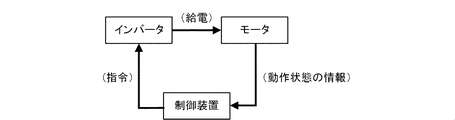
- Embodiment 9. 22 is a perspective view showing the motor device 100 according to the ninth embodiment, and FIG. 23 is a diagram showing the operation of the motor device 100 according to the ninth embodiment.
- the motor device 100 includes a motor 1, an inverter 101, and a control device (not shown in FIG. 22).
- Motor 1 refers to any one of motors 1a to 1k.
- the control device receives from the motor 1 information on the operating state of the motor 1, such as the rotation speed and torque of the rotor 2 of the motor 1, or the temperature of the motor 1. Based on this information, the controller determines the amplitude and phase of the current to be supplied to the motor 1 and sends commands to the inverter 101 .
- the inverter 101 is installed on the anti-load side bracket 7 of the motor 1 .
- the inverter 101 feeds the stator coil 31 of the motor 1 with current having amplitude and phase based on a command from the control device.
- the current having the amplitude and phase based on the command is supplied to the stator coil 31 of the motor 1, the rotor 2 rotates.
- power is transmitted to the outside of the motor 1 from the shaft 22 fixed to the center of the rotor 2 . In this way, inverter 101 controls the rotation speed and torque of rotor 2 of motor 1 .
- stator coil 31 copper loss occurs in the stator coil 31 due to the current flowing through the stator coil 31 .
- iron loss occurs in the electromagnetic steel sheets (not shown in FIG. 22) in which the stator core 30 and the rotor core 20 are laminated, and when the rotor 2 rotates, the load side bearing 60 and the anti-load side bearing 60 are generated. 70 and mechanical loss and other losses occur.
- the generated loss turns into heat and moves inside the motor 1 to raise the temperature of each part such as the stator coil 31 .
- the heat that has passed through each part is radiated mainly from the inner frame 4 to the cooling liquid flowing through the first flow path and the second flow path through heat transfer.
- the motor device 100 determines the amplitude and phase of the current to be supplied to the motor 1 from the motor 1, the inverter 101 that controls the rotation speed and torque of the motor 1, and information on the operating state of the motor 1. and a controller for sending the determined amplitude and phase of the current to the inverter 101 .
- the motor device 100 can cool the stator coil 31 more efficiently, so that the motor 1 can be efficiently cooled.
- the motor device 100 can increase the current that flows from the inverter 101 of the motor device 100 to the motor 1, so that the motor device 100 with a higher output, that is, a higher rotational speed and a higher torque can be obtained.
- the motor device 100 integrates the motor 1 and the inverter 101, wiring and parts are reduced, and the work of mounting the motor 1 on the equipment is facilitated, and workability can be improved.
- the motor device 100 is separate from the control device in the ninth embodiment, the motor 1, the inverter 101 and the control device may be integrated.
- the inverter 101 is arranged on the anti-load side bracket 7 side of the motor 1, that is, behind the motor 1.
- the number of grooves 8 and 9 formed in the inner frame 4 may be one. That is, the inner frame 4 does not have to have the heat radiation fins 80 and the heat radiation fins 90 .
- the first flow path is formed by being surrounded by the groove portion 8 , the side wall portion 50 of the outer frame 5 , the load side bracket 6 and the anti-load side bracket 7 .
- the second flow path is formed by being surrounded by the groove portion 9 , the side wall portion 50 of the outer frame 5 , the load-side bracket 6 , and the anti-load-side bracket 7 .
- the inner frame 4 has only one groove portion 8
- the first flow path, the inlet header flow path 40, and the outlet header flow path 41 need not be formed separately.
- the groove portion 9 when one groove portion 9 is formed in the inner frame 4, the second flow path, the inlet header flow path 40, and the outlet header flow path 41 do not have to be formed separately. good.
- the spatial region surrounded by the inner frame 4, the side wall portion 50 of the outer frame 5, the load-side bracket 6, and the anti-load-side bracket 7 is defined as the first flow channel and the second flow channel.
- both ends of the inner frame 4 in the axial direction did not have the radiating fins 80 and the radiating fins 90 .
- the space area surrounded by the inner frame 4 , the side wall portions 50 of the outer frame 5 , and the radiating fins 80 at both ends of the inner frame 4 in the axial direction may be used as the first flow path.
- a space area surrounded by the inner frame 4 , the side wall portions 50 of the outer frame 5 , and the heat radiation fins 90 at both ends of the inner frame 4 in the axial direction may be used as the second flow path.
- heat radiation fins may be provided along the entire circumference of both ends of the inner frame 4 in the axial direction.
- the resistor portions 10a to 10g hereinafter collectively referred to as the “resistor portion 10”
- the resistor portion 11a formed on the side wall portion 50 of the outer frame 5 are used. Since there is a possibility that the resistor portion 11c (hereinafter collectively referred to as “resistor portion 11”) may come into contact with the radiating fins, if notches or the like are provided at positions corresponding to the resistor portions 10 and 11 of the radiating fins, good.
- the periphery of the cutouts may be filled with resin or the like. As a result, leakage of coolant can be suppressed.
- inlet nipple 51 and the outlet nipple 52 are arranged on the side wall portion 50 of the outer frame 5 at the central portion or the end portion side has been shown, but they may be arranged anywhere on the side wall portion 50 . You may
- an O-ring may be sandwiched or welded to the connecting portions of the inner frame 4, the side wall portion 50 of the outer frame 5, the load-side bracket 6, and the anti-load-side bracket 7. As a result, it is possible to suppress leakage of the coolant from the flow path to the outside of the motor 1 .
- inlet nipple 51 and the outlet nipple 52 extend in the direction orthogonal to the axial direction of the motor 1 is shown, but they may be at other angles.
- the shape of the resistance portion 10 and the resistance portion 11 may be, for example, circular, elliptical, or polygonal such as triangular.
- each embodiment can be freely combined, and each embodiment can be appropriately modified or omitted within the scope of the invention.
Landscapes
- Engineering & Computer Science (AREA)
- Power Engineering (AREA)
- Motor Or Generator Cooling System (AREA)
- Motor Or Generator Frames (AREA)
Abstract
モータは、回転子を囲う固定子が内側に配置され、冷却液が流通する入口ヘッダ流路、出口ヘッダ流路、第1の流路及び第2の流路が形成される筒状のインナーフレームと、インナーフレームの外周を囲う筒状の側壁部、並びに入口ヘッダ流路と連通して形成され、冷却液が流入する流入口、及び出口ヘッダ流路と連通して形成され、冷却液が流出する流出口を有するアウターフレームと、を備え、第1の流路及び第2の流路は、それぞれ一端が入口ヘッダ流路と接続され、他端が出口ヘッダ流路と接続され、且つ第1の流路及び第2の流路の断面形状は同等であり、第2の流路は、インナーフレーム上において、冷却液が第1の流路と反対方向に流通し、第1の流路よりも冷却液が流通する円周方向の長さが短く、入口ヘッダ流路の流入口と第2の流路との間及び出口ヘッダ流路の流出口と第2の流路との間の少なくとも一方に冷却液の流通の抵抗となる第2の流路側抵抗部が形成される。
Description
本開示は、モータ及びモータ装置に関するものである。
電動機(以下、「モータ」という)の液体ジャケット付きフレーム(以下、「フレーム」という)において、冷媒(以下、「冷却液」という)は、フレームに形成された流入口からフレームの内部に流入して、流入口に隣接して形成された流出口からフレームの外部に流出する。フレームの内部には、複数の仕切り板部が形成され、冷却液は、フレームの内部を蛇行しながら円周方向に流れる技術が開示されている(例えば、特許文献1参照)。
しかしながら、特許文献1に記載のモータでは、フレームの内部に冷却液を流すことによって、モータ全体を冷却することはできるが、冷却液の流入口及び流出口を隣接させて配置する必要があり、冷却液の流入口及び流出口を離して配置しなければならない場合、モータ全体を冷却できないという課題があった。
本開示は、上述の課題を解決するためになされたもので、固定子コイルを効率よく冷却できるとともに、モータの効率を向上できるモータ及びモータ装置を提供することを目的とする。
本開示にかかるモータは、回転子を囲う固定子が内側に配置され、冷却液が流通する入口ヘッダ流路、出口ヘッダ流路、第1の流路及び第2の流路が形成される筒状のインナーフレームと、インナーフレームの外周を囲う筒状の側壁部、並びに入口ヘッダ流路と連通して形成され、冷却液が流入する流入口、及び出口ヘッダ流路と連通して形成され、冷却液が流出する流出口を有するアウターフレームと、を備え、第1の流路及び第2の流路は、それぞれ一端が入口ヘッダ流路と接続され、他端が出口ヘッダ流路と接続され、且つ第1の流路及び第2の流路の断面形状は同等であり、第2の流路は、インナーフレーム上において、冷却液が第1の流路と反対方向に流通し、第1の流路よりも冷却液が流通する円周方向の長さが短く、入口ヘッダ流路の流入口と第2の流路との間及び出口ヘッダ流路の流出口と第2の流路との間の少なくとも一方に冷却液の流通の抵抗となる第2の流路側抵抗部が形成されるものである。
本開示にかかるモータ装置は、本開示に記載のモータと、モータの回転数及びトルクを制御するインバータと、モータの動作状態の情報から、モータに給電する電流の振幅及び位相を決定し、決定した電流の振幅及び位相を、インバータに送る制御装置とを備えるものである。
本開示によれば、固定子コイルを効率よく冷却できるとともに、モータの効率を向上できる。
図1は、実施の形態1にかかるモータ1aを示す断面図であり、図2は、実施の形態1にかかるモータ1aを示す斜視図である。モータ1aは、回転子2、固定子3、インナーフレーム4及びアウターフレーム5を備える。モータ1aは、さらに、負荷側ベアリング60を有する負荷側ブラケット6及び反負荷側ベアリング70を有する反負荷側ブラケット7を備える。以下、詳細を説明する。
回転子2は、円柱状である。回転子2は、回転子コア20、磁石21、及びシャフト22を有する。シャフト22は、回転子コア20、負荷側ブラケット6、反負荷側ブラケット7、負荷側ベアリング60、及び反負荷側ベアリング70を貫通して配置される。また、シャフト22は、負荷側ベアリング60及び反負荷側ベアリング70を介して、負荷側ブラケット6及び反負荷側ブラケット7のそれぞれに回転自在に支持される。以下、シャフト22が延在する方向を、モータ1aの軸方向という。なお、モータ1aの軸方向は、後述するインナーフレーム4及びアウターフレーム5の軸方向と一致する。
固定子3は、筒状である。筒状の固定子3は、回転子2を囲うように配置される。固定子3は、固定子コア30及び固定子コイル31を有する。回転子2及び固定子3は、同心である。
インナーフレーム4は、筒状である。筒状のインナーフレーム4の内側には、固定子3が配置される。固定子3及びインナーフレーム4は、同心である。以下、インナーフレーム4において、アウターフレーム5(後述する)側は、インナーフレーム4の外周側といい、シャフト22側は、インナーフレーム4の内周側という。
アウターフレーム5は、筒状の側壁部50を有する。アウターフレーム5の側壁部50には、入口ヘッダ流路40の入口ニップル51と第2の流路との間に、冷却液の流通の抵抗となる、第2の流路側抵抗部である抵抗部10aが形成される。抵抗部10aの詳細な説明は、後述する。
図2に示すように、アウターフレーム5は、さらに、側壁部50上に形成された冷却液の流入口である入口ニップル51及び冷却液の流出口である出口ニップル52を有する。出口ニップル52は、入口ニップル51から、側壁部50上において円周方向に離れた位置に形成される。本開示では、入口ニップル51及び出口ニップル52が、円周方向に90°離れた位置に形成される例を示すが、入口ニップル51及び出口ニップル52の配置は、この限りではない。
筒状の側壁部50の内側には、インナーフレーム4が配置される。すなわち、インナーフレーム4の外周側に、アウターフレーム5が配置される。インナーフレーム4及びアウターフレーム5の側壁部50は、同心である。インナーフレーム4及びアウターフレーム5の側壁部50の一端には、負荷側ブラケット6が設置され、他端には、反負荷側ブラケット7が設置される。
図3は、実施の形態1にかかるモータ1aの一部を示す斜視図である。図3では、アウターフレーム5の側壁部50、入口ニップル51及び出口ニップル52は省略しているが、アウターフレーム5の側壁部50に形成された抵抗部10aは示している。図1及び図3に示すように、インナーフレーム4、アウターフレーム5の側壁部50、負荷側ブラケット6、及び反負荷側ブラケット7で囲まれた空間領域には、冷却液が流通する流路(後述する)が形成される。
図3に示すように、インナーフレーム4には、入口ヘッダ流路40及び出口ヘッダ流路41が形成される。入口ヘッダ流路40及び出口ヘッダ流路41は、モータ1aの軸方向に延在した流路である。入口ニップル51は、入口ヘッダ流路40と連通して形成される。入口ニップル51は、入口ヘッダ流路40に対向して配置される。出口ニップル52は、出口ヘッダ流路41と連通して形成される。出口ニップル52は、出口ヘッダ流路41に対向して配置される。
冷却液は、モータ1aの外部から、入口ニップル51を介し、入口ヘッダ流路40へ流入する。モータ1aでは、入口ニップル51及び出口ニップル52が、側壁部50上において円周方向に離れた位置に形成されるため、入口ヘッダ流路40へ流入した冷却液は、インナーフレーム4上において、反時計回りの方向と時計回りの方向とに分かれ、インナーフレーム4の外周に沿って流通する。反時計回りの方向と時計回りの方向とに分かれた冷却液は、それぞれ出口ヘッダ流路41に流入し、合流する。出口ヘッダ流路41で合流した冷却液は、出口ニップル52から、モータ1aの外部へ流出する。
ここで、図2に示す負荷側ブラケット6側から見て、冷却液が反時計回りに流通する流路を第1の流路という。第1の流路は、一端が入口ヘッダ流路40と接続され、他端が出口ヘッダ流路41と接続される。また、図2に示す負荷側ブラケット6側から見て、冷却液が時計回りに流通する流路を第2の流路という。第2の流路は、一端が入口ニップル51と接続され、他端が出口ニップル52と接続される。
まず、第1の流路について説明する。図3に示すように、インナーフレーム4の外周側には、内周側に向かって第1の溝部である溝部8が形成される。以下、第1の流路の流路長さと記した場合、溝部8の流路長さを指す。溝部8は、例えば、インナーフレーム4を切削することにより、インナーフレーム4と一体で形成される。なお、溝部8の形成は、インナーフレーム4の切削に限らず、鋳造等によって形成してもよい。また、溝部8は、インナーフレーム4の外周に沿って形成される。溝部8には、冷却液が流通する。
溝部8と溝部8との間が、第1の放熱フィンである放熱フィン80である。放熱フィン80は、インナーフレーム4の外周に沿って形成される。つまり、放熱フィン80は、インナーフレーム4の円周方向に延在している。放熱フィン80のアウターフレーム5側の端部は、アウターフレーム5の側壁部50と接している。以下の説明において、インナーフレーム4、放熱フィン80、及びアウターフレーム5の側壁部50によって囲まれ形成された各流路を第1の流路と記す場合と、図2に示す負荷側ブラケット6側から見て、冷却液が反時計回りに流通する流路、すなわち、インナーフレーム4、放熱フィン80、及びアウターフレーム5の側壁部50によって囲まれ形成された各流路を合わせて第1の流路と記す場合とがある。
次に、第2の流路について説明する。図3に示すように、インナーフレーム4の外周側には、内周側に向かって第2の溝部である溝部9が形成される。以下、第2の流路の流路長さと記した場合、溝部9の流路長さを指す。モータ1aでは、上述したように、入口ニップル51及び出口ニップル52が、側壁部50上において円周方向に90°離れた位置に形成されるため、第1の流路及び第2の流路の流路長さが異なる。本開示では、第2の流路の流路長さは、第1の流路の流路長さより短い。
溝部9は、例えば、インナーフレーム4を切削することにより、インナーフレーム4と一体で形成される。なお、溝部9の形成は、インナーフレーム4の切削に限らず、鋳造等によって形成してもよい。また、溝部9は、インナーフレーム4の外周に沿って形成される。溝部9には、冷却液が流通する。
溝部9と溝部9との間が、第2の放熱フィンである放熱フィン90である。放熱フィン90は、インナーフレーム4の外周に沿って形成される。つまり、放熱フィン90は、インナーフレーム4の円周方向に延在している。放熱フィン90のアウターフレーム5側の端部は、アウターフレーム5の側壁部50と接している。以下の説明において、インナーフレーム4、放熱フィン90、及びアウターフレーム5の側壁部50によって囲まれ形成された各流路を第2の流路と記す場合と、図2に示す負荷側ブラケット6側から見て、冷却液が時計回りに流通する流路、すなわち、インナーフレーム4、放熱フィン90、及びアウターフレーム5の側壁部50によって囲まれ形成された各流路を合わせて第2の流路と記す場合とがある。
なお、本開示においては、図3に示すように、モータ1aの溝部8及び溝部9の数は同じである。このとき、溝部8及び溝部9のシャフト22側の深さ及び溝部8及び溝部9の軸方向側の幅は同等である。また、放熱フィン80及び放熱フィン90の軸方向側の幅は同等である。すなわち、第1の流路及び第2の流路の、モータ1aの軸方向に垂直な方向における断面形状は、同等である。ここで、「同等」とは、同等及びほぼ同等を含むものとする。
図4は、実施の形態1にかかるモータ1aを示す断面図であり、図5は、実施の形態1にかかるモータ1aの一部を示す断面図である。図4は、モータ1aの軸方向に垂直な面の断面図である。図5は、図4に示すモータ1aのAA断面を示す断面図である。図5(a)は、図4に示すモータ1aのAA断面から、第2の流路側を見た断面図であり、図5(b)は、図4に示すモータ1aのAA断面から、第1の流路側を見た断面図である。
図4及び図5に示すように、アウターフレーム5の側壁部50には、入口ヘッダ流路40の入口ニップル51と第2の流路との間に、冷却液の流通の抵抗となる抵抗部10aが形成される。抵抗部10aは、アウターフレーム5の側壁部50からインナーフレーム4へ突出する凸形状である。抵抗部10aは、インナーフレーム4側の端部と、インナーフレーム4との間に、隙間を有する。入口ニップル51を介し、入口ヘッダ流路40へ流入した冷却液は、抵抗部10aのインナーフレーム4側の端部と、インナーフレーム4との間の隙間を通り、第2の流路へ流入する。抵抗部10aによって、入口ニップル51から第2の流路の入口までの流路の圧力損失が、入口ニップル51から第1の流路の入口までの流路の圧力損失よりも大きくなる。
ここで、第1の流路の流路長さと第2の流路の流路長さとが異なる従来のモータについて説明する。従来のモータにおいて、第1の流路及び第2の流路の断面形状は同等とする。従来のモータでは、第1の流路の流路長さが、第2の流路の流路長さよりも長い場合、第2の流路と比べて第1の流路は圧力損失が大きく、冷却液の流量が小さくなる。このため、冷却性能が低下して、固定子コイル31の温度が上昇し、モータ全体の温度も上昇し、モータの効率が低下する。
しかしながら、モータ1aに形成された抵抗部10aは、入口ニップル51から第2の流路の入口までの流路の圧力損失を、入口ニップル51から第1の流路の入口までの流路の圧力損失よりも大きくするものである。これにより、第1の流路及び第2の流路の圧力損失の差を小さくできるため、第1の流路を流通する冷却液と、第2の流路を流通する流量の差を小さくできる。
このように、モータ1aは、回転子2を囲う固定子3が内側に配置され、冷却液が流通する入口ヘッダ流路40、出口ヘッダ流路41、第1の流路及び第2の流路が形成される筒状のインナーフレーム4と、インナーフレーム4の外周を囲う筒状の側壁部50、並びに入口ヘッダ流路40と連通して形成され、冷却液が流入する入口ニップル51、及び出口ヘッダ流路41と連通して形成され、冷却液が流出する出口ニップル52を有するアウターフレーム5と、を備え、第1の流路及び第2の流路は、それぞれ一端が入口ヘッダ流路40と接続され、他端が出口ヘッダ流路41と接続され、且つ第1の流路及び第2の流路の断面形状は同等であり、第2の流路は、インナーフレーム4上において、冷却液が第1の流路と反対方向に流通し、第1の流路よりも冷却液が流通する円周方向の長さが短く、入口ヘッダ流路40の入口ニップル51と第2の流路との間に冷却液の流通の抵抗となる抵抗部10aが形成される。
上述の構成により、モータ1aは、インナーフレーム4の内側に配置される固定子コイル31の円周方向の温度差を小さくすることができ、固定子コイル31を効率よく冷却できるとともに、モータ1aの効率を向上できる。
また、固定子コイル31の熱が、第1の流路及び第2の流路を介して、どれほど冷却液へ移動するかは、流路の熱伝達率と、冷却液と接する流路の表面積と、流路の温度及び冷却液の温度の差との乗算によって求められる。流路の熱伝達率と、冷却液と接する流路の表面積と、流路の温度及び冷却液の温度の差の円周方向での平均値との乗算の結果が、第1の流路及び第2の流路でそれぞれの流路長さの比と同程度の比となり、且つ流路の温度及び冷却液の温度の差が小さくなるように流路の断面積を設計することで、モータ1aは、さらに冷却効率を向上できる。
さらに、従来のモータでは、第1の流路の流路長さは第2の流路の流路長さよりも長いため、固定子コイル31からの熱は、第2の流路を流通する冷却液よりも第1の流路を流通する冷却液に多く移動する。そのため、出口ニップル52付近で冷却液の温度が高くなる。先に述べたようにモータ1aを設計すれば、モータ1aは、第2の流路の圧力損失が増加し、第2の流路を流通する冷却液の流量が減少する。これにより、モータ1aは、第1の流路を流通する冷却液の流量が増加し、出口ニップル52付近でも冷却液の温度が低くなるため、冷却液の温度ムラを低減でき、さらに冷却効率を向上できる。
なお、実施の形態1においては、抵抗部10aは、アウターフレーム5の側壁部50の一端側から他端側まで延在する。これにより、押出成形時に抵抗部10aの製造が容易になるとともに、本開示の効果をより得られるが、抵抗部10aの長さはこれに限られない。例えば、冷却液がより流れやすい部分、モータ1aにおいては、入口ニップル51に近いアウターフレーム5の側壁部50の中央部に抵抗部10aを形成してもよい。これにより、モータ1aは、モータ1aの軸方向の冷却液の流量の差を小さくできる。
実施の形態2.
図6は、実施の形態2にかかるモータ1bを示す断面図であり、図7は、実施の形態2にかかるモータ1bの一部を示す断面図である。図6は、モータ1bの軸方向に垂直な面の断面図である。図7は、図6に示すモータ1bのBB断面を示す断面図である。図7(a)は、図6に示すモータ1bのBB断面から、第2の流路側を見た断面図であり、図7(b)は、図6に示すモータ1bのBB断面から、第1の流路側を見た断面図である。図6及び図7において、図4及び図5と同じ符号を付した構成は、モータ1aと同一又は対応する構成を示しているため、詳細な説明は省略する。モータ1bは、入口ヘッダ流路40の入口ニップル51と第2の流路との間に第2の流路側抵抗部である抵抗部10bが形成されるとともに、入口ヘッダ流路40の入口ニップル51と第1の流路との間に、第1の流路側抵抗部である抵抗部11aが形成される点で、モータ1aと異なる。以下、詳細を説明する。
図6は、実施の形態2にかかるモータ1bを示す断面図であり、図7は、実施の形態2にかかるモータ1bの一部を示す断面図である。図6は、モータ1bの軸方向に垂直な面の断面図である。図7は、図6に示すモータ1bのBB断面を示す断面図である。図7(a)は、図6に示すモータ1bのBB断面から、第2の流路側を見た断面図であり、図7(b)は、図6に示すモータ1bのBB断面から、第1の流路側を見た断面図である。図6及び図7において、図4及び図5と同じ符号を付した構成は、モータ1aと同一又は対応する構成を示しているため、詳細な説明は省略する。モータ1bは、入口ヘッダ流路40の入口ニップル51と第2の流路との間に第2の流路側抵抗部である抵抗部10bが形成されるとともに、入口ヘッダ流路40の入口ニップル51と第1の流路との間に、第1の流路側抵抗部である抵抗部11aが形成される点で、モータ1aと異なる。以下、詳細を説明する。
図6及び図7(a)に示すように、アウターフレーム5の側壁部50には、入口ヘッダ流路40の入口ニップル51と第2の流路との間に、冷却液の流通の抵抗となる抵抗部10bが形成される。抵抗部10bは、アウターフレーム5の側壁部50からインナーフレーム4へ突出する凸形状である。抵抗部10bは、インナーフレーム4側の端部と、インナーフレーム4との間に、隙間を有する。抵抗部10bは、アウターフレーム5の側壁部50からインナーフレーム4側の端部までの長さ、すなわち抵抗部10bの高さが、モータ1bの軸方向において入口ニップル51に近いアウターフレーム5の側壁部50の中央部では高く、入口ニップル51から遠いアウターフレーム5の側壁部50の端部側では低くなる。換言すると、抵抗部10bは、アウターフレーム5の軸方向において、入口ニップル51に近いほど冷却液の流通の抵抗が大きく、入口ニップル51から遠いほど冷却液の流通の抵抗が小さい。
一方で、図6及び図7(b)に示すように、アウターフレーム5の側壁部50には、入口ヘッダ流路40の入口ニップル51と第1の流路との間に、冷却液の流通の抵抗となる抵抗部11aが形成される。抵抗部11aは、アウターフレーム5の側壁部50からインナーフレーム4へ突出する凸形状である。抵抗部11aは、インナーフレーム4側の端部と、インナーフレーム4との間に、隙間を有する。抵抗部11aは、アウターフレーム5の側壁部50からインナーフレーム4側の端部までの長さ、すなわち抵抗部11aの高さが、モータ1bの軸方向において入口ニップル51に近いアウターフレーム5の側壁部50の中央部では高く、入口ニップル51から遠いアウターフレーム5の側壁部50の端部側では低くなる。換言すると、抵抗部11aは、アウターフレーム5の軸方向において、入口ニップル51に近いほど冷却液の流通の抵抗が大きく、入口ニップル51から遠いほど冷却液の流通の抵抗が小さい。
ここで、抵抗部10bの高さは、抵抗部11aの高さよりも高い。これにより、入口ニップル51から第2の流路の入口までの流路の圧力損失は、入口ニップル51から第1の流路の入口までの流路の圧力損失よりも大きくなる。換言すると、抵抗部10bによる冷却液の流通の抵抗は、抵抗部11aによる冷却液の流通の抵抗よりも大きい。
上述の構成により、モータ1bでは、抵抗部10bによって、第1の流路及び第2の流路の圧力損失の差を小さくできるため、第1の流路を流通する冷却液と、第2の流路を流通する流量の差を小さくできる。これにより、モータ1bは、インナーフレーム4の内側に配置される固定子コイル31の円周方向の温度差を小さくすることができ、固定子コイル31を効率よく冷却できるとともに、モータ1bの効率を向上できる。
また、モータ1bでは、第2の流路の圧力損失が増加し、第2の流路を流通する冷却液の流量が減少する。これにより、モータ1bは、第1の流路を流通する冷却液の流量が増加し、出口ニップル52付近でも冷却液の温度が低くなるため、冷却液の温度ムラを低減でき、さらに冷却効率が向上できる。
さらに、モータ1bでは、抵抗部10b及び抵抗部11aによって、モータ1bの軸方向において、入口ニップル51に近い部分の、入口ニップル51から第2の流路の入口までの流路の圧力損失及び入口ニップル51から第1の流路の入口までの流路の圧力損失を、入口ニップル51から遠い部分の、入口ニップル51から第2の流路の入口までの流路の圧力損失及び入口ニップル51から第1の流路の入口までの流路の圧力損失よりも大きくできる。そのため、モータ1bは、第1の流路及び第2の流路を流通する冷却液の、軸方向の流量の差を小さくできるため、固定子コイル31の軸方向の温度のムラを低減でき、固定子コイル31をより効率よく冷却できるとともに、モータ1bの効率を向上できる。
なお、実施の形態2においては、入口ニップル51が、それぞれアウターフレーム5の側壁部50の中央部に配置されている例を示したが、抵抗部10b及び抵抗部11aの高さを、それぞれモータ1bの軸方向において入口ニップル51に近いほど高く、遠いほど低くすれば、モータ1bは、モータ1bの軸方向の冷却液の流量の差を小さくできる。
一例として、アウターフレーム5の側壁部50の軸方向の一端側に入口ニップル51が配置されたモータ1cを図8に示す。図8は、実施の形態2にかかる他のモータ1cの一部を示す断面図である。図8は、図6に示すモータ1bのBB断面に相当する断面図である。図8(a)は、図6に示すBB断面から、第2の流路側を見た断面図であり、図8(b)は、図6に示すBB断面から、第1の流路側を見た断面図である。図8において、図7と同じ符号を付した構成は、モータ1bと同一又は対応する構成を示しているため、詳細な説明は省略する。モータ1cは、入口ニップル51がモータ1cの軸方向の一端側に配置されている点で、モータ1bと異なる。以下、詳細を説明する。
図8(a)に示すように、第2の流路側抵抗部である抵抗部10cは、抵抗部10cの高さが、モータ1cの軸方向において入口ニップル51に近いアウターフレーム5の側壁部50の一端側では高く、入口ニップル51から遠いアウターフレーム5の側壁部50の他端側では低くなる。
一方で、第1の流路側抵抗部である抵抗部11bは、抵抗部11bの高さが、モータ1cの軸方向において入口ニップル51に近いアウターフレーム5の側壁部50の一端側では高く、入口ニップル51から遠いアウターフレーム5の側壁部50の他端側では低くなる。ここで、抵抗部10cの高さは、抵抗部11bの高さよりも高い。
上述の構成により、モータ1cは、モータ1cの軸方向の冷却液の流量の差を小さくできる。
なお、実施の形態2においては、抵抗部10b及び抵抗部11a、又は抵抗部10c及び抵抗部11bを形成する例を示したが、抵抗部10b又は抵抗部10cのみでもよい。
実施の形態3.
図9は、実施の形態3にかかるモータ1dを示す断面図であり、図10は、実施の形態3にかかるモータ1dの一部を示す断面図である。図9は、モータ1dの軸方向に垂直な面の断面図である。図10は、図9に示すモータ1dのCC断面を示す断面図である。図10(a)は、図9に示すモータ1dのCC断面から、第2の流路側を見た断面図であり、図10(b)は、図9に示すモータ1dのCC断面から、第1の流路側を見た断面図である。図9及び図10において、図4及び図5と同じ符号を付した構成は、モータ1aと同一又は対応する構成を示しているため、詳細な説明は省略する。モータ1dは、出口ヘッダ流路の出口ニップル52と第2の流路との間に、第2の流路側抵抗部である抵抗部10dが形成される点で、モータ1aと異なる。以下、詳細を説明する。
図9は、実施の形態3にかかるモータ1dを示す断面図であり、図10は、実施の形態3にかかるモータ1dの一部を示す断面図である。図9は、モータ1dの軸方向に垂直な面の断面図である。図10は、図9に示すモータ1dのCC断面を示す断面図である。図10(a)は、図9に示すモータ1dのCC断面から、第2の流路側を見た断面図であり、図10(b)は、図9に示すモータ1dのCC断面から、第1の流路側を見た断面図である。図9及び図10において、図4及び図5と同じ符号を付した構成は、モータ1aと同一又は対応する構成を示しているため、詳細な説明は省略する。モータ1dは、出口ヘッダ流路の出口ニップル52と第2の流路との間に、第2の流路側抵抗部である抵抗部10dが形成される点で、モータ1aと異なる。以下、詳細を説明する。
図9及び図10(a)に示すように、アウターフレーム5の側壁部50には、出口ヘッダ流路の出口ニップル52と第2の流路との間に、冷却液の流通の抵抗となる抵抗部10dが形成される。抵抗部10dは、アウターフレーム5の側壁部50からインナーフレーム4へ突出する凸形状である。抵抗部10dは、インナーフレーム4側の端部と、インナーフレーム4との間に、隙間を有する。第2の流路を流通した冷却液は、抵抗部10dのインナーフレーム4側の端部と、インナーフレーム4との間の隙間を通り、第1の流路を流通した冷却液と出口ヘッダ流路41で合流する。モータ1dでは、抵抗部10dによって、第2の流路の出口から出口ニップル52へ流入する流路の圧力損失が、第1の流路の出口から出口ニップル52へ流入する流路の圧力損失よりも大きくなる。
上述の構成により、モータ1dでは、抵抗部10dによって、第1の流路及び第2の流路の圧力損失の差を小さくできるため、第1の流路を流通する冷却液と、第2の流路を流通する流量の差を小さくできる。これにより、モータ1dは、インナーフレーム4の内側に配置される固定子コイル31の円周方向の温度差を小さくすることができ、固定子コイル31を効率よく冷却できるとともに、モータ1dの効率を向上できる。
さらに、第2の流路の圧力損失が増加し、第2の流路を流通する冷却液の流量が減少することにより、モータ1dは、第1の流路を流通する冷却液の流量が増加し、出口ニップル52付近でも冷却液の温度が低くなるため、冷却液の温度ムラを低減でき、さらに冷却効率を向上できる。
実施の形態4.
図11は、実施の形態4にかかるモータ1eの一部を示す断面図である。図11は、図9に示すモータ1dのCC断面に相当する断面図である。図11(a)は出口ヘッダ流路41から第2の流路側を見た断面図であり、図11(b)は、出口ヘッダ流路41から第1の流路を見た断面図である。図11において、図10と同じ符号を付した構成は、モータ1dと同一又は対応する構成を示しているため、詳細な説明は省略する。モータ1eは、出口ヘッダ流路41の出口ニップル52と第2の流路との間に、第2の流路側抵抗部である抵抗部10eが形成されるとともに、出口ヘッダ流路41の出口ニップル52と第1の流路との間に、第1の流路側抵抗部である抵抗部11cが形成される点で、モータ1dと異なる。以下、詳細を説明する。
図11は、実施の形態4にかかるモータ1eの一部を示す断面図である。図11は、図9に示すモータ1dのCC断面に相当する断面図である。図11(a)は出口ヘッダ流路41から第2の流路側を見た断面図であり、図11(b)は、出口ヘッダ流路41から第1の流路を見た断面図である。図11において、図10と同じ符号を付した構成は、モータ1dと同一又は対応する構成を示しているため、詳細な説明は省略する。モータ1eは、出口ヘッダ流路41の出口ニップル52と第2の流路との間に、第2の流路側抵抗部である抵抗部10eが形成されるとともに、出口ヘッダ流路41の出口ニップル52と第1の流路との間に、第1の流路側抵抗部である抵抗部11cが形成される点で、モータ1dと異なる。以下、詳細を説明する。
図11(a)に示すように、アウターフレーム5の側壁部50には、出口ヘッダ流路41の出口ニップル52と第2の流路との間に、冷却液の流通の抵抗となる抵抗部10eが形成される。抵抗部10eは、アウターフレーム5の側壁部50からインナーフレーム4へ突出する凸形状である。抵抗部10eは、インナーフレーム4側の端部と、インナーフレーム4との間に、隙間を有する。抵抗部10eの高さは、モータ1eの軸方向において出口ニップル52に近いアウターフレーム5の側壁部50の中央部では高く、出口ニップル52から遠いアウターフレーム5の側壁部50の端部側では低くなる。換言すると、抵抗部10eは、アウターフレーム5の軸方向において、出口ニップル52に近いほど冷却液の流通の抵抗が大きく、出口ニップル52から遠いほど冷却液の流通の抵抗が小さい。
一方で、図11(b)に示すように、アウターフレーム5の側壁部50には、出口ヘッダ流路の出口ニップル52と第1の流路との間に、冷却液の流通の抵抗となる抵抗部11cが形成される。抵抗部11cは、アウターフレーム5の側壁部50からインナーフレーム4へ突出する凸形状である。抵抗部11cは、インナーフレーム4側の端部と、インナーフレーム4との間に、隙間を有する。抵抗部11cの高さは、モータ1eの軸方向において出口ニップル52に近いアウターフレーム5の側壁部50の中央部では高く、出口ニップル52から遠いアウターフレーム5の側壁部50の端部側では低くなる。ここで、抵抗部10eの高さは、抵抗部11cの高さよりも高い。換言すると、抵抗部11cは、アウターフレーム5の軸方向において、出口ニップル52に近いほど冷却液の流通の抵抗が大きく、出口ニップル52から遠いほど冷却液の流通の抵抗が小さい。さらに、抵抗部11cによる冷却液の流通の抵抗は、抵抗部11cによる冷却液の流通の抵抗よりも大きい。
上述の構成により、モータ1eでは、抵抗部10eによって、第1の流路及び第2の流路の圧力損失の差を小さくできるため、第1の流路を流通する冷却液と、第2の流路を流通する流量の差を小さくできる。これにより、モータ1eは、インナーフレーム4の内側に配置される固定子コイル31の円周方向の温度差を小さくすることができ、固定子コイル31を効率よく冷却できるとともに、モータ1eの効率を向上できる。
また、モータ1eでは、第2の流路の圧力損失が増加し、第2の流路を流通する冷却液の流量が減少する。これにより、モータ1eは、第1の流路を流通する冷却液の流量が増加し、出口ニップル52付近でも冷却液の温度が低くなるため、冷却液の温度ムラを低減でき、さらに冷却効率が向上できる。
さらに、モータ1eでは、抵抗部10e及び抵抗部11cによって、モータ1eの軸方向において、出口ニップル52に近い部分の、第2の流路の出口から出口ニップル52へ流入する流路の圧力損失及び第1の流路の出口から出口ニップル52へ流入する流路の圧力損失を、出口ニップル52から遠い部分の、第2の流路の出口から出口ニップル52へ流入する流路の圧力損失及び第1の流路の出口から出口ニップル52へ流入する流路の圧力損失よりも大きくできる。そのため、モータ1eは、第1の流路及び第2の流路を流通する冷却液の、軸方向の流量の差を小さくできるため、固定子コイル31の軸方向の温度のムラを低減でき、固定子コイル31をより効率よく冷却できるとともに、モータ1eの効率を向上できる。
なお、実施の形態4においては、出口ニップル52が、それぞれアウターフレーム5の側壁部50の中央部に配置されている例を示したが、抵抗部10e及び抵抗部11cの高さを、それぞれモータ1eの軸方向において出口ニップル52に近いほど高く、遠いほど低くすれば、モータ1eは、モータ1eの軸方向の冷却液の流量の差を小さくできる。
また、実施の形態4においては、抵抗部10e及び抵抗部11cを形成する例を示したが、抵抗部10eのみでもよい。
実施の形態5.
図12は、実施の形態5にかかるモータ1fを示す断面図であり、図13は、実施の形態5にかかるモータ1fの一部を示す断面図であり、図14は、実施の形態5にかかるモータ1fの一部を示す断面図である。図12は、モータ1fの軸方向に垂直な面の断面図である。図13は、図12に示すモータ1fのDD断面を示す断面図である。図13(a)は、図12に示すモータ1fのDD断面から、第2の流路側を見た断面図であり、図13(b)は、図12に示すモータ1fのDD断面から、第1の流路側を見た断面図である。図14は、図12に示すモータ1fのEE断面を示す断面図である。図14(a)は、図12に示すモータ1fのEE断面から、第2の流路側を見た断面図であり、図14(b)は、図12に示すモータ1fのEE断面から、第1の流路側を見た断面図である。図12、13及び図14において、図4及び図5と同じ符号を付した構成は、モータ1aと同一又は対応する構成を示しているため、詳細な説明は省略する。モータ1fは、入口ヘッダ流路40の入口ニップル51と第2の流路との間に、第2の流路側抵抗部である抵抗部10aが形成されるとともに、出口ヘッダ流路41の出口ニップル52と第2の流路との間に、第2の流路側抵抗部である抵抗部10dが形成される点で、モータ1aと異なる。以下、詳細を説明する。
図12は、実施の形態5にかかるモータ1fを示す断面図であり、図13は、実施の形態5にかかるモータ1fの一部を示す断面図であり、図14は、実施の形態5にかかるモータ1fの一部を示す断面図である。図12は、モータ1fの軸方向に垂直な面の断面図である。図13は、図12に示すモータ1fのDD断面を示す断面図である。図13(a)は、図12に示すモータ1fのDD断面から、第2の流路側を見た断面図であり、図13(b)は、図12に示すモータ1fのDD断面から、第1の流路側を見た断面図である。図14は、図12に示すモータ1fのEE断面を示す断面図である。図14(a)は、図12に示すモータ1fのEE断面から、第2の流路側を見た断面図であり、図14(b)は、図12に示すモータ1fのEE断面から、第1の流路側を見た断面図である。図12、13及び図14において、図4及び図5と同じ符号を付した構成は、モータ1aと同一又は対応する構成を示しているため、詳細な説明は省略する。モータ1fは、入口ヘッダ流路40の入口ニップル51と第2の流路との間に、第2の流路側抵抗部である抵抗部10aが形成されるとともに、出口ヘッダ流路41の出口ニップル52と第2の流路との間に、第2の流路側抵抗部である抵抗部10dが形成される点で、モータ1aと異なる。以下、詳細を説明する。
図12、図13(a)及び図14(a)に示すように、モータ1fは、入口ヘッダ流路40の入口ニップル51と第2の流路との間に、冷却液の流通の抵抗となる抵抗部10aが形成され、出口ヘッダ流路41の出口ニップル52と第2の流路との間に、冷却液の流通の抵抗となる抵抗部10dが形成される。モータ1fでは、抵抗部10aによって、入口ニップル51から第2の流路の入口までの流路の圧力損失が、入口ニップル51から第1の流路の入口までの流路の圧力損失よりも大きくなる。さらに、抵抗部10dによって、第2の流路の出口から出口ニップル52へ流入する流路の圧力損失が、第1の流路の出口から出口ニップル52へ流入する流路の圧力損失よりも大きくなる。
上述の構成により、モータ1fでは、抵抗部10a及び抵抗部10dによって、第1の流路及び第2の流路の圧力損失の差を小さくできるため、第1の流路を流通する冷却液と、第2の流路を流通する流量の差を小さくできる。これにより、モータ1fは、インナーフレーム4の内側に配置される固定子コイル31の円周方向の温度差を小さくすることができ、固定子コイル31を効率よく冷却できるとともに、モータ1fの効率を向上できる。
さらに、モータ1fでは、抵抗部10a及び抵抗部10dによって、第2の流路の圧力損失が増加し、第2の流路を流通する冷却液の流量が減少する。これにより、モータ1fは、第1の流路を流通する冷却液の流量が増加し、出口ニップル52付近でも冷却液の温度が低くなるため、冷却液の温度ムラを低減でき、さらに冷却効率が向上できる。
実施の形態6.
図15及び図16は、それぞれ実施の形態6にかかるモータ1gの一部を示す断面図である。図15は、図12に示すモータ1fのDD断面に相当する断面図である。また、図16は、図12に示すモータ1fのEE断面に相当する断面図である。図15(a)は、入口ヘッダ流路40から、第2の流路側を見た断面図であり、図15(b)は、入口ヘッダ流路40から、第1の流路側を見た断面図である。図16(a)は、出口ヘッダ流路41から、第2の流路側を見た断面図であり、図16(b)は、出口ヘッダ流路41から、第1の流路側を見た断面図である。図15及び図16において、図13及び図14と同じ符号を付した構成は、モータ1fと同一又は対応する構成を示しているため、詳細な説明は省略する。モータ1gは、入口ヘッダ流路40の入口ニップル51と第2の流路との間に、第2の流路側抵抗部である抵抗部10bが形成され、入口ヘッダ流路40の入口ニップル51と第1の流路との間に、第1の流路側抵抗部である抵抗部11aが形成されるとともに、出口ヘッダ流路41の出口ニップル52と第2の流路との間に、第2の流路側抵抗部である抵抗部10eが形成され、出口ニップル52と第1の流路との間に、第1の流路側抵抗部である抵抗部11cが形成される点で、モータ1fと異なる。以下、詳細を説明する。
図15及び図16は、それぞれ実施の形態6にかかるモータ1gの一部を示す断面図である。図15は、図12に示すモータ1fのDD断面に相当する断面図である。また、図16は、図12に示すモータ1fのEE断面に相当する断面図である。図15(a)は、入口ヘッダ流路40から、第2の流路側を見た断面図であり、図15(b)は、入口ヘッダ流路40から、第1の流路側を見た断面図である。図16(a)は、出口ヘッダ流路41から、第2の流路側を見た断面図であり、図16(b)は、出口ヘッダ流路41から、第1の流路側を見た断面図である。図15及び図16において、図13及び図14と同じ符号を付した構成は、モータ1fと同一又は対応する構成を示しているため、詳細な説明は省略する。モータ1gは、入口ヘッダ流路40の入口ニップル51と第2の流路との間に、第2の流路側抵抗部である抵抗部10bが形成され、入口ヘッダ流路40の入口ニップル51と第1の流路との間に、第1の流路側抵抗部である抵抗部11aが形成されるとともに、出口ヘッダ流路41の出口ニップル52と第2の流路との間に、第2の流路側抵抗部である抵抗部10eが形成され、出口ニップル52と第1の流路との間に、第1の流路側抵抗部である抵抗部11cが形成される点で、モータ1fと異なる。以下、詳細を説明する。
図15(a)及び図16(a)に示すように、モータ1gは、入口ヘッダ流路40の入口ニップル51と第2の流路との間に、冷却液の流通の抵抗となる抵抗部10bが形成され、出口ヘッダ流路41の出口ニップル52と第2の流路との間に、抵抗部10eが形成される。抵抗部10bの高さは、モータ1gの軸方向において入口ニップル51に近いアウターフレーム5の側壁部50の中央部では高く、入口ニップル51から遠いアウターフレーム5の側壁部50の端部側では低くなる。抵抗部10bと同様に、抵抗部10eの高さは、モータ1gの軸方向において出口ニップル52に近いアウターフレーム5の側壁部50の中央部では高く、出口ニップル52から遠いアウターフレーム5の側壁部50の端部側では低くなる。
一方で、図15(b)及び図16(b)に示すように、モータ1gは、アウターフレーム5の側壁部50には、入口ヘッダ流路40の入口ニップル51と第1の流路との間に、抵抗部11aが形成され、出口ヘッダ流路41の出口ニップル52と第1の流路との間に、抵抗部11cが形成される。抵抗部11aの高さは、モータ1gの軸方向において入口ニップル51に近いアウターフレーム5の側壁部50の中央部では高く、入口ニップル51から遠いアウターフレーム5の側壁部50の端部側では低くなる。抵抗部11aと同様に、抵抗部11cの高さは、モータ1gの軸方向において出口ニップル52に近いアウターフレーム5の側壁部50の中央部では高く、入口ニップル51から遠いアウターフレーム5の側壁部50の端部側では低くなる。なお、抵抗部10bの高さは、抵抗部11aの高さよりも高く、抵抗部10eの高さは、抵抗部11cの高さよりも高い。
上述の構成により、モータ1gでは、抵抗部10b及び抵抗部10eによって、第1の流路及び第2の流路の圧力損失の差を小さくできるため、第1の流路を流通する冷却液と、第2の流路を流通する流量の差を小さくできる。これにより、モータ1gは、インナーフレーム4の内側に配置される固定子コイル31の円周方向の温度差を小さくすることができ、固定子コイル31を効率よく冷却できるとともに、モータ1gの効率を向上できる。
また、モータ1gでは、抵抗部10b及び抵抗部10eによって、第2の流路の圧力損失が増加し、第2の流路を流通する冷却液の流量が減少する。これにより、モータ1gは、第1の流路を流通する冷却液の流量が増加し、出口ニップル52付近でも冷却液の温度が低くなるため、冷却液の温度ムラを低減でき、さらに冷却効率が向上できる。
さらに、モータ1gでは、抵抗部10b及び抵抗部11aによって、モータ1gの軸方向において、入口ニップル51に近い部分の、入口ニップル51から第2の流路の入口までの流路の圧力損失及び入口ニップル51から第1の流路の入口までの流路の圧力損失を、入口ニップル51から遠い部分の、入口ニップル51から第2の流路の入口までの流路の圧力損失及び入口ニップル51から第1の流路の入口までの流路の圧力損失よりも大きくできる。また、モータ1gでは、抵抗部10e及び抵抗部11cによって、モータ1gの軸方向において、出口ニップル52に近い部分の、第2の流路の出口から出口ニップル52へ流入する流路の圧力損失及び第1の流路の出口から出口ニップル52へ流入する流路の圧力損失を、出口ニップル52から遠い部分の、第2の流路の出口から出口ニップル52へ流入する流路の圧力損失及び第1の流路の出口から出口ニップル52へ流入する流路の圧力損失よりも大きくできる。これにより、モータ1gは、第1の流路及び第2の流路を流通する冷却液の、軸方向の流量の差を小さくできるため、固定子コイル31の軸方向の温度のムラを低減でき、固定子コイル31をより効率よく冷却できるとともに、モータ1gの効率を向上できる。
なお、実施の形態6においては、入口ニップル51及び出口ニップル52が、それぞれアウターフレーム5の側壁部50の中央部に配置されている例を示したが、入口ニップル51及び出口ニップル52が、アウターフレーム5の側壁部50のいずれの部分に配置されていたとしても、抵抗部10b、抵抗部11a、抵抗部10e及び抵抗部11cの高さを、それぞれモータ1gの軸方向において出口ニップル52に近いほど高く、遠いほど低くすれば、モータ1gは、モータ1gの軸方向の冷却液の流量の差を小さくできる。
また、実施の形態6においては、抵抗部10b、抵抗部11a、抵抗部10e及び抵抗部11cを形成する例を示したが、抵抗部10b及び抵抗部10eのみでもよい。
実施の形態7.
図17は、実施の形態7にかかるモータ1hを示す断面図であり、図18は、実施の形態7にかかるモータ1hの一部を示す断面図である。図17は、モータ1hの軸方向に垂直な面の断面図である。図18は、図17に示すモータ1hのFF断面を示す断面図である。図18(a)は、図17に示すモータ1hのFF断面から、第2の流路側を見た断面図であり、図18(b)は、図17に示すモータ1hのFF断面から、第1の流路側を見た断面図である。図17及び図18において、図4及び図5と同じ符号を付した構成は、モータ1aと同一又は対応する構成を示しているため、詳細な説明は省略する。モータ1hは、入口ヘッダ流路40の入口ニップル51と第2の流路との間に第2の流路側抵抗部である抵抗部10fが形成される点で、モータ1aと異なる。なお、図18(a)においては、放熱フィン90は省略している。以下、詳細を説明する。
図17は、実施の形態7にかかるモータ1hを示す断面図であり、図18は、実施の形態7にかかるモータ1hの一部を示す断面図である。図17は、モータ1hの軸方向に垂直な面の断面図である。図18は、図17に示すモータ1hのFF断面を示す断面図である。図18(a)は、図17に示すモータ1hのFF断面から、第2の流路側を見た断面図であり、図18(b)は、図17に示すモータ1hのFF断面から、第1の流路側を見た断面図である。図17及び図18において、図4及び図5と同じ符号を付した構成は、モータ1aと同一又は対応する構成を示しているため、詳細な説明は省略する。モータ1hは、入口ヘッダ流路40の入口ニップル51と第2の流路との間に第2の流路側抵抗部である抵抗部10fが形成される点で、モータ1aと異なる。なお、図18(a)においては、放熱フィン90は省略している。以下、詳細を説明する。
図18(a)に示すように、アウターフレーム5の側壁部50には、入口ヘッダ流路40の入口ニップル51と第2の流路との間に、冷却液の流通の抵抗となる抵抗部10fが形成される。抵抗部10fは、第1の流路側から第2の流路側に貫通する開口を有する。モータ1hにおいて、開口は、インナーフレーム4側からアウターフレーム5の側壁部50側へ窪んだスリット12である。なお、スリット12は、アウターフレーム5側からインナーフレーム4側へ窪んでいてもよいし、抵抗部10fのアウターフレーム5側の端部とインナーフレーム4側の端部との間、例えば抵抗部10fの中央部等に設けられてもよい。入口ニップル51を介し、入口ヘッダ流路40へ流入した冷却液は、抵抗部10fのスリット12を通り、第2の流路へ流入する。
抵抗部10fは、インナーフレーム4とアウターフレーム5の側壁部50とを接続するように形成される。なお、抵抗部10fは、必ずしもインナーフレーム4とアウターフレーム5の側壁部50とを接続していなくてもよい。すなわち、抵抗部10fは、インナーフレーム4又はアウターフレーム5の側壁部50側との間に隙間を有していてもよい。モータ1hにおいては、例えば、インナーフレーム4とアウターフレーム5の側壁部50とにそれぞれ窪みを設け、窪みに抵抗部10fを差し込み、インナーフレーム4とアウターフレーム5の側壁部50との間に抵抗部10fを配置してもよい。
上述の構成により、モータ1hでは、抵抗部10fによって、第1の流路及び第2の流路の圧力損失の差を小さくできるため、第1の流路を流通する冷却液と、第2の流路を流通する流量の差を小さくできる。これにより、モータ1hは、インナーフレーム4の内側に配置される固定子コイル31の円周方向の温度差を小さくすることができ、固定子コイル31を効率よく冷却できるとともに、モータ1hの効率を向上できる。
また、モータ1hでは、抵抗部10fによって、第2の流路の圧力損失が増加し、第2の流路を流通する冷却液の流量が減少する。これにより、モータ1hは、第1の流路を流通する冷却液の流量が増加し、出口ニップル52付近でも冷却液の温度が低くなるため、冷却液の温度ムラを低減でき、さらに冷却効率が向上できる。
なお、実施の形態7においては、第1の流路側から第2の流路側に貫通する開口をスリット12とする例を示したが、開口は、それ以外の形状でもよい。図19は、実施の形態7にかかる他のモータ1iの一部を示す断面図である。図19は、図17に示すモータ1hのFF断面に相当する断面図である。図19(a)は、図17に示すFF断面から、第2の流路側を見た断面図であり、図19(b)は、図17に示すFF断面から、第1の流路側を見た断面図である。図19において、図18と同じ符号を付した構成は、モータ1hと同一又は対応する構成を示しているため、詳細な説明は省略する。モータ1iは、第2の流路側抵抗部である抵抗部10gが有する開口が孔部13である点で、モータ1hと異なる。なお、図19(a)においては、放熱フィン90は省略している。以下、詳細を説明する。
図19(a)に示すように、アウターフレーム5の側壁部50には、入口ヘッダ流路40の入口ニップル51と第2の流路との間に、冷却液の流通の抵抗となる抵抗部10gが形成される。抵抗部10gは、第1の流路側から第2の流路側に貫通する開口を有する。モータ1iにおいて、開口は、孔部13である。抵抗部10gは、例えば、金属等の板をパンチングプレスの金型で穴を開け、加工したパンチングメタルとすればよい。入口ニップル51を介し、入口ヘッダ流路40へ流入した冷却液は、抵抗部10gの孔部13を通り、第2の流路へ流入する。
上述の構成により、モータ1iは、モータ1hと同様の効果を得られる。
また、実施の形態7においては、入口ヘッダ流路40の入口ニップル51と第2の流路との間に、抵抗部10f又は抵抗部10gを形成する例を示したが、出口ヘッダ流路41の出口ニップル52と第2の流路との間に、抵抗部10f又は抵抗部10gを形成してもよいし、入口ヘッダ流路40の入口ニップル51と第2の流路との間、及び出口ヘッダ流路41の出口ニップル52と第2の流路との間の両方に、抵抗部10f又は抵抗部10gを形成してもよい。
また、実施の形態7において、開口をスリット12又は孔部13とする例を示したが、網状の抵抗部を配置してもよい。
実施の形態8.
図20は、実施の形態8にかかるモータ1jの一部を示す断面図である。図20は、図17に示すモータ1hのFF断面に相当する断面図である。図20(a)は、図17に示すFF断面から、第2の流路側を見た断面図であり、図20(b)は、図17に示すFF断面から、第1の流路側を見た断面図である。図20において、図18と同じ符号を付した構成は、モータ1hと同一又は対応する構成を示しているため、詳細な説明は省略する。モータ1jは、第2の流路側抵抗部である抵抗部10hの開口の開口度が、アウターフレーム5の軸方向において、入口ニップル51に近いほど小さく、入口ニップル51から遠いほど大きい点で、モータ1hと異なる。なお、図20(a)においては、放熱フィン90は省略している。以下、詳細を説明する。
図20は、実施の形態8にかかるモータ1jの一部を示す断面図である。図20は、図17に示すモータ1hのFF断面に相当する断面図である。図20(a)は、図17に示すFF断面から、第2の流路側を見た断面図であり、図20(b)は、図17に示すFF断面から、第1の流路側を見た断面図である。図20において、図18と同じ符号を付した構成は、モータ1hと同一又は対応する構成を示しているため、詳細な説明は省略する。モータ1jは、第2の流路側抵抗部である抵抗部10hの開口の開口度が、アウターフレーム5の軸方向において、入口ニップル51に近いほど小さく、入口ニップル51から遠いほど大きい点で、モータ1hと異なる。なお、図20(a)においては、放熱フィン90は省略している。以下、詳細を説明する。
図20(a)に示すように、アウターフレーム5の側壁部50には、入口ヘッダ流路40の入口ニップル51と第2の流路との間に、冷却液の流通の抵抗となる抵抗部10hが形成される。抵抗部10fは、第1の流路側から第2の流路側に貫通する開口を有する。モータ1jにおいて、開口は、インナーフレーム4側からアウターフレーム5の側壁部50側へ窪んだスリット12である。入口ニップル51を介し、入口ヘッダ流路40へ流入した冷却液は、抵抗部10hのスリット12を通り、第2の流路へ流入する。抵抗部10hは、スリット12の開口度が、モータ1jの軸方向において入口ニップル51に近いアウターフレーム5の側壁部50の中央部では小さく、入口ニップル51から遠いアウターフレーム5の側壁部50の端部側では大きい。モータ1jにおいて、スリット12の開口度は、スリット12の数によって決定する。これにより、モータ1jの軸方向において、入口ニップル51に近い部分の、入口ニップル51から第2の流路の入口までの流路の圧力損失が、入口ニップル51から遠い部分の、入口ニップル51から第2の流路の入口までの流路の圧力損失よりも大きくなる。なお、スリット12の開口度の大小は、モータ1jのように、スリット12の数で決めてもよいし、スリット12の軸方向の幅又はインナーフレーム4側からアウターフレーム5の側壁部50側へ窪んだ高さで決めてもよい。
上述の構成により、モータ1jでは、抵抗部10hによって、第1の流路及び第2の流路の圧力損失の差を小さくできるため、第1の流路を流通する冷却液と、第2の流路を流通する流量の差を小さくできる。これにより、モータ1jは、インナーフレーム4の内側に配置される固定子コイル31の円周方向の温度差を小さくすることができ、固定子コイル31を効率よく冷却できるとともに、モータ1jの効率を向上できる。
また、モータ1jでは、第2の流路の圧力損失が増加し、第2の流路を流通する冷却液の流量が減少する。これにより、モータ1jは、第1の流路を流通する冷却液の流量が増加し、出口ニップル52付近でも冷却液の温度が低くなるため、冷却液の温度ムラを低減でき、さらに冷却効率が向上できる。
さらに、モータ1jでは、抵抗部10hによって、モータ1jの軸方向において、入口ニップル51に近い部分の、入口ニップル51から第2の流路の入口までの流路の圧力損失を、入口ニップル51から遠い部分の、入口ニップル51から第2の流路の入口までの流路の圧力損失よりも大きくできる。そのため、モータ1jは、第2の流路を流通する冷却液の、軸方向の流量の差を小さくできるため、固定子コイル31の軸方向の温度のムラを低減でき、固定子コイル31をより効率よく冷却できるとともに、モータ1jの効率を向上できる。
なお、実施の形態8においては、第1の流路側から第2の流路側に貫通する開口をスリット12とする例を示したが、開口は、それ以外の形状でもよい。図21は、実施の形態8にかかる他のモータ1kの一部を示す断面図である。図21は、図17に示すモータ1hのFF断面に相当する断面図である。図21(a)は、図17に示すFF断面から、第2の流路側を見た断面図であり、図21(b)は、図17に示すFF断面から、第1の流路側を見た断面図である。図21において、図19と同じ符号を付した構成は、モータ1iと同一又は対応する構成を示しているため、詳細な説明は省略する。モータ1kは、第2の流路側抵抗部である抵抗部10iの開口の開口度が、アウターフレーム5の軸方向において、入口ニップル51に近いほど小さく、入口ニップル51から遠いほど大きい点で、モータ1iと異なる。なお、図21(a)において、放熱フィン90は省略している。以下、詳細を説明する。
図21(a)に示すように、アウターフレーム5の側壁部50には、入口ヘッダ流路40の入口ニップル51と第2の流路との間に、冷却液の流通の抵抗となる抵抗部10iが形成される。抵抗部10iは、第1の流路側から第2の流路側に貫通する開口を有する。モータ1kにおいて、開口は、孔部13である。入口ニップル51を介し、入口ヘッダ流路40へ流入した冷却液は、抵抗部10gの孔部13を通り、第2の流路へ流入する。抵抗部10gは、孔部13の開口度が、モータ1kの軸方向において入口ニップル51に近いアウターフレーム5の側壁部50の中央部では小さく、入口ニップル51から遠いアウターフレーム5の側壁部50の端部側では大きい。モータ1kにおいて、孔部13の開口度は、孔部13の数によって決定する。これにより、モータ1kの軸方向において、入口ニップル51に近い部分の、入口ニップル51から第2の流路の入口までの流路の圧力損失は、入口ニップル51から遠い部分の、入口ニップル51から第2の流路の入口までの流路の圧力損失よりも大きくなる。なお、孔部13の開口度の大小は、モータ1kのように、孔部13の数で決めてもよいし、孔部13の大きさで決めてもよい。
上述の構成により、モータ1kは、モータ1jと同様の効果を得られる。
また、実施の形態8においては、入口ヘッダ流路40の入口ニップル51と第2の流路との間に、抵抗部10h又は抵抗部10iを形成する例を示したが、出口ヘッダ流路41の出口ニップル52と第2の流路との間に、抵抗部10h又は抵抗部10iを形成してもよいし、入口ヘッダ流路40の入口ニップル51と第2の流路との間、及び出口ヘッダ流路41の出口ニップル52と第2の流路との間の両方に、抵抗部10h又は抵抗部10iを形成してもよい。
また、実施の形態8においては、アウターフレーム5の側壁部50に、入口ヘッダ流路40の入口ニップル51と第1の流路との間及び出口ヘッダ流路41の出口ニップル52と第1の流路との間の少なくとも一方に、冷却液の流通の抵抗となる第1の流路側抵抗部を形成してもよい。このとき、第1の流路側抵抗部は、第1の流路側から第2の流路側に貫通する開口を有する。
入口ヘッダ流路40の入口ニップル51と第1の流路との間に形成される第1の流路側抵抗部の開口の開口度は、アウターフレーム5の軸方向において、入口ニップル51に近いほど小さく、入口ニップル51から遠いほど大きい。また、出口ヘッダ流路41の出口ニップル52と第1の流路との間に形成される第1の流路側抵抗部の開口の開口度は、アウターフレーム5の軸方向において、出口ニップル52に近いほど小さく、出口ニップル52から遠いほど大きい。ここで、第2の流路側抵抗部の開口の開口度は、第1の流路側抵抗部の開口の開口度のよりも小さい。
これにより、上述のモータは、第1の流路を流通する冷却液の、軸方向の流量の差を小さくできるため、固定子コイル31の軸方向の温度のムラを低減でき、固定子コイル31をより効率よく冷却できるとともに、モータの効率を向上できる。
実施の形態9.
図22は、実施の形態9にかかるモータ装置100を示す斜視図であり、図23は、実施の形態9にかかるモータ装置100の動作を示す図である。モータ装置100は、モータ1、インバータ101、及び制御装置(図22に図示せず)を備える。モータ1とは、モータ1a~モータ1kのいずれかを指す。
図22は、実施の形態9にかかるモータ装置100を示す斜視図であり、図23は、実施の形態9にかかるモータ装置100の動作を示す図である。モータ装置100は、モータ1、インバータ101、及び制御装置(図22に図示せず)を備える。モータ1とは、モータ1a~モータ1kのいずれかを指す。
制御装置は、モータ1の回転子2の回転数、トルク、又はモータ1の温度等、モータ1の動作状態の情報をモータ1から受け取る。制御装置は、これらの情報から、モータ1に給電する電流の振幅及び位相を決定し、インバータ101に指令を送る。
インバータ101は、モータ1の反負荷側ブラケット7に設置される。インバータ101は、制御装置からの指令に基づいた振幅及び位相の電流を、モータ1の固定子コイル31に給電する。指令に基づいた振幅及び位相の電流がモータ1の固定子コイル31に給電されると、回転子2が回転する。回転子2が回転することにより、回転子2の中心部に固定されたシャフト22から、モータ1の外部へ動力が伝わる。このように、インバータ101は、モータ1の回転子2の回転数及びトルクを制御する。
このとき、固定子コイル31に電流が流れることにより、固定子コイル31で銅損が発生する。さらに、固定子コア30と回転子コア20とが積層された電磁鋼板(図22に図示せず)で鉄損が発生し、回転子2が回転することによって負荷側ベアリング60と反負荷側ベアリング70とで機械損等の損失が発生する。発生した損失は、熱となってモータ1の内部を移動し、固定子コイル31等、各部の温度を上昇させる。また、各部を通った熱は、主としてインナーフレーム4から第1の流路と第2の流路を流れる冷却液に熱伝達により放熱される。
このように、モータ装置100は、モータ1と、モータ1の回転数及びトルクを制御するインバータ101と、モータ1の動作状態の情報から、モータ1に給電する電流の振幅及び位相を決定し、決定した電流の振幅及び位相を、インバータ101に送る制御装置とを備えるものである。
上述の構成により、モータ装置100は、固定子コイル31をより効率よく冷却できるため、モータ1を効率よく冷却できる。これにより、モータ装置100は、モータ装置100のインバータ101からモータ1に流す電流を大きくすることできるため、より高出力、すなわち、高回転数及び高トルクのモータ装置100を得ることができる。
また、モータ装置100は、モータ1とインバータ101とを一体としているため、配線及び部品が少なく、機器にモータ1を搭載する作業が容易になり、作業性を向上できる。
なお、実施の形態9において、モータ装置100は、制御装置と別体であるが、モータ1、インバータ101及び制御装置を一体としてもよい。
また、実施の形態9において、インバータ101は、モータ1の反負荷側ブラケット7側、すなわち、モータ1の後方に配置されているが、モータ1の側面又は前方等、どこに配置してもよい。
なお、本開示においては、複数の溝部8及び溝部9がインナーフレーム4に形成される例を示したが、インナーフレーム4に形成される溝部8及び溝部9は、1つでもよい。すなわち、インナーフレーム4が放熱フィン80及び放熱フィン90を有していなくてもよい。この場合、第1の流路は、溝部8、アウターフレーム5の側壁部50、負荷側ブラケット6、及び反負荷側ブラケット7によって囲まれ形成される。また、第2の流路は、溝部9、アウターフレーム5の側壁部50、負荷側ブラケット6、及び反負荷側ブラケット7によって囲まれ形成される。
また、インナーフレーム4に形成される溝部8が1つの場合は、第1の流路と、入口ヘッダ流路40及び出口ヘッダ流路41とを、区別して形成しなくてもよい。溝部9においても同様に、インナーフレーム4に形成される溝部9が1つの場合は、第2の流路と、入口ヘッダ流路40及び出口ヘッダ流路41とを、区別して形成しなくてもよい。
また、本開示においては、インナーフレーム4、アウターフレーム5の側壁部50、負荷側ブラケット6、及び反負荷側ブラケット7で囲まれた空間領域を、第1の流路及び第2の流路とする例を示した。すなわち、インナーフレーム4の軸方向の両端部は、それぞれ放熱フィン80及び放熱フィン90を有していなかった。しかしながら、本開示においては、インナーフレーム4、アウターフレーム5の側壁部50、及びインナーフレーム4の軸方向の両端部の放熱フィン80で囲まれた空間領域を、第1の流路としてもよい。また、本開示においては、インナーフレーム4、アウターフレーム5の側壁部50、及びインナーフレーム4の軸方向の両端部の放熱フィン90で囲まれた空間領域を、第2の流路としてもよい。
また、本開示においては、インナーフレーム4の軸方向の両端部の全周に亘って放熱フィンを設けてもよい。この場合は、インナーフレーム4及びアウターフレーム5を組み合わせる際に、アウターフレーム5の側壁部50に形成された抵抗部10a~抵抗部10g(以下、合わせて「抵抗部10」という)及び抵抗部11a~抵抗部11c(以下、合わせて「抵抗部11」という)が、放熱フィンに接触するおそれがあるため、放熱フィンの抵抗部10及び抵抗部11に対応する位置に切り欠き等を設ければよい。切り欠きに抵抗部10及び抵抗部11が挿入された後、例えば、切り欠きの周囲を樹脂等で埋めればよい。これにより、冷却液が漏れることを抑制できる。
また、本開示においては、入口ニップル51及び出口ニップル52が、アウターフレーム5の側壁部50上の中央部又は端部側に配置された例を示したが、側壁部50のいずれの箇所に配置してもよい。
また、本開示においては、インナーフレーム4、アウターフレーム5の側壁部50、負荷側ブラケット6、及び反負荷側ブラケット7の接続部分に、例えば、Oリングを挟んだり、又は溶接したりすること等によって、流路からモータ1の外部に冷却液が漏れることを抑制できる。
また、本開示においては、入口ニップル51及び出口ニップル52が、モータ1の軸方向と直交する方向に延在している例を示したが、他の角度であってもよい。
また、本開示においては、抵抗部10及び抵抗部11の形状は、例えば、円形、楕円形であってもよいし、三角形等の多角形であってもよい。
また、本開示は、発明の範囲内において、各実施の形態を自由に組み合わせることや、各実施の形態を適宜、変形、省略することが可能である。
1 モータ、2 回転子、3 固定子、4 インナーフレーム、5 アウターフレーム、
6 負荷側ブラケット、7 反負荷側ブラケット、8、9 溝部、10、11 抵抗部、
12 スリット、13 孔部、20 回転子コア、21 磁石、22 シャフト、
30 固定子コア、31 固定子コイル、40 入口ヘッダ流路、41 出口ヘッダ流路、
50 側壁部、51 入口ニップル、52 出口ニップル、60 負荷側ベアリング、
70 反負荷側ベアリング、80、90 放熱フィン、100 モータ装置、
101 インバータ。
6 負荷側ブラケット、7 反負荷側ブラケット、8、9 溝部、10、11 抵抗部、
12 スリット、13 孔部、20 回転子コア、21 磁石、22 シャフト、
30 固定子コア、31 固定子コイル、40 入口ヘッダ流路、41 出口ヘッダ流路、
50 側壁部、51 入口ニップル、52 出口ニップル、60 負荷側ベアリング、
70 反負荷側ベアリング、80、90 放熱フィン、100 モータ装置、
101 インバータ。
Claims (17)
- 回転子を囲う固定子が内側に配置され、冷却液が流通する入口ヘッダ流路、出口ヘッダ流路、第1の流路及び第2の流路が形成される筒状のインナーフレームと、
前記インナーフレームの外周を囲う筒状の側壁部、並びに前記入口ヘッダ流路と連通して形成され、前記冷却液が流入する流入口、及び前記出口ヘッダ流路と連通して形成され、前記冷却液が流出する流出口を有するアウターフレームと、を備え、
前記第1の流路及び前記第2の流路は、それぞれ一端が前記入口ヘッダ流路と接続され、他端が前記出口ヘッダ流路と接続され、且つ前記第1の流路及び前記第2の流路の断面形状は同等であり、
前記第2の流路は、前記インナーフレーム上において、前記冷却液が前記第1の流路と反対方向に流通し、前記第1の流路よりも前記冷却液が流通する円周方向の長さが短く、
前記入口ヘッダ流路の前記流入口と前記第2の流路との間及び前記出口ヘッダ流路の前記流出口と前記第2の流路との間の少なくとも一方に前記冷却液の流通の抵抗となる第2の流路側抵抗部が形成される、
モータ。 - 前記第2の流路側抵抗部は、前記入口ヘッダ流路の前記流入口と前記第2の流路との間に形成され、前記アウターフレームの軸方向において、前記流入口に近いほど前記冷却液の流通の抵抗が大きく、前記流入口から遠いほど前記冷却液の流通の抵抗が小さい、
請求項1に記載のモータ。 - 前記アウターフレームの前記側壁部には、さらに前記入口ヘッダ流路の前記流入口と前記第1の流路との間に前記冷却液の流通の抵抗となる第1の流路側抵抗部が形成され、
前記第1の流路側抵抗部は、前記アウターフレームの軸方向において、前記流入口に近いほど前記冷却液の流通の抵抗が大きく、前記流入口から遠いほど前記冷却液の流通の抵抗が小さく、
前記第2の流路側抵抗部による前記冷却液の流通の抵抗は、前記第1の流路側抵抗部による前記冷却液の流通の抵抗よりも大きい、
請求項2に記載のモータ。 - 前記第2の流路側抵抗部は、前記出口ヘッダ流路の前記流出口と前記第2の流路との間に形成され、前記アウターフレームの軸方向において、前記流出口に近いほど前記冷却液の流通の抵抗が大きく、前記流出口から遠いほど前記冷却液の流通の抵抗が小さい、
請求項1~3のいずれか一項に記載のモータ。 - 前記アウターフレームの前記側壁部には、さらに前記出口ヘッダ流路の前記流出口と前記第1の流路との間に前記冷却液の流通の抵抗となる第1の流路側抵抗部が形成され、
前記第1の流路側抵抗部は、前記アウターフレームの軸方向において、前記流出口に近いほど前記冷却液の流通の抵抗が大きく、前記流出口から遠いほど前記冷却液の流通の抵抗が小さく、
前記第2の流路側抵抗部による前記冷却液の流通の抵抗は、前記第1の流路側抵抗部による前記冷却液の流通の抵抗よりも大きい、
請求項4に記載のモータ。 - 前記第2の流路側抵抗部は、前記アウターフレームの前記側壁部から、前記インナーフレームへ突出する凸形状である、
請求項1に記載のモータ。 - 前記第2の流路側抵抗部は、前記アウターフレームの前記側壁部から、前記インナーフレームへ突出する凸形状であり、
前記第2の流路側抵抗部の高さは、前記アウターフレームの軸方向において、前記流入口に近いほど高く、前記流入口から遠いほど低い、
請求項2又は3に記載のモータ。 - 前記第1の流路側抵抗部は、前記アウターフレームの前記側壁部から、前記インナーフレームへ突出する凸形状であり、
前記第1の流路側抵抗部の高さは、前記アウターフレームの軸方向において、前記流入口に近いほど高く、前記流入口から遠いほど低く、
前記第2の流路側抵抗部の高さは、前記第1の流路側抵抗部の高さより高い、
請求項3に記載のモータ。 - 前記第2の流路側抵抗部は、前記アウターフレームの前記側壁部から、前記インナーフレームへ突出する凸形状であり、
前記第2の流路側抵抗部の高さは、前記アウターフレームの軸方向において、前記流出口に近いほど高く、前記流出口から遠いほど低い、
請求項4又は5に記載のモータ。 - 前記第1の流路側抵抗部は、前記アウターフレームの前記側壁部から、前記インナーフレームへ突出する凸形状であり、
前記第1の流路側抵抗部の高さは、前記アウターフレームの軸方向において、前記流出口に近いほど高く、前記流出口から遠いほど低く、
前記第2の流路側抵抗部の高さは、前記第1の流路側抵抗部の高さより高い、
請求項5に記載のモータ。 - 前記第2の流路側抵抗部は、前記第1の流路側から前記第2の流路側に貫通する開口を有する、
請求項1に記載のモータ。 - 前記第2の流路側抵抗部は、前記第1の流路側から前記第2の流路側に貫通する開口を有し、
前記第2の流路側抵抗部の前記開口の開口度は、前記アウターフレームの軸方向において、前記流入口に近いほど小さく、前記流入口から遠いほど大きい、
請求項2又は3に記載のモータ。 - 前記アウターフレームの前記側壁部には、さらに前記入口ヘッダ流路の前記流入口と前記第1の流路との間に前記冷却液の流通の抵抗となる第1の流路側抵抗部が形成され、
前記第1の流路側抵抗部は、前記第1の流路側から前記第2の流路側に貫通する開口を有し、
前記第1の流路側抵抗部の前記開口の開口度は、前記アウターフレームの軸方向において、前記流入口に近いほど小さく、前記流入口から遠いほど大きく、
前記第2の流路側抵抗部の前記開口の開口度は、前記第1の流路側抵抗部の前記開口の開口度よりも小さい、
請求項12に記載のモータ。 - 前記第2の流路側抵抗部は、前記第1の流路側から前記第2の流路側に貫通する開口を有し、
前記第2の流路側抵抗部の前記開口の開口度は、前記アウターフレームの軸方向において、前記流出口に近いほど小さく、前記流出口から遠いほど大きい、
請求項4又は5に記載のモータ。 - 前記出口ヘッダ流路の前記流出口と前記第1の流路との間に前記冷却液の流通の抵抗となる第1の流路側抵抗部が形成され、
前記第1の流路側抵抗部は、前記第1の流路側から前記第2の流路側に貫通する開口を有し、
前記第1の流路側抵抗部の前記開口の開口度は、前記アウターフレームの軸方向において、前記流出口に近いほど小さく、前記流出口から遠いほど大きく、
前記第2の流路側抵抗部の前記開口の開口度は、前記第1の流路側抵抗部の前記開口の開口度よりも小さい、
請求項14に記載のモータ。 - 前記第2の流路側抵抗部は、前記アウターフレームの軸方向において、前記アウターフレームの前記側壁部の一端側から他端側に延在する、
請求項1又は6に記載のモータ。 - 請求項1~14のいずれか一項に記載のモータと、
前記モータの回転数及びトルクを制御するインバータと、
前記モータの動作状態の情報から、前記モータに給電する電流の振幅及び位相を決定し、決定した前記電流の振幅及び位相を、前記インバータに送る制御装置と
を備えるモータ装置。
Priority Applications (2)
| Application Number | Priority Date | Filing Date | Title |
|---|---|---|---|
| PCT/JP2021/012336 WO2022201374A1 (ja) | 2021-03-24 | 2021-03-24 | モータ及びモータ装置 |
| JP2021553120A JP7014344B1 (ja) | 2021-03-24 | 2021-03-24 | モータ及びモータ装置 |
Applications Claiming Priority (1)
| Application Number | Priority Date | Filing Date | Title |
|---|---|---|---|
| PCT/JP2021/012336 WO2022201374A1 (ja) | 2021-03-24 | 2021-03-24 | モータ及びモータ装置 |
Publications (1)
| Publication Number | Publication Date |
|---|---|
| WO2022201374A1 true WO2022201374A1 (ja) | 2022-09-29 |
Family
ID=80774235
Family Applications (1)
| Application Number | Title | Priority Date | Filing Date |
|---|---|---|---|
| PCT/JP2021/012336 Ceased WO2022201374A1 (ja) | 2021-03-24 | 2021-03-24 | モータ及びモータ装置 |
Country Status (2)
| Country | Link |
|---|---|
| JP (1) | JP7014344B1 (ja) |
| WO (1) | WO2022201374A1 (ja) |
Citations (3)
| Publication number | Priority date | Publication date | Assignee | Title |
|---|---|---|---|---|
| JP2009089571A (ja) * | 2007-10-03 | 2009-04-23 | Asmo Co Ltd | モータ装置 |
| JP2015162936A (ja) * | 2014-02-26 | 2015-09-07 | 株式会社東芝 | 全閉型電動機 |
| JP6791463B1 (ja) * | 2020-03-30 | 2020-11-25 | 三菱電機株式会社 | モータ及びモータ装置 |
-
2021
- 2021-03-24 WO PCT/JP2021/012336 patent/WO2022201374A1/ja not_active Ceased
- 2021-03-24 JP JP2021553120A patent/JP7014344B1/ja active Active
Patent Citations (3)
| Publication number | Priority date | Publication date | Assignee | Title |
|---|---|---|---|---|
| JP2009089571A (ja) * | 2007-10-03 | 2009-04-23 | Asmo Co Ltd | モータ装置 |
| JP2015162936A (ja) * | 2014-02-26 | 2015-09-07 | 株式会社東芝 | 全閉型電動機 |
| JP6791463B1 (ja) * | 2020-03-30 | 2020-11-25 | 三菱電機株式会社 | モータ及びモータ装置 |
Also Published As
| Publication number | Publication date |
|---|---|
| JP7014344B1 (ja) | 2022-02-01 |
| JPWO2022201374A1 (ja) | 2022-09-29 |
Similar Documents
| Publication | Publication Date | Title |
|---|---|---|
| JP6791463B1 (ja) | モータ及びモータ装置 | |
| WO2021232835A1 (zh) | 一种电机转子、电机及汽车 | |
| US10523084B2 (en) | Cooling system for an electric machine | |
| JP2006033916A (ja) | 電動機の冷却装置 | |
| US20190280536A1 (en) | Rotary electric machine cooling structure | |
| JP4066982B2 (ja) | ディスク型回転電機のステータ冷却構造 | |
| WO2015198961A1 (ja) | 電動機の固定子及び回転電機の冷却構造 | |
| JP2019176648A (ja) | 固定子枠、固定子及び回転電機 | |
| JP2015192474A (ja) | 回転電機装置 | |
| CN117353481A (zh) | 具有周向流道的定子冲片、电机、动力总成及电动汽车 | |
| JP5892091B2 (ja) | マルチギャップ型回転電機 | |
| KR20170076304A (ko) | 모터 장치 | |
| KR20170086903A (ko) | 모터 장치 및 그 고정자 코어 | |
| JP2015146704A (ja) | 回転電機 | |
| WO2022201374A1 (ja) | モータ及びモータ装置 | |
| JP2014138542A (ja) | 電動機 | |
| WO2021199376A1 (ja) | 固定子および回転電機 | |
| WO2024093547A1 (zh) | 一种电机定子组件及电机 | |
| JP2024113305A (ja) | ステータとそれを備える電動モータ | |
| JP6116365B2 (ja) | 液冷モータ | |
| CN115085415A (zh) | 转子组件和包括该转子组件的电机 | |
| JP6374798B2 (ja) | 回転電機の冷却構造 | |
| JP2010226902A (ja) | モータステータおよび分割ステータ | |
| US12249868B2 (en) | Rotating electric machine | |
| CN220556691U (zh) | 一种定子结构 |
Legal Events
| Date | Code | Title | Description |
|---|---|---|---|
| ENP | Entry into the national phase |
Ref document number: 2021553120 Country of ref document: JP Kind code of ref document: A |
|
| 121 | Ep: the epo has been informed by wipo that ep was designated in this application |
Ref document number: 21932984 Country of ref document: EP Kind code of ref document: A1 |
|
| NENP | Non-entry into the national phase |
Ref country code: DE |
|
| 122 | Ep: pct application non-entry in european phase |
Ref document number: 21932984 Country of ref document: EP Kind code of ref document: A1 |