WO2022201369A1 - Conveyance system - Google Patents
Conveyance system Download PDFInfo
- Publication number
- WO2022201369A1 WO2022201369A1 PCT/JP2021/012298 JP2021012298W WO2022201369A1 WO 2022201369 A1 WO2022201369 A1 WO 2022201369A1 JP 2021012298 W JP2021012298 W JP 2021012298W WO 2022201369 A1 WO2022201369 A1 WO 2022201369A1
- Authority
- WO
- WIPO (PCT)
- Prior art keywords
- engaging member
- transfer
- advancing
- moving
- tool
- Prior art date
Links
- 230000007246 mechanism Effects 0.000 claims abstract description 60
- 230000033001 locomotion Effects 0.000 claims abstract description 9
- 238000012546 transfer Methods 0.000 claims description 162
- 238000007514 turning Methods 0.000 claims description 25
- 230000003028 elevating effect Effects 0.000 claims description 9
- 230000009471 action Effects 0.000 claims description 6
- 230000032258 transport Effects 0.000 description 40
- 238000003754 machining Methods 0.000 description 10
- 238000001514 detection method Methods 0.000 description 4
- 238000005553 drilling Methods 0.000 description 3
- 230000001788 irregular Effects 0.000 description 3
- 238000003801 milling Methods 0.000 description 3
- 238000012986 modification Methods 0.000 description 3
- 230000004048 modification Effects 0.000 description 3
- 238000012545 processing Methods 0.000 description 3
- 230000005540 biological transmission Effects 0.000 description 2
- 230000007613 environmental effect Effects 0.000 description 2
- 238000003780 insertion Methods 0.000 description 2
- 230000037431 insertion Effects 0.000 description 2
- 238000005065 mining Methods 0.000 description 2
- 238000003860 storage Methods 0.000 description 2
- 239000000126 substance Substances 0.000 description 2
- 238000005406 washing Methods 0.000 description 2
- 229910000831 Steel Inorganic materials 0.000 description 1
- 238000010586 diagram Methods 0.000 description 1
- 238000004519 manufacturing process Methods 0.000 description 1
- 238000000034 method Methods 0.000 description 1
- 238000012856 packing Methods 0.000 description 1
- 230000008569 process Effects 0.000 description 1
- 230000000717 retained effect Effects 0.000 description 1
- 239000010959 steel Substances 0.000 description 1
Images


Classifications
-
- B—PERFORMING OPERATIONS; TRANSPORTING
- B23—MACHINE TOOLS; METAL-WORKING NOT OTHERWISE PROVIDED FOR
- B23Q—DETAILS, COMPONENTS, OR ACCESSORIES FOR MACHINE TOOLS, e.g. ARRANGEMENTS FOR COPYING OR CONTROLLING; MACHINE TOOLS IN GENERAL CHARACTERISED BY THE CONSTRUCTION OF PARTICULAR DETAILS OR COMPONENTS; COMBINATIONS OR ASSOCIATIONS OF METAL-WORKING MACHINES, NOT DIRECTED TO A PARTICULAR RESULT
- B23Q7/00—Arrangements for handling work specially combined with or arranged in, or specially adapted for use in connection with, machine tools, e.g. for conveying, loading, positioning, discharging, sorting
- B23Q7/04—Arrangements for handling work specially combined with or arranged in, or specially adapted for use in connection with, machine tools, e.g. for conveying, loading, positioning, discharging, sorting by means of grippers
- B23Q7/046—Handling workpieces or tools
-
- B—PERFORMING OPERATIONS; TRANSPORTING
- B23—MACHINE TOOLS; METAL-WORKING NOT OTHERWISE PROVIDED FOR
- B23Q—DETAILS, COMPONENTS, OR ACCESSORIES FOR MACHINE TOOLS, e.g. ARRANGEMENTS FOR COPYING OR CONTROLLING; MACHINE TOOLS IN GENERAL CHARACTERISED BY THE CONSTRUCTION OF PARTICULAR DETAILS OR COMPONENTS; COMBINATIONS OR ASSOCIATIONS OF METAL-WORKING MACHINES, NOT DIRECTED TO A PARTICULAR RESULT
- B23Q7/00—Arrangements for handling work specially combined with or arranged in, or specially adapted for use in connection with, machine tools, e.g. for conveying, loading, positioning, discharging, sorting
- B23Q7/04—Arrangements for handling work specially combined with or arranged in, or specially adapted for use in connection with, machine tools, e.g. for conveying, loading, positioning, discharging, sorting by means of grippers
-
- B—PERFORMING OPERATIONS; TRANSPORTING
- B23—MACHINE TOOLS; METAL-WORKING NOT OTHERWISE PROVIDED FOR
- B23Q—DETAILS, COMPONENTS, OR ACCESSORIES FOR MACHINE TOOLS, e.g. ARRANGEMENTS FOR COPYING OR CONTROLLING; MACHINE TOOLS IN GENERAL CHARACTERISED BY THE CONSTRUCTION OF PARTICULAR DETAILS OR COMPONENTS; COMBINATIONS OR ASSOCIATIONS OF METAL-WORKING MACHINES, NOT DIRECTED TO A PARTICULAR RESULT
- B23Q1/00—Members which are comprised in the general build-up of a form of machine, particularly relatively large fixed members
- B23Q1/25—Movable or adjustable work or tool supports
- B23Q1/44—Movable or adjustable work or tool supports using particular mechanisms
- B23Q1/48—Movable or adjustable work or tool supports using particular mechanisms with sliding pairs and rotating pairs
- B23Q1/4852—Movable or adjustable work or tool supports using particular mechanisms with sliding pairs and rotating pairs a single sliding pair followed perpendicularly by a single rotating pair
-
- B—PERFORMING OPERATIONS; TRANSPORTING
- B65—CONVEYING; PACKING; STORING; HANDLING THIN OR FILAMENTARY MATERIAL
- B65G—TRANSPORT OR STORAGE DEVICES, e.g. CONVEYORS FOR LOADING OR TIPPING, SHOP CONVEYOR SYSTEMS OR PNEUMATIC TUBE CONVEYORS
- B65G47/00—Article or material-handling devices associated with conveyors; Methods employing such devices
- B65G47/74—Feeding, transfer, or discharging devices of particular kinds or types
- B65G47/90—Devices for picking-up and depositing articles or materials
Definitions
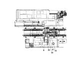
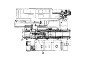
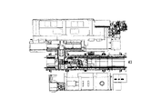
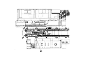
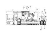
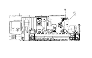
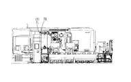
- FIG. 1 is a front view showing a processing system according to one embodiment of the present invention
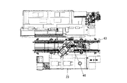
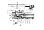
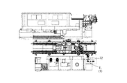
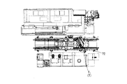
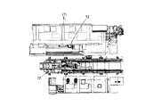
- FIG. It is a top view showing the processing system concerning this embodiment.
- 3 is a view in the direction of arrows AA in FIG. 2
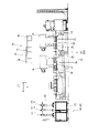
- FIG. 3 is a view showing the moving table and transfer device according to the present embodiment, and is a cross-sectional view corresponding to the view seen from the direction of arrows BB in FIG. 2
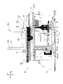
- FIG. 3 is a diagram showing the machine tool according to the present embodiment, taken in the direction of arrows CC in FIG. 2.
- FIG. It is an explanatory view for explaining operation of a conveying system concerning this embodiment. It is an explanatory view for explaining operation of a conveying system concerning this embodiment.
- the tool spindle 12 can hold a turning tool in a fixed state, and can rotatably hold a rotary tool for drilling or milling. (not shown) to move in the X-axis, Y-axis and Z-axis directions.
- the machine tool 10 also includes a tool changer (not shown) having a tool magazine (not shown) in which commonly used tools are stored. is changed by this tool changer.
- the conveying device 41 includes a conveying base 42 arranged along the Z-axis, a moving table 43 arranged on the conveying base 42 and movable along the Z-axis, It is composed of a driving device (not shown) for moving the moving table 43 .
- the transfer base 42 is provided with a guide rail arranged along the Z-axis, and the moving table 43 is guided by the guide rail to move in the Z-axis direction.
- the control device 80 drives the lifting mechanism 60 to lift the second structure 46b of the transfer base 46 (see FIG. 10). As a result, the work W supported by the work support frames 25 , 25 moves upward while being supported by the support members 50 , 50 , and is released from the state of being supported by the work support frames 25 , 25 .
- the control device 80 drives the advancing/retreating mechanism 51 to retract the second transfer table 48 and the third transfer table 49 as shown in FIG. 12, the transfer base 46 is rotated by 90 degrees in the direction of arrow E. As shown in FIG.
- the present invention is not limited to such a mode.
- the work support frames 25, 25 are configured to be lifted and lowered, and after the support members 50, 50 are positioned below the work W, the work support frames 25, 25 are lowered to move the work W to the support members 50, 50. It is good also as an aspect supported by.
Landscapes
- Engineering & Computer Science (AREA)
- Mechanical Engineering (AREA)
- Manipulator (AREA)
Abstract
Description
搬送物を保持する保持装置から該搬送物を取り出して、所定の産業機械に搬送する搬送システムであって、
移動台を有し、該移動台を前記保持装置に対する作業位置と、前記産業機械に対する作業位置とに移動させる搬送装置と、
前記移動台上に配設された移送装置及びロボットと、
前記移動台、移送装置及びロボットの作動を制御する制御装置とを備え、
前記移送装置は、前記搬送物に係合可能に設けられた係合部材、及び該係合部材を水平面内で予め定められた方向に進退させる進退機構を備え、
前記制御装置は、少なくとも、前記搬送装置の移動台を前記保持装置に対して設定された作業位置に移動させる第1移動動作と、前記進退機構により前記係合部材を進出させて、対象となる前記搬送物に係合させる係合動作と、前記進退機構により前記係合部材を後退させて、該搬送物を前記保持装置から取り出す取り出し動作とを順次実行させた後、前記移動台を前記産業機械に対して設定された作業位置に移動させる第2移動動作と、前記進退機構により前記係合部材を進出させて、搬送した搬送物を前記産業機械に搬入する搬入動作と、前記進退機構により前記係合部材を後退させる後退動作とを、順次実行させるように構成された搬送システムに係る。 The present invention for solving the above problems is
A conveying system for taking out a conveyed object from a holding device that holds the conveyed object and conveying the conveyed object to a predetermined industrial machine,
a transport device having a carriage for moving the carriage to a working position with respect to the holding device and a working position with respect to the industrial machine;
a transfer device and a robot disposed on the mobile platform;
A control device for controlling the operation of the mobile platform, the transfer device and the robot,
The transfer device includes an engaging member provided to be able to engage with the conveyed article, and an advance/retreat mechanism for advancing and retreating the engaging member in a predetermined direction in a horizontal plane,
The control device includes at least a first moving operation of moving the moving table of the conveying device to a working position set with respect to the holding device, and advancing the engaging member by the advancing/retreating mechanism to achieve the object. After sequentially executing an engaging operation for engaging the article to be conveyed and an operation for taking out the article from the holding device by retracting the engaging member by the advancing/retracting mechanism, the moving table is moved to the industrial position. a second movement operation for moving the machine to a working position set to the machine; a carrying-in operation for carrying the conveyed article into the industrial machine by advancing the engaging member by the advancing/retreating mechanism; and a retraction operation for retracting the engaging member.
前記制御装置は、前記搬入動作において、前記進退機構により前記係合部材を前記方向とは逆方向に進出させて、搬送した搬送物を前記産業機械に搬入するように構成されていても良い。 In the transport system described above, the advance/retreat mechanism of the transfer device is configured to be capable of advancing the engaging member in the direction and retracting the engaging member to its original position. It is configured to be able to execute an operation to advance the member in a direction opposite to the direction and an operation to retreat to the original position,
The control device may be configured such that, in the carrying-in operation, the advancing/retracting mechanism advances the engaging member in a direction opposite to the above-mentioned direction, and carries the conveyed article into the industrial machine.
前記制御装置は、前記取り出し動作を実行させた後、前記第2移動動作を実行させたときに、前記係合部材の進退方向が前記産業機械に向いた状態となるように、前記旋回機構によって前記係合部材を旋回させる旋回動作を実行させるとともに、前記第2移動動作以降の動作を実行させるように構成されていても良い。 Further, in the transport system, the transfer device further includes a turning mechanism for turning the engaging member around a vertical axis,
The control device causes the turning mechanism to cause the advancing and retreating direction of the engaging member to face the industrial machine when executing the second moving operation after executing the removing operation. It may be configured such that a turning operation for turning the engaging member is executed, and operations after the second moving operation are executed.
前記制御装置は、前記係合動作において、前記進退機構により前記係合部材を進出させた後、前記昇降機構により前記係合部材を上昇させることによって、該係合部材を前記搬送物に係合させるように構成され、更に、前記搬入動作において、前記進退機構により前記係合部材を進出させて、搬送した搬送物を産業機械に搬入した後、前記昇降機構により前記係合部材を降下させるように構成されていても良い。 Further, in the transport system, the transfer device further includes an elevating mechanism for elevating the engaging member,
In the engaging operation, the control device advances the engaging member by the advancing/retreating mechanism, and then raises the engaging member by the lifting mechanism, thereby engaging the engaging member with the article to be conveyed. Further, in the carrying-in operation, the engaging member is advanced by the advancing/retreating mechanism, and after the conveyed article is carried into the industrial machine, the engaging member is lowered by the lifting mechanism. may be configured to
以下、前記ワーク保持装置21に保持されたワークWを、搬送システム40の移送装置45により搬送して、前記工作機械10に供給するワーク搬送動作について、図6~図20に基づいて説明する。尚、図6~図20では、明確性の見地から特に記入した場合を除いて、符号の記入を省略しているが、この図6~図20においても、図1~図5で用いた符号が適用(参照)され、以下では、図1~図5で示した符号を用いて説明する。 [Work transfer operation]
A work conveying operation for conveying the work W held by the
次に、前記工具保持装置30に保持された工具Tを搬送システム40のロボット70により搬送して、前記工作機械10に工具主軸12に装着する工具搬送動作について、図21~図33に基づいて説明する。尚、図21~図33では、明確性の見地から特に記入した場合を除いて、符号の記入を省略しているが、この図21~図33においても、図1~図5で用いた符号が適用(参照)され、以下では、図1~図5で示した符号を用いて説明する。 [Tool transfer operation]
Next, the tool conveying operation of conveying the tool T held by the
10 工作機械
11 チャック
12 工具主軸
13 振止装置
14 支持部材
15 前扉
16 操作盤
20 保持装置
21 ワーク保持装置
22 基台
23 第1ステーション
24 支持台
25 ワーク支持フレーム
26 第2ステーション
27 支持台
28 ワーク支持フレーム
30 工具保持装置
31 基台
32 工具保持フレーム
40 搬送システム
41 搬送装置
42 搬送基台
43 移動台
45 移送装置
46 移送基台
47 第1移送台
48 第2移送台
49 第3移送台
50 支持部材
51 進退機構
52,53,54 ピニオンギア
55,56 ラック
58 旋回機構
60 昇降機構
61 油圧シリンダ
62 ピストン
63,64 供給管
70 ロボット
71 ハンド保持部
75 ハンド収容装置
76,77,78 ハンド保持フレーム
79 フレーム
80 制御装置
Claims (8)
- 搬送物を保持する保持装置から該搬送物を取り出して、所定の産業機械に搬送する搬送システムであって、
移動台を有し、該移動台を前記保持装置に対する作業位置と、前記産業機械に対する作業位置とに移動させる搬送装置と、
前記移動台上に配設された移送装置及びロボットと、
前記移動台、移送装置及びロボットの作動を制御する制御装置とを備え、
前記移送装置は、前記搬送物に係合可能に設けられた係合部材、及び該係合部材を水平面内で予め定められた方向に進退させる進退機構を備え、
前記制御装置は、少なくとも、前記搬送装置の移動台を前記保持装置に対して設定された作業位置に移動させる第1移動動作と、前記進退機構により前記係合部材を進出させて、対象となる前記搬送物に係合させる係合動作と、前記進退機構により前記係合部材を後退させて、該搬送物を前記保持装置から取り出す取り出し動作とを順次実行させた後、前記移動台を前記産業機械に対して設定された作業位置に移動させる第2移動動作と、前記進退機構により前記係合部材を進出させて、搬送した搬送物を前記産業機械に搬入する搬入動作と、前記進退機構により前記係合部材を後退させる後退動作とを、順次実行させるように構成されていることを特徴とする搬送システム。 A conveying system for taking out a conveyed object from a holding device that holds the conveyed object and conveying the conveyed object to a predetermined industrial machine,
a transport device having a carriage for moving the carriage to a working position with respect to the holding device and a working position with respect to the industrial machine;
a transfer device and a robot disposed on the mobile platform;
A control device for controlling the operation of the mobile platform, the transfer device and the robot,
The transfer device includes an engaging member provided to be able to engage with the conveyed article, and an advance/retreat mechanism for advancing and retreating the engaging member in a predetermined direction in a horizontal plane,
The control device includes at least a first moving operation of moving the moving table of the conveying device to a working position set with respect to the holding device, and advancing the engaging member by the advancing/retreating mechanism to achieve the object. After sequentially executing an engaging operation for engaging the article to be conveyed and an operation for taking out the article from the holding device by retracting the engaging member by the advancing/retracting mechanism, the moving table is moved to the industrial position. a second movement operation for moving the machine to a working position set to the machine; a carrying-in operation for carrying the conveyed article into the industrial machine by advancing the engaging member by the advancing/retreating mechanism; and a retraction operation for retracting the engaging member. - 前記移送装置の進退機構は、前記係合部材を前記方向に向けて進出させる動作と、元の位置に後退させる動作とを実行可能に構成されるとともに、更に、前記係合部材を前記方向とは逆方向に向けて進出させる動作と、元の位置に後退させる動作とを実行可能に構成され、
前記制御装置は、前記搬入動作において、前記進退機構により前記係合部材を前記方向とは逆方向に進出させて、搬送した搬送物を前記産業機械に搬入するように構成されていることを特徴とする請求項1記載の搬送システム。 The advance/retreat mechanism of the transfer device is configured to be capable of performing an operation of advancing the engaging member in the direction and an operation of retracting the engaging member to the original position, and further moving the engaging member in the direction. is configured to be capable of advancing in the opposite direction and retracting to its original position,
The control device is configured to advance the engaging member in a direction opposite to the direction by the advance/retreat mechanism in the carrying-in operation so that the conveyed article is carried into the industrial machine. The transport system according to claim 1, wherein: - 前記移送装置は、前記係合部材を鉛直軸回りに旋回させる旋回機構を更に備え、
前記制御装置は、前記取り出し動作を実行させた後、前記第2移動動作を実行させたときに、前記係合部材の進退方向が前記産業機械に向いた状態となるように、前記旋回機構によって前記係合部材を旋回させる旋回動作を実行させるとともに、前記第2移動動作以降の動作を実行させるように構成されていることを特徴とする請求項1記載の搬送システム。 The transfer device further comprises a turning mechanism for turning the engaging member around a vertical axis,
The control device causes the turning mechanism to cause the advancing and retreating direction of the engaging member to face the industrial machine when executing the second moving operation after executing the removing operation. 2. The conveying system according to claim 1, wherein a turning operation for turning the engaging member is executed, and operations after the second moving operation are executed. - 前記制御装置は、前記旋回動作と第2移動動作とを、並行して実行させるように構成されていることを特徴とする請求項3記載の搬送システム。 The transport system according to claim 3, wherein the control device is configured to execute the turning motion and the second moving motion in parallel.
- 前記移送装置は、前記係合部材を昇降させる昇降機構を更に備え、
前記制御装置は、前記係合動作において、前記進退機構により前記係合部材を進出させた後、前記昇降機構により前記係合部材を上昇させることによって、該係合部材を前記搬送物に係合させるように構成され、更に、前記搬入動作において、前記進退機構により前記係合部材を進出させて、搬送した搬送物を産業機械に搬入した後、前記昇降機構により前記係合部材を降下させるように構成されていることを特徴とする請求項1から4のいずれか1項に記載の搬送システム。 The transfer device further includes an elevating mechanism that elevates the engaging member,
In the engaging operation, the control device advances the engaging member by the advancing/retreating mechanism, and then raises the engaging member by the lifting mechanism, thereby engaging the engaging member with the article to be conveyed. Further, in the carrying-in operation, the engaging member is advanced by the advancing/retreating mechanism, and after the conveyed article is carried into the industrial machine, the engaging member is lowered by the lifting mechanism. 5. The conveying system according to any one of claims 1 to 4, characterized in that it is configured as follows. - 前記制御装置は、前記搬送装置及び前記移送装置の動作と、前記ロボットの動作との、少なくとも一部の動作が並行して実行されるように、前記搬送装置及び前記移送装置と、前記ロボットとを、動作させるように構成されていることを特徴とする請求項1から5のいずれか1項に記載の搬送システム。 The control device controls the transfer device, the transfer device, and the robot so that at least part of the actions of the transfer device and the transfer device and the action of the robot are executed in parallel. 6. A transport system according to any one of claims 1 to 5, characterized in that it is arranged to operate the .
- 前記搬送装置は、前記移動台を前記産業機械に対して設定された作業位置から離隔した退避位置に移動可能に構成されていることを特徴とする請求項1から6のいずれか1項に記載の搬送システム。 7. The transfer device according to any one of claims 1 to 6, wherein the transfer table is configured to be movable to a retracted position separated from a working position set with respect to the industrial machine. transport system.
- 前記搬送装置は、前記移動台を前記保持装置に対して設定された作業位置から離隔した退避位置に移動可能に構成されていることを特徴とする請求項1から6のいずれか1項に記載の搬送システム。
7. The conveying device according to any one of claims 1 to 6, wherein the moving table is configured to be able to move to a retracted position separated from a working position set with respect to the holding device. transport system.
Priority Applications (5)
| Application Number | Priority Date | Filing Date | Title |
|---|---|---|---|
| US18/552,126 US20240173810A1 (en) | 2021-03-24 | 2021-03-24 | Conveyance system |
| JP2023508268A JPWO2022201369A1 (en) | 2021-03-24 | 2021-03-24 | |
| CN202180096168.5A CN117083233A (en) | 2021-03-24 | 2021-03-24 | Conveying system |
| PCT/JP2021/012298 WO2022201369A1 (en) | 2021-03-24 | 2021-03-24 | Conveyance system |
| EP21932979.4A EP4306260A1 (en) | 2021-03-24 | 2021-03-24 | Conveyance system |
Applications Claiming Priority (1)
| Application Number | Priority Date | Filing Date | Title |
|---|---|---|---|
| PCT/JP2021/012298 WO2022201369A1 (en) | 2021-03-24 | 2021-03-24 | Conveyance system |
Publications (1)
| Publication Number | Publication Date |
|---|---|
| WO2022201369A1 true WO2022201369A1 (en) | 2022-09-29 |
Family
ID=83396611
Family Applications (1)
| Application Number | Title | Priority Date | Filing Date |
|---|---|---|---|
| PCT/JP2021/012298 WO2022201369A1 (en) | 2021-03-24 | 2021-03-24 | Conveyance system |
Country Status (5)
| Country | Link |
|---|---|
| US (1) | US20240173810A1 (en) |
| EP (1) | EP4306260A1 (en) |
| JP (1) | JPWO2022201369A1 (en) |
| CN (1) | CN117083233A (en) |
| WO (1) | WO2022201369A1 (en) |
Citations (4)
| Publication number | Priority date | Publication date | Assignee | Title |
|---|---|---|---|---|
| JPS6229203U (en) * | 1985-08-05 | 1987-02-21 | ||
| JP2007210757A (en) * | 2006-02-09 | 2007-08-23 | Shibaura Mechatronics Corp | Substrate carrier, display panel manufacturing device using the same; and substrate carrying method, and display panel manufacturing method using the same |
| JP2009184826A (en) | 2008-01-07 | 2009-08-20 | Shin Meiwa Ind Co Ltd | Forklift |
| JP2016540374A (en) * | 2013-10-18 | 2016-12-22 | ブルックス オートメーション インコーポレイテッド | Processing equipment |
-
2021
- 2021-03-24 US US18/552,126 patent/US20240173810A1/en active Pending
- 2021-03-24 EP EP21932979.4A patent/EP4306260A1/en active Pending
- 2021-03-24 JP JP2023508268A patent/JPWO2022201369A1/ja active Pending
- 2021-03-24 WO PCT/JP2021/012298 patent/WO2022201369A1/en active Application Filing
- 2021-03-24 CN CN202180096168.5A patent/CN117083233A/en active Pending
Patent Citations (4)
| Publication number | Priority date | Publication date | Assignee | Title |
|---|---|---|---|---|
| JPS6229203U (en) * | 1985-08-05 | 1987-02-21 | ||
| JP2007210757A (en) * | 2006-02-09 | 2007-08-23 | Shibaura Mechatronics Corp | Substrate carrier, display panel manufacturing device using the same; and substrate carrying method, and display panel manufacturing method using the same |
| JP2009184826A (en) | 2008-01-07 | 2009-08-20 | Shin Meiwa Ind Co Ltd | Forklift |
| JP2016540374A (en) * | 2013-10-18 | 2016-12-22 | ブルックス オートメーション インコーポレイテッド | Processing equipment |
Also Published As
| Publication number | Publication date |
|---|---|
| US20240173810A1 (en) | 2024-05-30 |
| CN117083233A (en) | 2023-11-17 |
| JPWO2022201369A1 (en) | 2022-09-29 |
| EP4306260A1 (en) | 2024-01-17 |
Similar Documents
| Publication | Publication Date | Title |
|---|---|---|
| US10632611B2 (en) | Machine tool | |
| CN109843503B (en) | Conveying equipment, control device thereof and loading and unloading method of material processing unit | |
| JP4901884B2 (en) | Machine Tools | |
| CN112278757B (en) | Automatic production process of connecting ring | |
| KR200393854Y1 (en) | Workpiece loading device for lathe | |
| JP2008183705A (en) | Workpiece processing device | |
| JP5524676B2 (en) | Work carry-in / out device and method in machining system | |
| CN215393675U (en) | Flexible automatic installation production line for steel wire thread insert | |
| CN202763081U (en) | Machine tool | |
| JP4842468B2 (en) | Machine tool with automatic supply / discharge device and processing method thereof | |
| WO2022201369A1 (en) | Conveyance system | |
| JP5732855B2 (en) | Work transfer device | |
| CN113523785A (en) | Flexible automatic installation production line for steel wire thread insert | |
| JPH03136734A (en) | Gear head exchanging device | |
| JP4350820B2 (en) | Transport device | |
| WO2023249050A1 (en) | Processing system | |
| KR102459650B1 (en) | Robot-automated machine tool, robot handler used to machine tool and control method for the same | |
| JP2844488B2 (en) | Pallets that can be used for flexible manufacturing systems | |
| KR102493810B1 (en) | Machining center having a linear automatic pallet changer and method of automatically changing pallets in the machining center | |
| CN117206961A (en) | Automatic feeding and discharging device for numerical control lathe and using method of automatic feeding and discharging device | |
| JP2017154226A (en) | Workpiece conveyance system, workpiece conveyance method, and workpiece processing method | |
| JP2003334737A (en) | Work delivery device | |
| JP2024027359A (en) | Conveyance device | |
| KR100632077B1 (en) | device of transfer work for numerical control | |
| JPH0655399A (en) | Workpiece changing device for machine tool |
Legal Events
| Date | Code | Title | Description |
|---|---|---|---|
| 121 | Ep: the epo has been informed by wipo that ep was designated in this application |
Ref document number: 21932979 Country of ref document: EP Kind code of ref document: A1 |
|
| WWE | Wipo information: entry into national phase |
Ref document number: 2023508268 Country of ref document: JP |
|
| WWE | Wipo information: entry into national phase |
Ref document number: 18552126 Country of ref document: US Ref document number: 202180096168.5 Country of ref document: CN |
|
| WWE | Wipo information: entry into national phase |
Ref document number: 2021932979 Country of ref document: EP |
|
| ENP | Entry into the national phase |
Ref document number: 2021932979 Country of ref document: EP Effective date: 20231010 |
|
| NENP | Non-entry into the national phase |
Ref country code: DE |