WO2022201359A1 - Information processing system, information processing device, information processing method, and storage medium - Google Patents
Information processing system, information processing device, information processing method, and storage medium Download PDFInfo
- Publication number
- WO2022201359A1 WO2022201359A1 PCT/JP2021/012244 JP2021012244W WO2022201359A1 WO 2022201359 A1 WO2022201359 A1 WO 2022201359A1 JP 2021012244 W JP2021012244 W JP 2021012244W WO 2022201359 A1 WO2022201359 A1 WO 2022201359A1
- Authority
- WO
- WIPO (PCT)
- Prior art keywords
- subject
- body temperature
- information processing
- lane
- image
- Prior art date
Links
- 230000010365 information processing Effects 0.000 title claims abstract description 158
- 238000003672 processing method Methods 0.000 title claims description 12
- 230000036760 body temperature Effects 0.000 claims abstract description 179
- 238000003384 imaging method Methods 0.000 claims abstract description 75
- 230000003287 optical effect Effects 0.000 claims description 108
- 238000005192 partition Methods 0.000 claims description 33
- 238000004590 computer program Methods 0.000 claims description 10
- 238000004364 calculation method Methods 0.000 description 44
- 238000004891 communication Methods 0.000 description 21
- 238000012986 modification Methods 0.000 description 16
- 230000004048 modification Effects 0.000 description 16
- 238000010586 diagram Methods 0.000 description 7
- 239000000470 constituent Substances 0.000 description 3
- 238000012545 processing Methods 0.000 description 3
- 238000001816 cooling Methods 0.000 description 2
- 230000000694 effects Effects 0.000 description 2
- RFHAOTPXVQNOHP-UHFFFAOYSA-N fluconazole Chemical compound C1=NC=NN1CC(C=1C(=CC(F)=CC=1)F)(O)CN1C=NC=N1 RFHAOTPXVQNOHP-UHFFFAOYSA-N 0.000 description 2
- 238000000034 method Methods 0.000 description 2
- 238000007639 printing Methods 0.000 description 2
- 206010005908 Body temperature conditions Diseases 0.000 description 1
- 238000013459 approach Methods 0.000 description 1
- 238000005516 engineering process Methods 0.000 description 1
- 210000000887 face Anatomy 0.000 description 1
- 230000006870 function Effects 0.000 description 1
- 239000007787 solid Substances 0.000 description 1
- XLYOFNOQVPJJNP-UHFFFAOYSA-N water Substances O XLYOFNOQVPJJNP-UHFFFAOYSA-N 0.000 description 1
Images


Classifications
-
- G—PHYSICS
- G07—CHECKING-DEVICES
- G07C—TIME OR ATTENDANCE REGISTERS; REGISTERING OR INDICATING THE WORKING OF MACHINES; GENERATING RANDOM NUMBERS; VOTING OR LOTTERY APPARATUS; ARRANGEMENTS, SYSTEMS OR APPARATUS FOR CHECKING NOT PROVIDED FOR ELSEWHERE
- G07C9/00—Individual registration on entry or exit
- G07C9/30—Individual registration on entry or exit not involving the use of a pass
- G07C9/32—Individual registration on entry or exit not involving the use of a pass in combination with an identity check
- G07C9/37—Individual registration on entry or exit not involving the use of a pass in combination with an identity check using biometric data, e.g. fingerprints, iris scans or voice recognition
-
- G—PHYSICS
- G01—MEASURING; TESTING
- G01J—MEASUREMENT OF INTENSITY, VELOCITY, SPECTRAL CONTENT, POLARISATION, PHASE OR PULSE CHARACTERISTICS OF INFRARED, VISIBLE OR ULTRAVIOLET LIGHT; COLORIMETRY; RADIATION PYROMETRY
- G01J5/00—Radiation pyrometry, e.g. infrared or optical thermometry
- G01J5/0022—Radiation pyrometry, e.g. infrared or optical thermometry for sensing the radiation of moving bodies
- G01J5/0025—Living bodies
-
- G—PHYSICS
- G07—CHECKING-DEVICES
- G07C—TIME OR ATTENDANCE REGISTERS; REGISTERING OR INDICATING THE WORKING OF MACHINES; GENERATING RANDOM NUMBERS; VOTING OR LOTTERY APPARATUS; ARRANGEMENTS, SYSTEMS OR APPARATUS FOR CHECKING NOT PROVIDED FOR ELSEWHERE
- G07C9/00—Individual registration on entry or exit
- G07C9/10—Movable barriers with registering means
-
- G—PHYSICS
- G07—CHECKING-DEVICES
- G07C—TIME OR ATTENDANCE REGISTERS; REGISTERING OR INDICATING THE WORKING OF MACHINES; GENERATING RANDOM NUMBERS; VOTING OR LOTTERY APPARATUS; ARRANGEMENTS, SYSTEMS OR APPARATUS FOR CHECKING NOT PROVIDED FOR ELSEWHERE
- G07C9/00—Individual registration on entry or exit
- G07C9/30—Individual registration on entry or exit not involving the use of a pass
- G07C9/38—Individual registration on entry or exit not involving the use of a pass with central registration
-
- A—HUMAN NECESSITIES
- A61—MEDICAL OR VETERINARY SCIENCE; HYGIENE
- A61B—DIAGNOSIS; SURGERY; IDENTIFICATION
- A61B5/00—Measuring for diagnostic purposes; Identification of persons
- A61B5/01—Measuring temperature of body parts ; Diagnostic temperature sensing, e.g. for malignant or inflamed tissue
-
- G—PHYSICS
- G01—MEASURING; TESTING
- G01J—MEASUREMENT OF INTENSITY, VELOCITY, SPECTRAL CONTENT, POLARISATION, PHASE OR PULSE CHARACTERISTICS OF INFRARED, VISIBLE OR ULTRAVIOLET LIGHT; COLORIMETRY; RADIATION PYROMETRY
- G01J5/00—Radiation pyrometry, e.g. infrared or optical thermometry
- G01J2005/0077—Imaging
Definitions
- This disclosure provides, for example, an information processing system that includes a thermal camera capable of generating body temperature information indicating the body temperature of a subject by imaging the subject and an information processing device that acquires the body temperature information from the thermal camera, and a thermal camera.
- the present invention relates to a technical field of an information processing device, an information processing method, and a recording medium for acquiring body temperature information from a device.
- Patent Document 1 describes a gate device equipped with a thermosensor that detects heat such as body temperature as a sensing device that detects a passing person.
- Patent Documents 2 to 4 are cited as prior art documents related to this disclosure.
- JP 2019-071126 A Japanese Patent Application Laid-Open No. 2001-257927 JP 2009-043046 A JP 2020-205117 A Japanese Patent Application Laid-Open No. 2020-201999
- the object of this disclosure is to provide an information processing system, an information processing device, an information processing method, and a recording medium aimed at improving the techniques described in prior art documents.
- an imaging range includes a plurality of gate devices respectively arranged in a plurality of lanes through which a subject can pass; a thermal camera capable of generating body temperature information indicating the body temperature of the subject by capturing an image of the subject included in the subject; and an information processing device that acquires the body temperature information from the thermal camera.
- an imaging range includes at least a portion of each of a plurality of lanes through which the subject can pass, and the subject included in the imaging range is imaged.
- an imaging range includes at least a part of each of a plurality of lanes through which the subject can pass, and the subject included in the imaging range is imaged.
- the body temperature image is acquired from a thermal camera capable of generating a body temperature image showing the body temperature of the subject, and the lane through which the subject has passed indicated by the body temperature image among the plurality of lanes is specified as a passing lane.
- the imaging range includes at least a part of each of a plurality of lanes through which the subject can pass, and the subject included in the imaging range is imaged.
- FIG. 1 is a block diagram showing the overall configuration of the information processing system of this embodiment.
- FIG. 2 is a plan view showing arrangement positions of a plurality of optical cameras, a plurality of gate devices, and a thermal camera.
- FIG. 3 is a block diagram showing the configuration of the information processing apparatus of this embodiment.
- FIG. 4 shows an example of the data structure of the entry history DB.
- FIG. 5 is a flow chart showing the overall flow of admission management operations performed by the information processing apparatus.
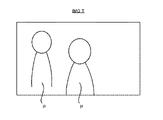
- FIG. 6 schematically shows a thermal image.
- FIG. 7 schematically shows a thermal image divided into multiple image regions.
- FIG. 8 schematically shows a thermal image divided into multiple image regions.
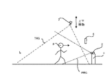
- FIG. 9 is a plan view showing a subject passing through the lane along with an optical camera and a thermal camera.
- FIG. 9 is a plan view showing a subject passing through the lane along with an optical camera and a thermal camera.
- FIG. 10 schematically shows a thermal image.
- FIG. 11 is a plan view showing a plurality of lanes physically separated by partition members.
- FIG. 12 schematically shows a thermal image.
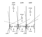
- FIG. 13 shows the arrangement position of the thermal camera in the first modified example.
- FIG. 14 schematically shows the movement of the subject P in the second modified example.
- FIG. 15 schematically shows the movement of the subject P in the second modified example.
- FIG. 16 schematically shows the movement of the subject P in the second modified example.
- FIG. 17 shows the arrangement positions of the optical cameras in the third modified example.
- FIG. 18 is a block diagram showing the configuration of an information processing device in the fourth modification.
- FIG. 19 is a block diagram showing the configuration of an information processing system in the fourth modified example.
- Embodiments of an information processing system, an information processing system, an information processing apparatus, an information processing method, and a recording medium will be described below. Embodiments of the information processing system, the information processing apparatus, the information processing method, and the recording medium will be described below using an information processing system SYS to which the embodiments of the information processing system, the information processing apparatus, the information processing method, and the recording medium are applied. explain.
- FIG. 1 is a block diagram showing the overall configuration of an information processing system SYS of this embodiment.
- FIG. 1 it includes a plurality of gate devices 1, a plurality of optical cameras 2, a thermal camera 3, and an information processing device 4, which is a specific example of an "information processing device.”
- a plurality of gate devices 1 and information processing devices 4 may be able to communicate with each other via communication network 5 .
- the plurality of optical cameras 2 and the information processing device 4 may be able to communicate with each other via the communication network 5 .
- the thermal camera 3 and the information processing device 4 may be able to communicate with each other via the communication network 5 .
- Communication network 5 may include a wired communication network.
- Communication network 5 may include a wireless communication network.
- the gate device 1 is a device that can control the passage of the target person P.
- the state of the gate device 1 can be switched between a closed state in which the subject P cannot pass through the gate device 1 and an open state in which the subject P can pass through the gate device 1 .
- the gate device 1 includes a gate bar 11 (see FIG. 2, which will be described later)
- the state of the gate device 1 includes a closed state in which the gate bar 11 is closed and an open state in which the gate bar 11 is open. It may be switchable between.
- the state of the one gate device 1 through which the target person P is about to pass is switched to the closed state.
- the target person P who does not satisfy the entry conditions cannot enter the management area MA because the target person P cannot pass through the closed gate device 1 .
- the plurality of gate devices 1 may be arranged at positions different from the entrance/exit of the management area MA. In the following description, for convenience of description, an example in which a plurality of gate devices 1 are arranged at the entrance/exit of the management area MA will be described.
- the optical camera 2 is an imaging device capable of optically imaging the subject P located in the imaging range PRG of the optical camera 2 .
- the optical camera 2 captures an image of the subject P to generate a person image IMG_P representing the subject P captured by the optical camera 2 .
- the person image IMG_P representing the target person P may typically be an image in which the target person P is captured.
- the “human image IMG_P in which the target person P is captured” is generated by the optical camera 2 capturing an image of the target person P who does not have the intention of wanting the optical camera 2 to capture the image of the target person P.
- the “human image IMG_P in which the target person P is captured” is an image generated by the optical camera 2 capturing an image of the target person P who has the intention of wanting the optical camera 2 to capture an image of the target person P.
- the optical camera 2 transmits the generated person image IMG_P to the information processing device 4 via the communication network 5 .
- the information processing system SYS includes three gate devices 1 (specifically, gate device 1#1, gate device 1#2, and gate device 1#3). ), and three optical cameras 2 (specifically, optical camera 2#1, optical camera 2#2, and optical camera 2#3).
- each gate device 1 is arranged in one lane L through which the subject P can pass in order to pass through.
- each optical camera 2 has an imaging range PRG of each optical camera 2, at least a part of one lane L through which the subject P can pass in order to pass through one gate device 1 corresponding to each optical camera 2. is placed so as to be contained in
- each optical camera 2 is an area through which the subject P can pass before the subject P passes through one gate device 1 corresponding to each optical camera 2 in the lane L corresponding to each optical camera 2. is arranged so as to be included in the imaging range PRG of each optical camera 2 .
- each optical camera 2 is arranged so as to capture an image of the subject P who is heading toward the gate device 1 corresponding to each optical camera 2 .
- each optical camera 2 is typically arranged at or near the gate device 1 corresponding to each optical camera 2 .
- each optical camera 2 detects a lane portion La through which the subject P passes before passing through the gate device 1 of the lane L corresponding to each optical camera 2 (that is, on one side of the gate device 1). (lane portion where it is located) is arranged so that at least part of it is included in the imaging range PRG.
- each optical camera 2 is located in the lane portion Lb through which the subject P passes after passing through the gate device 1 of the lane L corresponding to each optical camera 2 (that is, the lane portion Lb is located on the other side of the gate device 1).
- lane portion need not be arranged so as to be included in the imaging range PRG. Therefore, each optical camera 2 images the subject P passing through one lane L corresponding to each optical camera 2 before the subject P passes through one gate device 1 corresponding to each optical camera 2.
- optical camera 2#1 is configured such that at least part of lane L#1 through which target person P passing through gate device 1#1 corresponding to optical camera 2#1 can pass is optical camera 2#1.
- the optical camera 2#1 captures an image of the subject P passing through the lane L#1 before the subject P passes through the gate device 1#1.
- the optical camera 2#2 is configured such that at least part of the lane L#2 through which the target person P passing through the gate device 1#2 corresponding to the optical camera 2#2 can pass is the imaging range of the optical camera 2#2. Arranged so as to be included in PRG#2. Therefore, the optical camera 2#2 captures an image of the subject P passing through the lane L#2 before the subject P passes through the gate device 1#2.
- Optical camera 2#3 is configured such that at least part of lane L#3 through which target person P can pass through gate device 1#3 corresponding to optical camera 2#3 is an imaging range PRG# of optical camera 2#3. 3 to be included. Therefore, the optical camera 2#3 captures an image of the subject P passing through the lane L#3 before the subject P passes through the gate device 1#3.
- Lanes L#1 to L#3 do not have to be physically separated (in other words, separated). Lanes L#1 to L#3 may not be physically distinguishable. However, lanes L#1 to L#3 may be physically separated. Lanes L#1 to L#3 may be physically distinguishable. For example, lanes L#1 to L#3 may be physically separated by a structure (for example, a fence or the like) for physically separating lanes L#1 to L#3.
- a structure for example, a fence or the like
- the thermal camera 3 is an imaging device capable of imaging the subject P located in the imaging range TRG of the thermal camera 3 .
- the thermal camera 3 captures an image of the subject P to generate body temperature information indicating the body temperature of the subject P captured by the thermal camera 3 .
- the body temperature information may include image information indicating the subject's body temperature (that is, body temperature image, hereinafter referred to as "thermal image IMG_T").
- the thermal image IMG_T may be an image that indicates the subject's body temperature distribution in color or gradation.
- the body temperature information may include numerical information that quantitatively indicates the subject's body temperature.
- Temperature information may include any data that directly or indirectly indicates the subject's temperature.
- the thermal image IMG_T indicating the body temperature of the subject P may typically be an image in which the subject P is substantially reflected due to the subject's P body temperature distribution.
- the "thermal image IMG_T in which the subject P is captured” is generated by the thermal camera 3 capturing an image of the subject P who does not have the intention of wanting the subject P to be imaged by the thermal camera 3.
- the “body temperature image IMG_T in which the subject P is captured” is an image generated by the thermal camera 3 capturing an image of the subject P who has the intention of wanting the subject P to be imaged by the thermal camera 3.
- the thermal camera 3 transmits the generated thermal image IMG_T (that is, the generated body temperature information) to the information processing device 4 via the communication network 5 .
- the thermal camera 3 is arranged so that at least part of each of the plurality of lanes L is included in the imaging range TRG of the thermal camera 3, as shown in FIG. That is, the thermal camera 3 is configured such that at least part of the lane L#1, at least part of the lane L#2, and at least part of the lane L#3 are included in the imaging range TRG of the thermal camera 3. , are placed. In particular, the thermal camera 3 is configured such that at least a part of the area through which the subject P can pass before the subject P passes through one gate device 1 corresponding to each lane L of the lanes L is covered by the thermal camera. 3 is arranged so as to be included in the imaging range TRG of No. 3.
- the thermal camera 3 is arranged so as to capture an image of the target person P coming toward the gate device 1 .
- the thermal camera 3 is typically arranged at or near any one of the plurality of gate devices 1 . Therefore, the thermal camera 3 captures an image of the subject P passing through each lane L corresponding to each gate device 1 before the subject P passes through each gate device 1 .
- the thermal camera 3 captures an image of the subject P passing through the lane L#1 before the subject P passes through the gate device 1#1.
- the thermal camera 3 captures an image of the subject P passing through the lane L#2 before the subject P passes through the gate device 1#2.
- the thermal camera 3 captures an image of the subject P passing through the lane L#3 before the subject P passes through the gate device 1#3.
- the information processing device 4 acquires a person image IMG_P from at least one of the multiple optical cameras 2 . Further, the information processing device 4 acquires a thermal image IMG_T (that is, body temperature information) from the thermal camera 3 . The information processing device 4 performs a desired operation based on the acquired person image IMG_P and thermal image IMG_T (that is, body temperature information).
- the information processing device 4 performs an entrance management operation for managing the entrance of the target person P to the management area MA in which the gate devices 1#1 to 1#3 are arranged.
- the entrance management operation includes an operation of authenticating the target person P appearing in the person image IMG_P (that is, determining whether or not the target person P matches a registered person) based on the person image IMG_P. good too.
- the entry conditions that the target person P must satisfy in order to enter the management area MA include the authentication condition that the target person P has been successfully authenticated (that is, the target person P matches the registered person). good.
- the admission management operation identifies the body temperature of the authenticated subject P based on the thermal image IMG_T, and determines whether the identified body temperature is normal (typically, lower than the allowable upper limit). It may include an operation of determining.
- the entry conditions that the subject P must satisfy in order to enter the management area MA may include a body temperature condition that the body temperature of the subject P is normal.
- FIG. 3 is a block diagram showing the configuration of the information processing device 4. As shown in FIG.
- the information processing device 4 includes an arithmetic device 41, a storage device 42, and a communication device 43. Furthermore, the information processing device 4 may include an input device 44 and an output device 45 . However, the information processing device 4 may not include at least one of the input device 44 and the output device 45 . Arithmetic device 41 , storage device 42 , communication device 43 , input device 44 , and output device 45 may be connected via data bus 46 .
- the computing device 41 includes, for example, at least one of a CPU (Central Processing Unit), a GPU (Graphics Processing Unit), and an FPGA (Field Programmable Gate Array). Arithmetic device 41 reads a computer program. For example, arithmetic device 41 may read a computer program stored in storage device 42 . For example, the computing device 41 may read a computer program stored in a computer-readable non-temporary recording medium using a recording medium reading device (not shown) included in the information processing device 4 . The computing device 41 may acquire (that is, download) a computer program from a device (not shown) arranged outside the information processing device 4 via the communication device 43 (or other communication device). may be read). Arithmetic device 41 executes the read computer program.
- a CPU Central Processing Unit
- GPU Graphics Processing Unit
- FPGA Field Programmable Gate Array
- logical functional blocks for executing the operations (for example, the entrance control operation described above) that should be performed by the information processing device 4 are implemented in the arithmetic unit 41 .
- the arithmetic unit 41 can function as a controller for realizing logical functional blocks for executing operations (in other words, processing) that the information processing apparatus 4 should perform.
- FIG. 3 shows an example of logical functional blocks implemented within the computing device 41 to execute the admission control operation.
- the computing device 41 includes an image acquisition unit 411 as a specific example of "acquisition means”, an authentication unit 412 as a specific example of “authentication means”, and an “identification means”.
- a body temperature calculation unit 413 which is a specific example
- an entrance management unit 414 which is a specific example of the “generating means”.
- the operations of the image acquisition unit 411, the authentication unit 412, the body temperature calculation unit 413, and the entrance management unit 414 will be described in detail later, but the outline thereof will be briefly described here.
- the image acquisition unit 411 acquires the person image IMG_P from at least one of the multiple optical cameras 2 .
- the image acquisition unit 411 acquires a thermal image IMG_T from the thermal camera 3 .
- Authentication unit 412 authenticates subject P appearing in person image IMG_P based on person image IMG_P (that is, determines whether subject P matches a registered person).
- the body temperature calculation unit 413 calculates the body temperature of the subject P authenticated by the authentication unit 412 based on the thermal image IMG_T.
- the entrance management unit 414 manages the entrance of the target person P to the management area MA. Furthermore, the entrance management unit 414 generates an entrance history DB (DataBase) 421 for managing the entrance history of the target person P to the management area MA.
- DataBase DataBase
- the history record 4210 includes identification information 4211 for identifying the subject P, time information 4212 indicating the time when the subject P was authenticated, body temperature information 4213 indicating the body temperature of the subject P, and Gate information 4214 for identifying the gate device 1 through which the target person P passed (or through which the target person P was going to pass), and entrance permission information 4215 indicating whether or not the target person P is permitted to enter may be included.
- the identification information 4211 for identifying the subject P and the body temperature information 4213 indicating the body temperature of the subject P are associated.
- information indicating the name of the subject P is used as the identification information 4211 .
- the storage device 42 can store desired data.
- the storage device 42 may temporarily store computer programs executed by the arithmetic device 41 .
- the storage device 42 may temporarily store data temporarily used by the arithmetic device 41 while the arithmetic device 41 is executing a computer program.
- the storage device 42 may store data that the information processing device 4 saves over a long period of time.
- the storage device 42 may store an entrance history DB 421 .
- the storage device 42 may include at least one of RAM (Random Access Memory), ROM (Read Only Memory), hard disk device, magneto-optical disk device, SSD (Solid State Drive), and disk array device. good. That is, the storage device 42 may include non-transitory recording media.
- the communication device 43 can communicate with each of the plurality of optical cameras 2 and thermal cameras 3 via the communication network 5 .
- the communication device 43 receives (that is, acquires) the person image IMG_P from at least one of the plurality of optical cameras 2 via the communication network 5 .
- the communication device 43 receives (that is, acquires) the thermal image IMG_T from the thermal camera 3 via the communication network 5 .
- the input device 44 is a device that receives input of information to the information processing device 4 from the outside of the information processing device 4 .
- the input device 44 may include an operating device (for example, at least one of a keyboard, a mouse, and a touch panel) that can be operated by an operator of the information processing device 4 .
- the input device 44 may include a reading device capable of reading information recorded as data on a recording medium that can be externally attached to the information processing device 4 .
- the output device 45 is a device that outputs information to the outside of the information processing device 4 .
- the output device 45 may output information as an image.
- the output device 45 may include a display device (so-called display) capable of displaying an image showing information to be output.
- the output device 45 may output the information as voice.
- the output device 45 may include an audio device capable of outputting audio (so-called speaker).
- the output device 45 may output information on paper.
- the output device 45 may include a printing device (so-called printer) capable of printing desired information on paper.
- FIG. 5 is a flow chart showing the overall flow of admission management operations performed by the information processing device 4 .
- the image acquisition unit 411 acquires a human image IMG_P from at least one of the plurality of optical cameras 2 (step S1).
- the authentication unit 412 authenticates the subject P appearing in the person image IMG_P acquired in step S1 based on the person image IMG_P acquired in step S1 (step S2).
- authentication unit 412 recognizes target person P passing lane L#1 (that is, gate device 1#1) based on person image IMG_P acquired from optical camera 2#1.
- a subject P) facing the device 1#1 is authenticated.
- authentication unit 412 determines target person P passing lane L#2 (that is, gate device 1 to pass gate device 1#2) based on person image IMG_P acquired from optical camera 2#2.
- authentication unit 412 recognizes target person P passing lane L#3 (that is, gate device 1 to pass through gate device 1#3) based on person image IMG_P acquired from optical camera 2#3. Authenticate the subject P) heading for #3.
- the authentication unit 412 may perform a face authentication operation to authenticate the target person P using the feature points of the target person P's face reflected in the person image IMG_P.
- the authentication unit 412 may perform an iris authentication operation of authenticating the target person P using the feature points of the iris of the target person P reflected in the person image IMG_P.
- the image acquisition unit 411 acquires a thermal image IMG_T from the thermal camera 3 (step S3). Thereafter, the body temperature calculator 413 calculates the body temperature of the subject P authenticated in step S2 based on the thermal image IMG_T acquired in step S3 (step S4).
- the imaging range TRG of the thermal camera 3 includes at least part of each of the plurality of lanes L.
- the thermal image IMG_T includes the subject P who is passing through any one of the lanes #1 to L#3, and the subject P from the lane #1.
- the target person P who is passing through any other one of L#3 will be photographed at the same time. That is, there is a possibility that a plurality of subjects P passing through a plurality of different lanes L will appear in the thermal image IMG_T.
- the body temperature calculation unit 413 calculates the body temperature of one lane through which each subject P appearing in the thermal image IMG_T passes. Identify L. Based on the thermal image IMG_T, the body temperature calculation unit 413 calculates the body temperature of each subject P whose passing lane L is specified by the optical camera corresponding to the specified lane L. 2 is calculated as the body temperature of the authenticated subject P based on the person image IMG_P acquired from 2. Specifically, when the person image IMG_P is acquired from the optical camera 2#1 in step S2, the subject P appearing in the person image IMG_P is passing through the lane L#1.
- the body temperature calculation unit 413 identifies one lane L through which each subject P appearing in the thermal image IMG_T passes through, so that the lane L#1 is passed through in the thermal image IMG_T.
- the target person P is identified, and the body temperature of the identified target person P is measured by the target person P passing through the lane L#1 (that is, the target person reflected in the human image IMG_P acquired by the optical camera 2#1).
- P) is calculated as body temperature.
- the person image IMG_P is acquired from the optical camera 2#2 or 2#3 in step S2.
- the body temperature calculation unit 413 can capture images of the plurality of subjects P who pass through a plurality of different lanes L, respectively. body temperature can be calculated appropriately.
- the entrance management unit 414 determines whether or not the subject P appearing in the person image IMG_P acquired in step S1 is permitted to enter the management area MA (step S6). Specifically, the entrance management unit 414 confirms that the subject P has been successfully authenticated in step S2, and that the body temperature of the subject P calculated in step S4 is normal (typically, it is higher than the allowable upper limit). is low), it may be determined that the subject P is permitted to enter the management area MA.
- the admission management unit 414 determines that the authentication of the subject P was not successful in step S2 and/or the body temperature of the subject P calculated in step S4 is not normal (typically, the allowable upper limit value higher), it may be determined that the target person P is not permitted to enter the management area MA.
- step S6 if it is determined that the target person P is permitted to enter the management area MA (step S6: Yes), the entrance management unit 414 controls the one gate device through which the target person P is going to pass. 1 (that is, one gate device 1 corresponding to one optical camera 2 that generated the person image IMG_P in which the subject P is captured) is the open state. control (step S7).
- the entrance management unit 414 may transmit a control signal for setting the state of the one gate device 1 to the open state to the one gate device 1 via the communication network 5 .
- the target person P can enter the management area MA by passing through the gate device 1 in the open state.
- step S6 if it is determined that the subject P is not permitted to enter the management area MA (step S6: No), the entrance management unit 414 determines that the subject P is about to pass through.
- the one gate device 1 that is, the one gate device 1 corresponding to the one optical camera 2 that generated the person image IMG_P in which the subject P is captured
- the entrance management unit 414 may transmit a control signal for setting the state of the one gate device 1 to the closed state to the one gate device 1 via the communication network 5 .
- the target person P cannot enter the management area MA because the target person P cannot pass through the gate device 1 in the closed state.
- the entrance management unit 414 updates the entrance history DB 421 (step S9). Specifically, the entrance management unit 414 stores information about the authentication result of the subject P in step S2 (specifically, the identification information 4211, the time information 4212, and the gate information 4214 described above), and the information calculated in step S4. A new history record 4210 containing information about the body temperature of the subject P (specifically, the body temperature information 4213) and information about the determination result in step S6 (specifically, the admission permission information 4215) is stored in the admission history DB 421. Add to
- FIG. 7 schematically shows a thermal image IMG_T.
- the body temperature calculation unit 413 divides the thermal image IMG_T into a plurality of image regions TR ( Specifically, it is divided into image regions TR#1 to TR#3).
- An image region TR#1 is an image region in which the subject P passing through the lane L#1 is assumed to appear in the thermal image IMG_T.
- An image region TR#2 is an image region in which the subject P passing through the lane L#2 is assumed to appear in the thermal image IMG_T.
- An image region TR#3 is an image region in which the subject P passing through the lane L#3 is assumed to appear in the thermal image IMG_T.
- the body temperature calculation unit 413 determines whether each subject P passes through one lane L corresponding to one image region TR in which each subject P is captured, out of the image regions TR#1 to TR#3.
- Lane L is identified as the one lane L in which the For example, in the example shown in FIG. 7, the target person P#a is reflected in the image region TR#1, and the target person P#b is reflected in the image region TR#2.
- body temperature calculation unit 413 identifies lane #1 as lane L through which subject P#a is passing.
- the body temperature calculation unit 413 calculates the body temperature of the subject P#a appearing in the thermal image IMG_T from the subject P (that is, the optical camera) passing through the lane L#1. 2#1 is calculated as the body temperature of the subject P) appearing in the person image IMG_P acquired from 2#1. Similarly, body temperature calculation unit 413 identifies lane #2 as lane L through which subject P#b is passing. As a result, based on the thermal image IMG_T, the body temperature calculation unit 413 calculates the body temperature of the subject P#b appearing in the thermal image IMG_T, and calculates the body temperature of the subject P (that is, the optical camera) passing through the lane L#2. 2#2 is calculated as the body temperature of the subject P) appearing in the person image IMG_P acquired from 2#2.
- the body temperature calculation unit 413 calculates the arrangement positions of the lanes L#1 to L#3 (that is, the arrangement positions of the gate devices 1#1 to 1#3), the arrangement positions of the thermal cameras 3, and the optical characteristics of the thermal cameras 3 ( For example, the thermal image IMG_T may be divided into image regions TR#1 to TR#3 based on the imaging range TRG). Therefore, in the first specific example, the arrangement positions of the lanes L#1 to L#3 (that is, the arrangement positions of the gate devices 1#1 to 1#3), the arrangement positions of the thermal cameras 3, and the thermal cameras 3
- the information about the optical characteristics is preferably information known to the body temperature calculator 413 .
- At least one characteristic of the image regions TR#1 to TR#3 may be fixed.
- the characteristics of the image area TR may include at least one of the size of the image area TR and the shape of the image area TR.
- the body temperature calculator 413 may make at least one characteristic of the image regions TR#1 to TR#3 variable.
- the arrangement positions of the lanes L#1 to L#3 that is, the arrangement positions of the gate devices 1#1 to 1#3
- the arrangement position of the thermal camera 3 for example, the imaging range TRG
- the body temperature calculator 413 may change at least one characteristic of the image regions TR#1 to TR#3.
- FIG. 7 shows an example of image areas TR#1 to TR#3 when the thermal camera 3 is arranged in lane L#2 located between lane L#1 and lane L#3. is shown.
- the body temperature calculation unit 413 converts the thermal image IMG_T into a diagram having characteristics different from those of the image regions TR#1 to TR#3 shown in FIG. 8 may be divided into image areas TR#1 to TR#3.
- FIG. 9 is a plan view showing subjects P#1 to P#3 passing through lanes L#1 to L#3, respectively, together with optical cameras 2#1 to 2#3 and thermal camera 3.
- FIG. 9 is a plan view showing subjects P#1 to P#3 passing through lanes L#1 to L#3, respectively, together with optical cameras 2#1 to 2#3 and thermal camera 3.
- optical cameras 2#1 to 2#3 capture images of subjects P#1 to P#3 who are passing through lanes L#1 to L#3, respectively.
- body temperature calculation unit 413 arranges lanes L#1 to L#3 based on human image IMG_P generated by optical camera 2#k (where k is a variable representing 1, 2, or 3). (that is, where the gate devices 1#1 to 1#3 are arranged), the position of the subject P#k appearing in the person image IMG_P is calculated in the world coordinate system for representing the position in the space. do.
- the body temperature calculation unit 413 calculates the position in the person image IMG_P within the person image coordinate system: The position of the right eye (or other part different from the right eye) of the subject P#k is calculated.
- the body temperature calculation unit 413 calculates the position of the right eye of the subject P#k, the arrangement positions of the lanes L#1 to L#3 (that is, the arrangement positions of the gate devices 1#1 to 1#3), and the optical camera Based on the arrangement position of 2#k, the optical characteristics of optical camera 2#k (for example, imaging range PRG#k), and the average inter-eye distance (that is, the average value of the distance between human eyes), Calculate the position of the subject P#k in the world coordinate system.
- the body temperature calculation unit 413 determines whether or not the target person P#k appearing in the person image IMG_P is the target person P passing through the lane L#k (that is, whether or not the target person P is placed in the lane L#k It is possible to determine with high accuracy whether or not the target person P is facing the gate device 1#k. That is, a subject different from the subject P#k (specifically, a subject passing through a lane L different from the lane L#k) appears in the human image IMG_P generated by the optical camera 2#k. Even when the target person P#k is passing through the lane L#k, it is possible to extract the target person P#k from the person image IMG_P.
- Patent Literature 5 An example of technology for extracting the target person P#k passing through the lane L#k is described in Patent Literature 5, for example.
- the body temperature calculation unit 413 calculates the timing at which the subject P#k passes through the lane L#k based on the position of the subject P#k in the world coordinate system. Specifically, body temperature calculation unit 413 determines the timing at which target person P#k reaches gate device 1#k arranged in lane L#k based on the position of target person P#k in the world coordinate system. calculate. After that, the body temperature calculation unit 413 identifies one lane L through which each subject P appearing in the thermal image IMG_T is passing, based on the calculated timing and the thermal image IMG_T. Specifically, as shown in FIG.
- the body temperature calculation unit 413 calculates the timings at which the subjects P#1 to P#3 reach the gate devices 1#1 to 1#3, respectively, so that the subject P#2 is at the gate.
- the timing of reaching the device 1#2 is the earliest
- the timing of the target person P#3 reaching the gate device 1#3 is the second earliest
- the timing of the target person P#1 reaching the gate device 1#1 is the fastest. perceive it as late.
- the target person P#a is reflected so as to exist on the frontmost side.
- the body temperature calculation unit 413 determines that the target person P#a reflected in the thermal image IMG_T passes through the lane L#2 through which the target person P#2, who reaches the gate device 1 at the earliest timing, passes through. It is specified as one lane L that is As a result, based on the thermal image IMG_T, the body temperature calculation unit 413 calculates the body temperature of the subject P#a appearing in the thermal image IMG_T, and calculates the body temperature of the subject P#2 passing through the lane L#2 (that is, It is calculated as the body temperature of the subject P#2) captured in the person image IMG_P acquired from the optical camera 2#2. In addition, in the thermal image IMG_T shown in FIG.
- the body temperature calculation unit 413 determines that the lane L#3 through which the target person P#3, who arrives at the gate device 1 at the second earliest timing, is passing is the target person P#b reflected in the thermal image IMG_T. is identified as one lane L through which As a result, based on the thermal image IMG_T, the body temperature calculation unit 413 calculates the body temperature of the subject P#b appearing in the thermal image IMG_T, and calculates the body temperature of the subject P#3 passing through the lane L#3 (that is, It is calculated as the body temperature of the subject P#3) captured in the person image IMG_P acquired from the optical camera 2#3.
- the body temperature calculation unit 413 determines that the target person P#c reflected in the thermal image IMG_T passes through the lane L#1 through which the target person P#1 who arrives at the gate device 1 the latest is passing. It is specified as one lane L that is As a result, based on the thermal image IMG_T, the body temperature calculation unit 413 calculates the body temperature of the subject P#c reflected in the thermal image IMG_T from the subject P#1 (that is, the body temperature of the subject P#1 passing through the lane L#1). It is calculated as the body temperature of the subject P#1) captured in the person image IMG_P acquired from the optical camera 2#1.
- the body temperature calculation unit 413 calculates the position of the subject P reflected in the thermal image IMG_T in the world coordinate system based on the thermal image IMG_T.
- the operation of calculating the position of the subject P appearing in the thermal image IMG_T may be the same as the operation of calculating the position of the subject P appearing in the person image IMG_P described in the second specific example. .
- the body temperature calculation unit 413 calculates the right eye (or other part different from the right eye) of the subject P#k within the thermal image coordinate system for representing the position within the thermal image IMG_T. ) may be calculated. After that, the body temperature calculation unit 413 calculates the position of the subject P#k's right eye, the arrangement positions of the lanes L#1 to L#3 (that is, the arrangement positions of the gate devices 1#1 to 1#3), and the thermal camera 3, the optical characteristics of the thermal camera 3 (for example, the imaging range TRG), and the average distance between the eyes (that is, the average value of the distance between the human eyes), the subject in the world coordinate system The position of P#k may be calculated.
- the body temperature calculation unit 413 determines whether or not the subject P reflected in the thermal image IMG_T is the subject P passing through the lane L#k (that is, whether the subject P is placed in the lane L#k). (whether or not the target person P is facing the gate device 1#k) can be determined with high accuracy. That is, the body temperature calculation unit 413 can highly accurately identify the lane L through which the subject P appearing in the thermal image IMG_T passes.
- the body temperature calculator 413 substantially calculates the distance between the thermal camera 3 and the subject P. That is, it can be said that the body temperature calculator 413 substantially calculates the distance between the gate device 1 and the subject P.
- the body temperature calculator 413 may perform an operation considering the distance between the gate device 1 and the subject P. For example, the body temperature calculation unit 413 calculates the body temperature of the subject P who is reflected in the thermal image IMG_T and approaches the gate device 1 so that the distance between the gate device 1 and the subject P becomes less than a predetermined distance.
- the body temperature calculation unit 413 calculates the body temperature of the subject P who is reflected in the thermal image IMG_T and who is farther from the gate device 1 as the distance between the gate device 1 and the subject P becomes larger than the predetermined distance. No need to calculate. This is because it takes a long time for the subject P to reach the gate device 1, so the need to calculate the body temperature of the subject P is relatively low.
- the shorter the distance between the gate device 1 and each subject P the closer each subject P appears in the thermal image IMG_T. enter.
- the shorter the distance between the thermal camera 3 and each subject P the larger the size of each subject P captured in the thermal image IMG_T. Therefore, it can be said that the state (for example, size) of the subject P reflected in the thermal image IMG_T includes information about the distance between the gate device 1 and the subject P. Therefore, the body temperature calculation unit 413 does not calculate the position of the subject P in the world coordinate system based on the thermal image IMG_T. , the operation may be performed in consideration of the distance between the gate device 1 and the subject P.
- FIG. 11 is a plan view showing lanes L#1 to L#3.
- two adjacent lanes L among lanes L#1 to L#3 are physically separated by a partition member BD.
- adjacent lanes L#1 and L#2 are physically separated by a partition member BD#12 arranged at the boundary between lanes L#1 and L#2.
- Adjacent lanes L#2 and L#3 are physically separated by a partition member BD#23 arranged on the boundary between lanes L#2 and L#3.
- the temperature of the partition member BD is set to a temperature different from the temperature of the space in which the lanes L#1 to L#3 are arranged (that is, the gate devices 1#1 to 1#3 are arranged).
- the partition member BD may be a member that is not easily affected by the temperature of the space in which the partition member BD is arranged. In this case, even if the operation for adjusting the temperature of the partition member BD is not performed, the temperature of the partition member BD may become different from the temperature of the space in which the partition member BD is arranged. get higher
- the temperature of the partition member BD may be adjusted by a temperature adjustment device capable of adjusting the temperature of the partition member BD.
- the temperature control device may comprise at least one of an air cooling device and a water cooling device.
- the temperature adjustment device may adjust the temperature of the partition member BD so that the temperature of the partition member BD is different from the temperature of the space in which the partition member BD is arranged.
- the partition member BD When the partition member BD is arranged, not only the subject P but also the partition member BD are reflected in the thermal image IMG_T. In this case, as shown in FIG. 12 showing a thermal image IMG_T in which the partition member BD is reflected, the partition member BD is reflected in the thermal image IMG_T in a manner in which the partition member BD can be identified. This is because, as described above, the temperature of the partition member BD is different from the temperature of the space in which the partition member BD is arranged.
- the body temperature calculation unit 413 selects one lane L through which the subject P in the thermal image IMG_T passes.
- the body temperature calculation unit 413 calculates one lane L through which the subject P appearing in the thermal image IMG_T passes based on the position of the partition member BD and the position of the subject P in the thermal image IMG_T. can be specified. For example, in the example shown in FIG. 12, when the subject P is reflected to the left of the partition member BD#12 in the thermal image IMG_T, the body temperature calculation unit 413 selects the lane L#1 as the subject P.
- the body temperature calculation unit 413 assigns the lane L#2 to the subject P can be identified as one lane L through which the body temperature calculation unit 413 selects the lane L#3 as the subject P is passing. can be identified as Lane L.
- the thermal camera 3 can image a plurality of subjects P passing through each of the plurality of lanes L.
- the information processing system SYS does not have to include a plurality of thermal cameras 3 each including a plurality of lanes L in the imaging range TRG.
- the information processing system SYS does not have to include a plurality of thermal cameras 3 that capture images of a plurality of subjects P passing through a plurality of lanes L, respectively. Therefore, the cost of the information processing system SYS can be reduced.
- the information processing device 4 also identifies one lane L through which each target person P appearing in the thermal image IMG_T is passing. Therefore, even when the thermal camera 3 captures images of a plurality of subjects P who pass through a plurality of different lanes L, the body temperature calculation unit 413 can detect the images of the plurality of subjects P who pass through a plurality of different lanes L. body temperature can be calculated appropriately.
- the information processing device 4 divides the thermal image IMG_T into a plurality of image regions TR, and selects one lane L corresponding to one image region TR in which the target person P is captured among the plurality of image regions TR. , may be specified as one lane L through which the subject P who is reflected in the thermal image IMG_T is passing. In this case, the information processing device 4 can relatively easily identify one lane L through which the target person P is passing.
- the information processing device 4 calculates, based on the person image IMG_P, the timing at which the target person P appearing in the person image IMG_P reaches the gate device 1, and based on the calculated timing, One lane L through which the crowded subject P is passing may be identified. In this case, the information processing device 4 can identify, with relatively high accuracy, one lane L through which the target person P is passing.
- the information processing device 4 calculates the position in the world coordinate system of the subject P appearing in the thermal image IMG_T based on the thermal image IMG_T, and based on the calculated position, the information processing apparatus 4 does not appear in the thermal image IMG_T.
- One lane L through which the target person P is passing may be identified.
- the information processing device 4 can identify, with relatively high accuracy, one lane L through which the target person P is passing.
- the information processing device 4 identifies one lane L through which the subject P appearing in the thermal image IMG_T is passing, based on the positional relationship between the partition member BD and the subject P in the thermal image IMG_T. You may In this case, the information processing device 4 can identify the one lane L through which the target person P is passing relatively easily and with relatively high accuracy.
- the thermal cameras 3 are arranged above the plurality of lanes L, as shown in FIG. may
- the thermal camera 3 may image a plurality of subjects P passing through the plurality of lanes L from above the plurality of lanes L, respectively. That is, the thermal camera 3 may image a plurality of subjects P from above.
- the thermal camera 3 compared with the case where the thermal camera 3 images a plurality of subjects P from the front of the plurality of subjects P, the other subject P positioned between the one subject P and the thermal camera 3 , the possibility that the thermal camera 3 will not be able to take an appropriate image of one target person P is reduced.
- the thermal camera 3 can more appropriately image a plurality of subjects P passing through the plurality of lanes L, respectively.
- the information processing system SYS may output a message to the subject P so that the subject P faces the thermal camera 3 .
- the information processing system SYS may include a display 6 at or near the gate device 1 for displaying a message to the subject P so that the subject P faces the thermal camera 3 .
- the information processing system SYS may move the thermal camera 3 in addition to or instead of outputting a message to the subject P so that the subject P faces the thermal camera 3 .
- the information processing system SYS can capture the thermal camera 3 from the front of the subject P.
- the thermal camera 3 may be moved so that the body surface (for example, the surface of the face) of the subject P can be captured appropriately.
- the information processing system SYS may move the thermal camera 3 downward so that the thermal camera 3 can appropriately image the body surface of the subject P from the front of the subject P.
- the information processing system SYS may move the thermal camera 3 upward. That is, the thermal camera 3 may be vertically movable. As a result, even when the thermal camera 3 images the subject P from above the subject P, the thermal camera 3 appropriately images the body surface of the subject P (that is, the body temperature of the subject P is generate a properly shown thermal image IMG_T).
- the thermal camera 3 preferably captures not only the subject P passing through the lane portion La, but also the subject P passing through the lane portion Lb. Therefore, in the second modification, the information processing system SYS may include, as the thermal camera 3, a thermal camera 3b having an imaging range TRG extending over 360 degrees, as shown in FIG.
- the thermal camera 3b may have, for example, a fisheye lens as an optical system.
- the thermal camera 3b captures an image of the subject P passing through the lane portion La before the subject P passing through the lane portion La toward the gate device 1 passes through the gate device 1,
- the image of the subject P passing through the lane portion Lb can be captured before the subject P passing through the lane portion Lb toward the gate device 1 passes through the gate device 1 .
- the information processing system SYS may move the thermal camera 3 so that the imaging direction of the thermal camera 3 is reversed (that is, changed) as shown in FIG.
- the information processing system SYS is configured such that the imaging direction of the thermal camera 3 is determined from the direction in which the thermal camera 3 faces one of the lane portions La and Lb.
- the thermal camera 3 may be moved so as to be reversed to the other direction.
- the thermal camera 3 facing the lane portion La passes through the lane portion La before the subject P passing through the lane portion La toward the gate device 1 passes through the gate device 1.
- a subject P can be imaged.
- the thermal camera 3 facing the lane portion Lb detects the subject passing through the lane portion Lb before the subject P passing through the lane portion Lb toward the gate device 1 passes through the gate device 1.
- a person P can be imaged.
- the information processing system SYS may rotate the thermal camera 3 around a predetermined rotation axis.
- the information processing system SYS may rotate the thermal camera 3 around a rotation axis extending in the vertical direction.
- the thermal camera 3 may capture an image of the subject P passing through the lane portion La, while not capturing an image of the subject P passing through the lane portion Lb. In this case, the thermal camera 3 captures an image of the subject P passing through the lane portion La before the subject P passing through the lane portion La toward the gate device 1 passes through the gate device 1, Further, the image of the subject P passing through the lane portion La may be captured after the subject P passing through the lane portion La away from the gate device 1 has passed through the gate device 1 . In other words, the thermal camera 3 may capture an image of the target person P who newly enters the management area MA and an image of the target person P who has left the management area MA.
- the information processing device 4 may perform an exit management operation for managing the exit of the target person P from the management area MA.
- the information processing device 4 may calculate the body temperature of the subject P who has left the management area MA based on the thermal image IMG_T. After that, when the body temperature of the subject P who has left the management area MA is not normal, the information processing device 4 may output a message to that effect.
- the information processing device 4 may output a message for notifying the operator or the like of the management area MA that the body temperature of the subject P who has left the management area MA is not normal.
- the thermal camera 3 captures an image of the subject P who has left the management area MA
- the thermal camera 3 captures the subject P from behind. Even in this case, as long as the body surface of the subject P (for example, the back of the neck or the back of the hands) is reflected in the thermal image IMG_T, the information processing device 4 performs management based on the thermal image IMG_T.
- the body temperature of the subject P who has left the area MA can be calculated.
- the information processing system SYS includes a plurality of optical cameras 2 corresponding to a plurality of gate devices 1, respectively.
- the information processing system SYS includes a single gate device corresponding to at least two gate devices 1. of optical cameras 2 may be provided.
- the information processing system SYS includes a single optical camera 2 corresponding to gate devices 1#1 to 1#3.
- the optical camera 2 is arranged such that at least part of each of the lanes L#1 to L#3 is included in the imaging range PRG of the optical camera 2.
- the optical camera 2 is configured such that at least part of the lane L#1, at least part of the lane L#2, and at least part of the lane L#3 are included in the imaging range PRG of the optical camera 2. , are placed.
- the human image IMG_P includes the subject P who is passing through any one of lanes #1 to L#3, and the subject P who is passing through any other one of lanes #1 to L#3.
- the information processing device 4 performs the same operation as the operation of specifying one lane L through which each target person P reflected in the thermal image IMG_T passes, thereby An operation of specifying one lane L through which each subject P appearing in the image IMG_P may be performed.
- the optical camera 2 may not be able to properly image the body surface (for example, the surface of the face) of the subject P.
- the optical camera 2 placed in lane L#2 that is, placed in gate device 1#2 or in the vicinity thereof moves lane L#1 or L#3.
- the information processing system SYS may output a message to the target person P so that the target person P faces the optical camera 2 .
- the information processing system SYS may include a display 7 in or near the gate device 1 for displaying a message to the target person P so that the target person P faces the optical camera 2 .
- the information processing system SYS is configured so that the subject P passing through the lane L#1 (that is, facing the gate device 1#1) faces the optical camera 2.
- a display 7#1 for displaying a message to the target person P may be provided at or near the gate device 1#1.
- the information processing system SYS displays a message to the target person P so that the target person P who is passing through the lane L#2 (that is, is facing the gate device 1#2) faces the optical camera 2.
- 7#2 may be provided in or near the gate device 1#2.
- the information processing system SYS displays a message to the target person P so that the target person P who is passing through the lane L#3 (that is, is facing the gate device 1#3) faces the optical camera 2.
- 7#3 may be provided at or near the gate device 1#3.
- the information processing system SYS may not include all of the multiple displays 7 corresponding to the multiple gate devices 1 .
- the optical camera 2 is placed at or near the gate device 1#2, so the optical camera 2 passes through the lane L#2 (that is, toward the gate device 1#2). It is relatively likely that the body surface (for example, the surface of the face) of the subject P can be appropriately imaged. In this case, the information processing system SYS may not include the display 7#2.
- the information processing device 4 includes the authentication section 412 and the admission management section 414 in order to perform the admission management operation.
- the information processing device 4 does not have to perform the entrance management operation.
- the information processing device 4 does not have to include the authentication unit 412 and the entrance management unit 414.
- the information processing device 4 does not have to store the entrance history DB 421 .
- the information processing system SYS does not have to include multiple gate devices 1 and multiple optical cameras 2 . Even in this case, the information processing device 4 may acquire the thermal image IMG_T from the thermal camera 3 and identify one lane L through which the subject P appearing in the thermal image IMG_T is passing. .
- the information processing device is acquisition means for acquiring a body temperature image showing the body temperature of the subject as the body temperature information from the thermal camera;
- the specifying means divides the body temperature image into a plurality of image regions corresponding to the plurality of lanes, and one lane corresponding to one image region including the subject among the plurality of image regions is divided into:
- the information processing system according to appendix 2 wherein the lane is specified as the passing lane.
- the information processing system includes an imaging range that includes at least a part of a predetermined lane among the plurality of lanes, and captures an image of the subject included in the imaging range, thereby capturing a human image showing the subject. further comprising a generatable optical camera,
- the acquisition means acquires the person image from the optical camera,
- the specifying means specifies a timing at which the target person indicated by the person image passes through the gate device arranged in the predetermined lane based on the position of the target person indicated by the person image, and
- the information processing system according to appendix 2 or 3, wherein the passing lane is identified based on the identified timing.
- the specifying means specifies the position of the subject within a world coordinate system representing the position in the space in which the plurality of lanes are arranged based on the position of the predetermined part of the subject indicated by the body temperature image; 5.
- the information processing system according to any one of appendices 2 to 4, wherein the passing lane is specified based on the specified position of the target person.
- the plurality of lanes are separated by a partition member, 6.
- the information processing system includes an imaging range that includes at least a part of a predetermined lane among the plurality of lanes, and captures an image of the subject included in the imaging range, thereby capturing a human image showing the subject. further comprising a generatable optical camera,
- the information processing device is authentication means for authenticating the target person indicated by the person image based on the person image; generating means for generating management information in which information regarding the body temperature of the subject indicated by the body temperature image and information regarding the authentication result of the subject are associated when the passing lane and the predetermined lane match. 7.
- the information processing system according to any one of Appendices 2 to 6.
- Appendix 8 8.
- An imaging range includes at least part of each of a plurality of lanes through which the subject can pass, and by imaging the subject included in the imaging range, a body temperature image showing the body temperature of the subject can be generated.
- An imaging range includes at least a part of each of a plurality of lanes through which the subject can pass, and by imaging the subject included in the imaging range, a body temperature image showing the body temperature of the subject can be generated.
- An information processing method wherein, among the plurality of lanes, a lane through which the subject indicated by the body temperature image is specified as a passing lane.
- An imaging range includes at least a part of each of a plurality of lanes through which the subject can pass, and by imaging the subject included in the imaging range, a body temperature image showing the body temperature of the subject can be generated.
- a recording medium recording a computer program for executing an information processing method for specifying, as a passing lane, a lane through which the subject person has passed, which is indicated by the body temperature image, among the plurality of lanes.
Abstract
Description
初めに、本実施形態の情報処理システムSYSの構成について説明する。 (1) Configuration of information processing system SYS First, the configuration of the information processing system SYS of this embodiment will be described.
初めに、図1を参照しながら、本実施形態の情報処理システムSYSの全体構成について説明する。図1は、本実施形態の情報処理システムSYSの全体構成を示すブロック図である。 (1-1) Overall Configuration of Information Processing System SYS First, the overall configuration of the information processing system SYS of this embodiment will be described with reference to FIG. FIG. 1 is a block diagram showing the overall configuration of an information processing system SYS of this embodiment.
続いて、図3を参照しながら、情報処理装置4の構成について説明する。図3は、情報処理装置4の構成を示すブロック図である。 (1-2) Configuration of
続いて、情報処理装置4が行う入場管理動作について説明する。 (2) Admission Management Operation Performed by
はじめに、図5を参照しながら、情報処理装置4が行う入場管理動作の全体の流れについて説明する。図5は、情報処理装置4が行う入場管理動作の全体の流れを示すフローチャートである。 (2-1) Overall Flow of Entrance Management Operation First, the overall flow of the entrance management operation performed by the
続いて、サーマル画像IMG_Tに写り込んでいる各対象者Pが通過している一のレーンLを特定する動作の具体例について説明する。 (2-2) A specific example of the operation of identifying one lane L through which each subject P reflected in the thermal image IMG_T passes Next, each subject P reflected in the thermal image IMG_T passes through A specific example of the operation for specifying one lane L that is being used will be described.
はじめに、図7を参照しながら、サーマル画像IMG_Tに写り込んでいる各対象者Pが通過している一のレーンLを特定する動作の第1具体例について説明する。図7は、サーマル画像IMG_Tを模式的に示す。 (2-2-1) First Concrete Example First , referring to FIG. 7, a first concrete example of the operation of specifying one lane L through which each target person P reflected in the thermal image IMG_T is passing. will be explained. FIG. 7 schematically shows a thermal image IMG_T.
続いて、図9を参照しながら、サーマル画像IMG_Tに写り込んでいる各対象者Pが通過している一のレーンLを特定する動作の第2具体例について説明する。図9は、レーンL#1からL#3を夫々通過している対象者P#1からP#3を、光学カメラ2#1から2#3及びサーマルカメラ3と共に示す平面図である。 (2-2-2) Second Specific Example Next, referring to FIG. 9, a second specific example of the operation of identifying one lane L through which each subject P appearing in the thermal image IMG_T is passing. An example will be described. FIG. 9 is a plan view showing
続いて、サーマル画像IMG_Tに写り込んでいる各対象者Pが通過している一のレーンLを特定する動作の第3具体例について説明する。第3具体例では、体温算出部413は、サーマル画像IMG_Tに基づいて、世界座標系において、サーマル画像IMG_Tに写り込んでいる対象者Pの位置を算出する。サーマル画像IMG_Tに写り込んでいる対象者Pの位置を算出する動作は、第2具体例で説明した人物画像IMG_Pに写り込んでいる対象者Pの位置を算出する動作と同一であってもよい。つまり、体温算出部413は、サーマル画像IMG_Tに基づいて、サーマル画像IMG_T内の位置を表すためのサーマル画像座標系内での、対象者P#kの右目(或いは、右目とは異なるその他の部位)の位置を算出してもよい。その後、体温算出部413は、対象者P#kの右目の位置と、レーンL#1からL#3の配置位置(つまり、ゲート装置1#1から1#3の配置位置)と、サーマルカメラ3の配置位置と、サーマルカメラ3の光学特性(例えば、撮像範囲TRG)と、平均目間距離(つまり、人間の両目の間の距離の平均値)とに基づいて、世界座標系における対象者P#kの位置を算出してもよい。 (2-2-3) Third Concrete Example Next, a third concrete example of the operation of identifying one lane L through which each subject P reflected in the thermal image IMG_T is passing will be described. In the third specific example, the body
続いて、図11を参照しながら、サーマル画像IMG_Tに写り込んでいる各対象者Pが通過している一のレーンLを特定する動作の第4具体例について説明する。図11は、レーンL#1からL#3を示す平面図である。 (2-2-4) Fourth Concrete Example Next, referring to FIG. 11, a fourth concrete example of the operation of identifying one lane L through which each target person P reflected in the thermal image IMG_T is passing. An example will be described. FIG. 11 is a plan view showing
以上説明したように、本実施形態の情報処理システムSYSでは、複数のレーンLの夫々の少なくとも一部が、サーマルカメラ3の撮像範囲TRGに含まれる。このため、サーマルカメラ3は、複数のレーンLの夫々通過する複数の対象者Pを撮像することができる。その結果、情報処理システムSYSは、複数のレーンLを夫々撮像範囲TRGに含む複数のサーマルカメラ3を備えていなくてもよい。つまり、情報処理システムSYSは、複数のレーンLを夫々通過する複数の対象者Pを夫々撮像する複数のサーマルカメラ3を備えていなくてもよい。このため、情報処理システムSYSのコストが低減可能となる。 (3) Technical Effect of Information Processing System SYS As described above, in the information processing system SYS of the present embodiment, at least part of each of the plurality of lanes L is included in the imaging range TRG of the
続いて、情報処理システムSYSの変形例について説明する。 (4) Modification Next, a modification of the information processing system SYS will be described.
第1変形例では、第1変形例におけるサーマルカメラ3の配置位置を示す図13に示すように、サーマルカメラ3は、複数のレーンLの上方に配置されていてもよい。サーマルカメラ3は、複数のレーンLの上方から、複数のレーンLを夫々通過する複数の対象者Pを撮像してもよい。つまり、サーマルカメラ3は、複数の対象者Pの上方から、複数の対象者Pを撮像してもよい。この場合、サーマルカメラ3が複数の対象者Pの前方から複数の対象者Pを撮像する場合と比較して、一の対象者Pとサーマルカメラ3との間に位置する他の対象者Pによって、サーマルカメラ3が一の対象者Pを適切に撮像できなくなる可能性が低くなる。その結果、サーマルカメラ3は、複数のレーンLを夫々通過する複数の対象者Pをより適切に撮像することができる。 (4-1) First Modification In the first modification, the
上述した説明では、ゲート装置1を通過する対象者Pは、レーンLのうちのレーン部分Laからレーン部分Lbへと向かうように進む。つまり、対象者Pは、単一の進行方向に向かって移動する。一方で、第2変形例では、第2変形例における対象者Pの動きを模式的に示す図14に示すように、ゲート装置1を通過する対象者Pは、レーンLのうちのレーン部分Lbからレーン部分Laへと向かうように進んでもよい。つまり、対象者Pの進行方向が、単一の進行方向に限定されなくてもよい。 (4-2) Second Modification In the above description, the subject P passing through the
上述した説明では、情報処理システムSYSは、複数のゲート装置1に夫々対応する複数の光学カメラ2を備えている。一方で、第3変形例では、第3変形例における光学カメラ2の配置位置を示す平面図である図17に示すように、情報処理システムSYSは、少なくとも二つのゲート装置1に対応する単一の光学カメラ2を備えていてもよい。図17に示す例では、情報処理システムSYSは、ゲート装置1#1から1#3に対応する単一の光学カメラ2を備えている。この場合、光学カメラ2は、レーンL#1からL#3の夫々の少なくとも一部が、光学カメラ2の撮像範囲PRGに含まれるように、配置される。つまり、光学カメラ2は、レーンL#1の少なくとも一部と、レーンL#2の少なくとも一部と、レーンL#3の少なくとも一部とが、光学カメラ2の撮像範囲PRGに含まれるように、配置される。 (4-3) Third Modification In the above description, the information processing system SYS includes a plurality of
上述した説明では、情報処理装置4は、入場管理動作を行うために、認証部412及び入場管理部414を備えている。しかしながら、第4変形例では、情報処理装置4は、入場管理動作を行わなくてもよい。この場合、図18に示すように、情報処理装置4は、認証部412及び入場管理部414を備えていなくてもよい。更に、情報処理装置4は、入場履歴DB421を記憶していなくてもよい。更に、図19に示すように、情報処理システムSYSは、複数のゲート装置1と複数の光学カメラ2とを備えていなくてもよい。この場合であっても、情報処理装置4は、サーマルカメラ3からサーマル画像IMG_Tを取得し、サーマル画像IMG_Tに写り込んでいる対象者Pが通過している一のレーンLを特定してもよい。 (4-4) Fourth Modified Example In the above description, the
以上説明した実施形態に関して、更に以下の付記を開示する。
[付記1]
対象者が通過可能な複数のレーンに夫々配置された複数のゲート装置と、
前記複数のレーンの夫々の少なくとも一部を撮像範囲に含み、且つ、前記撮像範囲に含まれる前記対象者を撮像することで、前記対象者の体温を示す体温情報を生成可能なサーマルカメラと、
前記サーマルカメラから前記体温情報を取得する情報処理装置と
を備える情報処理システム。
[付記2]
前記情報処理装置は、
前記サーマルカメラから、前記体温情報として、前記対象者の体温を示す体温画像を取得する取得手段と、
前記複数のレーンのうちの前記体温画像が示す前記対象者が通過したレーンを、通過レーンとして特定する特定手段と
を備える付記1に記載の情報処理システム。
[付記3]
前記特定手段は、前記体温画像を、前記複数のレーンに夫々対応する複数の画像領域に分割し、前記複数の画像領域のうち前記対象者を含む一の画像領域に対応する一のレーンを、前記通過レーンとして特定する
付記2に記載の情報処理システム。
[付記4]
前記情報処理システムは、前記複数のレーンのうちの所定レーンの少なくとも一部を撮像範囲に含み、且つ、前記撮像範囲に含まれる前記対象者を撮像することで、前記対象者を示す人物画像を生成可能な光学カメラを更に備え、
前記取得手段は、前記光学カメラから前記人物画像を取得し、
前記特定手段は、前記人物画像が示す前記対象者の所定部位の位置に基づいて、前記人物画像が示す前記対象者が前記所定レーンに配置された前記ゲート装置を通過するタイミングを特定し、前記特定されたタイミングに基づいて前記通過レーンを特定する
付記2又は3に記載の情報処理システム。
[付記5]
前記特定手段は、前記体温画像が示す前記対象者の所定部位の位置に基づいて、前記複数のレーンが配置された空間内の位置を表す世界座標系内における前記対象者の位置を特定し、特定した前記対象者の位置に基づいて前記通過レーンを特定する
付記2から4のいずれか一項に記載の情報処理システム。
[付記6]
前記複数のレーンの間は、仕切り部材によって隔たれており、
前記特定手段は、前記体温画像が示す前記仕切り部材の位置と前記対象者の位置とに基づいて、前記通過レーンを特定する
付記2から5のいずれか一項に記載の情報処理システム。
[付記7]
前記情報処理システムは、前記複数のレーンのうちの所定レーンの少なくとも一部を撮像範囲に含み、且つ、前記撮像範囲に含まれる前記対象者を撮像することで、前記対象者を示す人物画像を生成可能な光学カメラを更に備え、
前記情報処理装置は、
前記人物画像に基づいて、前記人物画像が示す前記対象者を認証する認証手段と、
前記通過レーンと前記所定レーンとが一致する場合に、前記体温画像が示す前記対象者の体温に関する情報と前記対象者の認証結果に関する情報とが関連付けられた管理情報を生成する生成手段と
を備える付記2から6のいずれか一項に記載の情報処理システム。
[付記8]
前記サーマルカメラは、前記複数のレーンの上方に配置される
付記1から7のいずれか一項に記載の情報処理システム。
[付記9]
前記サーマルカメラは、上下移動可能である
付記8に記載の情報処理システム。
[付記10]
前記サーマルカメラは、前記サーマルカメラの撮像方向が反転するように移動可能である
付記1から9のいずれか一項に記載の情報処理システム。
[付記11]
対象者が通過可能な複数のレーンの夫々の少なくとも一部を撮像範囲に含み、且つ、前記撮像範囲に含まれる前記対象者を撮像することで、前記対象者の体温を示す体温画像を生成可能なサーマルカメラから前記体温画像を取得する取得手段と、
前記複数のレーンのうちの前記体温画像が示す前記対象者が通過したレーンを、通過レーンとして特定する特定手段と
を備える情報処理装置。
[付記12]
対象者が通過可能な複数のレーンの夫々の少なくとも一部を撮像範囲に含み、且つ、前記撮像範囲に含まれる前記対象者を撮像することで、前記対象者の体温を示す体温画像を生成可能なサーマルカメラから前記体温画像を取得し、
前記複数のレーンのうちの前記体温画像が示す前記対象者が通過したレーンを、通過レーンとして特定する
情報処理方法。
[付記13]
コンピュータに、
対象者が通過可能な複数のレーンの夫々の少なくとも一部を撮像範囲に含み、且つ、前記撮像範囲に含まれる前記対象者を撮像することで、前記対象者の体温を示す体温画像を生成可能なサーマルカメラから前記体温画像を取得し、
前記複数のレーンのうちの前記体温画像が示す前記対象者が通過したレーンを、通過レーンとして特定する
情報処理方法を実行させるコンピュータプログラムが記録された記録媒体。 (5) Supplementary notes The following supplementary notes are disclosed with respect to the above-described embodiments.
[Appendix 1]
a plurality of gate devices respectively arranged in a plurality of lanes through which a subject can pass;
a thermal camera that includes at least a portion of each of the plurality of lanes in its imaging range and is capable of generating body temperature information indicating the body temperature of the subject by imaging the subject included in the imaging range;
and an information processing device that acquires the body temperature information from the thermal camera.
[Appendix 2]
The information processing device is
acquisition means for acquiring a body temperature image showing the body temperature of the subject as the body temperature information from the thermal camera;
The information processing system according to
[Appendix 3]
The specifying means divides the body temperature image into a plurality of image regions corresponding to the plurality of lanes, and one lane corresponding to one image region including the subject among the plurality of image regions is divided into: The information processing system according to
[Appendix 4]
The information processing system includes an imaging range that includes at least a part of a predetermined lane among the plurality of lanes, and captures an image of the subject included in the imaging range, thereby capturing a human image showing the subject. further comprising a generatable optical camera,
The acquisition means acquires the person image from the optical camera,
The specifying means specifies a timing at which the target person indicated by the person image passes through the gate device arranged in the predetermined lane based on the position of the target person indicated by the person image, and The information processing system according to
[Appendix 5]
The specifying means specifies the position of the subject within a world coordinate system representing the position in the space in which the plurality of lanes are arranged based on the position of the predetermined part of the subject indicated by the body temperature image; 5. The information processing system according to any one of
[Appendix 6]
The plurality of lanes are separated by a partition member,
6. The information processing system according to any one of
[Appendix 7]
The information processing system includes an imaging range that includes at least a part of a predetermined lane among the plurality of lanes, and captures an image of the subject included in the imaging range, thereby capturing a human image showing the subject. further comprising a generatable optical camera,
The information processing device is
authentication means for authenticating the target person indicated by the person image based on the person image;
generating means for generating management information in which information regarding the body temperature of the subject indicated by the body temperature image and information regarding the authentication result of the subject are associated when the passing lane and the predetermined lane match. 7. The information processing system according to any one of
[Appendix 8]
8. The information processing system according to any one of
[Appendix 9]
The information processing system according to appendix 8, wherein the thermal camera is vertically movable.
[Appendix 10]
10. The information processing system according to any one of
[Appendix 11]
An imaging range includes at least part of each of a plurality of lanes through which the subject can pass, and by imaging the subject included in the imaging range, a body temperature image showing the body temperature of the subject can be generated. acquisition means for acquiring the body temperature image from a thermal camera;
and an information processing apparatus, comprising: specifying means for specifying, among the plurality of lanes, a lane through which the subject indicated by the body temperature image is a passing lane.
[Appendix 12]
An imaging range includes at least a part of each of a plurality of lanes through which the subject can pass, and by imaging the subject included in the imaging range, a body temperature image showing the body temperature of the subject can be generated. acquiring the body temperature image from a thermal camera,
An information processing method, wherein, among the plurality of lanes, a lane through which the subject indicated by the body temperature image is specified as a passing lane.
[Appendix 13]
to the computer,
An imaging range includes at least a part of each of a plurality of lanes through which the subject can pass, and by imaging the subject included in the imaging range, a body temperature image showing the body temperature of the subject can be generated. acquiring the body temperature image from a thermal camera,
A recording medium recording a computer program for executing an information processing method for specifying, as a passing lane, a lane through which the subject person has passed, which is indicated by the body temperature image, among the plurality of lanes.
1 ゲート装置
2 光学カメラ
3 サーマルカメラ
4 情報処理装置
41 演算装置
411 画像取得部
412 認証部
413 体温算出部
414 入場管理部
IMG_P 人物画像
IMG_T サーマル画像
L レーン
P 対象者 SYS
Claims (13)
- 対象者が通過可能な複数のレーンに夫々配置された複数のゲート装置と、
前記複数のレーンの夫々の少なくとも一部を撮像範囲に含み、且つ、前記撮像範囲に含まれる前記対象者を撮像することで、前記対象者の体温を示す体温情報を生成可能なサーマルカメラと、
前記サーマルカメラから前記体温情報を取得する情報処理装置と
を備える情報処理システム。 a plurality of gate devices respectively arranged in a plurality of lanes through which a subject can pass;
a thermal camera that includes at least a portion of each of the plurality of lanes in its imaging range and is capable of generating body temperature information indicating the body temperature of the subject by imaging the subject included in the imaging range;
and an information processing device that acquires the body temperature information from the thermal camera. - 前記情報処理装置は、
前記サーマルカメラから、前記体温情報として、前記対象者の体温を示す体温画像を取得する取得手段と、
前記複数のレーンのうちの前記体温画像が示す前記対象者が通過したレーンを、通過レーンとして特定する特定手段と
を備える請求項1に記載の情報処理システム。 The information processing device is
acquisition means for acquiring a body temperature image showing the body temperature of the subject as the body temperature information from the thermal camera;
The information processing system according to claim 1, further comprising specifying means for specifying, as a passing lane, the lane through which the subject indicated by the body temperature image, among the plurality of lanes. - 前記特定手段は、前記体温画像を、前記複数のレーンに夫々対応する複数の画像領域に分割し、前記複数の画像領域のうち前記対象者を含む一の画像領域に対応する一のレーンを、前記通過レーンとして特定する
請求項2に記載の情報処理システム。 The specifying means divides the body temperature image into a plurality of image regions corresponding to the plurality of lanes, and one lane corresponding to one image region including the subject among the plurality of image regions is divided into: The information processing system according to claim 2, wherein the passing lane is specified. - 前記情報処理システムは、前記複数のレーンのうちの所定レーンの少なくとも一部を撮像範囲に含み、且つ、前記撮像範囲に含まれる前記対象者を撮像することで、前記対象者を示す人物画像を生成可能な光学カメラを更に備え、
前記取得手段は、前記光学カメラから前記人物画像を取得し、
前記特定手段は、前記人物画像が示す前記対象者の所定部位の位置に基づいて、前記人物画像が示す前記対象者が前記所定レーンに配置された前記ゲート装置を通過するタイミングを特定し、前記特定されたタイミングに基づいて前記通過レーンを特定する
請求項2又は3に記載の情報処理システム。 The information processing system includes an imaging range that includes at least a part of a predetermined lane among the plurality of lanes, and captures an image of the subject included in the imaging range, thereby capturing a human image showing the subject. further comprising a generatable optical camera,
The acquisition means acquires the person image from the optical camera,
The specifying means specifies a timing at which the target person indicated by the person image passes through the gate device arranged in the predetermined lane based on the position of the target person indicated by the person image, and The information processing system according to claim 2 or 3, wherein the passing lane is specified based on the specified timing. - 前記特定手段は、前記体温画像が示す前記対象者の所定部位の位置に基づいて、前記複数のレーンが配置された空間内の位置を表す世界座標系内における前記対象者の位置を特定し、特定した前記対象者の位置に基づいて前記通過レーンを特定する
請求項2から4のいずれか一項に記載の情報処理システム。 The specifying means specifies the position of the subject within a world coordinate system representing the position in the space in which the plurality of lanes are arranged based on the position of the predetermined part of the subject indicated by the body temperature image; The information processing system according to any one of claims 2 to 4, wherein the passing lane is specified based on the specified position of the target person. - 前記複数のレーンの間は、仕切り部材によって隔たれており、
前記特定手段は、前記体温画像が示す前記仕切り部材の位置と前記対象者の位置とに基づいて、前記通過レーンを特定する
請求項2から5のいずれか一項に記載の情報処理システム。 The plurality of lanes are separated by a partition member,
The information processing system according to any one of claims 2 to 5, wherein the identifying means identifies the passing lane based on the position of the partition member indicated by the body temperature image and the position of the subject. - 前記情報処理システムは、前記複数のレーンのうちの所定レーンの少なくとも一部を撮像範囲に含み、且つ、前記撮像範囲に含まれる前記対象者を撮像することで、前記対象者を示す人物画像を生成可能な光学カメラを更に備え、
前記情報処理装置は、
前記人物画像に基づいて、前記人物画像が示す前記対象者を認証する認証手段と、
前記通過レーンと前記所定レーンとが一致する場合に、前記体温画像が示す前記対象者の体温に関する情報と前記対象者の認証結果に関する情報とが関連付けられた管理情報を生成する生成手段と
を備える請求項2から6のいずれか一項に記載の情報処理システム。 The information processing system includes an imaging range that includes at least a part of a predetermined lane among the plurality of lanes, and captures an image of the subject included in the imaging range, thereby capturing a human image showing the subject. further comprising a generatable optical camera,
The information processing device is
authentication means for authenticating the target person indicated by the person image based on the person image;
generating means for generating management information in which information regarding the body temperature of the subject indicated by the body temperature image and information regarding the authentication result of the subject are associated when the passing lane and the predetermined lane match. The information processing system according to any one of claims 2 to 6. - 前記サーマルカメラは、前記複数のレーンの上方に配置される
請求項1から7のいずれか一項に記載の情報処理システム。 The information processing system according to any one of claims 1 to 7, wherein the thermal camera is arranged above the plurality of lanes. - 前記サーマルカメラは、上下移動可能である
請求項8に記載の情報処理システム。 The information processing system according to claim 8, wherein the thermal camera is vertically movable. - 前記サーマルカメラは、前記サーマルカメラの撮像方向が反転するように移動可能である
請求項1から9のいずれか一項に記載の情報処理システム。 The information processing system according to any one of claims 1 to 9, wherein the thermal camera is movable such that the imaging direction of the thermal camera is reversed. - 対象者が通過可能な複数のレーンの夫々の少なくとも一部を撮像範囲に含み、且つ、前記撮像範囲に含まれる前記対象者を撮像することで、前記対象者の体温を示す体温画像を生成可能なサーマルカメラから前記体温画像を取得する取得手段と、
前記複数のレーンのうちの前記体温画像が示す前記対象者が通過したレーンを、通過レーンとして特定する特定手段と
を備える情報処理装置。 An imaging range includes at least part of each of a plurality of lanes through which the subject can pass, and by imaging the subject included in the imaging range, a body temperature image showing the body temperature of the subject can be generated. acquisition means for acquiring the body temperature image from a thermal camera;
An information processing apparatus comprising: a specifying unit that specifies, as a passing lane, a lane through which the subject person has passed, which is indicated by the body temperature image, among the plurality of lanes. - 対象者が通過可能な複数のレーンの夫々の少なくとも一部を撮像範囲に含み、且つ、前記撮像範囲に含まれる前記対象者を撮像することで、前記対象者の体温を示す体温画像を生成可能なサーマルカメラから前記体温画像を取得し、
前記複数のレーンのうちの前記体温画像が示す前記対象者が通過したレーンを、通過レーンとして特定する
情報処理方法。 An imaging range includes at least part of each of a plurality of lanes through which the subject can pass, and by imaging the subject included in the imaging range, a body temperature image showing the body temperature of the subject can be generated. acquiring the body temperature image from a thermal camera,
An information processing method, wherein, among the plurality of lanes, a lane through which the subject indicated by the body temperature image is specified as a passing lane. - コンピュータに、
対象者が通過可能な複数のレーンの夫々の少なくとも一部を撮像範囲に含み、且つ、前記撮像範囲に含まれる前記対象者を撮像することで、前記対象者の体温を示す体温画像を生成可能なサーマルカメラから前記体温画像を取得し、
前記複数のレーンのうちの前記体温画像が示す前記対象者が通過したレーンを、通過レーンとして特定する
情報処理方法を実行させるコンピュータプログラムが記録された記録媒体。 to the computer,
An imaging range includes at least part of each of a plurality of lanes through which the subject can pass, and by imaging the subject included in the imaging range, a body temperature image showing the body temperature of the subject can be generated. acquiring the body temperature image from a thermal camera,
A recording medium recording a computer program for executing an information processing method for identifying, as a passing lane, a lane through which the subject person has passed, which is indicated by the body temperature image, among the plurality of lanes.
Priority Applications (5)
| Application Number | Priority Date | Filing Date | Title |
|---|---|---|---|
| EP21932969.5A EP4318417A1 (en) | 2021-03-24 | 2021-03-24 | Information processing system, information processing device, information processing method, and storage medium |
| PCT/JP2021/012244 WO2022201359A1 (en) | 2021-03-24 | 2021-03-24 | Information processing system, information processing device, information processing method, and storage medium |
| US17/639,684 US20240096158A1 (en) | 2021-03-24 | 2021-03-24 | Information processing system, information processing apparatus, information processing method and recording medium |
| CN202180096189.7A CN117099139A (en) | 2021-03-24 | 2021-03-24 | Information processing system, information processing apparatus, information processing method, and recording medium |
| JP2023508258A JPWO2022201359A1 (en) | 2021-03-24 | 2021-03-24 |
Applications Claiming Priority (1)
| Application Number | Priority Date | Filing Date | Title |
|---|---|---|---|
| PCT/JP2021/012244 WO2022201359A1 (en) | 2021-03-24 | 2021-03-24 | Information processing system, information processing device, information processing method, and storage medium |
Publications (1)
| Publication Number | Publication Date |
|---|---|
| WO2022201359A1 true WO2022201359A1 (en) | 2022-09-29 |
Family
ID=83396577
Family Applications (1)
| Application Number | Title | Priority Date | Filing Date |
|---|---|---|---|
| PCT/JP2021/012244 WO2022201359A1 (en) | 2021-03-24 | 2021-03-24 | Information processing system, information processing device, information processing method, and storage medium |
Country Status (5)
| Country | Link |
|---|---|
| US (1) | US20240096158A1 (en) |
| EP (1) | EP4318417A1 (en) |
| JP (1) | JPWO2022201359A1 (en) |
| CN (1) | CN117099139A (en) |
| WO (1) | WO2022201359A1 (en) |
Citations (9)
| Publication number | Priority date | Publication date | Assignee | Title |
|---|---|---|---|---|
| JP2001257927A (en) | 2000-03-09 | 2001-09-21 | Technosonic:Kk | Object tracking device |
| JP2009043046A (en) | 2007-08-09 | 2009-02-26 | Kenwood Corp | Personal identification device, personal identification system, personal identification method, and program |
| JP2011085004A (en) * | 2009-10-16 | 2011-04-28 | Nippon Harukon Kk | Security gate |
| JP2011204062A (en) * | 2010-03-26 | 2011-10-13 | Panasonic Electric Works Co Ltd | Entrance/exit management system and entrance/exit management device |
| JP2019071126A (en) | 2016-09-30 | 2019-05-09 | パナソニックIpマネジメント株式会社 | Gate device, and arrangement structure of gate device |
| WO2020050397A1 (en) * | 2018-09-06 | 2020-03-12 | Necソリューションイノベータ株式会社 | Biological information management device, biological information management method, program and recording medium |
| JP2020120323A (en) * | 2019-01-25 | 2020-08-06 | パナソニックi−PROセンシングソリューションズ株式会社 | Information processing device and collation method |
| JP2020201999A (en) | 2020-09-25 | 2020-12-17 | 日本電気株式会社 | Collation system |
| JP2020205117A (en) | 2019-06-17 | 2020-12-24 | 日本電気株式会社 | Face authentication device |
Family Cites Families (3)
| Publication number | Priority date | Publication date | Assignee | Title |
|---|---|---|---|---|
| JP6409929B1 (en) * | 2017-09-19 | 2018-10-24 | 日本電気株式会社 | Verification system |
| CN111599053B (en) * | 2020-05-15 | 2022-12-13 | 北京昕众生物科技有限公司 | Quick check out test set generates heat |
| CN112330868B (en) * | 2020-12-23 | 2022-08-05 | 广西科技大学 | Face recognition and infrared body temperature detection access control system |
-
2021
- 2021-03-24 US US17/639,684 patent/US20240096158A1/en active Pending
- 2021-03-24 CN CN202180096189.7A patent/CN117099139A/en active Pending
- 2021-03-24 EP EP21932969.5A patent/EP4318417A1/en active Pending
- 2021-03-24 WO PCT/JP2021/012244 patent/WO2022201359A1/en active Application Filing
- 2021-03-24 JP JP2023508258A patent/JPWO2022201359A1/ja active Pending
Patent Citations (9)
| Publication number | Priority date | Publication date | Assignee | Title |
|---|---|---|---|---|
| JP2001257927A (en) | 2000-03-09 | 2001-09-21 | Technosonic:Kk | Object tracking device |
| JP2009043046A (en) | 2007-08-09 | 2009-02-26 | Kenwood Corp | Personal identification device, personal identification system, personal identification method, and program |
| JP2011085004A (en) * | 2009-10-16 | 2011-04-28 | Nippon Harukon Kk | Security gate |
| JP2011204062A (en) * | 2010-03-26 | 2011-10-13 | Panasonic Electric Works Co Ltd | Entrance/exit management system and entrance/exit management device |
| JP2019071126A (en) | 2016-09-30 | 2019-05-09 | パナソニックIpマネジメント株式会社 | Gate device, and arrangement structure of gate device |
| WO2020050397A1 (en) * | 2018-09-06 | 2020-03-12 | Necソリューションイノベータ株式会社 | Biological information management device, biological information management method, program and recording medium |
| JP2020120323A (en) * | 2019-01-25 | 2020-08-06 | パナソニックi−PROセンシングソリューションズ株式会社 | Information processing device and collation method |
| JP2020205117A (en) | 2019-06-17 | 2020-12-24 | 日本電気株式会社 | Face authentication device |
| JP2020201999A (en) | 2020-09-25 | 2020-12-17 | 日本電気株式会社 | Collation system |
Non-Patent Citations (1)
| Title |
|---|
| See also references of EP4318417A1 |
Also Published As
| Publication number | Publication date |
|---|---|
| US20240096158A1 (en) | 2024-03-21 |
| CN117099139A (en) | 2023-11-21 |
| JPWO2022201359A1 (en) | 2022-09-29 |
| EP4318417A1 (en) | 2024-02-07 |
Similar Documents
| Publication | Publication Date | Title |
|---|---|---|
| US10579865B2 (en) | Facial verification method and apparatus | |
| CN108549867B (en) | Image processing method, image processing device, computer-readable storage medium and electronic equipment | |
| KR20180053108A (en) | Method and apparatus for extracting iris region | |
| JP6573193B2 (en) | Determination device, determination method, and determination program | |
| EP2624205A1 (en) | Registration program, registration device, and registration method | |
| JP4521086B2 (en) | Face image recognition apparatus and face image recognition method | |
| KR102296550B1 (en) | Electronic access list creation and order payment system using kiosks | |
| WO2021156996A1 (en) | Gate system, gate device, method for controlling same, and program | |
| JP2023134780A (en) | Device, display method, and program | |
| WO2022201359A1 (en) | Information processing system, information processing device, information processing method, and storage medium | |
| KR20180100890A (en) | Method and apparatus for remote multi biometric | |
| CN110799986B (en) | System and method for blink action recognition based on facial feature points | |
| JP7388544B2 (en) | Verification device, verification method, and verification program | |
| US11769349B2 (en) | Information processing system, data accumulation apparatus, data generation apparatus, information processing method, data accumulation method, data generation method, recording medium and database | |
| JP7400949B2 (en) | Imaging system, imaging method and imaging program | |
| US20230059889A1 (en) | Gate apparatus, control method of gate apparatus, and storage medium | |
| US20230053965A1 (en) | Gate apparatus | |
| WO2023084667A1 (en) | Authentication device, engine generation device, authentication method, engine generation method, and recording medium | |
| KR101057718B1 (en) | How to determine whether the acquired image can be identified by the user | |
| JP7298709B2 (en) | Parameter determination device, parameter determination method and recording medium | |
| WO2024100891A1 (en) | Information processing device, information processing method, and recording medium | |
| WO2021111548A1 (en) | Information presentation system, information presentation method, computer program, and authentication system | |
| WO2024053605A1 (en) | Information processing device, information processing method, and recording medium | |
| CN109344791A (en) | Identification identification method based on face's intelligent scanning | |
| JP7424469B2 (en) | Gate system, gate device, its image processing method, program, and gate device placement method |
Legal Events
| Date | Code | Title | Description |
|---|---|---|---|
| WWE | Wipo information: entry into national phase |
Ref document number: 17639684 Country of ref document: US |
|
| 121 | Ep: the epo has been informed by wipo that ep was designated in this application |
Ref document number: 21932969 Country of ref document: EP Kind code of ref document: A1 |
|
| WWE | Wipo information: entry into national phase |
Ref document number: 2023508258 Country of ref document: JP |
|
| WWE | Wipo information: entry into national phase |
Ref document number: 202180096189.7 Country of ref document: CN |
|
| WWE | Wipo information: entry into national phase |
Ref document number: 2021932969 Country of ref document: EP |
|
| NENP | Non-entry into the national phase |
Ref country code: DE |
|
| ENP | Entry into the national phase |
Ref document number: 2021932969 Country of ref document: EP Effective date: 20231024 |