WO2022196784A1 - 光学積層体、それを用いたアイウェア - Google Patents
光学積層体、それを用いたアイウェア Download PDFInfo
- Publication number
- WO2022196784A1 WO2022196784A1 PCT/JP2022/012464 JP2022012464W WO2022196784A1 WO 2022196784 A1 WO2022196784 A1 WO 2022196784A1 JP 2022012464 W JP2022012464 W JP 2022012464W WO 2022196784 A1 WO2022196784 A1 WO 2022196784A1
- Authority
- WO
- WIPO (PCT)
- Prior art keywords
- liquid crystal
- cholesteric liquid
- eyewear
- light
- crystal layer
- Prior art date
- Legal status (The legal status is an assumption and is not a legal conclusion. Google has not performed a legal analysis and makes no representation as to the accuracy of the status listed.)
- Ceased
Links
Images
Classifications
-
- G—PHYSICS
- G02—OPTICS
- G02C—SPECTACLES; SUNGLASSES OR GOGGLES INSOFAR AS THEY HAVE THE SAME FEATURES AS SPECTACLES; CONTACT LENSES
- G02C7/00—Optical parts
- G02C7/12—Polarisers
-
- B—PERFORMING OPERATIONS; TRANSPORTING
- B32—LAYERED PRODUCTS
- B32B—LAYERED PRODUCTS, i.e. PRODUCTS BUILT-UP OF STRATA OF FLAT OR NON-FLAT, e.g. CELLULAR OR HONEYCOMB, FORM
- B32B27/00—Layered products comprising a layer of synthetic resin
- B32B27/06—Layered products comprising a layer of synthetic resin as the main or only constituent of a layer, which is next to another layer of the same or of a different material
- B32B27/08—Layered products comprising a layer of synthetic resin as the main or only constituent of a layer, which is next to another layer of the same or of a different material of synthetic resin
-
- B—PERFORMING OPERATIONS; TRANSPORTING
- B32—LAYERED PRODUCTS
- B32B—LAYERED PRODUCTS, i.e. PRODUCTS BUILT-UP OF STRATA OF FLAT OR NON-FLAT, e.g. CELLULAR OR HONEYCOMB, FORM
- B32B27/00—Layered products comprising a layer of synthetic resin
- B32B27/36—Layered products comprising a layer of synthetic resin comprising polyesters
- B32B27/365—Layered products comprising a layer of synthetic resin comprising polyesters comprising polycarbonates
-
- B—PERFORMING OPERATIONS; TRANSPORTING
- B32—LAYERED PRODUCTS
- B32B—LAYERED PRODUCTS, i.e. PRODUCTS BUILT-UP OF STRATA OF FLAT OR NON-FLAT, e.g. CELLULAR OR HONEYCOMB, FORM
- B32B7/00—Layered products characterised by the relation between layers; Layered products characterised by the relative orientation of features between layers, or by the relative values of a measurable parameter between layers, i.e. products comprising layers having different physical, chemical or physicochemical properties; Layered products characterised by the interconnection of layers
- B32B7/02—Physical, chemical or physicochemical properties
- B32B7/023—Optical properties
-
- B—PERFORMING OPERATIONS; TRANSPORTING
- B32—LAYERED PRODUCTS
- B32B—LAYERED PRODUCTS, i.e. PRODUCTS BUILT-UP OF STRATA OF FLAT OR NON-FLAT, e.g. CELLULAR OR HONEYCOMB, FORM
- B32B7/00—Layered products characterised by the relation between layers; Layered products characterised by the relative orientation of features between layers, or by the relative values of a measurable parameter between layers, i.e. products comprising layers having different physical, chemical or physicochemical properties; Layered products characterised by the interconnection of layers
- B32B7/04—Interconnection of layers
- B32B7/12—Interconnection of layers using interposed adhesives or interposed materials with bonding properties
-
- G—PHYSICS
- G02—OPTICS
- G02B—OPTICAL ELEMENTS, SYSTEMS OR APPARATUS
- G02B5/00—Optical elements other than lenses
- G02B5/20—Filters
- G02B5/205—Neutral density filters
-
- G—PHYSICS
- G02—OPTICS
- G02B—OPTICAL ELEMENTS, SYSTEMS OR APPARATUS
- G02B5/00—Optical elements other than lenses
- G02B5/20—Filters
- G02B5/26—Reflecting filters
-
- G—PHYSICS
- G02—OPTICS
- G02B—OPTICAL ELEMENTS, SYSTEMS OR APPARATUS
- G02B5/00—Optical elements other than lenses
- G02B5/30—Polarising elements
-
- G—PHYSICS
- G02—OPTICS
- G02C—SPECTACLES; SUNGLASSES OR GOGGLES INSOFAR AS THEY HAVE THE SAME FEATURES AS SPECTACLES; CONTACT LENSES
- G02C7/00—Optical parts
- G02C7/02—Lenses; Lens systems ; Methods of designing lenses
- G02C7/08—Auxiliary lenses; Arrangements for varying focal length
- G02C7/081—Ophthalmic lenses with variable focal length
- G02C7/083—Electrooptic lenses
-
- G—PHYSICS
- G02—OPTICS
- G02C—SPECTACLES; SUNGLASSES OR GOGGLES INSOFAR AS THEY HAVE THE SAME FEATURES AS SPECTACLES; CONTACT LENSES
- G02C7/00—Optical parts
- G02C7/10—Filters, e.g. for facilitating adaptation of the eyes to the dark; Sunglasses
-
- G—PHYSICS
- G02—OPTICS
- G02F—OPTICAL DEVICES OR ARRANGEMENTS FOR THE CONTROL OF LIGHT BY MODIFICATION OF THE OPTICAL PROPERTIES OF THE MEDIA OF THE ELEMENTS INVOLVED THEREIN; NON-LINEAR OPTICS; FREQUENCY-CHANGING OF LIGHT; OPTICAL LOGIC ELEMENTS; OPTICAL ANALOGUE/DIGITAL CONVERTERS
- G02F1/00—Devices or arrangements for the control of the intensity, colour, phase, polarisation or direction of light arriving from an independent light source, e.g. switching, gating or modulating; Non-linear optics
- G02F1/01—Devices or arrangements for the control of the intensity, colour, phase, polarisation or direction of light arriving from an independent light source, e.g. switching, gating or modulating; Non-linear optics for the control of the intensity, phase, polarisation or colour
- G02F1/13—Devices or arrangements for the control of the intensity, colour, phase, polarisation or direction of light arriving from an independent light source, e.g. switching, gating or modulating; Non-linear optics for the control of the intensity, phase, polarisation or colour based on liquid crystals, e.g. single liquid crystal display cells
- G02F1/137—Devices or arrangements for the control of the intensity, colour, phase, polarisation or direction of light arriving from an independent light source, e.g. switching, gating or modulating; Non-linear optics for the control of the intensity, phase, polarisation or colour based on liquid crystals, e.g. single liquid crystal display cells characterised by the electro-optical or magneto-optical effect, e.g. field-induced phase transition, orientation effect, guest-host interaction or dynamic scattering
- G02F1/13718—Devices or arrangements for the control of the intensity, colour, phase, polarisation or direction of light arriving from an independent light source, e.g. switching, gating or modulating; Non-linear optics for the control of the intensity, phase, polarisation or colour based on liquid crystals, e.g. single liquid crystal display cells characterised by the electro-optical or magneto-optical effect, e.g. field-induced phase transition, orientation effect, guest-host interaction or dynamic scattering based on a change of the texture state of a cholesteric liquid crystal
-
- B—PERFORMING OPERATIONS; TRANSPORTING
- B32—LAYERED PRODUCTS
- B32B—LAYERED PRODUCTS, i.e. PRODUCTS BUILT-UP OF STRATA OF FLAT OR NON-FLAT, e.g. CELLULAR OR HONEYCOMB, FORM
- B32B2307/00—Properties of the layers or laminate
- B32B2307/40—Properties of the layers or laminate having particular optical properties
- B32B2307/412—Transparent
-
- B—PERFORMING OPERATIONS; TRANSPORTING
- B32—LAYERED PRODUCTS
- B32B—LAYERED PRODUCTS, i.e. PRODUCTS BUILT-UP OF STRATA OF FLAT OR NON-FLAT, e.g. CELLULAR OR HONEYCOMB, FORM
- B32B2307/00—Properties of the layers or laminate
- B32B2307/40—Properties of the layers or laminate having particular optical properties
- B32B2307/416—Reflective
-
- B—PERFORMING OPERATIONS; TRANSPORTING
- B32—LAYERED PRODUCTS
- B32B—LAYERED PRODUCTS, i.e. PRODUCTS BUILT-UP OF STRATA OF FLAT OR NON-FLAT, e.g. CELLULAR OR HONEYCOMB, FORM
- B32B2307/00—Properties of the layers or laminate
- B32B2307/70—Other properties
- B32B2307/732—Dimensional properties
- B32B2307/737—Dimensions, e.g. volume or area
- B32B2307/7375—Linear, e.g. length, distance or width
- B32B2307/7376—Thickness
-
- G—PHYSICS
- G02—OPTICS
- G02B—OPTICAL ELEMENTS, SYSTEMS OR APPARATUS
- G02B5/00—Optical elements other than lenses
- G02B5/30—Polarising elements
- G02B5/3016—Polarising elements involving passive liquid crystal elements
-
- G—PHYSICS
- G02—OPTICS
- G02C—SPECTACLES; SUNGLASSES OR GOGGLES INSOFAR AS THEY HAVE THE SAME FEATURES AS SPECTACLES; CONTACT LENSES
- G02C2202/00—Generic optical aspects applicable to one or more of the subgroups of G02C7/00
- G02C2202/16—Laminated or compound lenses
Definitions
- the present invention relates to an optical laminate comprising a light reflecting layer made of a cholesteric liquid crystal layer and a polarizing element, and eyewear lenses and eyewear (sunglasses, goggles, helmet visors, etc.) using the same.
- Eyewear (sunglasses, goggles, visors, etc.) is used to reduce the glare caused by reflected light from water surfaces, road surfaces, snow surfaces, etc.
- the lens portion is colored with a pigment or the like, and the pigment absorbs the reflected light.
- the amount of light entering the eyes of the sunglasses wearer is reduced, and glare can be reduced.
- polarized sunglasses are particularly effective against such reflected light.
- Polarized sunglasses are designed to effectively absorb light in the direction of polarization, so they can reduce glare and improve visibility without significantly reducing the amount of light incident on the eyes.
- the optical film used for polarized sunglasses usually has a structure in which a polarizing element is sandwiched between support materials such as polycarbonate.
- Polarized sunglasses can be produced by processing such an optical film into a desired shape and fitting it into a frame.
- a polarizing element is a film in which a so-called dichroic dye such as a dichroic dye or a polyiodine-polyvinyl alcohol (PVA) complex is uniaxially oriented together with a polymer such as PVA. element can be obtained.
- the polarizing element is often colored in a grayish color in order to impart polarizing properties to the entire visible light region.
- a multilayer film is vapor-deposited on the surface of polarized sunglasses to add design or further improve visibility.
- the reflected light from the surface of the sunglasses can be seen in metallic tones such as blue, green, and red by others who do not wear polarized sunglasses, and the reflected light in the visible light region of the multilayer film can be seen.
- a silvery tint can be provided by flattening the waveform of .
- the reflection of the specific light reduces glare and further improves the visibility of the scenery through the lens. Applying a multilayer film in this way is beneficial for the wearer, but there are handling problems such as sebum and the like being difficult to remove when attached to the multilayer film.
- the membrane may peel off.
- a possible solution to this problem is to provide a multilayer film inside the supporting material, that is, between the polarizing element and the supporting material.
- the multilayer film expresses reflection performance due to the difference in refractive index between the layers, it is difficult for the multilayer film to obtain the same reflection performance as that of the air interface.
- the multilayer film is made of inorganic substances, there is a problem in adhesion to the polarizing element, which is an organic substance.
- a method of using a cholesteric liquid crystal layer is known as a method of imparting reflected light with a metallic color tone with an organic substance without using a multilayer film.
- Cholesteric liquid crystal is a state in which liquid crystal molecules are helically aligned, and has the function of selectively reflecting a circularly polarized component in the same direction as the helical direction of liquid crystal molecules in a specific wavelength region depending on the length of the helical pitch.
- An optical laminate using a cholesteric liquid crystal layer with a fixed helical orientation so that light is reflected in a desired wavelength range exhibits a vivid color tone of reflected light, and can impart decorativeness to various members ( Patent document 1).
- the reflection characteristics of the cholesteric liquid crystal layer have angle dependence, and when observed at different angles, the color tone appears to change.
- the color tone appears to change to yellow or orange depending on the viewing angle from the surrounding observer.
- achromatic silver silver color
- cholesteric liquid crystal layers having respective reflection colors of blue, green, and red are stacked to improve the reflection characteristics.
- this method is not easy because the manufacturing process and quality control are complicated because each liquid crystal layer is individually prepared and laminated.
- Non-Patent Document 1 Optical films containing the liquid crystal layer are applied, for example, as brightness enhancement films used in liquid crystal display devices and the like.
- these cholesteric liquid crystal layers are generally formed into a curved shape and then integrally molded with resin to form a polarizing lens. will be observed. Therefore, even when the cholesteric liquid crystal layer is used, the surface of the polarized sunglasses is observed in an angle-dependent state. I had a problem. In particular, in the case of reproducing metallic luster such as silver, a colorless one is strongly desired, and even when such an optical layered body is used, achromatic silver can be observed from any angle. There has been a demand for eyewear that does not impair the design of the eyewear.
- the present application provides an optical layered body that exhibits an achromatic silver color when viewed from any angle when an optical layered body including a cholesteric liquid crystal layer that exhibits a silver color is used, a polarizing lens using the optical layered body, and a
- the purpose is to provide eyewear.
- the present invention relates to the following [1] to [7].
- the reflection hue of the cholesteric liquid crystal layer exhibits a silver color
- the cholesteric liquid crystal layer has a reflection characteristic over at least a wavelength range of 380 nm to 900 nm, In the wavelength range, the absolute value of the difference ( ⁇ R1 ⁇ R2) between the average reflectance (R1) of the cholesteric liquid crystal in the visible light region at 500 nm to 700 nm and the average reflectance (R2) at least at 701 nm to 900 nm is 10 points.
- the following optical laminate for eyewear is 10 points.
- the amount of change in the reflected hue of the cholesteric liquid crystal layer satisfies
- the light reflecting layer is characterized in that a cholesteric liquid crystal layer (R body) whose spiral direction is right-handed and a cholesteric liquid crystal layer (L body) whose spiral direction is left-handed are laminated [1] ] or the optical laminate for eyewear according to [2].
- a lens comprising the optical laminate for eyewear according to any one of [1] to [6].
- Eyewear comprising the lens according to [7].
- an optical layered body including a cholesteric liquid crystal layer exhibiting a silver color when used, an optical layered body exhibiting an achromatic silver color when viewed from any angle, and a polarizing lens and eyewear using the optical layered body are provided. be able to.
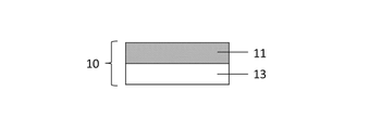
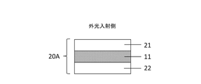
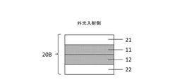
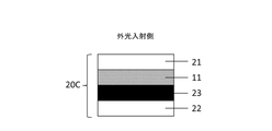
- FIG. 2 shows a diagram of forming a cholesteric liquid crystal layer according to the present invention on a plastic substrate. Examples of embodiments of the optical layered body of the present invention are shown. Other examples of aspects of the optical layered body of the present invention are shown. Other examples of aspects of the optical layered body of the present invention are shown. Other examples of aspects of the optical layered body of the present invention are shown. Other examples of aspects of the optical layered body of the present invention are shown.
- FIG. 1 shows a conceptual diagram of an apparatus for measuring the angular dependence of the reflected hue of the optical layered body of the present invention. 1 shows reflection spectra of cholesteric liquid crystal layers (or optical laminates) produced in Example 1 and Comparative Examples 1 and 2.
- FIG. 4 shows reflection spectra of cholesteric liquid crystal layers (or optical laminates) produced in Examples 2 to 5.
- FIG. 1 shows a conceptual diagram of an apparatus for measuring the angular dependence of the reflected hue of the optical layered body of the present invention. 1 shows reflection spectra
- the optical layered body according to the present embodiment (hereinafter also referred to as “the optical layered body of the present invention”) includes a support, a cholesteric liquid crystal layer (hereinafter also referred to as a light reflecting layer), and optionally a polarizing element and a It has one support. These are described in order below.
- the cholesteric liquid crystal used in the present invention is composed of a nematic liquid crystal having chirality or a compound obtained by adding a chiral agent to the nematic liquid crystal.
- a cholesteric liquid crystal obtained by adding a chiral agent to a nematic liquid crystal is preferred because the direction of the helix or the reflection wavelength can be arbitrarily designed by the type or amount of the chiral agent.
- the nematic liquid crystal used in the present invention is preferably a nematic liquid crystal monomer having a polymerizable group because the nematic liquid crystal used in the present invention is used with its helically aligned state fixed, unlike the so-called liquid crystal operated by an electric field.
- a nematic liquid crystal monomer having a polymerizable group is a compound that has a polymerizable group in its molecule and exhibits liquid crystallinity within a specific temperature range or concentration range.
- polymerizable groups include (meth)acryloyl groups, vinyl groups, chalconyl groups, cinnamoyl groups, and epoxy groups.
- Liquid crystal compounds with rod-shaped or platelet-shaped substituents are known in the art as calamitic liquid crystals.
- Nematic liquid crystal monomers having such polymerizable groups are specifically polymerizable liquid crystals described in JP-A-2003-315556 and JP-A-2004-29824, PALIOCOLOR series (manufactured by BASF), RMM series. (manufactured by Merck) and the like. These nematic liquid crystal monomers having a polymerizable group can be used alone or in combination.
- the nematic liquid crystal monomer having the polymerizable group can be helically aligned to the right-handed (R-configuration) or left-handed (L-configuration).
- Compounds are preferred.
- Examples of such a chiral agent include Paliocolor LC756 (manufactured by BASF) and compounds described in JP-A-2002-179668.
- the direction of reflected circularly polarized light is determined by the type of chiral agent, and the reflection wavelength of the cholesteric liquid crystal layer can be changed according to the amount of the chiral agent added to the nematic liquid crystal.
- the amount of the chiral agent to be added varies depending on the type of chiral agent and the wavelength to be reflected. It is preferably 0.5 to 30 parts by weight, more preferably 1 to 20 parts by weight, still more preferably 3 to 10 parts by weight.
- a polymerizable compound having no liquid crystallinity and capable of reacting with a nematic liquid crystal monomer having a polymerizable group examples include polymerizable compounds that form ultraviolet curable resins.
- UV-curable resins include dipentaerythritol hexa(meth)acrylate, a reaction product of dipentaerythritol penta(meth)acrylate and 1,6-hexamethylene diisocyanate, triisocyanate having an isocyanuric ring and pentaerythritol tri( Reaction products with meth)acrylates, reaction products of pentaerythritol tri(meth)acrylate and isophorone diisocyanate, dipentaerythritol penta(meth)acrylate, dipentaerythritol tetra(meth)acrylate, pentaerythritol tetra(meth)acrylate , pentaerythritol tri(meth)acrylate, trimethylolpropane tri(meth)acrylate, ditrimethylolpropane tetra(meth)acrylate, tris(acryloxyethyl)iso
- polymerizable compounds having no liquid crystallinity must be added to such an extent that the nematic liquid crystal monomer having a polymerizable group does not lose liquid crystallinity. 0.1 to 20 parts by weight, more preferably 1.0 to 10 parts by weight.
- a photopolymerization initiator is added to cure the composition containing them with UV rays.
- photopolymerization initiators include 2-methyl-1-[4-(methylthio)phenyl]-2-morpholinopropane-1,1-hydroxycyclohexylphenyl ketone, 4-(2-hydroxyethoxy)-phenyl(2- Hydroxy-2-propyl)ketone, 1-(4-dodecylphenyl)-2-hydroxy-2-methylpropan-1-one, 1-(4-isopropylphenyl)-2-hydroxy-2-methylpropane-1- Acetophenone-based compounds such as on, 2-hydroxy-2-methyl-1-phenylpropan-1-one, diethoxyacetophenone, benzoin, benzoin methyl ether, benzoin ethyl ether, benzoin isopropyl ether
- auxiliaries are triethanolamine, methyldiethanolamine, triisopropanolamine, n-butylamine, N-methyldiethanolamine, diethylaminoethyl methacrylate, Michler's ketone, 4,4'-diethylaminophenone, 4-dimethylaminobenzoic acid.
- auxiliaries include amine compounds such as ethyl, (n-butoxy)ethyl 4-dimethylaminobenzoate, and isoamyl 4-dimethylaminobenzoate.
- the amount of the photopolymerization initiator and auxiliary agent added is preferably within a range that does not affect the liquid crystallinity of the composition containing the nematic liquid crystal monomer used in the present invention. It is preferably from 0.5 to 10 parts by weight, more preferably from 2 to 8 parts by weight, per 100 parts by weight of the compound that cures at 100 parts by weight. Also, the amount of the auxiliary agent is preferably 0.5 to 2 times the amount of the photopolymerization initiator.
- the composition further contains a solvent.
- a solvent is not particularly limited as long as it can dissolve the liquid crystal compound, chiral agent, and the like to be used. , is cyclopentanone with good solubility. Moreover, these solvents can be added in an arbitrary ratio, and only one type may be added, or a plurality of solvents may be used in combination. These solvents are removed by drying in a drying oven or drying equipment of a film coating apparatus.
- a nematic liquid crystal monomer having a polymerizable group is added with a right-handed or left-handed chiral agent so as to reflect a desired wavelength. Add required amount. Next, these are dissolved in a solvent and a photopolymerization initiator is added. After that, this solution is applied on a plastic substrate such as a polyethylene terephthalate (PET) film so that the thickness is as uniform as possible. The coating film is allowed to stand for a certain period of time under temperature conditions such that the pitch is oriented.
- PET polyethylene terephthalate
- the orientation of the cholesteric liquid crystal can be made more uniform, and the haze value of each cholesteric liquid crystal layer can be reduced. becomes.
- ultraviolet light is irradiated with a high pressure mercury lamp or the like to fix the orientation, thereby changing the silver color used in the present invention.
- the desired reflection band can be obtained by adjusting the oxygen concentration in the atmosphere in which the ultraviolet rays are irradiated, the irradiation amount of the ultraviolet rays, the irradiation time, the irradiation temperature, and the like.
- the reflection band should be at least about 380 nm to 850 nm, preferably 380 nm to 900 nm, more preferably 380 nm to 1000 nm.
- the film thickness of the cholesteric liquid crystal layer after film formation is preferably 1 ⁇ m to 15 ⁇ m, more preferably 2 ⁇ m to 10 ⁇ m.
- the structure of the cholesteric liquid crystal layer of the optical layered body depends on the design of the eyewear. may be provided, or if the polarization property is not important, only the light reflecting layer of either the cholesteric liquid crystal layer R body or the cholesteric liquid crystal layer L body may be provided. Moreover, these configurations are not particularly limited as long as they exhibit the effects of the present invention, and any of them can be used.
- the reflectance of the cholesteric liquid crystal layer of the present invention depends on the design of the eyewear, but the average reflectance in the visible light region (380 nm to 780 nm) is preferably at least 10%, more preferably 20% or more. more preferred. This makes it possible to impart a surface that is bright and has a mirror-like metallic luster. Note that the reflectance may be measured in the form of the optical layered body described later.
- the reflection characteristic since the reflection characteristic has angle dependence, it reflects substantially uniformly over the wavelength range of the visible light region and the near infrared region (wavelength 781 nm or more). It is preferable to have a ratio.
- the angle dependence is caused by the complex layered structure of the cholesteric liquid crystal layer due to the relationship between the angle of the light incident on the cholesteric liquid crystal layer and the angle of the light reflected by it, and as a result, the entire reflected waveform is short wavelength. It is known to be a phenomenon of shifting to the side. Therefore, the wavy structure in the long wavelength region shifted by this shift causes coloring. Therefore, by having the same reflection property in the near infrared region, the property shifts to the visible light region as it is, so that it can function as a light reflection layer with little coloring.
- the average reflectance (hereinafter referred to as R1) in the wavelength range of 500 nm to 700 nm and at least the average reflectance (hereinafter referred to as R2) in the wavelength range of 701 nm to 900 nm of the cholesteric liquid crystal layer The absolute value of the difference ( ⁇ R1-R2) (also represented as
- the cholesteric liquid crystal layer has a reflection characteristic in the near-infrared region. It cannot be colored.
- the number of spiral pitches in the cholesteric liquid crystal layer should be the same for each wavelength band so that the selective reflectance is uniform. good. For this purpose, it is preferable to lengthen the alignment time of the cholesteric liquid crystal. How long the alignment time should be can be appropriately determined depending on how the temperature is applied and the type of chiral agent.
- the reflection characteristics of two wavelength ranges are compared relatively using their average values.
- the range is not limited, for example, R1 may be 500 nm to 699 nm, R2 may be 700 nm to 900 nm, R1 may be 499 nm to 700 nm, R2 may be 701 nm to 899 nm, and the measurement conditions of the spectrophotometer , for example, R1 may have a wavelength of 500 nm to 700 nm, and R2 may have a wavelength of 705 nm to 900 nm.
- the optical laminate according to the present invention preferably has a configuration in which only the cholesteric liquid crystal layer or a cholesteric liquid crystal layer and a polarizing element are sandwiched between supports, and either configuration can be appropriately adopted depending on the design and application of the eyewear.
- polarizing element examples include polyvinyl alcohol (PVA)-based polarizing films, coated polarizing films, etc. Typically, PVA-based polarizing films are preferably used. can.
- a known stretching method can be applied to the production method of the PVA-based polarizing film.
- a polymer film containing PVA or a derivative thereof is adsorbed with a dye such as iodine or a dichroic dye, and the film is uniaxially biaxially stretched. It is manufactured by stretching and orienting to about 5 times.
- dichroic dyes are preferable from the viewpoint of hue design and designability, and direct dyes containing azo dyes having a sulfonic acid group are more preferable from the viewpoint of heat resistance.
- a polarizing element in which a support is laminated or sandwiched between supports is referred to as a polarizing plate.
- dichroic dye for example, C.I. I. Direct Yellow 12, C.I. I. Direct Yellow 28, C.I. I. Direct Yellow 44, C.I. I. Direct Yellow 142, C.I. I. Direct Orange 26, C.I. I. Direct Orange 39, C.I. I. Direct Orange 71, C.I. I. Direct Orange 107, C.I. I. Direct Red 2, C.I. I. Direct Red 31, C.I. I. Direct Red 79, C.I. I. Direct Red 81, C.I. I. Direct Red 117, C.I. I. Direct Red 247, C.I. I. Direct Green 80, C.I. I. Direct Green 59, C.I. I. Direct Blue 71, C.I. I.
- Direct Blue 78 C.I. I. Direct Blue 168, C.I. I. Direct Blue 202, C.I. I. Direct Violet 9, C.I. I. Direct Violet 51, C.I. I. Direct Brown 106, C.I. I. Direct Brown 223 and the like can be mentioned, and these dyes may be used singly or in combination.
- the dichroic dye may be a dye that can be produced by a known method. Examples include the method described in the publication. Examples of commercially available dyes include Kayafect Violet P Liquid (manufactured by Nippon Kayaku Co., Ltd.), Kayafect Yellow Y and Kayafect Orange G, Kayafect Blue KW and Kayafect Blue Liquid 400.
- optical properties mainly visibility correction transmittance Ys and visibility correction polarization degree Py
- hue for example, values obtained from the CIE 1976 color space (L * , a * , b * )), etc. are designed.
- Examples of the polarizing element used in the present invention include optical characteristics such as a luminosity correction equal transmittance Ys of 10 to 60% and a luminosity correction degree of polarization of 60% or more, which does not affect the field of view of the eyewear wearer. From the point of view, it is preferable that the color has a neutral gray hue.
- examples of commercially available polarizing elements for polarized sunglasses containing a dichroic dye include Gray type manufactured by Nippon Kayaku Co., Ltd. made of a PVA resin film, NYSH-30 manufactured by Nippon Kayaku Co., Ltd. (each film The thickness is 25 to 35 ⁇ m), and these can be preferably applied as the polarizing element used in the present invention.
- the hue of the polarizing element may be a hue such as brown, depending on the design of the eyewear and the visibility of the field of view.
- the hue of transmission when worn as sunglasses for example, the relative luminosity attenuation rate Q value specified in JIS T7333 regarding the visibility of traffic lights, is within the standard. It is particularly preferable to appropriately adjust the types of dyes used in the polarizing element and, when multiple dyes are used, the compounding ratio thereof.
- the Q value is adjusted to be equal to or greater than the values shown below.
- the optical layered body of the present invention conforming to such traffic light visibility standards is particularly preferable as eyewear used when driving a car.
- the degree of polarization should be sufficient for sunglasses, preferably Py is 70% or more, more preferably 80% or more, and still more preferably 90% or more.
- optical laminate The configuration of the optical layered body of the present invention will be exemplified below, but the optical layered body of the present invention is not limited thereto.
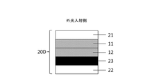
- One of the embodiments of the optical layered body is a first support/cholesteric liquid crystal layer R-body (or L-body)/second support.
- Another embodiment is a configuration of first support/cholesteric liquid crystal layer L body (or R body)/cholesteric liquid crystal layer R body (or L body)/second support.
- the optical laminate includes a polarizing element, for example, first support/cholesteric liquid crystal layer R body (or L body)/polarizing element/second support, first support/cholesteric liquid crystal layer L body (or R body)/cholesteric liquid crystal layer R body (or L body)/polarizing element/second support.
- a polarizing element for example, first support/cholesteric liquid crystal layer R body (or L body)/polarizing element/second support, first support/cholesteric liquid crystal layer L body (or R body)/cholesteric liquid crystal layer R body (or L body)/polarizing element/second support.
- a third support may be provided between the polarizing element and the cholesteric liquid crystal layer.
- the first support, the second support, and the third support may be made of the same material, or may be made of different materials depending on the design of the eyewear. good.
- each layer of the optical layered body is laminated via an adhesive layer.
- the film thickness of each support is 10 ⁇ m to 200 ⁇ m, preferably 40 ⁇ m to 100 ⁇ m.
- the cholesteric liquid crystal layer formed on a plastic substrate such as a PET film is adhered to a polarizing element or a support, then the substrate film is removed, and other layers are sequentially added. may be laminated to form the above embodiment.
- the support is a film- or sheet-like transparent resin material, and examples thereof include materials containing polycarbonate (PC)-based resins, triacetylcellulose (TAC)-based resins, polyamide (PA)-based resins, and the like.
- PC-based resins it is more preferable to use aromatic PC composed of bisphenol A.
- the total light transmittance of the support is preferably 70% or more, more preferably 80% or more, and even more preferably 85% or more, visibility can be easily ensured.
- an aromatic PCC composition whole alicyclic polyester composition
- PA resin having a glass transition temperature of 130° C. or less is selected. is preferred.
- PA-based resins have less optical anisotropy than PC-based resins, suppress birefringence, and have excellent solvent resistance. In addition, it has a low specific gravity, is lightweight, and has a low heat distortion temperature, so that it has good workability during molding.
- the same material is used for the injection molding resin of the lens substrate layer and the support of the optical laminate in order to prevent deterioration of the appearance due to the difference in refractive index and to ensure adhesion. It is preferable to use a PA-based resin also in that it is desirable to use a PA resin.
- the use of a PA-based resin is preferable in that there is no restriction on the material of the frame, since it is possible to suppress the whitening phenomenon of the frame due to the influence of outgassing due to heating.
- PA-based resins include nylon containing an aliphatic skeleton and aramid composed only of an aromatic skeleton.
- Nylon includes nylon 6, nylon 11, nylon 12, and nylon 66.
- Aramid includes para-aramid and meta-aramid.
- the PA-based resin used in the optical laminate of the present invention is preferably in the form of a transparent film or sheet, and for example, a commercially available nylon film (thickness: 80 ⁇ m) manufactured by EMS can be used.
- the adhesive layer is preferably optically colorless and transparent.
- UV-curing or thermosetting resins containing monomers or polymers such as vinyl chloride copolymers, modified polyolefins, epoxy-based, fluorine-based, natural rubber-based, and rubber-based rubbers such as synthetic rubbers can be appropriately selected and used.
- UV-curable adhesives including radical polymerization type and / or cationic polymerization type adhesives, especially solvent-free UV curable adhesives can be preferably used.
- the thickness of the adhesive layer can be appropriately determined according to the purpose of use, adhesive strength, etc., and is not particularly limited, but is generally 0.01 ⁇ m to 20 ⁇ m, preferably 5 ⁇ m to 15 ⁇ m. If the thickness of the adhesive layer is 5 ⁇ m or less, there is a risk of insufficient adhesion to the adherend, and if it exceeds 15 ⁇ m, optical distortion may occur in the product state.
- Each layer of the optical layered body may be subjected to surface modification using a commercially available treatment apparatus such as corona treatment or plasma treatment during the adhesion process or in a process prior to the adhesion process in order to improve adhesion. .
- the eyewear lens of the present invention can be obtained by molding the optical layered body of the present invention into a desired shape so that the light reflecting layer is on the outside. Furthermore, by fixing to a frame, the eyewear of the present invention such as sunglasses, goggles, and helmet visor can be obtained.
- An example of the process for forming a polarizing lens according to the present invention will be described below, but the present invention is not limited to this.
- sunglasses can be produced by punching out the optical laminate for eyewear of the present invention into a desired shape and then bending the punch.
- the method of bending There is no particular limitation on the method of bending, and the bending may be performed through a process that can impart a shape to a spherical or aspherical surface according to the purpose.
- shaping processing is performed in advance using a heat press machine or the like.
- a mold designed to have a predetermined size is used, and is appropriately designed according to the design of the eyewear product.
- the optical laminate is placed in a bending mold (concave mold) and pressed with a hemispherical mold (convex mold or hot iron ball) heated to a predetermined temperature to bend the optical laminate. be able to.
- the processing conditions for bending are, for example, considering the bendability and heat resistance of the optical laminate (discoloration of the polarizing element, etc.), the temperature is 70 to 120 ° C., preferably 80 to 100 ° C., and the time is 1 to 3 minutes. do it in range. Also, at this time, from the sheet-like optical layered body, only a part of the optical layered body to be used in the next insert molding step may be trimmed at the same time or sequentially.
- the bent product may be further injected with resin (also called lens base material).
- resin also called lens base material
- the resin to be injected it is preferable to use the same material as the layer with which the injected resin is in contact, in order to prevent deterioration of the appearance due to the difference in refractive index.
- the lens base material is a resin material used for integrating the optical laminate of the present invention and the resin and processing it into a lens shape.
- the integral processing can generally use an insert molding method.
- the lens base material is not particularly limited, and for example, thermoplastic resins that can be molded by injection molding, thermosetting resins that are commonly used for eyewear lenses, etc. that can be molded by chu-type polymerization or the like can be used. can be done.
- (meth)acrylic resins such as methyl methacrylate homopolymers, copolymers of methyl methacrylate and one or more other monomers; diethylene glycol bisallyl carbonate homopolymers, diethylene glycol bisallyl carbonate and one or more other Diethylene glycol bisallyl carbonate resins such as copolymers with monomers of, acrylonitrile-styrene copolymers, halogen-containing copolymers, homopolymers of monomers having sulfide bonds, monomers having sulfide bonds and one or more other Polysulfide resin, polyurea resin, PA resin, PC resin, polystyrene resin, polyolefin resin, polyvinyl chloride resin, polyester resin, PET resin, polyurethane resin, etc.
- the lens substrate is preferably made of the same material as the contacting layer.
- the support of the optical laminate on the side to be integrally processed is made of a PA-based resin
- the lens substrate is also made of a PA-based resin, so that the support and the lens substrate are fused together. can be done. This makes it possible to obtain a lens in which the optical layered body and the lens substrate are integrated.
- the lens obtained as described above is appropriately formed with a hard coat, an antireflection film, etc. on the surface thereof, and then fixed to a frame by beading, drilling, screwing, etc., to obtain the eyewear of the present invention. Obtainable.
- the reflectance of the light reflecting layer and the optical laminate can be measured according to JIS Z 8722:2009, and can be measured using, for example, a spectrophotometer U-4100 manufactured by Hitachi High-Tech Science.
- the reflection measurement is a total reflection measurement in which the surface of the light reflection layer is placed in the integrating sphere of the spectrophotometer. At that time, natural light is used as the light source, and the reflectance is measured by setting the measurement samples in the directions of 0 degree and 90 degrees, respectively, and the average value of the reflectances is taken.
- the reflectance detection condition for each wavelength is set to a pitch of 10 nm or less, preferably a pitch of 5 nm or less, more preferably a pitch of 1 nm. can reduce the difference between
- the angular dependence of the reflection hue of the light reflecting layer and the optical laminate can be quantitatively evaluated using, for example, a motorized goniometer (DMS series) manufactured by Konica Minolta.
- DMS series motorized goniometer
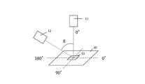
- the measurement is performed in the reflection mode, and as shown in FIG. 6, the reflected light from the reflecting surface of the sample 33 placed flat on the measurement stage 30 can be measured by the light receiving section of the device.
- the light-receiving part can be inclined at any angle (0 degrees (or represented by the symbol “°”) to 70 degrees) with respect to the sample surface.
- the inclination angle of 0 degree is taken to be perpendicular to the sample surface.
- the measurement stage 30 can be horizontally rotated in any direction (0 degrees to 359 degrees, where 0 degrees is the initial installation position of the sample 33).
- FIG. 6 shows the light receiving unit 31 of the measuring device installed at a position with an inclination angle of 0 degrees and the light receiving unit 32 of the measuring device when inclined at an angle ⁇ .
- the 0 degree or 180 degree orientation of the measurement stage 30 Since the reflectance value obtained by this measurement can be obtained as a dependence for each wavelength, a hue value based on the CIE 1976 color space (L * a * b * ) can be obtained.
- the hue change when the tilt angle is 10 degrees or more, preferably 30 degrees or more evaluation. For example, if the change in hue is small at a larger tilt angle, the effects of the present invention can be expected even in polarized lenses or eyewear with a large curve diameter.
- the hue change can be evaluated, for example, as the hue difference at each tilt angle with respect to the tilt angle of 0 degrees, and represented by
- the amount of change in the reflection hue of the light-reflecting layer is such that the observation position is 0 degrees in the direction perpendicular to the reflecting surface, and the observation position is tilted to 60 degrees.
- are preferably within the above ranges when the viewing position is tilted to 60 degrees.
- the calculation is performed in the wavelength range of 380 to 780 nm, where the spectral transmittance ⁇ at a predetermined wavelength interval d ⁇ (here, 5 nm) is used, P ⁇ is the spectral distribution of the standard light (C light source), y ⁇ is the 2-degree field of view, etc. represents a color function.
- the visibility correction transmittance Ys can be calculated using Ts.
- the visibility-corrected polarization degree Py can be obtained from equation (3).
- the degree of polarization can be measured, for example, using a spectrophotometer U-4100 manufactured by Hitachi High-Tech Science.
- the test sample is preferably placed so that the polarizing element side is the incident surface of the light source.
- the visibility correction polarization degree (Py) is preferably 75% or more and less than 100%, more preferably 90% or more and less than 100%.
- Py is in the above range, when the optical laminate is used as a lens, polarized sunglasses having a high antiglare effect against external light including reflected light can be obtained, which is preferable.
- Example 1 (Preparation of polarizing element)
- the polarizing element NYSH-30 manufactured by Nippon Kayaku Co., Ltd., which is a dye-based PVA-based resin film for polarized sunglasses, was used.
- the polarizing element exhibits a gray color, and when the polarization characteristics were measured using a spectrophotometer U-4100 manufactured by Hitachi High-Tech Science Co., Ltd., the visibility correction transmittance (Ys) was 38.0%, and the visibility correction The degree of polarization (Py) was 99.50%.
- the cholesteric liquid crystal layer was prepared by forming a cholesteric liquid crystal having a right-handed helical orientation on a rubbed PET film (A4100, film thickness: 50 ⁇ m) manufactured by Toyobo Co., Ltd. as a base material according to Example 1 of JP-A-2003-139953.
- a layer (cholesteric liquid crystal layer R body) was produced.
- the coating film from which the solvent was removed was held at 120° C. for 30 minutes as the alignment treatment time, thereby adding a treatment for aligning the cholesteric liquid crystal layer.
- the obtained cholesteric liquid crystal layer had a film thickness of about 4 ⁇ m.
- the sample was laid flat with the reflective surface facing upward and viewed from directly above (front direction), the sample exhibited a silver color.
- the polarizing element and a PC-based resin film (Teijin Panlite Film PC-2151, film thickness 125 ⁇ m) are laminated using the ultraviolet curable adhesive described in Example 1 of WO 2019/116760, A polarizing plate having a support on one side was obtained.
- the liquid crystal layer surface of the cholesteric liquid crystal layer R and a TAC resin film (13SG80S-LH manufactured by IPI Co., film thickness 80 ⁇ m) are laminated using an ultraviolet curable adhesive in the same manner as described above, and then the PET base material is laminated. was peeled off to obtain a cholesteric liquid crystal layer R having a support on one side.
- an optical device having a single liquid crystal layer shown in FIG. A laminate was produced.
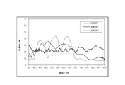
- the optical layered body was measured using U-4100 manufactured by Hitachi High-Tech Science Co., Ltd. under the detection condition of 1 nm pitch, and the reflection spectrum is shown in FIG. From this spectrum, the average reflectance at wavelengths of 380 nm to 780 nm was calculated to be 22.8%.
- the reflectance of the obtained optical laminate was measured using U-4100 manufactured by Hitachi High-Tech Science Co., Ltd. under the detection condition of 1 nm pitch, and the average reflectance (R1) at a wavelength of 500 nm to 700 nm was 22.4%. , and the average reflectance (R2) at wavelengths from 701 nm to 900 nm was 25.0%.
- the obtained optical layered body was shaped using a heat press.
- the optical laminate was placed in a bending mold (concave mold, 9 cm ⁇ ), and a hemispherical hot iron ball heated to 100°C was pressed for about 3 minutes to bend the reflective surface to the convex side. rice field.
- the degree of curvature of the obtained curved shape was measured with a curve meter (model number 340) manufactured by Sannishimura Co., Ltd., and the value was 8 curves.
- Example 1 was the same as in Example 1 except that the cholesteric liquid crystal layer was oriented for 5 minutes so as to obtain the reflection spectrum shown in FIG. At this time, the average reflectance at a wavelength of 380 nm to 780 nm is 24.7%, the average transmittance (R1) of the optical laminate at a wavelength of 500 nm to 700 nm is 29.0%, and the average transmittance at a wavelength of 701 nm to 900 nm ( R2) was 12.4%. Moreover, Py was 82.1%.
- a cholesteric liquid crystal layer having a maximum reflectance at a wavelength of 460 nm and a right-handed helical orientation (hereinafter referred to as , referred to as a light reflecting layer R460), a cholesteric liquid crystal layer having a maximum reflectance at a wavelength of 560 nm and a left-handed spiral alignment (hereinafter referred to as a light reflecting layer L560), and a right-handed spiral alignment having a maximum reflectance at a wavelength of 640 nm.
- the PET substrate on the light reflecting layer L560 side of this laminate was peeled off, and this liquid crystal surface and the liquid crystal layer surface of the light reflecting layer R460 were similarly laminated using an ultraviolet curable adhesive.
- the PET base material on the light reflecting layer R640 side of this laminate is peeled off, and the liquid crystal layer surface and the polarizing element surface of the polarizing plate are similarly laminated using an ultraviolet curable adhesive to obtain three layers.
- An optical laminate having a liquid crystal layer of The reflected hue of the optical layered body viewed from the front was silver.
- the optical layered body was measured using U-4100 manufactured by Hitachi High-Tech Science Co., Ltd. under the detection condition of 1 nm pitch, and the reflection spectrum is shown in FIG. From this spectrum, the average reflectance at wavelengths of 380 nm to 780 nm was calculated to be 24.4%. Moreover, Py was 75.4%.
- Example 1 The description of Example 1 is the same except for the preparation of the cholesteric liquid crystal layer and the optical laminate.
- Table 1 shows the evaluation results of the cholesteric liquid crystal layers and optical laminates prepared in Example 1 and Comparative Examples 1 and 2.
- the reflectance is substantially uniform over the wavelength of 380 nm to 900 nm. It was as small as .6. Further, as shown in Table 2, even when the change in the reflected hue in the oblique direction of the optical layered body is tilted by 60 degrees, both
- the reflectance is not substantially uniform over the wavelength of 380 nm to 900 nm, and the difference (
- the reflectance was not substantially uniform over the wavelength of 380 nm to 900 nm, and the difference (
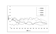
- Example 2 The description of Example 1 is the same as that of Example 1 except that the film thickness of the coating film after curing was adjusted to about 3 ⁇ m to produce a cholesteric liquid crystal layer R body so as to obtain the reflection spectrum shown in FIG.
- the average reflectance at a wavelength of 380 nm to 780 nm is 17.1%
- the average transmittance (R1) of the optical laminate at a wavelength of 500 nm to 700 nm is 16.1%
- the average transmittance at a wavelength of 701 nm to 900 nm ( R2) was 15.4%.
- Py was 96.7%.
- Example 3 The description of Example 1 is the same as that of Example 1 except that the film thickness of the coating film after curing was adjusted to about 2 ⁇ m to produce a cholesteric liquid crystal layer R body so that the reflection spectrum shown in FIG. 8 was obtained.
- the average reflectance at a wavelength of 380 nm to 780 nm is 10.4%
- the average transmittance (R1) of the optical laminate at a wavelength of 500 nm to 700 nm is 10.9%
- the average transmittance at a wavelength of 701 nm to 900 nm ( R2) was 9.6%.
- Py was 97.0%.
- Example 4 The description of Example 1 is the same as that of Example 1 except that the film thickness of the coating film after curing was adjusted to about 6 ⁇ m to produce a cholesteric liquid crystal layer R body so as to obtain the reflection spectrum shown in FIG.
- the average reflectance at a wavelength of 380 nm to 780 nm is 28.9%
- the average transmittance (R1) of the optical laminate at a wavelength of 500 nm to 700 nm is 29.3%
- the average transmittance at a wavelength of 701 nm to 900 nm ( R2) was 23.1%.
- Py was 79.6%.
- Example 5 The description of Example 1 is the same as that of Example 1 except that the film thickness of the coating film after curing was adjusted to about 5 ⁇ m to prepare the cholesteric liquid crystal layer R body so as to obtain the reflection spectrum shown in FIG.
- the average reflectance at a wavelength of 380 nm to 780 nm is 25.9%
- the average transmittance (R1) of the optical laminate at a wavelength of 500 nm to 700 nm is 26.5%
- the average transmittance at a wavelength of 701 nm to 900 nm ( R2) was 24.7%.
- Py was 84.2%.
- the optical laminate of the present invention can change the Py depending on the average reflectance at wavelengths of 380 nm to 780 nm.
- Example 3 when the average reflectance was 10.4%, the Py was 97.0%, which was the highest value, and the polarization characteristics of the single polarizing element could be maintained.
- Example 4 the average reflectance was 28.9%, which was a high reflection characteristic, but the Py was 79.6%, and the polarization characteristic was degraded.
- Example 5 shows an average reflectance at a wavelength of 380 nm to 780 nm equivalent to Comparative Examples 1 and 2, but shows higher Py than these Comparative Examples. It was possible to obtain an optical layered body having optical properties superior to those of the conventional structure.
- the light reflecting layer is made of an organic material, it is possible to obtain an achromatic silver reflecting surface that is not colored when viewed from any angle.
- eyewear comprising an optical layered body containing a polarizing element, when the reflectance of the light reflecting layer of the eyewear is emphasized while maintaining the effects of the present invention, when the degree of polarization as polarized sunglasses is emphasized, these The optical design of eyewear can be realized in a wider range, such as when considering the balance of
Landscapes
- Physics & Mathematics (AREA)
- Health & Medical Sciences (AREA)
- Ophthalmology & Optometry (AREA)
- General Physics & Mathematics (AREA)
- Optics & Photonics (AREA)
- General Health & Medical Sciences (AREA)
- Nonlinear Science (AREA)
- Chemical & Material Sciences (AREA)
- Crystallography & Structural Chemistry (AREA)
- Polarising Elements (AREA)
- Eyeglasses (AREA)
Priority Applications (4)
| Application Number | Priority Date | Filing Date | Title |
|---|---|---|---|
| JP2023507194A JPWO2022196784A1 (cg-RX-API-DMAC7.html) | 2021-03-18 | 2022-03-17 | |
| US18/280,816 US20240160049A1 (en) | 2021-03-18 | 2022-03-17 | Optcal laminate and eyewear using same |
| CN202280019236.2A CN116917782A (zh) | 2021-03-18 | 2022-03-17 | 光学层叠体、使用了其的眼镜 |
| EP22771529.9A EP4310559A4 (en) | 2021-03-18 | 2022-03-17 | Optcal laminate and eyewear using same |
Applications Claiming Priority (2)
| Application Number | Priority Date | Filing Date | Title |
|---|---|---|---|
| JP2021-045239 | 2021-03-18 | ||
| JP2021045239 | 2021-03-18 |
Publications (1)
| Publication Number | Publication Date |
|---|---|
| WO2022196784A1 true WO2022196784A1 (ja) | 2022-09-22 |
Family
ID=83320444
Family Applications (1)
| Application Number | Title | Priority Date | Filing Date |
|---|---|---|---|
| PCT/JP2022/012464 Ceased WO2022196784A1 (ja) | 2021-03-18 | 2022-03-17 | 光学積層体、それを用いたアイウェア |
Country Status (6)
| Country | Link |
|---|---|
| US (1) | US20240160049A1 (cg-RX-API-DMAC7.html) |
| EP (1) | EP4310559A4 (cg-RX-API-DMAC7.html) |
| JP (1) | JPWO2022196784A1 (cg-RX-API-DMAC7.html) |
| CN (1) | CN116917782A (cg-RX-API-DMAC7.html) |
| TW (1) | TWI907667B (cg-RX-API-DMAC7.html) |
| WO (1) | WO2022196784A1 (cg-RX-API-DMAC7.html) |
Cited By (1)
| Publication number | Priority date | Publication date | Assignee | Title |
|---|---|---|---|---|
| WO2025164622A1 (ja) * | 2024-01-29 | 2025-08-07 | 日本化薬株式会社 | 光学積層体、偏光レンズ及びアイウェア |
Citations (12)
| Publication number | Priority date | Publication date | Assignee | Title |
|---|---|---|---|---|
| JPS59145255A (ja) | 1983-02-07 | 1984-08-20 | Nippon Kayaku Co Ltd | 水溶性ジスアゾ化合物 |
| JPH0312606A (ja) | 1989-06-12 | 1991-01-21 | Nippon Kayaku Co Ltd | 水溶性アゾ染料及びこれを含有する偏光膜 |
| JP2002179668A (ja) | 2000-12-15 | 2002-06-26 | Fuji Photo Film Co Ltd | 光学活性化合物、液晶キラル剤、液晶組成物、液晶カラーフィルター、光学フイルム及び記録媒体 |
| JP2003139953A (ja) | 2001-11-05 | 2003-05-14 | Nitto Denko Corp | 光学素子の製造方法、光学素子、光学フィルム並びにこれらを用いた照明装置及び液晶表示装置 |
| JP2003315556A (ja) | 2002-02-19 | 2003-11-06 | Nitto Denko Corp | 光学補償機能付き偏光板、及びそれを用いた液晶表示装置 |
| JP2004029824A (ja) | 2002-06-27 | 2004-01-29 | Merck Patent Gmbh | ポリマー化液晶材料を含む膜の製造方法 |
| WO2016002582A1 (ja) | 2014-07-01 | 2016-01-07 | 日本化薬株式会社 | 光学フィルムおよびこれを用いた光学積層体 |
| WO2017175581A1 (ja) | 2016-04-07 | 2017-10-12 | 日本化薬株式会社 | 光反射フィルム、ならびにこれを用いた光制御フィルムおよびミラーディスプレイ |
| WO2018159297A1 (ja) * | 2017-02-28 | 2018-09-07 | 日本ゼオン株式会社 | 光学異方性積層体、円偏光板、及び画像表示装置 |
| WO2019116760A1 (ja) | 2017-12-13 | 2019-06-20 | 株式会社ポラテクノ | 光学積層体、これを備えた偏光レンズ及びアイウェア |
| JP2020076972A (ja) * | 2018-10-12 | 2020-05-21 | 日本化薬株式会社 | 偏光発光板、及びそれを備えた光学装置 |
| WO2020235413A1 (ja) * | 2019-05-17 | 2020-11-26 | 株式会社ポラテクノ | 光学素子又は偏光板及びこれらを用いたアイウェア |
Family Cites Families (5)
| Publication number | Priority date | Publication date | Assignee | Title |
|---|---|---|---|---|
| KR101446379B1 (ko) * | 2011-05-06 | 2014-10-01 | 엘지디스플레이 주식회사 | 영상표시장치 |
| CN105093649B (zh) * | 2015-08-14 | 2019-04-30 | 深圳市华星光电技术有限公司 | 防蓝光偏光板及液晶显示面板 |
| JP6840733B2 (ja) * | 2016-04-08 | 2021-03-10 | 日本化薬株式会社 | アイウェア用光学フィルム、並びにこれを用いた光学積層体およびアイウェア |
| EP3457195A1 (en) * | 2017-09-19 | 2019-03-20 | Hoya Lens Thailand Ltd. | Spectacle lenses and methods for producing the same |
| EP3982174B1 (en) * | 2019-03-28 | 2025-09-03 | Nippon Kayaku Kabushiki Kaisha | Optical film and eyewear |
-
2022
- 2022-03-17 JP JP2023507194A patent/JPWO2022196784A1/ja active Pending
- 2022-03-17 US US18/280,816 patent/US20240160049A1/en active Pending
- 2022-03-17 CN CN202280019236.2A patent/CN116917782A/zh active Pending
- 2022-03-17 WO PCT/JP2022/012464 patent/WO2022196784A1/ja not_active Ceased
- 2022-03-17 EP EP22771529.9A patent/EP4310559A4/en active Pending
- 2022-03-18 TW TW111110165A patent/TWI907667B/zh active
Patent Citations (12)
| Publication number | Priority date | Publication date | Assignee | Title |
|---|---|---|---|---|
| JPS59145255A (ja) | 1983-02-07 | 1984-08-20 | Nippon Kayaku Co Ltd | 水溶性ジスアゾ化合物 |
| JPH0312606A (ja) | 1989-06-12 | 1991-01-21 | Nippon Kayaku Co Ltd | 水溶性アゾ染料及びこれを含有する偏光膜 |
| JP2002179668A (ja) | 2000-12-15 | 2002-06-26 | Fuji Photo Film Co Ltd | 光学活性化合物、液晶キラル剤、液晶組成物、液晶カラーフィルター、光学フイルム及び記録媒体 |
| JP2003139953A (ja) | 2001-11-05 | 2003-05-14 | Nitto Denko Corp | 光学素子の製造方法、光学素子、光学フィルム並びにこれらを用いた照明装置及び液晶表示装置 |
| JP2003315556A (ja) | 2002-02-19 | 2003-11-06 | Nitto Denko Corp | 光学補償機能付き偏光板、及びそれを用いた液晶表示装置 |
| JP2004029824A (ja) | 2002-06-27 | 2004-01-29 | Merck Patent Gmbh | ポリマー化液晶材料を含む膜の製造方法 |
| WO2016002582A1 (ja) | 2014-07-01 | 2016-01-07 | 日本化薬株式会社 | 光学フィルムおよびこれを用いた光学積層体 |
| WO2017175581A1 (ja) | 2016-04-07 | 2017-10-12 | 日本化薬株式会社 | 光反射フィルム、ならびにこれを用いた光制御フィルムおよびミラーディスプレイ |
| WO2018159297A1 (ja) * | 2017-02-28 | 2018-09-07 | 日本ゼオン株式会社 | 光学異方性積層体、円偏光板、及び画像表示装置 |
| WO2019116760A1 (ja) | 2017-12-13 | 2019-06-20 | 株式会社ポラテクノ | 光学積層体、これを備えた偏光レンズ及びアイウェア |
| JP2020076972A (ja) * | 2018-10-12 | 2020-05-21 | 日本化薬株式会社 | 偏光発光板、及びそれを備えた光学装置 |
| WO2020235413A1 (ja) * | 2019-05-17 | 2020-11-26 | 株式会社ポラテクノ | 光学素子又は偏光板及びこれらを用いたアイウェア |
Non-Patent Citations (2)
| Title |
|---|
| JOURNAL OF JAPANESE LIQUID CRYSTAL SOCIETY, vol. 2, 25 April 1998 (1998-04-25) |
| See also references of EP4310559A4 |
Cited By (1)
| Publication number | Priority date | Publication date | Assignee | Title |
|---|---|---|---|---|
| WO2025164622A1 (ja) * | 2024-01-29 | 2025-08-07 | 日本化薬株式会社 | 光学積層体、偏光レンズ及びアイウェア |
Also Published As
| Publication number | Publication date |
|---|---|
| JPWO2022196784A1 (cg-RX-API-DMAC7.html) | 2022-09-22 |
| EP4310559A4 (en) | 2025-03-12 |
| EP4310559A1 (en) | 2024-01-24 |
| TW202244247A (zh) | 2022-11-16 |
| TWI907667B (zh) | 2025-12-11 |
| US20240160049A1 (en) | 2024-05-16 |
| CN116917782A (zh) | 2023-10-20 |
Similar Documents
| Publication | Publication Date | Title |
|---|---|---|
| US10866435B2 (en) | Optical film for eyewear with light control, light reflection, and polarization layers | |
| US10120206B2 (en) | Optical film and optical laminate using same | |
| US10942374B2 (en) | Optical film for eyewear, and optical laminate and eyewear using the optical film | |
| TW201902705A (zh) | 附有遮光功能之眼用器具用光學膜,及使用該光學膜之光學積層體,以及附有遮光功能之眼用器具 | |
| US20240160049A1 (en) | Optcal laminate and eyewear using same | |
| TW202208159A (zh) | 多層光反射膜及具備該反射膜之眼用配戴物 | |
| TWI907668B (zh) | 光學積層體 | |
| TWI869580B (zh) | 光學膜、以及具備其之光學積層體及眼鏡 | |
| WO2025164622A1 (ja) | 光学積層体、偏光レンズ及びアイウェア | |
| CN221804330U (zh) | 光学层叠体、偏光透镜及眼用配戴品 |
Legal Events
| Date | Code | Title | Description |
|---|---|---|---|
| 121 | Ep: the epo has been informed by wipo that ep was designated in this application |
Ref document number: 22771529 Country of ref document: EP Kind code of ref document: A1 |
|
| ENP | Entry into the national phase |
Ref document number: 2023507194 Country of ref document: JP Kind code of ref document: A |
|
| WWE | Wipo information: entry into national phase |
Ref document number: 202280019236.2 Country of ref document: CN |
|
| WWE | Wipo information: entry into national phase |
Ref document number: 18280816 Country of ref document: US |
|
| WWE | Wipo information: entry into national phase |
Ref document number: 2022771529 Country of ref document: EP |
|
| NENP | Non-entry into the national phase |
Ref country code: DE |
|
| ENP | Entry into the national phase |
Ref document number: 2022771529 Country of ref document: EP Effective date: 20231018 |