WO2022196658A1 - 樹脂製容器の製造方法および製造装置 - Google Patents
樹脂製容器の製造方法および製造装置 Download PDFInfo
- Publication number
- WO2022196658A1 WO2022196658A1 PCT/JP2022/011443 JP2022011443W WO2022196658A1 WO 2022196658 A1 WO2022196658 A1 WO 2022196658A1 JP 2022011443 W JP2022011443 W JP 2022011443W WO 2022196658 A1 WO2022196658 A1 WO 2022196658A1
- Authority
- WO
- WIPO (PCT)
- Prior art keywords
- container
- mold
- preform
- injection molding
- injection
- Prior art date
- Legal status (The legal status is an assumption and is not a legal conclusion. Google has not performed a legal analysis and makes no representation as to the accuracy of the status listed.)
- Ceased
Links
Images




Classifications
-
- B—PERFORMING OPERATIONS; TRANSPORTING
- B29—WORKING OF PLASTICS; WORKING OF SUBSTANCES IN A PLASTIC STATE IN GENERAL
- B29C—SHAPING OR JOINING OF PLASTICS; SHAPING OF MATERIAL IN A PLASTIC STATE, NOT OTHERWISE PROVIDED FOR; AFTER-TREATMENT OF THE SHAPED PRODUCTS, e.g. REPAIRING
- B29C49/00—Blow-moulding, i.e. blowing a preform or parison to a desired shape within a mould; Apparatus therefor
- B29C49/28—Blow-moulding apparatus
- B29C49/30—Blow-moulding apparatus having movable moulds or mould parts
-
- B—PERFORMING OPERATIONS; TRANSPORTING
- B29—WORKING OF PLASTICS; WORKING OF SUBSTANCES IN A PLASTIC STATE IN GENERAL
- B29B—PREPARATION OR PRETREATMENT OF THE MATERIAL TO BE SHAPED; MAKING GRANULES OR PREFORMS; RECOVERY OF PLASTICS OR OTHER CONSTITUENTS OF WASTE MATERIAL CONTAINING PLASTICS
- B29B11/00—Making preforms
- B29B11/06—Making preforms by moulding the material
- B29B11/08—Injection moulding
-
- B—PERFORMING OPERATIONS; TRANSPORTING
- B29—WORKING OF PLASTICS; WORKING OF SUBSTANCES IN A PLASTIC STATE IN GENERAL
- B29B—PREPARATION OR PRETREATMENT OF THE MATERIAL TO BE SHAPED; MAKING GRANULES OR PREFORMS; RECOVERY OF PLASTICS OR OTHER CONSTITUENTS OF WASTE MATERIAL CONTAINING PLASTICS
- B29B11/00—Making preforms
- B29B11/14—Making preforms characterised by structure or composition
- B29B11/16—Making preforms characterised by structure or composition comprising fillers or reinforcement
-
- B—PERFORMING OPERATIONS; TRANSPORTING
- B29—WORKING OF PLASTICS; WORKING OF SUBSTANCES IN A PLASTIC STATE IN GENERAL
- B29C—SHAPING OR JOINING OF PLASTICS; SHAPING OF MATERIAL IN A PLASTIC STATE, NOT OTHERWISE PROVIDED FOR; AFTER-TREATMENT OF THE SHAPED PRODUCTS, e.g. REPAIRING
- B29C33/00—Moulds or cores; Details thereof or accessories therefor
- B29C33/42—Moulds or cores; Details thereof or accessories therefor characterised by the shape of the moulding surface, e.g. ribs or grooves
-
- B—PERFORMING OPERATIONS; TRANSPORTING
- B29—WORKING OF PLASTICS; WORKING OF SUBSTANCES IN A PLASTIC STATE IN GENERAL
- B29C—SHAPING OR JOINING OF PLASTICS; SHAPING OF MATERIAL IN A PLASTIC STATE, NOT OTHERWISE PROVIDED FOR; AFTER-TREATMENT OF THE SHAPED PRODUCTS, e.g. REPAIRING
- B29C45/00—Injection moulding, i.e. forcing the required volume of moulding material through a nozzle into a closed mould; Apparatus therefor
- B29C45/16—Making multilayered or multicoloured articles
-
- B—PERFORMING OPERATIONS; TRANSPORTING
- B29—WORKING OF PLASTICS; WORKING OF SUBSTANCES IN A PLASTIC STATE IN GENERAL
- B29C—SHAPING OR JOINING OF PLASTICS; SHAPING OF MATERIAL IN A PLASTIC STATE, NOT OTHERWISE PROVIDED FOR; AFTER-TREATMENT OF THE SHAPED PRODUCTS, e.g. REPAIRING
- B29C45/00—Injection moulding, i.e. forcing the required volume of moulding material through a nozzle into a closed mould; Apparatus therefor
- B29C45/17—Component parts, details or accessories; Auxiliary operations
- B29C45/26—Moulds
-
- B—PERFORMING OPERATIONS; TRANSPORTING
- B29—WORKING OF PLASTICS; WORKING OF SUBSTANCES IN A PLASTIC STATE IN GENERAL
- B29C—SHAPING OR JOINING OF PLASTICS; SHAPING OF MATERIAL IN A PLASTIC STATE, NOT OTHERWISE PROVIDED FOR; AFTER-TREATMENT OF THE SHAPED PRODUCTS, e.g. REPAIRING
- B29C49/00—Blow-moulding, i.e. blowing a preform or parison to a desired shape within a mould; Apparatus therefor
- B29C49/02—Combined blow-moulding and manufacture of the preform or the parison
- B29C49/06—Injection blow-moulding
-
- B—PERFORMING OPERATIONS; TRANSPORTING
- B29—WORKING OF PLASTICS; WORKING OF SUBSTANCES IN A PLASTIC STATE IN GENERAL
- B29C—SHAPING OR JOINING OF PLASTICS; SHAPING OF MATERIAL IN A PLASTIC STATE, NOT OTHERWISE PROVIDED FOR; AFTER-TREATMENT OF THE SHAPED PRODUCTS, e.g. REPAIRING
- B29C49/00—Blow-moulding, i.e. blowing a preform or parison to a desired shape within a mould; Apparatus therefor
- B29C49/02—Combined blow-moulding and manufacture of the preform or the parison
- B29C49/06—Injection blow-moulding
- B29C49/061—Injection blow-moulding with parison holding means displaceable between injection and blow stations
- B29C49/062—Injection blow-moulding with parison holding means displaceable between injection and blow stations following an arcuate path, e.g. rotary or oscillating-type
-
- B—PERFORMING OPERATIONS; TRANSPORTING
- B29—WORKING OF PLASTICS; WORKING OF SUBSTANCES IN A PLASTIC STATE IN GENERAL
- B29C—SHAPING OR JOINING OF PLASTICS; SHAPING OF MATERIAL IN A PLASTIC STATE, NOT OTHERWISE PROVIDED FOR; AFTER-TREATMENT OF THE SHAPED PRODUCTS, e.g. REPAIRING
- B29C49/00—Blow-moulding, i.e. blowing a preform or parison to a desired shape within a mould; Apparatus therefor
- B29C49/22—Blow-moulding, i.e. blowing a preform or parison to a desired shape within a mould; Apparatus therefor using multilayered preforms or parisons
-
- B—PERFORMING OPERATIONS; TRANSPORTING
- B29—WORKING OF PLASTICS; WORKING OF SUBSTANCES IN A PLASTIC STATE IN GENERAL
- B29C—SHAPING OR JOINING OF PLASTICS; SHAPING OF MATERIAL IN A PLASTIC STATE, NOT OTHERWISE PROVIDED FOR; AFTER-TREATMENT OF THE SHAPED PRODUCTS, e.g. REPAIRING
- B29C49/00—Blow-moulding, i.e. blowing a preform or parison to a desired shape within a mould; Apparatus therefor
- B29C49/42—Component parts, details or accessories; Auxiliary operations
- B29C49/42412—Marking or printing
-
- B—PERFORMING OPERATIONS; TRANSPORTING
- B65—CONVEYING; PACKING; STORING; HANDLING THIN OR FILAMENTARY MATERIAL
- B65D—CONTAINERS FOR STORAGE OR TRANSPORT OF ARTICLES OR MATERIALS, e.g. BAGS, BARRELS, BOTTLES, BOXES, CANS, CARTONS, CRATES, DRUMS, JARS, TANKS, HOPPERS, FORWARDING CONTAINERS; ACCESSORIES, CLOSURES, OR FITTINGS THEREFOR; PACKAGING ELEMENTS; PACKAGES
- B65D1/00—Rigid or semi-rigid containers having bodies formed in one piece, e.g. by casting metallic material, by moulding plastics, by blowing vitreous material, by throwing ceramic material, by moulding pulped fibrous material or by deep-drawing operations performed on sheet material
-
- B—PERFORMING OPERATIONS; TRANSPORTING
- B29—WORKING OF PLASTICS; WORKING OF SUBSTANCES IN A PLASTIC STATE IN GENERAL
- B29C—SHAPING OR JOINING OF PLASTICS; SHAPING OF MATERIAL IN A PLASTIC STATE, NOT OTHERWISE PROVIDED FOR; AFTER-TREATMENT OF THE SHAPED PRODUCTS, e.g. REPAIRING
- B29C49/00—Blow-moulding, i.e. blowing a preform or parison to a desired shape within a mould; Apparatus therefor
- B29C49/02—Combined blow-moulding and manufacture of the preform or the parison
- B29C2049/023—Combined blow-moulding and manufacture of the preform or the parison using inherent heat of the preform, i.e. 1 step blow moulding
-
- B—PERFORMING OPERATIONS; TRANSPORTING
- B29—WORKING OF PLASTICS; WORKING OF SUBSTANCES IN A PLASTIC STATE IN GENERAL
- B29C—SHAPING OR JOINING OF PLASTICS; SHAPING OF MATERIAL IN A PLASTIC STATE, NOT OTHERWISE PROVIDED FOR; AFTER-TREATMENT OF THE SHAPED PRODUCTS, e.g. REPAIRING
- B29C49/00—Blow-moulding, i.e. blowing a preform or parison to a desired shape within a mould; Apparatus therefor
- B29C49/08—Biaxial stretching during blow-moulding
- B29C49/10—Biaxial stretching during blow-moulding using mechanical means for prestretching
- B29C49/12—Stretching rods
Definitions
- the present invention relates to a method and apparatus for manufacturing resin containers.
- Containers that hold cosmetics, milky lotions, etc. are required to have an appearance that is aesthetically pleasing in order to increase consumer willingness to purchase.
- a container for storing cosmetics of this kind a glass bottle is preferably used because it has a solid feeling and a high-class feeling, and can keep a beautiful state even after repeated use.
- glass bottles are heavy, fragile, and expensive to transport and manufacture. Therefore, it is being studied to replace glass bottles with resin containers for containers for storing cosmetics and the like.
- a hot parison blow molding method has been conventionally known as one of the methods for manufacturing resin containers.
- a resin container is blow molded using the heat retained during injection molding of a preform.
- the injection-molded preform is blow-molded without being removed from the machine. It is also easy to make adjustments. Therefore, compared with the cold parison type, it is advantageous in that it is possible to manufacture a variety of resin containers with excellent aesthetic appearance.
- the resin container When a resin container is used as a container for storing cosmetics, etc., the resin container is formed into a shape with a thick bottom and a thin and even-walled body in order to emphasize the sense of luxury and weight. is desirable.
- a preform with a thick bottom and a large amount of heat retained at the bottom is blow-molded.
- a method for manufacturing a resin container which is one aspect of the present invention, includes a first injection molding step of injection-molding a bottomed cylindrical resin intermediate molded body, injection molding a resin material on the intermediate molded body, and performing intermediate molding.
- a second injection molding step for manufacturing a multilayer preform in which a resin layer is laminated on a body a blow molding step for manufacturing a resin container by blow molding the multilayer preform in a state of having the heat retained at the time of injection molding, including.
- the multilayer preform is formed thicker at the bottom than at the body.
- at least one surface of the bottom of the multilayer preform is pressed with a mold to transfer a three-dimensional pattern corresponding to the mold to the thick bottom of the resin container.
- a three-dimensional pattern can be accurately formed on the thick bottom of a resin container.
- FIG. BRIEF DESCRIPTION OF THE DRAWINGS It is a figure which shows typically the structure of the blow molding apparatus of 1st Embodiment. It is a figure which shows the example of a manufacturing process of the preform of 1st Embodiment. It is a figure which shows the blow molding process of 1st Embodiment. It is a flowchart which shows the process of the manufacturing method of a container.
- FIG. BRIEF DESCRIPTION OF THE DRAWINGS It is a figure which shows typically the structure of the blow molding apparatus of 1st Embodiment. It is a figure which shows the example of a manufacturing process of the preform of 1st Embodiment. It is a figure which shows the blow molding process of 1st Embodiment. It is a flowchart which shows the process of the manufacturing method of a container.
- FIG. 11 is a perspective view of a container of a second embodiment; (a) is a front view of the container of 2nd Embodiment, (b) is a longitudinal cross-sectional view of the container of Fig.9 (a). It is a figure which shows the blow molding process of 2nd Embodiment.
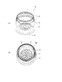
- FIGS. 1 and 2 are perspective views of the container 10 of the first embodiment.
- 1(a) and 1(b) are perspective views of the container 10 of the first embodiment.
- 2(a) is a front view of the container 10 of the first embodiment
- FIG. 2(b) is a longitudinal sectional view of the container 10 of FIG. 2(a).
- the container 10 shown in FIGS. 1 and 2 has a short cylindrical shape as a whole and has an opening on the upper surface side.
- the container 10 is made of, for example, a resin material such as PET, and contains lotion, milky lotion, and the like.
- the container 10 has a neck portion 12 having a mouth portion 11 at its upper end, a short tubular body portion 13 continuing from the neck portion 12 , and a bottom portion 14 continuing from the body portion 13 .
- the thickness t2 of the bottom portion 14 of the container 10 is formed to be greater than the thickness t1 of the body portion 13. That is, the thickness t1 of the body portion 13 is formed considerably thinner than that of the bottom portion 14, and the thickness of the body portion 13 is made uniform.
- the thickness t2 of the bottom portion 14 of the container 10 is set to 6 mm or more (6 mm to 15 mm), preferably, for example, 10 mm or more (10 mm to 15 mm).
- the container 10 By forming the container 10 into a shape having the thickness distribution described above, the feeling of luxury and weight is emphasized, and the container 10 can be brought closer to the consumer's image of a cosmetic container. That is, since the aesthetic appearance of the container 10 can be enhanced, the container 10 can be used as a cosmetic container or the like in which appearance is important.
- the body portion 13 and the bottom portion 14 of the container 10 have a structure in which a first layer 15 facing the inner surface of the container and a second layer 16 facing the outer surface of the container are laminated. there is This structure is formed by blow molding a preform 20 to be described later.
- a three-dimensional pattern 17 is applied to the inner surface side of the bottom portion 14 of the container 10 .
- the three-dimensional pattern 17 is a depression that is concave downward from the container inner surface of the bottom portion 14 toward the inside of the bottom portion 14, and is formed in, for example, a diamond shape (polyhedron group shape) or corolla shape.
- the diamond-shaped or corolla-shaped three-dimensional pattern 17 shown in FIGS. It also has a function of enhancing the high-class feeling of the container 10 by producing scattering.
- the shape of the three-dimensional pattern 17 is not limited to the examples shown in FIGS. 1 and 2, and can be changed as appropriate.
- FIG. 3 is a longitudinal sectional view of a preform (multilayer preform, two-layer preform) 20 applied to manufacture the container 10 of the first embodiment.
- the overall shape of the preform 20 is a bottomed cylindrical shape with an opening at one end and a closed end at the other end.
- the preform 20 includes a cylindrical body 23, a bottom 24 closing the other end of the body 23, and a neck 22 formed at one end of the body 23 and having a mouth 21.
- the preform 20 shown in FIG. 3 has a body portion 23 whose length in the axial direction is set short so as to correspond to the short cylindrical container 10 .
- the preform 20 has a structure in which a first layer 15 located on the inner peripheral side and a second layer 16 located on the outer peripheral side are laminated.
- the neck portion 22 is made of the material of the first layer 15
- the body portion 23 and the bottom portion 24 are made of the second layer 16 laminated on the outer circumference of the first layer 15 .
- the preform 20 in FIG. 3 is formed as follows. First, an intermediate molded body 20A having a neck portion 22, a body portion 23 and a bottom portion 24 is injection molded with the material of the first layer 15. As shown in FIG. After that, the preform 20 is formed by further injection-molding the material of the second layer 16 around the outer periphery of the body portion 23 and the bottom portion 24 of the intermediate molded body 20A.
- compositions of the materials of the first layer 15 and the second layer 16 may be the same or different.
- the same resin material may be used for the first layer 15 and the second layer 16, or different materials may be used.
- the amount of coloring material (shade of color) or the type of coloring material (type of color) may be changed for each material of the first layer 15 and the second layer 16 .
- At least one of the first layer 15 and the second layer 16 (preferably both the first layer 15 and the second layer 16) has a property of transmitting light (light transmissivity or transparency). good.
- a preform 20 in which the thickness t12 of the bottom portion 24 is twice or more the thickness t11 of the body portion 23 is applied in order to shape the container 10 with a thick bottom.
- the dimensions and specifications of the preform 20, for example, the thicknesses of the first layer 15 and the second layer 16, can be appropriately changed according to the shape of the container 10 to be manufactured.
- the axial length of the entire preform 20 (the length from the upper end of the neck portion 22 to the lower end of the second layer 16 of the bottom portion 24) is preferably set longer than the container 10.
- the gate portion extending downward from the bottom portion 24 may be removed before blow molding.
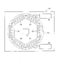
- FIG. 4 is a diagram schematically showing the configuration of the blow molding device 30 of the first embodiment.
- the blow molding apparatus 30 of the first embodiment is an example of a container manufacturing apparatus, and blow-molds a container by utilizing the heat (internal heat) during injection molding without cooling the preform 20 to room temperature.
- a hot parison method also called a one-stage method is adopted.
- the blow molding apparatus 30 includes a first injection molding section 31, a first temperature adjustment section 32, a second injection molding section 33, a second temperature adjustment section 34, a blow molding section 35, a take-out section 36, a conveying and a mechanism 37 .
- the first injection molding section 31, the first temperature adjustment section 32, the second injection molding section 33, the second temperature adjustment section 34, the blow molding section 35, and the ejection section 36 are arranged at a predetermined angle (for example, 60 degrees) with the transport mechanism 37 as the center. ) are rotated by increments.
- the blow molding device 30 may be configured without the first temperature control section 32 .
- the transport mechanism 37 includes a transport plate 37a that moves so as to rotate about an axis perpendicular to the plane of FIG.
- One or more neck molds 37b (not shown in FIG. 1) for holding the neck 22 of the preform 20 (or the neck 12 of the container 10) are arranged on the transfer plate 37a at predetermined angles.
- the transport mechanism 37 moves the preform 20 (or container 10) with the neck portion 22 held by the neck mold 37b to the first injection molding section 31 and the first temperature adjustment section. 32, the second injection molding section 33, the second temperature adjustment section 34, the blow molding section 35, and the removal section 36 in this order.
- the transport mechanism 37 moves the transfer plate 37a by 72 degrees to move the preform 20 (or container 10) to the first injection molding section 31. , the second injection molding section 33, the second temperature adjustment section 34, the blow molding section 35, and the removal section 36 in this order.
- the conveying mechanism 37 further includes an elevating mechanism (vertical mold opening/closing mechanism) and a mold opening mechanism for the neck mold 37b. Mold release) is also performed.
- the first injection molding section 31 includes an injection cavity mold 40 , an injection core mold 41 and a hot runner mold 42 and manufactures an intermediate molded product 20A of the preform 20 . As shown in FIG. 4 , the first injection molding unit 31 is connected to a first injection device 38 that supplies a resin material (first resin material) forming the first layer 15 to the hot runner mold 42 .
- FIG. 5(a) shows the injection molding process in the first injection molding section 31.
- the mold space for the first layer 15 is formed by closing the injection cavity mold 40, the injection core mold 41, and the neck mold 37b of the transport mechanism 37.
- an intermediate molded body (single part) corresponding to the first layer 15 in the first injection molding part 31 is formed.
- Layer preform) 20A is manufactured.
- the first resin material is a thermoplastic synthetic resin, and can be appropriately selected according to the specifications of the container 10.
- Specific types of materials include, for example, PET (polyethylene terephthalate), PEN (polyethylene naphthalate), PCTA (polycyclohexanedimethylene terephthalate), Tritan (Tritan (registered trademark): copolyester manufactured by Eastman Chemical Co.).
- PP polypropylene
- PE polyethylene
- PC polycarbonate
- PES polyethersulfone
- PPSU polyphenylsulfone
- PS polystyrene
- COP/COC cyclic olefin polymer
- PMMA polymethacrylic acid methyl: acryl
- PLA polylactic acid
- an additive such as a coloring agent may be added to the first resin material.
- PET polymethacrylic acid methyl: acryl
- PLA polylactic acid
- the neck mold 37b of the transport mechanism 37 is not opened and the intermediate molded body 20A is held and transported as it is.
- the number of intermediate molded bodies 20A molded simultaneously in the first injection molding section 31 (that is, the number of containers 10 that can be molded simultaneously in the blow molding device 30) can be appropriately set.
- the first temperature adjustment unit 32 includes a temperature adjustment mold (not shown) (heating pot or temperature adjustment pot (temperature adjustment pot) for adjusting the temperature of the intermediate molded body 20A from the outside, and a heating pot for adjusting the temperature of the preform 20 from the inside. rod, temperature control rod (temperature control rod) or air introduction rod).
- the first temperature control unit 32 cools (or heats) the intermediate molded body 20A in a high temperature state after injection molding by placing it in a temperature control mold maintained at a predetermined temperature.
- the first temperature adjustment section 32 also functions to adjust the temperature distribution of the intermediate molded body 20 ⁇ /b>A to a predetermined state before being transported to the second injection molding section 33 .
- the second injection molding section 33 includes an injection cavity mold 50 , an injection core mold 51 and a hot runner mold 52 , and injection molds the second layer 16 on the outer periphery of the first layer 15 . As shown in FIG. 4 , the second injection molding unit 33 is connected to a second injection device 39 that supplies the resin material (second resin material) forming the second layer 16 to the hot runner mold 52 .
- FIG. 5(b) shows the injection molding process in the second injection molding part 33.
- the injection cavity mold 50 of the second injection molding section 33 accommodates the intermediate molded body 20A injection-molded in the first injection molding section 31 .
- a mold space is formed between the inner surface of the injection cavity mold 50 and the intermediate molded body 20A, which is the first layer 15, from the body portion on the outer peripheral side to the bottom portion.
- the second layer 16 is molded around the outer periphery of the intermediate molded body 20A, which is the first layer 15. .
- the second layer 16 is laminated on the outer peripheral side of the first layer 15, and the preform (multilayer preform, two-layer preform) 20 shown in FIG. 3 is manufactured.
- the second resin material is a thermoplastic synthetic resin, and the specific material type is the same as the description for the first resin material.
- the composition of the second resin material may be the same as or different from that of the first resin material.
- the same resin material may be used for the first layer 15 and the second layer 16, or different materials may be used.
- the amount of coloring material, the type of coloring material, and the like may be changed for each material of the first layer 15 and the second layer 16 .
- PET it is not particularly limited, it is preferable to use PET as the second resin material in consideration of its translucency and low material cost.
- the second temperature control unit 34 includes a temperature control mold (not shown) (a heating pot or a temperature control pot (temperature control pot) for controlling the temperature of the preform 20 from the outside, and a heating rod for controlling the temperature of the preform 20 from the inside. , temperature control rod (temperature control rod) or air introduction rod).
- the second temperature control unit 34 equalizes or removes temperature variations in the preform 20 injection-molded by the temperature control mold, and adjusts the temperature of the preform 20 to a temperature suitable for blow molding (for example, about 90° C. to 105° C.) and the temperature distribution is adjusted to suit the shape of the container to be formed.
- the second temperature control unit 34 also has a function of cooling the preform 20 in a high temperature state after injection molding.
- the blow molding section 35 performs blow molding on the preform 20 whose temperature has been adjusted by the second temperature adjustment section 34 to manufacture the container 10 .
- FIG. 6 shows the blow molding process in the blow molding section 35.
- the blow molding section 35 includes a blow cavity mold 60 , a bottom mold 61 , an extension rod 62 and an air introducing member (blow core) 63 .
- the blow cavity mold 60 is a pair of split molds that define the shape of the container 10 excluding the bottom surface.
- the blow cavity mold 60 is divided by a parting surface (not shown) along the vertical direction in FIG. 6 and configured to be openable and closable in the horizontal direction in FIG.
- the bottom mold 61 is a mold material that is arranged below the blow cavity mold 60 and defines the shape of the bottom surface of the container 10 .
- a mold space that defines the shape of the container 10 is formed by closing the blow cavity mold 60 and the bottom mold 61 .
- the stretching rod 62 and the air introduction member (blow core) 63 are configured to be axially movable with respect to the neck mold 37b that holds the preform 20 .
- the stretch rods 62 press against the bottom 24 of the preform 20 from the inside to provide longitudinal stretching of the preform 20 as required.
- a pressing piece 64 having a convex portion with a shape corresponding to the three-dimensional pattern 17 and transferring the shape of the three-dimensional pattern 17 to the bottom 14 of the container 10 is attached.
- the outer diameter of the pressing piece 64 is set smaller than the inner diameter of the mouth portion 21 (or body portion 23 or bottom portion 24 ) of the preform 20 .
- the outer diameter of the pressing piece 64 should be adjusted to the mouth portion 21 (or body portion) of the preform 20. It is preferably two-thirds or more and four-fifths or less of the inner diameter of the portion 23 or the bottom portion 24).
- the diameter of the pressing piece 64 is set to the diameter of the air introducing member (blow core) 63 It is preferably set smaller than the inner diameter of the
- the air introduction member 63 is in close contact with the inner periphery of the neck portion 22 of the preform 20 in a state of being inserted into the neck mold 37b, and maintains airtightness with the preform 20 (or container 10). Also, the air introduction member 63 introduces blow air supplied from a compressor (not shown) into the preform 20 during blow molding.
- the preform 20 is housed in a mold space formed by the blow cavity mold 60 and the bottom mold 61.
- blow air is introduced into the preform 20 from the air introducing member 63 while the preform 20 is being stretched by the stretching rod 62 .
- the blow molding section 35 can manufacture the container 10 by shaping the preform 20 into the shape of the mold space.
- the shape of the three-dimensional pattern 17 is transferred to the inner surface of the bottom portion 14 of the container 10 by the pressing piece 64 of the extension rod 62 .
- the length of the container 10 is substantially the same as or shorter than the length of the preform 20 (when the preform has a longitudinal axis draw ratio of 0.8 to 1.2 (particularly 0.8 to 1.2). 9 to 1.1)).
- either the downward motion of the pressing piece 64 or the upward motion of the bottom mold 61 may be faster. That is, either the pressing piece 64 or the bottom mold 61 may come into contact with the preform 20 first.
- the bottom 24 of the preform 20 is sandwiched between the bottom mold 61 and the pressing piece 64 and pressed, the three-dimensional pattern is transferred to the bottom inner surface (or the bottom outer surface as described later) of the container 20 .
- the take-out part 36 is configured to release the neck part 12 of the container 10 manufactured by the blow molding part 35 from the neck mold 37 b and take out the container 10 to the outside of the blow molding device 30 .
- FIG. 7 is a flow chart showing the steps of the container manufacturing method.
- Step S101 First injection molding step
- the first injection molding section 31 injects a resin material from the first injection device 38 into the mold space of the intermediate molded body 20A formed by the injection cavity mold 40, the injection core mold 41 and the neck mold 37b of the conveying mechanism 37.
- an intermediate molded body 20A corresponding to the first layer 15 of the preform 20 is manufactured, as shown in FIG. 5(a).
- the first injection molding part 31 is opened and the intermediate molding 20A is released from the injection cavity mold 40 and the injection core mold 41.
- the transfer plate 37a of the transfer mechanism 37 is rotated by a predetermined angle.
- the intermediate molded body 20A held by the neck mold 37b is conveyed to the first temperature control section 32 while containing the heat retained during injection molding.
- the intermediate molded body 20A is exposed to air while being transported from the first injection molding section 31 to the first temperature control section 32 .
- the intermediate molded body 20A is slightly cooled from the outer surface, and heat exchange (heat conduction ) advances temperature uniformity.
- Step S102 first temperature adjustment step
- the intermediate molded body 20A is accommodated in the temperature control mold, and the first layer 11 is cooled and the temperature distribution is adjusted (temperature equalization and temperature deviation removal).
- the temperature of the intermediate molded body 20A is uniformed by heat exchange (heat conduction) between the skin layer and the core layer. Note that the first temperature adjustment step may be omitted.
- the transfer plate 37a of the transfer mechanism 37 is moved to rotate by a predetermined angle, and the temperature-adjusted intermediate molded body 20A held by the neck mold 37b is It is conveyed to the second injection molding section 33 . Since the intermediate molded body 20A is exposed to air while being transported from the first temperature control section 32 to the second injection molding section 33, the intermediate molded body 20A is slightly cooled from the outer surface and heat is exchanged between the skin layer and the core layer. Uniform temperature progresses due to (heat conduction).
- Step S103 Second injection molding step
- the resin material is injected from the second injection device 39 between the outer periphery of the intermediate molded body 20A and the injection cavity mold 50. is injected.
- the second layer 16 is formed on the outer peripheral portion of the intermediate molded body 20A, and the preform 20 is manufactured.
- the second injection molding part 33 is opened and the preform 20 is released from the injection cavity mold 50 and the injection core mold 51 .
- the transfer plate 37a of the transfer mechanism 37 is rotated by a predetermined angle.
- the preform 20 held by the neck mold 37b is conveyed to the second temperature control section 34 while containing the heat generated during injection molding.
- Step S104 second temperature adjustment step
- the preform 20 is accommodated in a temperature control mold, and temperature control is performed to bring the temperature of the preform 20 closer to a temperature suitable for final blowing.
- the transfer plate 37 a of the transfer mechanism 37 is rotated by a predetermined angle, and the temperature-adjusted preform 20 held by the neck mold 37 b is transferred to the blow molding section 35 .
- Step S105 blow molding step
- the blow molding of the container 10 is performed in the blow molding section 35 .
- the blow cavity mold 60 is closed to accommodate the preform 20 in the mold space, and the air introduction member 63 is lowered so that the neck portion 22 of the preform 20 is brought into contact with the air introduction member 63 .
- the stretching rod 62 is lowered to hold the bottom portion 24 of the preform 20 from the inner surface, and longitudinal stretching is performed as necessary (FIG. 6(a)).
- the preform 20 is laterally stretched by supplying blow air from the air introduction member 63 (FIG. 6(b)).
- the preform 20 is expanded and shaped so as to be in close contact with the mold space of the blow cavity mold 60 , and is blow-molded into the container 10 .
- the bottom mold 61 is kept on standby at a lower position where it does not come into contact with the bottom 24 of the preform 20 before the blow cavity mold 60 is closed, and is quickly raised to the molding position after the mold is closed. You can let it run.
- the shape of the three-dimensional pattern 17 is transferred to the inner surface of the bottom 14 of the container 10 by contacting the pressing piece 64 of the stretching rod 62 with the bottom 24 of the preform 20 .
- the bottom mold 61 may be brought into contact with the preform 20 and then the stretching rod 62 may be lowered to press the pressing piece 64 against the preform 20 .
- Step S106 container take-out step
- the blow cavity mold 60 and the bottom mold 61 are opened. This allows the container 10 to be moved from the blow molding section 35 . Subsequently, the transfer plate 37 a of the transfer mechanism 37 is rotated by a predetermined angle, and the container 10 is transferred to the pick-up section 36 . At the ejection section 36 , the neck 12 of the container 10 is released from the neck mold 37 b and the container 10 is ejected to the outside of the blow molding device 30 .
- the first injection molding process, the second injection molding process, the temperature adjustment process, the blow molding process, and the container removal process each have the same length of time.
- the transportation time between each process is also the same length.
- a preform 20 having a thick bottom portion 24 is manufactured in two injection molding steps in order to blow mold a thick-walled container 10 suitable for a cosmetic container or the like. Then, in the blow molding process, the three-dimensional pattern 17 is formed on the inner surface of the bottom portion 14 of the container 10 by the pressing piece 64 of the extension rod 62 .
- preforms retain more heat in proportion to their thickness, so the thicker the part, the easier it is to deform the preform. Therefore, when a preform having a thick portion is molded by one injection molding and a three-dimensional pattern is transferred to the thick portion, when the thick portion is stretched by blow molding, the thick portion may be It is easy for the inner surface of the thick part to become uneven because the thickness cannot be maintained. Furthermore, since the thick portion is likely to suffer from insufficient cooling, molding defects such as sink marks, air bubbles, and whitening (crystallization) may occur in the three-dimensional pattern (or the thick portion on which the three-dimensional pattern is formed).
- the maximum thickness of the preform that can suppress defects such as whitening is limited to about 9 mm. Therefore, when a container is molded from the preform, the preform is stretched to some extent (at least in the horizontal direction), so that the thickness of the bottom of the container is at most equal to or less than the above maximum thickness. It becomes a numerical value (for example, about 5 mm).
- the preform 20 is injection-molded in two steps as described above, and the second layer 16 is laminated on the intermediate molded body 20A that is exposed to air and temperature-controlled during transportation.
- the preform 20 of the first embodiment can reduce internal internal heat even though the bottom portion 24 is thicker than a preform manufactured in a single injection molding process. . Therefore, it becomes easy to adjust the amount of deformation of the thick bottom portion 24 in the blow molding process, and the three-dimensional pattern 17 can be accurately formed on the bottom portion 14 of the container 10 .
- the thick bottom of the container (specifically, the central region of the bottom) is partially recessed and thinned by the length of the three-dimensional pattern of the pressing piece 64 . Since the distance from the bottom mold surface to the inside (core layer) of the central area of the thick bottom, which has the most retained heat and is the most difficult to cool during blow molding, is reduced, the cooling efficiency of the bottom of the container can be improved. whitening of the bottom of the can be easily suppressed.
- the preform injected in the first injection molding process and the second injection molding process is thinner than when a thick preform is molded in one injection molding process. Difficulty in is also reduced.
- parameters such as cooling time for each injection molding step can be adjusted separately. Therefore, in the first embodiment, the thick preform 20 suitable for the specifications of the container 10 can be easily molded, so that the quality of the container 10 can be improved.
- the bottom thickness of the preform is formed to 16 mm while suppressing whitening.
- the bottom of the container can be easily formed to a thickness of about 10 mm (except for the portion where the three-dimensional pattern is formed).
- the injection/cooling time of each of the first injection molding process and the second injection molding process Both times are shorter.
- the injection/cooling time of the preform which is the rate-limiting step, is shortened, so that it is possible to shorten the molding cycle when manufacturing the thick-walled container 10 suitable for a cosmetic container or the like.
- the preform 20 is manufactured by two injection molding processes, the first layer 15 and the second layer 16 of the preform 20 can be colored differently. By imparting the three-dimensional pattern 17 to the container 10, the design of the container 10 can be further enhanced.
- a three-dimensional pattern 17A which is an example of a three-dimensional pattern, is applied to the outer surface side of the bottom portion 14 of the container 10A.
- the three-dimensional pattern 17A is a depression that is concave upward from the container outer surface of the bottom portion 14 toward the inside of the bottom portion 14, and is formed in a shape that imitates the appearance of a mountain, for example.
- Other configurations of the container 10A are the same as those of the first embodiment.
- FIG. 10 shows the blow molding process in the blow molding section 35 in the second embodiment.
- a convex portion 65 having a shape corresponding to the three-dimensional pattern 17A is formed on the upper surface of the bottom mold 61 facing the preform 20 .
- a tip piece 64a having a flat tip is attached to the tip of the extension rod 62 shown in FIG. Unlike the pressing piece 64, the tip piece 64a does not transfer the shape of the three-dimensional pattern. However, if it is desired to add a three-dimensional pattern to the inner surface of the bottom portion 14 as well, a pressing piece 64 for transferring the shape of the three-dimensional pattern may be attached to the extension rod 62 .
- the preform 20 When the blow air from the air introduction member 63 is introduced into the preform 20, the preform 20 is expanded and shaped so as to adhere to the mold space of the blow cavity mold 60, and is blow-molded into the container 10A.
- the convex portion 65 of the bottom mold 61 transfers the shape of the three-dimensional pattern 17A to the outer surface of the bottom portion 14 of the container 10A.
- a three-dimensional pattern may be formed on both the inner surface side and the outer surface side of the thick bottom portion of the container.
- the preform may be manufactured by laminating the second layer inside the first layer in the second injection molding step.
- a thin film portion is formed at the center of the bottom portion of the intermediate molded body by pressing with a pin or the like.
- the resin may be introduced into the intermediate molded body by injecting the resin to break the thin film portion.
Landscapes
- Engineering & Computer Science (AREA)
- Mechanical Engineering (AREA)
- Manufacturing & Machinery (AREA)
- Ceramic Engineering (AREA)
- Blow-Moulding Or Thermoforming Of Plastics Or The Like (AREA)
- Moulds For Moulding Plastics Or The Like (AREA)
- Injection Moulding Of Plastics Or The Like (AREA)
Priority Applications (3)
| Application Number | Priority Date | Filing Date | Title |
|---|---|---|---|
| US18/281,657 US20240131774A1 (en) | 2021-03-14 | 2022-03-13 | Resin container manufacturing method and manufacturing apparatus |
| CN202280034444.XA CN117295600A (zh) | 2021-03-15 | 2022-03-14 | 树脂制容器的制造方法以及制造装置 |
| JP2023507117A JP7566133B2 (ja) | 2021-03-15 | 2022-03-14 | 樹脂製容器の製造方法および製造装置 |
Applications Claiming Priority (2)
| Application Number | Priority Date | Filing Date | Title |
|---|---|---|---|
| JP2021-041526 | 2021-03-14 | ||
| JP2021041526 | 2021-03-15 |
Publications (1)
| Publication Number | Publication Date |
|---|---|
| WO2022196658A1 true WO2022196658A1 (ja) | 2022-09-22 |
Family
ID=83322324
Family Applications (1)
| Application Number | Title | Priority Date | Filing Date |
|---|---|---|---|
| PCT/JP2022/011443 Ceased WO2022196658A1 (ja) | 2021-03-14 | 2022-03-14 | 樹脂製容器の製造方法および製造装置 |
Country Status (4)
| Country | Link |
|---|---|
| US (1) | US20240131774A1 (https=) |
| JP (1) | JP7566133B2 (https=) |
| CN (1) | CN117295600A (https=) |
| WO (1) | WO2022196658A1 (https=) |
Citations (5)
| Publication number | Priority date | Publication date | Assignee | Title |
|---|---|---|---|---|
| JPS4925182B1 (https=) * | 1971-12-25 | 1974-06-28 | ||
| JPS56166027A (en) * | 1980-05-28 | 1981-12-19 | Katashi Aoki | Forming method for vessel in polyethylene terephthalate |
| JPH05169521A (ja) * | 1991-12-19 | 1993-07-09 | Sekisui Chem Co Ltd | 中空成形品の製造方法 |
| JP2009012789A (ja) * | 2007-06-29 | 2009-01-22 | Yoshino Kogyosho Co Ltd | 広口容器と延伸ロッド |
| WO2013012067A1 (ja) * | 2011-07-20 | 2013-01-24 | 日精エー・エス・ビー機械株式会社 | プリフォームの温度調整装置及びプリフォームの温度調整方法、樹脂製容器及び樹脂製容器の製造方法 |
Family Cites Families (9)
| Publication number | Priority date | Publication date | Assignee | Title |
|---|---|---|---|---|
| PE24697A1 (es) * | 1995-03-29 | 1997-09-01 | Continental Pet Technologies | Envase presurizado para rellenar resistente al resquebrajamiento del bebedero, preforma y metodo para fabricarlos |
| AR002773A1 (es) * | 1995-07-07 | 1998-04-29 | Continental Pet Technologies | Metodo para el moldeado por inyeccion de un articulo plastico y aparato para llevarlo a cabo. |
| JP3666110B2 (ja) * | 1996-03-21 | 2005-06-29 | 株式会社青木固研究所 | 延伸ロッド |
| US5851471A (en) * | 1996-05-16 | 1998-12-22 | The Coca-Cola Company | Method for injection molding a multi-layer preform for use in blow molding a plastic bottle |
| US9694515B2 (en) * | 2002-10-30 | 2017-07-04 | Plastic Technologies, Inc. | Overmolded container having an inner foamed layer |
| US20050136201A1 (en) * | 2003-12-22 | 2005-06-23 | Pepsico, Inc. | Method of improving the environmental stretch crack resistance of RPET without solid stating |
| NZ561814A (en) * | 2005-03-15 | 2010-12-24 | Coca Cola Co | Overmolded containers and methods of manufacture and use thereof |
| US8741206B2 (en) * | 2009-12-17 | 2014-06-03 | Eastman Chemical Company | Method and apparatus for stretch blow molding a container |
| WO2020251035A1 (ja) | 2019-06-12 | 2020-12-17 | 日精エー・エス・ビー機械株式会社 | プリフォーム、樹脂製容器およびそれらの製造方法 |
-
2022
- 2022-03-13 US US18/281,657 patent/US20240131774A1/en active Pending
- 2022-03-14 CN CN202280034444.XA patent/CN117295600A/zh active Pending
- 2022-03-14 WO PCT/JP2022/011443 patent/WO2022196658A1/ja not_active Ceased
- 2022-03-14 JP JP2023507117A patent/JP7566133B2/ja active Active
Patent Citations (5)
| Publication number | Priority date | Publication date | Assignee | Title |
|---|---|---|---|---|
| JPS4925182B1 (https=) * | 1971-12-25 | 1974-06-28 | ||
| JPS56166027A (en) * | 1980-05-28 | 1981-12-19 | Katashi Aoki | Forming method for vessel in polyethylene terephthalate |
| JPH05169521A (ja) * | 1991-12-19 | 1993-07-09 | Sekisui Chem Co Ltd | 中空成形品の製造方法 |
| JP2009012789A (ja) * | 2007-06-29 | 2009-01-22 | Yoshino Kogyosho Co Ltd | 広口容器と延伸ロッド |
| WO2013012067A1 (ja) * | 2011-07-20 | 2013-01-24 | 日精エー・エス・ビー機械株式会社 | プリフォームの温度調整装置及びプリフォームの温度調整方法、樹脂製容器及び樹脂製容器の製造方法 |
Also Published As
| Publication number | Publication date |
|---|---|
| JP7566133B2 (ja) | 2024-10-11 |
| CN117295600A (zh) | 2023-12-26 |
| US20240131774A1 (en) | 2024-04-25 |
| JPWO2022196658A1 (https=) | 2022-09-22 |
Similar Documents
| Publication | Publication Date | Title |
|---|---|---|
| JP7457077B2 (ja) | 首曲がり容器の製造方法、温度調整用金型、ブロー成形装置およびブロー成形方法 | |
| JP7353471B2 (ja) | 剥離容器の製造方法および製造装置 | |
| WO2019146701A1 (ja) | 樹脂製の容器部品の製造方法、金型ユニットおよびそれを備えるブロー成形機 | |
| US12454091B2 (en) | Method and apparatus for producing resin container | |
| WO2022196658A1 (ja) | 樹脂製容器の製造方法および製造装置 | |
| CN114901453B (zh) | 树脂制容器的制造方法及制造装置 | |
| WO2022014540A1 (ja) | 樹脂製容器の製造方法および製造装置 | |
| US12605877B2 (en) | Manufacturing method, manufacturing apparatus, and mold unit for resin container | |
| EP4470751A1 (en) | Temperature regulating mold and method for producing resin container | |
| CN116761708B (zh) | 树脂制容器的制造方法以及制造装置 | |
| US12544955B2 (en) | Resin-made container manufacturing method, manufacturing device, and metal mold unit | |
| WO2023204262A1 (ja) | 樹脂製容器の製造方法および製造装置 | |
| WO2023157863A1 (ja) | 温度調整用金型、温度調整方法および樹脂製容器の製造装置 | |
| WO2022220270A1 (ja) | 樹脂製容器の製造方法および製造装置 |
Legal Events
| Date | Code | Title | Description |
|---|---|---|---|
| 121 | Ep: the epo has been informed by wipo that ep was designated in this application |
Ref document number: 22771403 Country of ref document: EP Kind code of ref document: A1 |
|
| WWE | Wipo information: entry into national phase |
Ref document number: 2023507117 Country of ref document: JP |
|
| NENP | Non-entry into the national phase |
Ref country code: DE |
|
| WWE | Wipo information: entry into national phase |
Ref document number: 202280034444.X Country of ref document: CN |
|
| WWE | Wipo information: entry into national phase |
Ref document number: 18281657 Country of ref document: US |
|
| 122 | Ep: pct application non-entry in european phase |
Ref document number: 22771403 Country of ref document: EP Kind code of ref document: A1 |