WO2022196504A1 - 美容機器、及び美容方法 - Google Patents
美容機器、及び美容方法 Download PDFInfo
- Publication number
- WO2022196504A1 WO2022196504A1 PCT/JP2022/010418 JP2022010418W WO2022196504A1 WO 2022196504 A1 WO2022196504 A1 WO 2022196504A1 JP 2022010418 W JP2022010418 W JP 2022010418W WO 2022196504 A1 WO2022196504 A1 WO 2022196504A1
- Authority
- WO
- WIPO (PCT)
- Prior art keywords
- cosmetic
- beauty device
- beauty
- temperature
- application
- Prior art date
- Legal status (The legal status is an assumption and is not a legal conclusion. Google has not performed a legal analysis and makes no representation as to the accuracy of the status listed.)
- Ceased
Links
Images



Classifications
-
- A—HUMAN NECESSITIES
- A45—HAND OR TRAVELLING ARTICLES
- A45D—HAIRDRESSING OR SHAVING EQUIPMENT; EQUIPMENT FOR COSMETICS OR COSMETIC TREATMENTS, e.g. FOR MANICURING OR PEDICURING
- A45D34/00—Containers or accessories specially adapted for handling liquid toiletry or cosmetic substances, e.g. perfumes
- A45D34/04—Appliances specially adapted for applying liquid, e.g. using roller or ball
-
- A—HUMAN NECESSITIES
- A61—MEDICAL OR VETERINARY SCIENCE; HYGIENE
- A61F—FILTERS IMPLANTABLE INTO BLOOD VESSELS; PROSTHESES; DEVICES PROVIDING PATENCY TO, OR PREVENTING COLLAPSING OF, TUBULAR STRUCTURES OF THE BODY, e.g. STENTS; ORTHOPAEDIC, NURSING OR CONTRACEPTIVE DEVICES; FOMENTATION; TREATMENT OR PROTECTION OF EYES OR EARS; BANDAGES, DRESSINGS OR ABSORBENT PADS; FIRST-AID KITS
- A61F7/00—Heating or cooling appliances for medical or therapeutic treatment of the human body
-
- A—HUMAN NECESSITIES
- A61—MEDICAL OR VETERINARY SCIENCE; HYGIENE
- A61K—PREPARATIONS FOR MEDICAL, DENTAL OR TOILETRY PURPOSES
- A61K8/00—Cosmetics or similar toiletry preparations
- A61K8/02—Cosmetics or similar toiletry preparations characterised by special physical form
-
- A—HUMAN NECESSITIES
- A61—MEDICAL OR VETERINARY SCIENCE; HYGIENE
- A61K—PREPARATIONS FOR MEDICAL, DENTAL OR TOILETRY PURPOSES
- A61K8/00—Cosmetics or similar toiletry preparations
- A61K8/18—Cosmetics or similar toiletry preparations characterised by the composition
- A61K8/30—Cosmetics or similar toiletry preparations characterised by the composition containing organic compounds
- A61K8/33—Cosmetics or similar toiletry preparations characterised by the composition containing organic compounds containing oxygen
- A61K8/34—Alcohols
-
- A—HUMAN NECESSITIES
- A61—MEDICAL OR VETERINARY SCIENCE; HYGIENE
- A61Q—SPECIFIC USE OF COSMETICS OR SIMILAR TOILETRY PREPARATIONS
- A61Q19/00—Preparations for care of the skin
Definitions
- the present disclosure relates to beauty equipment and beauty methods.
- Patent Literature 1 discloses a beauty device that supplies cosmetics in a steam state to the skin.
- the thermal effect does not last and decreases due to the heat of vaporization of the applied cosmetics.
- An object of the present invention is to provide a beauty device that can obtain a cosmetic effect without reducing the thermal effect.
- one aspect of the present disclosure is a beauty device having a contact surface that contacts a predetermined skin region, the heating unit being disposed on the contact surface and heating the skin region;
- a beauty device is provided, which is arranged on the contact surface and has an applicator for applying a cosmetic to the skin region, and a controller for controlling the amount of the cosmetic applied by the applicator.
- a cosmetic effect can be obtained without reducing the thermal effect.
- FIG. 3 is a block diagram showing the internal configuration of the beauty device (first embodiment) of FIG. 2.
- FIG. 7 is a cross-sectional view taken along line BB of FIG. 6;
- FIG. 7 is a block diagram showing the internal configuration of the beauty device (second embodiment) of FIG. 6;
- It is a flow chart of the beauty method concerning an embodiment. It is a figure which shows the timing chart of the heating process and application process in the beauty treatment method of embodiment.
- a three-dimensional orthogonal coordinate system with three axial directions (X direction, Y direction, and Z direction) is used, the width direction (or radial direction) of the beauty device is defined as the X direction, and the vertical width direction (or radial direction) is defined as the X direction. is the Y direction, and the height direction is the Z direction.
- the upper side indicates the upper side of the beauty device in the height direction, and the lower side indicates the lower side of the beauty device in the height direction.
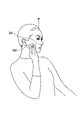
- FIG. 1 is a diagram showing a usage state of a beauty device according to an embodiment.
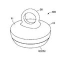
- FIG. 2 is a diagram showing the beauty device of the first embodiment.
- 3 is a bottom view of the beauty device of FIG. 2
- FIG. 4 is a cross-sectional view taken along the line AA of FIG.
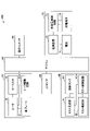
- FIG. 5 is a block diagram showing the internal configuration of the beauty device (first embodiment) of FIG. 2. As shown in FIG.
- the beauty device 100 that implements the beauty method of this embodiment has a contact surface CS that contacts a predetermined skin area SA.
- the predetermined skin area is not particularly limited, it is, for example, the cheek area SA of the user P (FIG. 1).
- the beauty device 100 of the present embodiment is used by the user P bringing the beauty device 100 into contact with the user P's cheek region SA.
- the beauty device 100 of the first embodiment has a main body 10 and a finger hook portion 20.
- the main body 10 is formed of a cylindrical insulating case.
- the main body 10 incorporates an assembly BA, which will be described later.
- the finger hook portion 20 is formed on the top surface 11 of the main body 10 and constitutes a handle for mounting the beauty device 100 on the user P. As shown in FIG.
- the bottom surface 12 of the main body 10 constitutes a contact surface CS that contacts the skin area SA.
- the beauty device 100 is operated by the user P by applying the contact surface CS of the beauty device 100 to the skin area SA (FIG. 1).
- the finger hook portion 20 of the beauty device 100 is formed in a ring shape.
- the beauty device 100 is worn by the user P by inserting the user's finger into the finger hook portion 20 (FIG. 2).
- the configuration of the beauty device 100 is not limited to the configuration shown in FIG. 2.
- a handle portion extending from a part of the side surface of the main body 10 is provided, and the user P grips this handle portion. Therefore, the user P may be able to operate the beauty device 100 .
- An assembly BA built into the main body 10 of the beauty device 100 has a heating section 30, an application section 40, a skin sensor 50, a microcomputer 60, and a power supply 70 (Figs. 3 and 4).
- the heating unit 30 is an example of a heating unit that constitutes a part of the beauty device of the present embodiment.
- the application unit 40 is an example of an application unit that constitutes a part of the beauty device of the present embodiment.
- the heating unit 30 has a function of heating the skin area SA.
- the heating unit 30 is arranged on the contact surface CS.
- the arrangement position of the heating unit 30 is not particularly limited.
- the heating part 30 is arranged in the circumferential direction on the bottom surface 12 side of the main body 10 (FIGS. 3 and 4).
- the heating unit 30 has a heating plate 31, a thermistor 32, and a heater 33 (Figs. 4 and 5).
- the warm plate 31 forms part of the contact surface CS and contacts the skin area SA.
- the warm plate 31 is connected to the heater 33 and transfers heat from the heater 33 to the skin area SA.
- the thermistor 32 is formed above the warm plate 31 and constitutes a temperature sensor that measures the temperature of the warm plate 31 .
- the thermistor 32 is communicably connected to the microcomputer 60 while being covered with the heater 33 .
- the thermistor 32 measures the heat generation temperature of the heater 33 and transmits the temperature information to the microcomputer 60 .
- the heater 33 heats the hot plate 31 .
- a heater 33 is formed above the warm plate 31 and incorporates a thermistor 32 .
- the heater 33 includes a heater drive circuit 33A communicatively connected to the microcomputer 60.
- a heater drive circuit 33A is controlled by the microcomputer 60, and the heater 33 heats the warm plate 31 (FIGS. 4 and 5).
- the mode of the heater 33 is not particularly limited, for example, a Peltier element can be used.
- the Peltier element can control the heat absorption by controlling the current, by adopting such a Peltier element for the heater 33, highly accurate and responsive heating control can be performed. In addition, since the Peltier element has a small volume, using such a Peltier element for the heater 33 facilitates miniaturization of the beauty device 100 .
- the application unit 40 has a function of applying cosmetics to the skin area SA.
- the application unit 40 is arranged side by side with the heating unit 30 on the contact surface CS.
- the applicator 40 is arranged in the center of the contact surface CS with a predetermined gap in the radial direction from the heating unit 30 . Thereby, the application section 40 is surrounded by the heating section 30 (FIGS. 3 and 4).
- cosmetics are not particularly limited. Any cosmetics for make-up (also referred to as make-up cosmetics) such as eyeliner, eye shadow, mascara, nail polish, and perfume are included. Also, applying means painting or spraying the cosmetic on the skin area.
- the application unit 40 includes a mist generation unit 41, a mist injection unit 42, and a liquid tank 43 (Figs. 4 and 5).
- the mist generating section 41 is formed above the heating section 30 and communicates with the passage PT.
- the passage PT is surrounded by the heating portion 30 in the circumferential direction and has an ejection port OP that opens to the contact surface CS.
- the mist generator 41 is connected to a liquid tank 43 in which cosmetics (not shown) are stored (Fig. 4).
- the mist generation unit 41 includes a mist control circuit 41A communicably connected to the microcomputer 60 (Figs. 4 and 5).
- the mist generator 41 has a mist control circuit 41A controlled by the microcomputer 60, and has a function of processing the cosmetics supplied from the liquid tank 43 into a mist (or atomized).
- the mist injection part 42 constitutes a part of the mist generation part 41 communicating with the passage PT.
- the mist injection unit 42 has a function of injecting cosmetic mist processed by the mist generation unit 41 .
- the cosmetic mist injected from the mist injection part 42 is discharged from the ejection port OP through the passage PT.
- the jet port OP is an example of a spray port of an application unit that sprays cosmetics in the beauty device of the present embodiment.
- the mist injection unit 42 is communicably connected to the microcomputer 60 via the mist control circuit 41A of the mist generation unit 41.
- a mist control circuit 41A is controlled by the microcomputer 60, and the mist injection part 42 injects cosmetic mist toward the passage PT.
- the liquid tank 43 stores liquid cosmetics.
- the liquid tank 43 is formed above the mist generator 41 and connected to the mist generator 41 (FIG. 4).
- the liquid tank 43 is communicably connected to the microcomputer 60 and supplies cosmetics to the mist generator 41 under the control of the microcomputer 60 (FIG. 5).
- the liquid tank 43 has a replenishment port (not shown) for replenishing the cosmetics supplied to the mist generating section 41 .
- the Peltier element can control heat absorption by controlling the current, so by adopting such a Peltier element in the application unit 40, highly accurate and responsive cooling control can be performed.
- the Peltier element has a small volume, using such a Peltier element in the application unit 40 facilitates downsizing of the beauty device 100 .
- the skin sensor 50 is arranged on the contact surface CS.
- the skin sensor 50 has a function of detecting the state of the skin area SA while the contact surface CS is in contact with the skin area SA.
- the arrangement position of the skin sensor 50 is not particularly limited. In this embodiment, the skin sensor 50 is arranged on the lower surface (contact surface CS) side of the warming plate 31 of the heating unit 30 (FIG. 4).
- the aspect of the skin sensor 50 is not particularly limited, and may be, for example, a temperature sensor, an acceleration sensor, or a position sensor, or a combination of two or more of these.
- the skin sensor 50 is a temperature sensor
- the state of the skin area SA is the temperature of the skin area SA
- the skin sensor 50 contacts the skin area SA to detect the temperature of the skin area SA.
- the microcomputer 60 is arranged above the heating section 30 with the heating section 30 separated from the lower partition wall LB. Further, the microcomputer 60 is arranged below the mist generating section 41 of the coating section 40 with the mist generating section 41 separated from the upper partition wall UB (FIG. 4).
- the microcomputer 60 has a central processing unit (CPU) and memory (both not shown).
- the microcomputer 60 is connected to the heating section 30, the application section 40, the skin sensor 50, the power source 70, and the operating switch 80, and can control the beauty device 100 (FIGS. 4 and 5).
- the CPU of the microcomputer 60 controls the heating unit 30, the application unit 40, the skin sensor 50, and the power supply 70, and performs various processes such as calculation, storage, transfer, input, and output of information. Note that the CPU may be configured separately from the microcomputer 60 .
- the memory of the microcomputer 60 constitutes a temporary storage device that stores information that is calculated when the CPU executes processing.
- the beauty device 100 may include auxiliary devices (not shown) such as a hard disk drive (HDD) and a modular jack.
- the microcomputer 60 controls the amount of cosmetics applied by the application unit 40 . Specifically, the microcomputer 60 can control the application time of cosmetics.
- the mode of controlling the application time of the cosmetic is not particularly limited.
- the microcomputer 60 can control the spray amount of the cosmetic that is sprayed (jetted) from the spray port (jet port OP). In addition, the microcomputer 60 can control the spray time of the cosmetic sprayed (jetted) from the spray port (jet port OP).
- the microcomputer 60 can control the amount of cosmetic applied based on the temperature of the skin area SA detected by the skin sensor 50 (temperature sensor). It should be noted that the microcomputer 60 is an example of a control section that constitutes a part of the beauty equipment of this embodiment.
- the power supply 70 is arranged above the application section 40 (liquid tank 43).
- the power supply 70 has a battery 71, a power supply circuit 72, a charge/discharge control circuit 73, and a charging terminal 74 (FIG. 5).
- the battery 71 is electrically connected to the charge/discharge control circuit 73, and constitutes the power source of the beauty device 100 (Fig. 5).
- the power supply circuit 72 is energized and connected to the microcomputer 60 and the charge/discharge control circuit 73 .
- power discharged from the battery 71 is supplied to the beauty device 100 via the charge/discharge control circuit 73 (FIG. 5).
- the charge/discharge control circuit 73 is electrically connected to the battery 71, the power supply circuit 72, and the charging terminal 74.
- the charge/discharge control circuit 73 charges and discharges the battery 71 under the control of the microcomputer 60 (FIG. 5).
- the charging terminal 74 is electrically connected to the charge/discharge control circuit 73 . At the charging terminal 74, electric power for charging the battery 71 is taken in from the outside via the charging/discharging control circuit 73 (FIG. 5).
- the operation switch 80 is communicably connected to the microcomputer 60 .
- the user P can switch on/off of the beauty device 100, processing specifications, etc. by operating the operation switch 80 (FIG. 5).
- the heating unit 30 that heats the skin area SA and the application unit 40 that applies the cosmetic to the skin area SA are arranged on the contact surface CS, and the application of the cosmetic by the application unit 40 is performed.
- the application amount By controlling the application amount by the microcomputer 60, it is possible to prevent deterioration of the thermal effect due to the heat of vaporization of the applied cosmetic. Thereby, in this embodiment, a cosmetic effect can be obtained without reducing the thermal effect.
- the microcomputer 60 controls the application time of the cosmetic, thereby facilitating prevention of deterioration in the thermal effect due to the heat of vaporization of the applied cosmetic.
- the microcomputer 60 controls the application time of the cosmetic, thereby facilitating prevention of deterioration in the thermal effect due to the heat of vaporization of the applied cosmetic.
- the application unit 40 can easily apply the cosmetic by having the spray port (jet port OP) for spraying the cosmetic.
- the spray port jet port OP
- a cosmetic effect and a thermal effect can be easily obtained.
- the microcomputer 60 controls the spray amount of the cosmetic, thereby facilitating control of the application amount of the cosmetic by the application section 40 . Further, in the present embodiment, as described above, the microcomputer 60 controls the spraying time of the cosmetic, thereby making it easier to control the amount of the cosmetic applied by the application unit 40 . Thereby, in this embodiment, the cosmetic effect and the thermal effect can be obtained more easily.
- the temperature sensor is provided as the skin sensor 50, and the microcomputer 60 determines the application amount of the cosmetic based on the temperature of the skin area SA detected by the skin sensor 50 (temperature sensor).
- the thermal effect can be obtained efficiently without degrading the cosmetic effect.
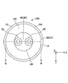
- FIG. 6 is a diagram of the beauty device of the embodiment (second embodiment) viewed from the bottom side. 7 is a cross-sectional view taken along the line BB of FIG. 6.
- FIG. FIG. 8 is a block diagram showing the internal configuration of the beauty device (second embodiment) of FIG.
- parts common to the first embodiment are denoted by the same reference numerals as in FIGS. 3 to 5, and description thereof is omitted.
- mist generating units 41 of the application unit 40 are arranged within the passage PT.
- a mist injection unit 42 is provided in each of the two mist generation units 41 .
- the mist injection part 42 is arranged on the side of the ejection port OP, and is configured such that the opening area expands toward the ejection port OP (FIG. 7).
- the mist generators 41 are connected to the liquid tank 43 through the flow paths LP (FIG. 8).
- the two mist generating units 41 are provided with the mist injection units 42, respectively.
- Each may be good, and three or more may be good at a time.
- the liquid tank 43 is connected through a flow path AP to a solenoid valve 92 of a pump mechanism 90 arranged above.
- the pump mechanism 90 has an air pump 91 and an electromagnetic valve 92 .
- the air pump 91 is arranged above the solenoid valve 92 and is connected to the solenoid valve 92 through a flow passage AP (FIGS. 7 and 8).
- the air pump 91 includes a pump control circuit 91A communicably connected to the microcomputer 60 (Fig. 8).
- the pump control circuit 91A is communicably connected to the air pump 91 and the solenoid valve 92 .
- a microcomputer 60 controls a pump control circuit 91 A of the air pump 91 to drive the air pump 91 and open and close a solenoid valve 92 to increase the liquid pressure in the liquid tank 43 .
- the cosmetic is supplied from the liquid tank 43 to the mist generating section 41 in a pressurized state, and the makeup processed into a mist (or mist) in the mist generating section 41 is supplied to the mist generating section 41.
- the mist is jetted from the mist jetting part 42 vigorously.
- the cosmetic material processed into mist (or atomized) by the mist generating unit 41 is sprayed from the mist spraying unit 42 while being pressurized by the pump mechanism 90.
- This facilitates control of the amount of the cosmetic applied by the application unit 40 . Specifically, it becomes easier to control the spray amount of the cosmetic and control the spray time of the cosmetic.
- FIG. 9 is a flow chart of the beauty method according to the embodiment.
- FIG. 10 is a diagram showing a timing chart of the heating process and the application process in the cosmetic method of the embodiment.
- steps S1 to S6 are executed.
- the cosmetic method of the present embodiment is not particularly limited, but is implemented, for example, by implementing the cosmetic device 100 described above.
- step S1 a coating process is executed.
- a cosmetic is applied to the skin area (Fig. 9).
- the cosmetic processed into a mist is jetted from the ejection port OP of the application unit 40 onto the skin area SA of the user P (FIGS. 1 to 5).
- the ingredients of the cosmetic are not particularly limited, it preferably contains a non-volatile ingredient.
- the amount of the cosmetic to be applied is arbitrary, but can be, for example, 0.1 ⁇ L or more and 0.5 ⁇ L ⁇ , preferably 0.15 ⁇ L or more and 0.35 ⁇ L, in a square area of 30 mm ⁇ 30 mm in one application. Below, more preferably 0.2 ⁇ L or more and 0.3 ⁇ L or less.
- the application time P A of the cosmetic is arbitrary, but for example, it can be 1 second or more and 9 seconds or less per application, preferably 2 seconds or more and 8 seconds or less, more preferably 3 seconds or more. 7 seconds or less (FIGS. 6 and 10).
- the application step may be performed simultaneously with the heating step, or the heating step may be performed separately.
- the coating process is performed during a period (coating time P A ) in which the heating process is not performed (FIGS. 6 and 10).
- step S2 a heating process is performed.
- the skin area is warmed.
- the heating unit 30 heats the skin area SA of the user P to which the cosmetic is applied under the control of the microcomputer 60 (FIGS. 1 to 5).
- the temperature for heating the skin area SA is arbitrary, but for example, it is a temperature higher than the skin temperature, preferably 35°C or higher and 45°C or lower, more preferably 38°C or higher and 42°C.
- the skin temperature indicates the surface temperature of the skin area SA and is 30°C to 32°C.
- the time PH for heating the skin area SA is arbitrary, but can be, for example, 0.3 seconds or more and 2 seconds or less, preferably 0.5 seconds or more and 1.5 seconds or less, more preferably 0 seconds. 0.8 seconds or more and 1.2 seconds or less (FIG. 10).
- the heating process may be performed simultaneously with the coating process, or may be performed separately from the coating process.
- the heating process is performed during the period (heating time P H ) in which the coating process is not performed (FIGS. 6 and 10).
- step S3 the temperature measurement process is executed.
- the temperature measurement step detects the temperature of the skin area.
- the skin sensor 50 (temperature sensor) detects the temperature of the skin area SA of the user P to which the cosmetics are applied and heated under the control of the microcomputer 60 .
- a control process is executed in steps S4 and S5.
- the application amount of the cosmetic is controlled based on the temperature detected in the temperature detection step (step S3).
- the predetermined temperature is arbitrary, but preferably set to a temperature higher than the temperature of the skin, for example.
- step S4 When it is determined in step S4 that the temperature of the skin area is equal to or higher than the predetermined temperature, the process proceeds to step S5, and the application amount of the cosmetic is controlled based on the detected temperature of the skin area SA. On the other hand, when it is determined that the temperature of the skin area SA is lower than the predetermined temperature, the process returns to step S2 and the heating process is performed.
- step S6 if steps S1 to S5 are to be repeated, the process returns to step S1, and if steps S1 to S5 are not to be repeated, the process ends (FIG. 9). It should be noted that steps S1 to S5 constitute one cycle (cycle T 1 ) (FIG. 10).
- steps S1 to S5 When steps S1 to S5 are to be repeated, one more cycle of steps S1 to S5 is performed (cycle T 2 ).
- one cycle of steps S1 to S5 is performed ten times (cycles T 0 to T 10 ), but the number of cycles is not limited to ten. It can be up to 5 cycles, preferably 5 cycles or more, more preferably 8 cycles.
- the heating process, the application process, the temperature measurement process, and the control process are executed in steps S1 to S6.
- An effect similar to that obtained by That is, according to the beauty treatment method of the present embodiment, it is possible to prevent deterioration of the thermal effect due to the heat of vaporization of the applied cosmetic, and to easily obtain the cosmetic effect and the thermal effect.
- the temperature of the skin area is measured by attaching a thermocouple to the skin area and recording with a data logger (Memory Hilogger LR8431 manufactured by Hioki Electric Co., Ltd.) from 10 seconds before application (Fig. 10, time T S ) to after application. Measurements were taken up to 20 seconds (FIG. 10, time T E ).
- a data logger Memory Hilogger LR8431 manufactured by Hioki Electric Co., Ltd.
- Base ion-exchanged water as a volatile component and glycerin as a nonvolatile component were mixed to prepare four levels with different blending ratios of glycerin.
- the base is assumed to be a cosmetic.
Landscapes
- Health & Medical Sciences (AREA)
- Life Sciences & Earth Sciences (AREA)
- Public Health (AREA)
- Veterinary Medicine (AREA)
- Animal Behavior & Ethology (AREA)
- General Health & Medical Sciences (AREA)
- Epidemiology (AREA)
- Birds (AREA)
- Engineering & Computer Science (AREA)
- Biomedical Technology (AREA)
- Heart & Thoracic Surgery (AREA)
- Vascular Medicine (AREA)
- Emergency Medicine (AREA)
- Dermatology (AREA)
- Devices For Medical Bathing And Washing (AREA)
Abstract
所定の皮膚領域に接触する接触面を有する美容機器であって、前記接触面に配置され、前記皮膚領域を加温する加温部と、前記接触面に配置され、前記皮膚領域に化粧料を塗布する塗布部と、前記塗布部による前記化粧料の塗布量を制御する制御部とを有する、美容機器。
Description
本開示は、美容機器、及び美容方法に関する。
現代人は、エアコンの普及により環境温度が一定で保たれているため、血液循環による皮膚温の調整能力が低下していると言われている。また、運動不足や温浴率の低下も重なって、血管拡張の機会が減り、現代人は、恒常的な血管収縮状態の傾向にある。恒常的な血管収縮状態は、顔の肌などに栄養が行き渡らなくなり、ターンオーバーが遅くなる、血管密度の低下により肌の弾力が低下する、肌にくすみが出る等、肌状態に悪影響を及ぼす。
このような血管収縮状態を改善するため、従来から化粧品と温熱機器を併用することで化粧効果と温熱効果の同時ケアを行う技術がある。例えば、特許文献1には、化粧品をスチーム状態で皮膚に供給する美容機器が開示されている。
しかしながら、化粧効果と温熱効果の同時ケアを行う技術では、塗布された化粧品の気化熱により、温熱効果が持続せずに低下する。
本発明の課題は、温熱効果の低下させずに化粧効果が得られる美容機器を提供することである。
上記課題を解決するため、本開示の一態様は、所定の皮膚領域に接触する接触面を有する美容機器であって、前記接触面に配置され、前記皮膚領域を加温する加温部と、前記接触面に配置され、前記皮膚領域に化粧料を塗布する塗布部と、前記塗布部による前記化粧料の塗布量を制御する制御部とを有する、美容機器を提供する。
本開示の一態様によれば、温熱効果を低下させずに化粧効果を得ることができる。
本発明の実施の形態について、図面を参照しながら説明する。なお、各図において共通する部分については、同一の符号を付して説明を省略する場合がある。また、各図における各部材の縮尺は、実際とは異なる場合がある。
本明細書では、3軸方向(X方向、Y方向、Z方向)の3次元直交座標系を用い、美容機器の横幅方向(または径方向)をX方向とし、縦幅方向(または径方向)をY方向とし、高さ方向をZ方向とする。また、上方は美容機器の高さ方向の上側を示し、下方は美容機器の高さ方向の下側を示す。
<美容機器>
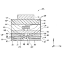
図1は、実施形態の美容機器の使用状態を示す図である。図2は、第1実施形態の美容機器を示す図である。図3は、図2の美容機器を底面側から見た図であり、図4は、図3のA-A線断面図である。図5は、図2の美容機器(第1実施形態)の内部構成を示すブロック図である。
図1は、実施形態の美容機器の使用状態を示す図である。図2は、第1実施形態の美容機器を示す図である。図3は、図2の美容機器を底面側から見た図であり、図4は、図3のA-A線断面図である。図5は、図2の美容機器(第1実施形態)の内部構成を示すブロック図である。
本実施形態の美容方法を実現する美容機器100は、所定の皮膚領域SAに接触する接触面CSを有する。所定の皮膚領域は、特に限定されないが、例えば、ユーザPの頬の領域SAである(図1)。本実施形態の美容機器100は、ユーザPが美容機器100をユーザPの頬の領域SAに接触させて使用される。
第1実施形態の美容機器100は、本体10と指掛部20を有する。本体10は、円筒状の絶縁ケースで形成されている。本体10には、後述するアセンブリBAが内蔵されている。指掛部20は、本体10の天面11に形成され、美容機器100をユーザPに装着するための取っ手を構成する。
本体10の底面12は、皮膚領域SAに接触する接触面CSを構成する。美容機器100は、ユーザPが皮膚領域SAに美容機器100の接触面CSを当てて操作される(図1)。
本実施形態では、美容機器100の指掛部20がリング状に形成されている。美容機器100では、この指掛部20にユーザPが指を挿入することで、ユーザPに装着される(図2)。なお、美容機器100の形態は図2の構成に限定されず、例えば、指掛部20の代わりに本体10の側面の一部から延びる持手部を備え、ユーザPがこの持手部を握ることで、ユーザPが美容機器100を操作できるものでもよい。
美容機器100の本体10に内蔵されているアセンブリBAは、加温部30、塗布部40、肌センサ50、マイコン60、電源70を有する(図3、図4)。このうち、加温部30は、本実施形態の美容機器の一部を構成する加温部の一例である。また、塗布部40は、本実施形態の美容機器の一部を構成する塗布部の一例である。
加温部30は、皮膚領域SAを加温する機能を有する。加温部30は、接触面CSに配置されている。加温部30の配置位置は、特に限定されない。本実施形態では、加温部30は、本体10の底面12側の周方向に配置されている(図3、図4)。
加温部30は、温プレート31、サーミスタ32、ヒータ33を有する(図4、図5)。
温プレート31は、接触面CSの一部を構成し、皮膚領域SAに接触する。温プレート31は、ヒータ33に接続され、ヒータ33からの熱を皮膚領域SAに伝える。
サーミスタ32は、温プレート31の上方に形成され、温プレート31の温度を測定する温度センサを構成する。サーミスタ32は、ヒータ33に覆われた状態でマイコン60に通信可能に接続されている。サーミスタ32は、ヒータ33の発熱温度を測定し、その温度情報をマイコン60に伝送する。
ヒータ33は、温プレート31を加熱する。ヒータ33は、温プレート31の上方に形成されて、サーミスタ32を内蔵する。ヒータ33は、マイコン60に通信可能に接続されたヒータ駆動回路33Aを備える。ヒータ33は、マイコン60によりヒータ駆動回路33Aが制御され、温プレート31を加熱する(図4、図5)。ヒータ33の態様は、特に限定されないが、例えば、ペルチェ素子を用いることができる。
なお、ペルチェ素子は、電流の制御により吸熱をコントロールすることができるため、このようなペルチェ素子をヒータ33に採用することで、高い精度、応答性の加熱制御を行うことができる。また、ペルチェ素子は、その体積が小さいため、このようなペルチェ素子をヒータ33に採用することで、美容機器100の小型化が容易になる。
塗布部40は、皮膚領域SAに化粧料を塗布する機能を有する。塗布部40は、接触面CSに加温部30と並んで配置されている。本実施形態では、塗布部40は、加温部30と径方向に所定の間隔を開けて、接触面CSの中央に配置されている。これにより、塗布部40は、加温部30に囲まれている(図3、図4)。
本明細書において、化粧料は、特に限定されず、例えば、化粧水、美容液、乳液、クリーム等のスキンケア用の化粧料(基礎化粧品ともいう)、およびファンデーション、チーク、口紅、グロス、眉墨、アイライナー、アイシャドー、マスカラ、マニキュア、香水等のメイクアップ用の化粧料(メイクアップ化粧品ともいう)のいずれも対象に含まれる。また、塗布とは、化粧料を皮膚領域に塗るまたは噴霧することを示す。
塗布部40は、ミスト生成部41、ミスト噴射部42、液体タンク43を備える(図4、図5)。
ミスト生成部41は、加温部30の上方に形成され、通路PTに連通する。なお、通路PTは、周方向を加温部30に囲まれ、接触面CSに開口する噴出口OPを有する。ミスト生成部41は、化粧料(図示せず)が貯蔵された液体タンク43に接続されている(図4)。
ミスト生成部41は、マイコン60に通信可能に接続されたミスト制御回路41Aを備える(図4、図5)。ミスト生成部41は、マイコン60によりミスト制御回路41Aが制御され、液体タンク43から供給された化粧料をミスト(または霧状)に加工する機能を有する。
ミスト噴射部42は、通路PTに連通するミスト生成部41の一部を構成する。ミスト噴射部42は、ミスト生成部41で加工された化粧料のミストを噴射する機能を有する。ミスト噴射部42から噴射された化粧料のミストは、通路PTを通じて噴出口OPから放出される。なお、噴出口OPは、本実施形態の美容機器において化粧料を噴霧する塗布部の噴霧口の一例である。
ミスト噴射部42は、ミスト生成部41のミスト制御回路41Aを介してマイコン60に通信可能に接続されている。ミスト噴射部42は、マイコン60によりミスト制御回路41Aが制御され、化粧料のミストを通路PTに向けて噴射する。
液体タンク43は、液体の化粧料を貯蔵する。液体タンク43は、ミスト生成部41の上方に形成され、ミスト生成部41に接続されている(図4)。液体タンク43は、マイコン60に通信可能に接続され、マイコン60の制御により、化粧料をミスト生成部41に供給する(図5)。液体タンク43は、ミスト生成部41に供給される化粧料を補給するための補給口(図示せず)を有する。
なお、ペルチェ素子は、電流の制御により吸熱をコントロールすることができるため、このようなペルチェ素子を塗布部40に採用することで、高い精度、応答性の冷却制御を行うことができる。また、ペルチェ素子は、その体積が小さいため、このようなペルチェ素子を塗布部40に採用することで、美容機器100の小型化が容易になる。
肌センサ50は、接触面CSに配置されている。肌センサ50は、接触面CSが皮膚領域SAに接触した状態で皮膚領域SAの状態を検知する機能を有する。肌センサ50の配置位置は、特に限定されない。本実施形態では、加温部30の温プレート31の下面(接触面CS)側に肌センサ50が配置されている(図4)。
肌センサ50の態様は、特に限定されず、例えば、温度センサ、加速度センサ、または位置センサ等であり、これらの2種以上を組み合わせたものでもよい。なお、本実施形態では、肌センサ50が温度センサの場合は、皮膚領域SAの状態は皮膚領域SAの温度であり、肌センサ50が皮膚領域SAに接触して皮膚領域SAの温度を検知する。
マイコン60は、加温部30の上方に、加温部30と下部隔壁LBを隔てて配置されている。また、マイコン60は、塗布部40のミスト生成部41の下方に、ミスト生成部41と上部隔壁UBを隔てて配置されている(図4)。
マイコン60は、中央処理装置(CPU)、メモリー(いずれも図示せず)を有する。マイコン60は、加温部30、塗布部40、肌センサ50、電源70、操作スイッチ80に接続され、美容機器100を制御することができる(図4、図5)。
マイコン60は、マイコン60のCPUが、加温部30、塗布部40、肌センサ50、電源70を制御し、情報の演算、記憶、転送、入力、出力等の各処理を行う。なお、CPUは、マイコン60と別個に構成してもよい。
マイコン60のメモリーは、CPUが処理を実行する際に演算する情報を記憶する一時記憶装置を構成する。なお、美容機器100では、ハードディスクドライブ(HDD)、モジュラージャック等の補助装置(図示せず)を備えていてもよい。
マイコン60は、塗布部40による化粧料の塗布量を制御する。具体的には、マイコン60は、化粧料の塗布時間を制御することができる。なお、化粧料の塗布時間を制御する態様は、特に限定されないが、例えば、マイコン60の制御により、塗布部40が化粧料を間欠塗布してもよい。
また、マイコン60は、噴霧口(噴出口OP)から噴霧(噴出)される化粧料の噴霧量を制御することができる。また、マイコン60は、噴霧口(噴出口OP)から噴霧(噴出)される化粧料の噴霧時間を制御することができる。
また、肌センサ50が温度センサの場合、マイコン60は、肌センサ50(温度センサ)が検知した皮膚領域SAの温度に基づいて化粧料の塗布量を制御することができる。なお、マイコン60は、本実施形態の美容機器の一部を構成する制御部の一例である。
電源70は、塗布部40(液体タンク43)の上方に配置されている。電源70は、電池71、電源回路72、充放電制御回路73、充電端子74を有する(図5)。
電池71は、充放電制御回路73に通電可能に接続され、美容機器100の電力源を構成する(図5)。
電源回路72は、マイコン60及び充放電制御回路73に通電可能に接続されている。電源回路72では、充放電制御回路73を介して電池71が放電した電力が美容機器100に供給される(図5)。
充放電制御回路73は、電池71、電源回路72、充電端子74に通電可能に接続されている。充放電制御回路73では、マイコン60の制御により、電池71の充放電が行われる(図5)。
充電端子74は、充放電制御回路73に通電可能に接続されている。充電端子74では、充放電制御回路73を介して電池71に充電する電力が外部から取り込まれる(図5)。
操作スイッチ80は、マイコン60に通信可能に接続されている。ユーザPは、操作スイッチ80を操作することにより、美容機器100のオン-オフ、処理の仕様等を切り替えることができる(図5)。
本実施形態では、上述のように、皮膚領域SAを加温する加温部30と皮膚領域SAに化粧料を塗布する塗布部40とが接触面CSに配置され、塗布部40による化粧料の塗布量をマイコン60が制御することで、塗布された化粧料の気化熱による温熱効果の低下を防ぐことができる。これにより、本実施形態では、温熱効果を低下させずに化粧効果を得ることができる。
また、本実施形態では、上述のように、マイコン60が化粧料の塗布時間を制御することで、塗布された化粧料の気化熱による温熱効果の低下を防ぐことが容易になる。なお、マイコン60の制御により、化粧料を間欠塗布することで、塗布された化粧料の気化熱による温熱効果の低下を防ぐことがさらに容易になる。
また、本実施形態では、上述のように、塗布部40が化粧料を噴霧する噴霧口(噴出口OP)を有することで、塗布部40による化粧料の塗布が容易である。これにより、本実施形態では、化粧効果と温熱効果が簡便に得られる。
また、本実施形態では、上述のように、マイコン60が化粧料の噴霧量を制御することで、塗布部40による化粧料の塗布量の制御が容易になる。また、本実施形態では、上述のように、マイコン60が化粧料の噴霧時間を制御することで、塗布部40による化粧料の塗布量の制御がさらに容易になる。これにより、本実施形態では、化粧効果と温熱効果がさらに簡便に得られる。
また、本実施形態では、上述のように、肌センサ50として温度センサを有し、肌センサ50(温度センサ)が検知した皮膚領域SAの温度に基づいて、マイコン60が化粧料の塗布量を制御することで、塗布された化粧料の気化熱による温熱効果の低下を防ぐことがさらに容易になる。これにより、本実施形態では、化粧効果を低下させずに温熱効果が効率的に得られる。
図6は、実施形態の美容機器(第2実施形態)を底面側から見た図である。図7は、図6のB-B線断面図である。図8は、図6の美容機器(第2実施形態)の内部構成を示すブロック図である。なお、図6~図8において、第1実施形態と共通する部分は、図3~図5に付した符号を付して説明を省略する。
第2実施形態の美容機器100は、塗布部40のミスト生成部41が通路PT内に2つ配置されている。2つのミスト生成部41には、それぞれミスト噴射部42が設けられている。ミスト噴射部42は、噴出口OP側に配置され、噴出口OPに向かって開口面積が拡がるように構成されている(図7)。また、ミスト生成部41は、それぞれ流路LPを通じて液体タンク43に接続されている(図8)。
なお、第2実施形態では、2つのミスト生成部41にそれぞれミスト噴射部42が設けられているが、ミスト生成部41およびミスト噴射部42の数は、2つずつに限定されず、1つずつでもよいし、3つ以上ずつでもよい。
液体タンク43は、上方に配置されたポンプ機構90の電磁弁92に流路APを通じて接続されている。ポンプ機構90は、エアポンプ91、電磁弁92を備える。エアポンプ91は、電磁弁92の上方に配置され、流路APを通じて接続され電磁弁92に接続されている(図7、図8)。
エアポンプ91は、マイコン60に通信可能に接続されたポンプ制御回路91Aを備える(図8)。ポンプ制御回路91Aは、エアポンプ91および電磁弁92に通信可能に接続されている。エアポンプ91は、マイコン60によりポンプ制御回路91Aが制御され、エアポンプ91が駆動し、電磁弁92が開閉することで、液体タンク43内の液圧が高められる。
液体タンク43内の液圧が高められることで、液体タンク43からミスト生成部41に化粧料が加圧された状態で供給され、ミスト生成部41でミスト(または霧状)に加工された化粧料がミスト噴射部42から勢いよく噴射される。
第2実施形態の美容機器100では、ポンプ機構90により加圧された状態で、ミスト生成部41でミスト(または霧状)に加工された化粧料がミスト噴射部42から噴射されることで、塗布部40による化粧料の塗布量の制御が容易になる。具体的には、化粧料の噴霧量の制御、化粧料の噴霧時間の制御が容易になる。
<美容方法>
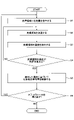
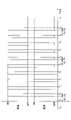
図9は、実施形態に係る美容方法のフローチャートである。図10は、実施形態の美容方法における加温工程と塗布工程のタイミングチャートを示す図である。本実施形態の美容方法では、ステップS1~ステップS6が実行される。本実施形態の美容方法は、特に限定されないが、例えば、上述の美容機器100を実施することにより実現される。
図9は、実施形態に係る美容方法のフローチャートである。図10は、実施形態の美容方法における加温工程と塗布工程のタイミングチャートを示す図である。本実施形態の美容方法では、ステップS1~ステップS6が実行される。本実施形態の美容方法は、特に限定されないが、例えば、上述の美容機器100を実施することにより実現される。
ステップS1では、塗布工程が実行される。塗布工程では、皮膚領域に化粧料が塗布される(図9)。具体的には、美容機器100において、マイコン60の制御により、ミストに加工された化粧料が塗布部40の噴出口OPからユーザPの皮膚領域SAに噴射される(図1~図5)。化粧料の成分は、特に限定されないが、不揮発成分が含まれていることが好ましい。
化粧料の塗布量は、任意であるが、例えば、1回の塗布で30mm×30mmの四方形の範囲に0.1μL以上0.5μLμにすることができ、好ましくは0.15μL以上0.35μL以下、より好ましくは0.2μL以上0.3μL以下にすることができる。また、化粧料の塗布時間PAは、任意であるが、例えば、1回の塗布で1秒以上9秒以下にすることができ、好ましくは2秒以上8秒以下、より好ましくは3秒以上7秒以下である(図6、図10)。
塗布工程は、加温工程と同時に実行してもよく、加温工程を別々に実行してもよい。本実施形態では、加温工程が実行されない期間(塗布時間PA)に塗布工程が実行される(図6、図10)。
ステップS2では、加温工程が実行される。加温工程では、皮膚領域が加温される。具体的には、美容機器100において、マイコン60の制御により、化粧料が塗布されたユーザPの皮膚領域SAが加温部30により加温される(図1~図5)。
皮膚領域SAを加温する温度は、任意であるが、例えば、肌の温度より高い温度であり、好ましくは35℃以上45℃以下であり、より好ましくは38℃以上42℃である。ここで、皮膚の温度は、皮膚領域SAの表面温度を示し、30℃~32℃である。
皮膚領域SAを加温する時間PHは、任意であるが、例えば、0.3秒以上2秒以下にすることができ、好ましくは0.5秒以上1.5秒以下、より好ましくは0.8秒以上1.2秒以下である(図10)。
加温工程は、塗布工程と同時に実行してもよく、塗布工程と別々に実行してもよい。本実施形態では、塗布工程が実行されない期間(加温時間PH)に加温工程が実行される(図6、図10)。
ステップS3では、検温工程が実行される。検温工程では、皮膚領域の温度を検出する。具体的には、美容機器100において、マイコン60の制御により、化粧料が塗布され、加温されたユーザPの皮膚領域SAの温度が肌センサ50(温度センサ)により検知される。
ステップS4、S5では、制御工程が実行される。制御工程では、検温工程(ステップS3)により検出した温度に基づいて化粧料の塗布量が制御される。具体的には、ステップS4で、皮膚領域の温度が所定温度以上であるかが判定される。ここで、所定温度は、任意であるが、例えば、肌の温度より高い温度に設定するのが好ましい。
ステップS4で、皮膚領域の温度が所定温度以上と判定された場合は、ステップS5に進み、検出した皮膚領域SAの温度に基づいて化粧料の塗布量が制御される。一方、皮膚領域SAの温度が所定温度未満と判定された場合は、ステップS2に戻り、加温工程が実行される。
ステップS6では、ステップS1~S5を繰り返す場合は、ステップS1に戻り、ステップS1~S5を繰り返さない場合は、ステップを終了する(図9)。なお、ステップS1~S5を1サイクル(サイクルT1)とする(図10)。
ステップS1~S5を繰り返す場合は、さらにステップS1~S5の1サイクルを行う(サイクルT2)。本実施形態では、図10に示すように、ステップS1~S5の1サイクルが10回行われているが(サイクルT0~T10)、サイクル数は10回に限定されず、2サイクル以上20サイクル以下することができ、好ましくは5サイクル以上、より好ましくは8サイクルである。
本実施形態の美容方法では、ステップS1~ステップS6で、加温工程、塗布工程、検温工程、及び制御工程(ステップS1~ステップS6)が実行されることで、上述のように、美容機器100による効果と同様の効果が得られる。すなわち、本実施形態の美容方法によれば、塗布された化粧料の気化熱による温熱効果の低下を防ぐことができ、化粧効果と温熱効果を簡便に得ることができる。
以下、本発明について、さらに実験例を用いて具体的に説明する。実験例の評価は、以下の実験により行った。
[実験条件]
温度25℃、湿度45%の恒温室で皮膚領域を加温することにより、皮膚領域の表面温度の変化を測定した。皮膚領域は、30mm×30mmの四方形とし、被験者の左腕に20mm間隔で3か所を設けた。皮膚領域の加温は、25℃の基剤を皮膚領域に5秒間塗布した後に、40℃±2℃で制御された電極を皮膚領域に1秒当てた。このサイクルを1サイクルとして10サイクル繰り返した(図10参照)。
温度25℃、湿度45%の恒温室で皮膚領域を加温することにより、皮膚領域の表面温度の変化を測定した。皮膚領域は、30mm×30mmの四方形とし、被験者の左腕に20mm間隔で3か所を設けた。皮膚領域の加温は、25℃の基剤を皮膚領域に5秒間塗布した後に、40℃±2℃で制御された電極を皮膚領域に1秒当てた。このサイクルを1サイクルとして10サイクル繰り返した(図10参照)。
皮膚領域の温度測定は、熱電対を皮膚領域に貼り付けて、データロガー(日置電機株式会社製、メモリハイロガーLR8431)で記録し、塗布前10秒(図10、時刻TS)から塗布後20秒(図10、時刻TE)まで測定した。算出方法は、基剤無塗布(処理前)の皮膚領域の表面温度からの温度変化に対して、基剤塗布時(処理後)の皮膚領域の温度変化の割合を算出した。
[基剤]
基剤は、揮発性成分としてイオン交換水、不揮発性成分としてグリセリンを混合し、グリセリンの配合比率が異なる4水準を作製した。なお、基剤は、化粧料を想定したものである。
基剤は、揮発性成分としてイオン交換水、不揮発性成分としてグリセリンを混合し、グリセリンの配合比率が異なる4水準を作製した。なお、基剤は、化粧料を想定したものである。
[評価方法]
算出した割合から下記の評価基準で評価した。なお、評価がA、B、Cのいずれかの場合は良好、評価がDの場合は、不良と判定した。
A:98%以上
B:95%以上98%未満
C:90%以上95%未満
D:90%未満
算出した割合から下記の評価基準で評価した。なお、評価がA、B、Cのいずれかの場合は良好、評価がDの場合は、不良と判定した。
A:98%以上
B:95%以上98%未満
C:90%以上95%未満
D:90%未満
[実験例1]
基剤における不揮発性成分の配合比率を0%とし、基剤の塗布量を0.25μLとして、評価した。結果を表1に示す。
基剤における不揮発性成分の配合比率を0%とし、基剤の塗布量を0.25μLとして、評価した。結果を表1に示す。
[実験例2]
基剤における不揮発性成分の配合比率を25%とした以外は、実験例1と同様に評価した。結果を表1に示す。
基剤における不揮発性成分の配合比率を25%とした以外は、実験例1と同様に評価した。結果を表1に示す。
[実験例3]
基剤における不揮発性成分の配合比率を50%とした以外は、実験例1と同様に評価した。結果を表1に示す。
基剤における不揮発性成分の配合比率を50%とした以外は、実験例1と同様に評価した。結果を表1に示す。
[実験例4]
基剤における不揮発性成分の配合比率を100%とした以外は、実験例1と同様に評価した。結果を表1に示す。
基剤における不揮発性成分の配合比率を100%とした以外は、実験例1と同様に評価した。結果を表1に示す。
[実験例5]
基剤の塗布量を0.5μLとした以外は、実験例1と同様に評価した。結果を表1に示す。
基剤の塗布量を0.5μLとした以外は、実験例1と同様に評価した。結果を表1に示す。
[実験例6]
基剤の塗布量を0.5μLとした以外は、実験例2と同様に評価した。結果を表1に示す。
基剤の塗布量を0.5μLとした以外は、実験例2と同様に評価した。結果を表1に示す。
[実験例7]
基剤の塗布量を0.5μLとした以外は、実験例3と同様に評価した。結果を表1に示す。
基剤の塗布量を0.5μLとした以外は、実験例3と同様に評価した。結果を表1に示す。
[実験例8]
基剤の塗布量を0.5μLとした以外は、実験例4と同様に評価した。結果を表1に示す。
基剤の塗布量を0.5μLとした以外は、実験例4と同様に評価した。結果を表1に示す。
[実験例9]
基剤の塗布量を1μLとした以外は、実験例1と同様に評価した。結果を表1に示す。
基剤の塗布量を1μLとした以外は、実験例1と同様に評価した。結果を表1に示す。
[実験例10]
基剤の塗布量を1μLとした以外は、実験例2と同様に評価した。結果を表1に示す。
基剤の塗布量を1μLとした以外は、実験例2と同様に評価した。結果を表1に示す。
[実験例11]
基剤の塗布量を1μLとした以外は、実験例3と同様に評価した。結果を表1に示す。
基剤の塗布量を1μLとした以外は、実験例3と同様に評価した。結果を表1に示す。
[実験例12]
基剤の塗布量を1μLとした以外は、実験例4と同様に評価した。結果を表1に示す。
基剤の塗布量を1μLとした以外は、実験例4と同様に評価した。結果を表1に示す。
[実験例13]
基剤の塗布量を2.5μLとした以外は、実験例1と同様に評価した。結果を表1に示す。
基剤の塗布量を2.5μLとした以外は、実験例1と同様に評価した。結果を表1に示す。
[実験例14]
基剤の塗布量を2.5μLとした以外は、実験例2と同様に評価した。結果を表1に示す。
基剤の塗布量を2.5μLとした以外は、実験例2と同様に評価した。結果を表1に示す。
[実験例15]
基剤の塗布量を2.5μLとした以外は、実験例3と同様に評価した。結果を表1に示す。
基剤の塗布量を2.5μLとした以外は、実験例3と同様に評価した。結果を表1に示す。
[実験例16]
基剤の塗布量を2.5μLとした以外は、実験例4と同様に評価した。結果を表1に示す。
基剤の塗布量を2.5μLとした以外は、実験例4と同様に評価した。結果を表1に示す。
[実験例17]
基剤の塗布量を5μLとした以外は、実験例1と同様に評価した。結果を表1に示す。
基剤の塗布量を5μLとした以外は、実験例1と同様に評価した。結果を表1に示す。
[実験例18]
基剤の塗布量を5μLとした以外は、実験例2と同様に評価した。結果を表1に示す。
基剤の塗布量を5μLとした以外は、実験例2と同様に評価した。結果を表1に示す。
[実験例19]
基剤の塗布量を5μLとした以外は、実験例3と同様に評価した。結果を表1に示す。
基剤の塗布量を5μLとした以外は、実験例3と同様に評価した。結果を表1に示す。
[実験例20]
基剤の塗布量を5μLとした以外は、実験例4と同様に評価した。結果を表1に示す。
基剤の塗布量を5μLとした以外は、実験例4と同様に評価した。結果を表1に示す。
[実験例21]
基剤の塗布量を10μLとした以外は、実験例1と同様に評価した。結果を表1に示す。
基剤の塗布量を10μLとした以外は、実験例1と同様に評価した。結果を表1に示す。
[実験例22]
基剤の塗布量を10μLとした以外は、実験例2と同様に評価した。結果を表1に示す。
基剤の塗布量を10μLとした以外は、実験例2と同様に評価した。結果を表1に示す。
[実験例23]
基剤の塗布量を10μLとした以外は、実験例3と同様に評価した。結果を表1に示す。
基剤の塗布量を10μLとした以外は、実験例3と同様に評価した。結果を表1に示す。
[実験例24]
基剤の塗布量を10μLとした以外は、実験例4と同様に評価した。結果を表1に示す。
基剤の塗布量を10μLとした以外は、実験例4と同様に評価した。結果を表1に示す。
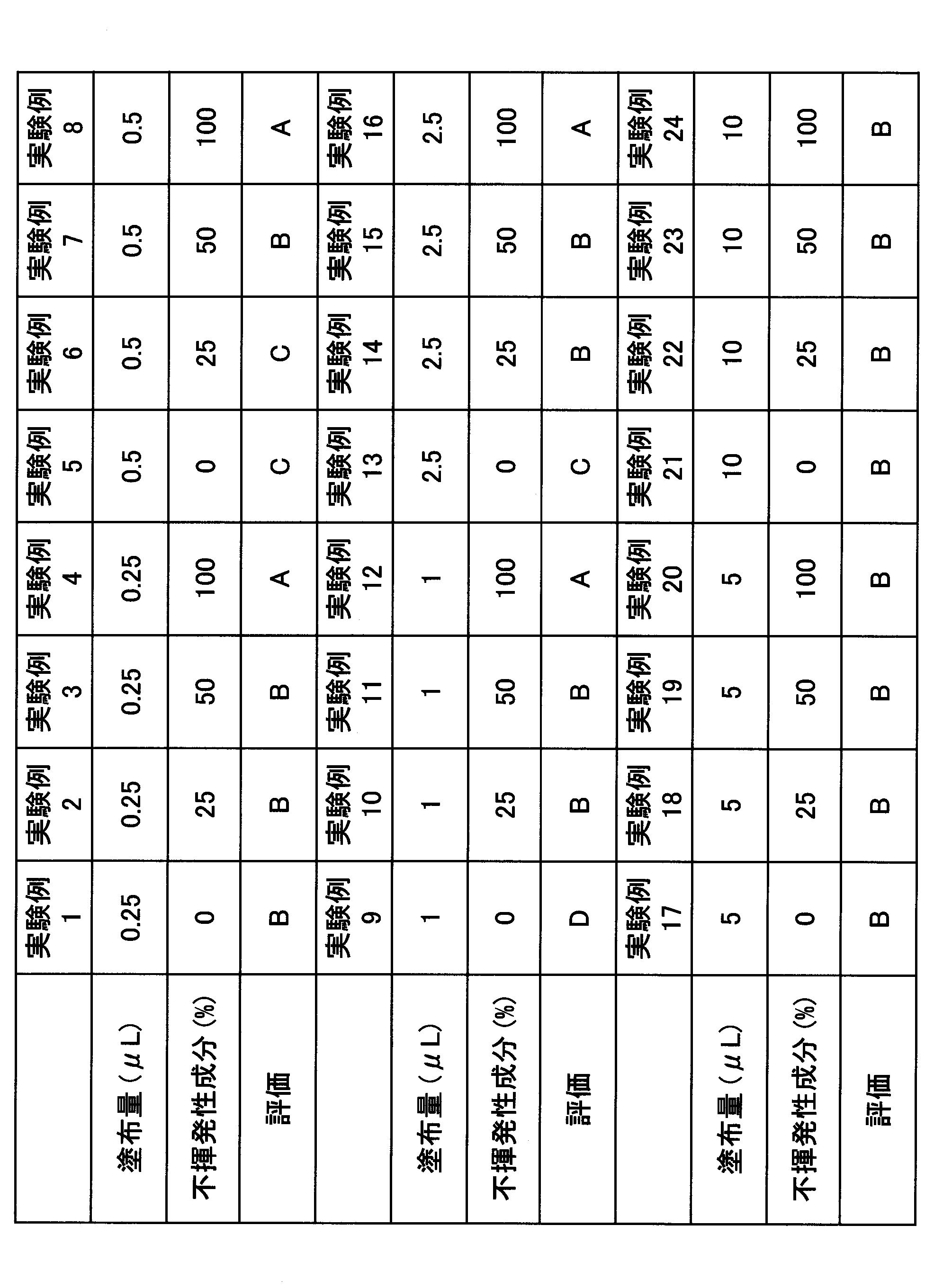
表1より、基剤無塗布(処理前)に対して、塗布した基剤の揮発性成分の比率が高いと塗布時の気化熱によって温熱効率を低下させるが、不揮発性成分を配合することで低下が抑制された。また、揮発成分が多い場合でも、塗布量を少なくすることで気化熱の吸熱よりも温熱効果が優位となり温熱効率の低下が抑制された。さらに、基剤の塗布量が多くなると、気化熱とは異なる基剤自体の温度で温熱効率が低下する。
したがって、塗布中の少量の基剤塗布であれば、基剤の揮発成分に関係なく温熱効果が損なわれずに化粧効果が得られることが判った。
以上、本発明の実施形態について説明したが、本発明は特定の実施形態に限定されるものではなく、請求の範囲に記載された発明の範囲内において、種々の変形、変更が可能である。
本出願は、2021年3月17日に出願された日本国特許出願2021-44057号に基づく優先権を主張するものであり、その全内容をここに援用する。
100 美容機器
10 本体
11 天面
12 底面
20 指掛部
BA アセンブリ
CS 接触面
30 加温部
31 温プレート
32 サーミスタ
33 ヒータ
33A ヒータ駆動回路
40 塗布部
41 ミスト生成部
41A ミスト制御回路
42 ミスト噴射部
43 液体タンク
PT 通路
LP 流路
AP 流路
50 肌センサ
60 マイコン
UB 上部隔壁
LB 下部隔壁
70 電源
71 電池
72 電源回路
73 充放電制御回路
74 充電端子
80 操作スイッチ
90 ポンプ機構
91 エアポンプ
91A ポンプ制御回路
92 電磁弁
P ユーザ
SA 皮膚領域
10 本体
11 天面
12 底面
20 指掛部
BA アセンブリ
CS 接触面
30 加温部
31 温プレート
32 サーミスタ
33 ヒータ
33A ヒータ駆動回路
40 塗布部
41 ミスト生成部
41A ミスト制御回路
42 ミスト噴射部
43 液体タンク
PT 通路
LP 流路
AP 流路
50 肌センサ
60 マイコン
UB 上部隔壁
LB 下部隔壁
70 電源
71 電池
72 電源回路
73 充放電制御回路
74 充電端子
80 操作スイッチ
90 ポンプ機構
91 エアポンプ
91A ポンプ制御回路
92 電磁弁
P ユーザ
SA 皮膚領域
Claims (8)
- 所定の皮膚領域に接触する接触面を有する美容機器であって、
前記接触面に配置され、前記皮膚領域を加温する加温部と、
前記接触面に配置され、前記皮膚領域に化粧料を塗布する塗布部と、
前記塗布部による前記化粧料の塗布量を制御する制御部と、を有する、
美容機器。 - 前記制御部は、前記化粧料の塗布時間を制御する、
請求項1に記載の美容機器。 - 前記制御部の制御により、前記化粧料を間欠塗布する、
請求項1または2に記載の美容機器。 - 前記塗布部は、前記化粧料を噴霧する噴霧口を有する、
請求項1乃至3のいずれか一項に記載の美容機器。 - 前記制御部は、前記化粧料の噴霧量を制御する、
請求項4に記載の美容機器。 - 前記制御部は、前記化粧料の噴霧時間を制御する、
請求項5に記載の美容機器。 - 温度センサを有し、
前記制御部は、前記温度センサが検知した前記皮膚領域の温度に基づいて前記化粧料の塗布量を制御する、
請求項1乃至6のいずれか一項に記載の美容機器。 - 皮膚領域を加温する加温工程と、
前記皮膚領域に化粧料を塗布する塗布工程と、
前記皮膚領域の温度を検出する検温工程と、を有し、
前記検温工程により検出した前記温度に基づいて前記化粧料の塗布量を制御する制御工程を、有する、
美容方法。
Priority Applications (1)
| Application Number | Priority Date | Filing Date | Title |
|---|---|---|---|
| JP2023507037A JPWO2022196504A1 (ja) | 2021-03-17 | 2022-03-09 |
Applications Claiming Priority (2)
| Application Number | Priority Date | Filing Date | Title |
|---|---|---|---|
| JP2021-044057 | 2021-03-17 | ||
| JP2021044057 | 2021-03-17 |
Publications (1)
| Publication Number | Publication Date |
|---|---|
| WO2022196504A1 true WO2022196504A1 (ja) | 2022-09-22 |
Family
ID=83320545
Family Applications (1)
| Application Number | Title | Priority Date | Filing Date |
|---|---|---|---|
| PCT/JP2022/010418 Ceased WO2022196504A1 (ja) | 2021-03-17 | 2022-03-09 | 美容機器、及び美容方法 |
Country Status (2)
| Country | Link |
|---|---|
| JP (1) | JPWO2022196504A1 (ja) |
| WO (1) | WO2022196504A1 (ja) |
Citations (3)
| Publication number | Priority date | Publication date | Assignee | Title |
|---|---|---|---|---|
| JP2003210248A (ja) * | 2001-10-22 | 2003-07-29 | Hewlett Packard Co <Hp> | 化粧品塗布器具 |
| JP2013537811A (ja) * | 2010-09-10 | 2013-10-07 | ロレアル | 美容製品のための加熱、収容および塗布用デバイス |
| KR102220549B1 (ko) * | 2020-08-18 | 2021-02-26 | 박형우 | 피부 미용기기 |
-
2022
- 2022-03-09 JP JP2023507037A patent/JPWO2022196504A1/ja active Pending
- 2022-03-09 WO PCT/JP2022/010418 patent/WO2022196504A1/ja not_active Ceased
Patent Citations (3)
| Publication number | Priority date | Publication date | Assignee | Title |
|---|---|---|---|---|
| JP2003210248A (ja) * | 2001-10-22 | 2003-07-29 | Hewlett Packard Co <Hp> | 化粧品塗布器具 |
| JP2013537811A (ja) * | 2010-09-10 | 2013-10-07 | ロレアル | 美容製品のための加熱、収容および塗布用デバイス |
| KR102220549B1 (ko) * | 2020-08-18 | 2021-02-26 | 박형우 | 피부 미용기기 |
Also Published As
| Publication number | Publication date |
|---|---|
| JPWO2022196504A1 (ja) | 2022-09-22 |
Similar Documents
| Publication | Publication Date | Title |
|---|---|---|
| EP4213682B1 (en) | Hair treatment system with proximity sensors to detect scalp or hair distance and locality | |
| CN105992609B (zh) | 具有储存器的离子电渗装置 | |
| KR101399151B1 (ko) | 가열된 마스카라 도포기 및 적합한 조성물 | |
| US7380556B2 (en) | Hair iron | |
| US20220088407A1 (en) | Hair treatment system with proximity sensors to detect scalp or hair distance and locality | |
| JP4752809B2 (ja) | スキンケア装置 | |
| KR20080010304A (ko) | 피부 관리 기구 | |
| JP2019146677A (ja) | 頭皮ケア装置 | |
| JP2018537240A (ja) | ヒトケラチン物質を、特に電流を用いて処理するためのデバイス | |
| KR20140123796A (ko) | 피부 건조에 따른 실시간 대응이 가능한 휴대용 미스트기 | |
| KR20230137908A (ko) | 헤어 케어 장치 | |
| KR20180084110A (ko) | 특히 전류의 도움으로, 인간 케라틴 물질을 처리하기 위한 디바이스 | |
| US20060207013A1 (en) | Shower mounted facial treatment cocoon | |
| WO2010087488A1 (ja) | ミスト発生装置 | |
| WO2010137503A1 (ja) | ミスト発生装置 | |
| JP2009165639A (ja) | ミスト発生装置 | |
| CN101588779B (zh) | 美容器 | |
| CN117979866A (zh) | 头发处理装置 | |
| JP4345715B2 (ja) | スチーム発生器 | |
| KR20240126057A (ko) | 증기 헤어 스타일링 기기 | |
| JP2018175319A (ja) | 水素水蒸気スプレーポット | |
| WO2022185978A1 (ja) | 美容方法、及び美容機器 | |
| JP7590027B2 (ja) | 美容機器 | |
| JP2015107804A (ja) | 液吐出容器 | |
| JP4675593B2 (ja) | 理美容機器 |
Legal Events
| Date | Code | Title | Description |
|---|---|---|---|
| 121 | Ep: the epo has been informed by wipo that ep was designated in this application |
Ref document number: 22771255 Country of ref document: EP Kind code of ref document: A1 |
|
| WWE | Wipo information: entry into national phase |
Ref document number: 2023507037 Country of ref document: JP |
|
| NENP | Non-entry into the national phase |
Ref country code: DE |
|
| 122 | Ep: pct application non-entry in european phase |
Ref document number: 22771255 Country of ref document: EP Kind code of ref document: A1 |