WO2022196489A1 - アルミニウム合金箔、アルミニウム積層体、及びアルミニウム合金箔の製造方法 - Google Patents
アルミニウム合金箔、アルミニウム積層体、及びアルミニウム合金箔の製造方法 Download PDFInfo
- Publication number
- WO2022196489A1 WO2022196489A1 PCT/JP2022/010291 JP2022010291W WO2022196489A1 WO 2022196489 A1 WO2022196489 A1 WO 2022196489A1 JP 2022010291 W JP2022010291 W JP 2022010291W WO 2022196489 A1 WO2022196489 A1 WO 2022196489A1
- Authority
- WO
- WIPO (PCT)
- Prior art keywords
- aluminum alloy
- alloy foil
- less
- aluminum
- mass
- Prior art date
- Legal status (The legal status is an assumption and is not a legal conclusion. Google has not performed a legal analysis and makes no representation as to the accuracy of the status listed.)
- Ceased
Links
Images
Classifications
-
- B—PERFORMING OPERATIONS; TRANSPORTING
- B22—CASTING; POWDER METALLURGY
- B22D—CASTING OF METALS; CASTING OF OTHER SUBSTANCES BY THE SAME PROCESSES OR DEVICES
- B22D11/00—Continuous casting of metals, i.e. casting in indefinite lengths
- B22D11/001—Continuous casting of metals, i.e. casting in indefinite lengths of specific alloys
- B22D11/003—Aluminium alloys
-
- B—PERFORMING OPERATIONS; TRANSPORTING
- B22—CASTING; POWDER METALLURGY
- B22D—CASTING OF METALS; CASTING OF OTHER SUBSTANCES BY THE SAME PROCESSES OR DEVICES
- B22D21/00—Casting non-ferrous metals or metallic compounds so far as their metallurgical properties are of importance for the casting procedure; Selection of compositions therefor
- B22D21/02—Casting exceedingly oxidisable non-ferrous metals, e.g. in inert atmosphere
- B22D21/04—Casting aluminium or magnesium
-
- C—CHEMISTRY; METALLURGY
- C22—METALLURGY; FERROUS OR NON-FERROUS ALLOYS; TREATMENT OF ALLOYS OR NON-FERROUS METALS
- C22C—ALLOYS
- C22C21/00—Alloys based on aluminium
-
- C—CHEMISTRY; METALLURGY
- C22—METALLURGY; FERROUS OR NON-FERROUS ALLOYS; TREATMENT OF ALLOYS OR NON-FERROUS METALS
- C22F—CHANGING THE PHYSICAL STRUCTURE OF NON-FERROUS METALS AND NON-FERROUS ALLOYS
- C22F1/00—Changing the physical structure of non-ferrous metals or alloys by heat treatment or by hot or cold working
- C22F1/04—Changing the physical structure of non-ferrous metals or alloys by heat treatment or by hot or cold working of aluminium or alloys based thereon
-
- H—ELECTRICITY
- H05—ELECTRIC TECHNIQUES NOT OTHERWISE PROVIDED FOR
- H05K—PRINTED CIRCUITS; CASINGS OR CONSTRUCTIONAL DETAILS OF ELECTRIC APPARATUS; MANUFACTURE OF ASSEMBLAGES OF ELECTRICAL COMPONENTS
- H05K1/00—Printed circuits
- H05K1/02—Details
- H05K1/09—Use of materials for the conductive, e.g. metallic pattern
-
- C—CHEMISTRY; METALLURGY
- C22—METALLURGY; FERROUS OR NON-FERROUS ALLOYS; TREATMENT OF ALLOYS OR NON-FERROUS METALS
- C22F—CHANGING THE PHYSICAL STRUCTURE OF NON-FERROUS METALS AND NON-FERROUS ALLOYS
- C22F1/00—Changing the physical structure of non-ferrous metals or alloys by heat treatment or by hot or cold working
-
- Y—GENERAL TAGGING OF NEW TECHNOLOGICAL DEVELOPMENTS; GENERAL TAGGING OF CROSS-SECTIONAL TECHNOLOGIES SPANNING OVER SEVERAL SECTIONS OF THE IPC; TECHNICAL SUBJECTS COVERED BY FORMER USPC CROSS-REFERENCE ART COLLECTIONS [XRACs] AND DIGESTS
- Y02—TECHNOLOGIES OR APPLICATIONS FOR MITIGATION OR ADAPTATION AGAINST CLIMATE CHANGE
- Y02E—REDUCTION OF GREENHOUSE GAS [GHG] EMISSIONS, RELATED TO ENERGY GENERATION, TRANSMISSION OR DISTRIBUTION
- Y02E60/00—Enabling technologies; Technologies with a potential or indirect contribution to GHG emissions mitigation
- Y02E60/10—Energy storage using batteries
Definitions
- the present invention relates to an aluminum alloy foil, an aluminum laminate, and a method for producing an aluminum alloy foil.
- Printed wiring boards are used in electrical and electronic equipment.
- a resist ink is printed in a pattern on the surface of an aluminum foil laminated on the board so as to form a desired wiring shape, and then immersed in an etching solution to print the resist ink. It is manufactured by melting the uncovered portion and forming the aluminum foil into a wiring pattern.
- JIS H4160 1000 series and 8000 series aluminum foils are used as aluminum foils for printed wiring boards.
- the aluminum foil described above has a slow dissolution rate in an etchant, making high-speed processing difficult.
- nickel (Ni) and one or two of zinc (Zn) and gallium (Ga) are included in the aluminum foil composition to increase the potential difference between the compound containing aluminum (Al) and nickel (Ni) and the mother phase.
- An aluminum alloy foil with improved solubility has been proposed (Patent Document 1).
- the aluminum foil for printed wiring boards is generally subjected to the final annealing process to remove the rolling oil, thereby maintaining the adhesion strength between the aluminum foil and the substrate, and also increasing the flexibility of the aluminum foil itself. is increasing.
- productivity tends to deteriorate, such as deterioration of workability in manufacturing printed wiring boards and an increased risk of wire disconnection in subsequent steps.
- Patent Document 2 by finely dispersing an aluminum-manganese-iron (Al-Mn-Fe) compound, it has high strength and excellent etching sensitivity, and further etching A technical proposal with excellent solubility has been proposed.
- Al-Mn-Fe aluminum-manganese-iron
- JP 2012-149289 A Japanese Patent Application Laid-Open No. 2001-152270
- Patent Document 2 The maximum tensile strength and 0.2% proof stress in Patent Document 2 are 124 N/mm 2 and 61 N/mm 2 , respectively, which are not sufficient.
- Patent Document 2 does not disclose data such as area ratio and number density that indicate fine precipitation of the compound, the strength is improved by dispersion strengthening by finely dispersing the Al-Mn-Fe-based compound.
- recrystallization occurs due to the final annealing.
- an aluminum alloy foil used for etching circuits, particularly printed wiring boards has strength and elongation that can improve workability during production and reduce disconnection after production, and has high chemical solubility and excellent cost.
- An object of the present invention is to provide an aluminum alloy foil.
- the present inventors have made various studies and found that, in the aluminum alloy foil, the content of Fe and Si, the number density of the second phase particles present in the aluminum alloy foil, and the surface of the aluminum alloy foil By controlling the KAM value of , it was found that the solubility in the etching solution can be improved, and high strength and high elongation can be obtained. That is, the present invention has the following features.
- An aluminum alloy foil comprising: (1) an iron content of 0.5% by mass or more and less than 1.8% by mass, a silicon content of less than 1.5% by mass, and the balance being aluminum and inevitable impurities , (2) containing 3.0 ⁇ 10 5 /mm 2 or more intermetallic compounds having an equivalent circle diameter of more than 0.1 ⁇ m and less than 3.0 ⁇ m in the cross section of the aluminum alloy foil, (3) the aluminum alloy With the foil surface as the observation plane, the KAM (Kernel Average Misorientation) value measured by the EBSD (Electron Backscatter Diffraction) method under the conditions of step size: 0.6 ⁇ m, Nearest neighbor: 1st, and Maximum Orientation: 5° was 0.00.
- An aluminum alloy foil having an angle of 8° or more and less than 1.4°.
- a molten aluminum alloy having an iron content of 0.5% by mass or more and less than 1.8% by mass, a silicon content of less than 1.5% by mass, and the balance being aluminum and unavoidable impurities was heated at 100 ° C./sec.
- a method for producing an aluminum alloy foil comprising a step of annealing at a temperature of 400°C or less.
- the aluminum alloy foil obtained by the present invention has high chemical solubility, it is characterized by improving workability during manufacturing of etched circuits, particularly printed wiring boards, and having strength and elongation that can reduce disconnection after manufacturing. can demonstrate.
- the aluminum alloy foil according to the present invention is a foil containing predetermined amounts of iron (Fe) and silicon (Si), and the remainder containing aluminum (Al) and unavoidable impurities.
- the aluminum alloy foil of the present invention contains 0.5% by mass or more and less than 1.8% by mass of iron (Fe). If the iron content is less than 0.5% by mass, the amount of intermetallic compounds is small and sufficient chemical solubility cannot be obtained, and the strength after final annealing tends to be insufficient. On the other hand, if the iron content exceeds 1.8% by mass, the primary crystals during casting change from Al to Al-Fe compounds, which may lead to casting defects and deterioration of rollability, and also adversely affect strength and elongation. effect. A more preferable range of the iron content is 0.8% by mass or more and less than 1.6%. Within the above range, an aluminum alloy foil excellent in chemical solubility and strength can be stably produced.
- Fe iron
- the aluminum alloy foil of the present invention contains less than 1.5% by mass of silicon (Si). Addition of silicon promotes crystallization of Al-Fe-based and Al-Fe-Si-based compounds. As the silicon content increases, the size of the compound increases and so does the number thereof. If it is 1.5% by mass or more, crystallized substances become coarse, and defects such as center line segregation tend to occur during CC casting.
- a preferable range of the silicon content is 0.03% by mass or more and less than 1.3%. When it is less than 1.3%, an aluminum alloy foil can be stably produced.
- the lower limit of silicon is not particularly limited, it is preferably 0.03% by mass or more in order to avoid an increase in cost due to the use of high-purity ingots.
- the balance of the components constituting the aluminum alloy foil according to the present invention consists of aluminum and unavoidable impurities.
- This unavoidable impurity means an element unavoidably mixed in during the production of the aluminum alloy foil.
- These unavoidable impurities may be contained within a range that does not affect the properties of the aluminum alloy foil in the present invention.
- unavoidable impurities include manganese (Mn), copper (Cu), magnesium (Mg), chromium (Cr), zinc (Zn), titanium (Ti), vanadium (V), gallium (Ga), nickel ( Ni), boron (B), zirconium (Zr), and the like, and one or more of these may be contained at 500 mass ppm or less each. Since the aluminum alloy foil of the present invention has the above composition, it does not contain any expensive additive elements, and can reduce the cost of treating waste liquid when chemically dissolving.
- the above composition of the aluminum alloy foil shall be measured by inductively coupled plasma atomic emission spectrometry.
- Examples of measuring devices include iCAP6500DUO manufactured by Thermo Fisher Scientific Co., Ltd., and ICPS-8100 manufactured by Shimadzu Corporation.
- Intermetallic compound The number per unit area of intermetallic compounds having an equivalent circle diameter of more than 0.1 ⁇ m and less than 3.0 ⁇ m existing in the cross section of the present aluminum alloy foil is 3.0 ⁇ 10 5 /mm 2 or more. Within the above range, high chemical solubility and high strength can be achieved by finely dispersing a large number of intermetallic compounds.
- the intermetallic compound here is a particle that has a contrast different from that of the aluminum matrix when the cross section of the aluminum alloy foil is observed, for example, with a scanning electron microscope and photographed as a backscattered electron image (composition image).
- Intermetallic compounds refer to, for example, Al-Fe systems, Al-Fe-Si systems, etc., but are not limited to these.
- Intermetallic compounds with an equivalent circle diameter of 0.1 ⁇ m or less were excluded because they were difficult to detect with a scanning electron microscope.
- coarse intermetallic compounds with an equivalent circle diameter of 3.0 ⁇ m or more cause pinholes during rolling and cause wire breakage. is more preferred. Therefore, the above range is set to less than 3.0 ⁇ m.
- a more preferable range of the number of intermetallic compounds having an equivalent circle diameter of more than 0.1 ⁇ m and less than 3.0 ⁇ m per unit area is 3.5 ⁇ 10 5 pieces/mm 2 or more and 20 ⁇ 10 5 pieces/mm. 2 or less. By making it 3.5 ⁇ 10 5 pieces/mm 2 or more, it is possible to provide an aluminum alloy foil with more excellent chemical solubility. If it exceeds 20 ⁇ 10 5 pieces/mm 2 , the sensitivity of the etched portion may be impaired.
- the intermetallic compound in the above amount serves as a starting point for etching, strengthens the strength of the aluminum alloy foil to be obtained, and has the function of suppressing recrystallization after final annealing. Features can be exhibited more reliably.
- EBSD electron beam backscatter diffraction
- This KAM value has a correlation with the amount of accumulated strain, and it is presumed that the higher the KAM value, the greater the orientation change due to working strain in the grain.
- This KAM value is preferably 0.8° or more and less than 1.4°.
- a state where the KAM value is less than 0.8° is a state in which recovery and recrystallization have progressed and there is little strain, so there is a tendency that sufficient strength cannot be obtained.
- a state in which the KAM value is 1.4° or more is a state in which a large amount of strain remains, and there is a tendency that sufficient elongation cannot be obtained.
- a more preferable range of the KAM value is 0.9° or more and less than 1.3°. Within the above range, an aluminum alloy foil having more excellent strength and elongation can be produced.
- the method for producing an aluminum alloy foil according to the present invention includes the steps of preparing an aluminum mother alloy so as to have the above composition range, heating it to produce a molten aluminum alloy, and cooling the molten aluminum alloy at a rate of 100° C./second or more.
- FA final annealing
- an aluminum base metal, various additional metal elements, or an aluminum master alloy containing them is prepared so as to have the above composition range, and heated at 680 to 1000° C. to form a molten aluminum alloy.
- the molten metal is cast to produce an ingot.
- CC Continuous casting
- CC Continuous casting
- a CC cast plate is obtained with a thickness of about 7 mm, and is cold-rolled into a foil of a predetermined thickness. It is also possible to perform intermediate annealing (IA) during the cold rolling process in order to facilitate rolling or control the solid solution/precipitation state. Finally, FA is performed at 400° C. or lower, preferably about 200 to 400° C., to form an aluminum alloy foil.
- IA intermediate annealing
- the cooling rate during casting is 100° C./second or more.
- the intermetallic compound can be finely dispersed in the aluminum matrix, so recrystallization during FA can be suppressed. Therefore, the strength and elongation of the aluminum alloy foil can be improved.
- the etching rate can be improved when used for a wiring substrate.
- the cooling rate is preferably 200°C/second or higher, more preferably 300°C/second or higher. Within the above range, the above effects can be further improved. On the other hand, the upper limit of the cooling rate during casting is not particularly limited, but from the viewpoint of equipment, 1000° C./second or less is sufficient.
- the casting method for achieving the above cooling rate is not particularly limited, but examples include continuous casting (CC casting), particularly twin roll continuous casting.
- the casting thickness is not particularly limited, but is, for example, 3 mm or more and 10 mm or less, more preferably more than 3 mm and 8 mm or less. Within the above range, a desired cooling rate can be obtained even inside the ingot.
- the method for producing an aluminum alloy foil according to the present invention preferably does not include a homogenization heat treatment step.
- a homogenization heat treatment process is performed, supersaturated solid-solution additive elements are precipitated by the casting process with a high cooling rate, causing the structure to coarsen, so that the steel has sufficiently high strength, elongation and chemical solubility. There is a risk that it will be difficult to demonstrate the characteristics of
- the method for producing an aluminum alloy foil according to the present invention does not include a hot rolling step.
- the hot rolling process is performed, supersaturated solid-solution additive elements are precipitated by the casting process with a high cooling rate, causing coarsening of the structure, and sufficiently high strength, elongation and chemical solubility. There is a risk that it will be difficult to demonstrate the characteristics.
- the method for producing an aluminum alloy foil according to the present invention preferably includes an intermediate annealing step.
- the intermediate annealing step may or may not be performed, it is preferable to perform the intermediate annealing step within a range that does not affect the properties of the aluminum alloy foil for the purpose of improving the rollability. For example, it is carried out in an air atmosphere at a temperature of 250° C. or more and 550° C. or less for 1 hour or more and 20 hours or less.
- the method for producing an aluminum alloy foil according to the present invention includes a final annealing step.
- the final annealing step is performed, for example, at 400° C. or less in an air atmosphere or an inert gas atmosphere.
- the final annealing temperature is less than 200°C, the removal of rolling oil is insufficient and the KAM value is often greater than 1.4°.
- the final annealing temperature exceeds 400°C, there is concern that the structure will coarsen and the chemical solubility will deteriorate, and the KAM value will often be less than 0.8°.
- the final annealing is preferably 200° C. or higher and 400° C. or lower, more preferably 275° C. or higher and 400° C. or lower, for 1 hour or longer and 60 hours or shorter. When these conditions are satisfied, the resulting aluminum alloy foil has sufficient removal of rolling oil, can be controlled within the range of the KAM value shown above, and has sufficient strength and elongation.
- the aluminum alloy foil according to the present invention preferably has a tensile strength in the rolling direction of 120 N/mm 2 or more, a 0.2% yield strength of 80 N/mm 2 or more, and an elongation in the rolling direction of 12.0 ⁇ m at a thickness of 50 ⁇ m. It is preferably 0% or more.
- yield strength simply means "0.2% yield strength”.
- the thickness of the aluminum alloy foil is not particularly limited, it is preferably 7 ⁇ m or more and less than 100 ⁇ m. More preferably, it is 9 ⁇ m or more and 50 ⁇ m or less. If it is the said range, it can be suitably employ
- the aluminum alloy foil according to the present invention can be made into an aluminum laminate by laminating at least one layer of an adherend on at least one surface thereof.
- the adherend may or may not have flexibility.
- resin films of polyethylene, polypropylene, polyester, polycarbonate, polyimide, polyamide, etc., paper phenol resin plates, glass epoxy plates, etc. are suitable. used for
- the method of laminating the aluminum alloy foil and the adherend is not particularly limited, and examples thereof include lamination with an adhesive. Prior to lamination, the surface of the aluminum alloy foil may be roughened, washed, or coated.
- a resist ink is printed in a pattern on the surface of the aluminum alloy foil of the laminate so that the desired wiring shape is formed, and then immersed in an etching solution to dissolve the portions where the resist ink is not printed. By peeling off the resist according to the requirements, the aluminum alloy foil can be formed into a wiring pattern to form a printed wiring board.
- a known printing method can be used, such as gravure printing or screen printing.
- the resist ink a known one can be used, and an organic or inorganic resist can be appropriately used in consideration of the coating properties of the etchant and the aluminum surface.
- the etching solution known ones can be used, and acidity, alkalinity, etc. can be appropriately adopted. A mixture of
- binarization processing was performed using a single threshold value so that only the data of the intermetallic compound portion of the cross section of the aluminum alloy foil could be extracted.
- data processing is performed so as to delete the portion with an equivalent circle diameter of 0.1 ⁇ m or less, and the number of remaining portions with an equivalent circle diameter of more than 0.1 ⁇ m and less than 3.0 ⁇ m , and the number of particles having a diameter of 3.0 ⁇ m or more were measured, and the number of intermetallic compounds per unit area was calculated. Images were taken randomly in 5 fields of view, and the average value was obtained.
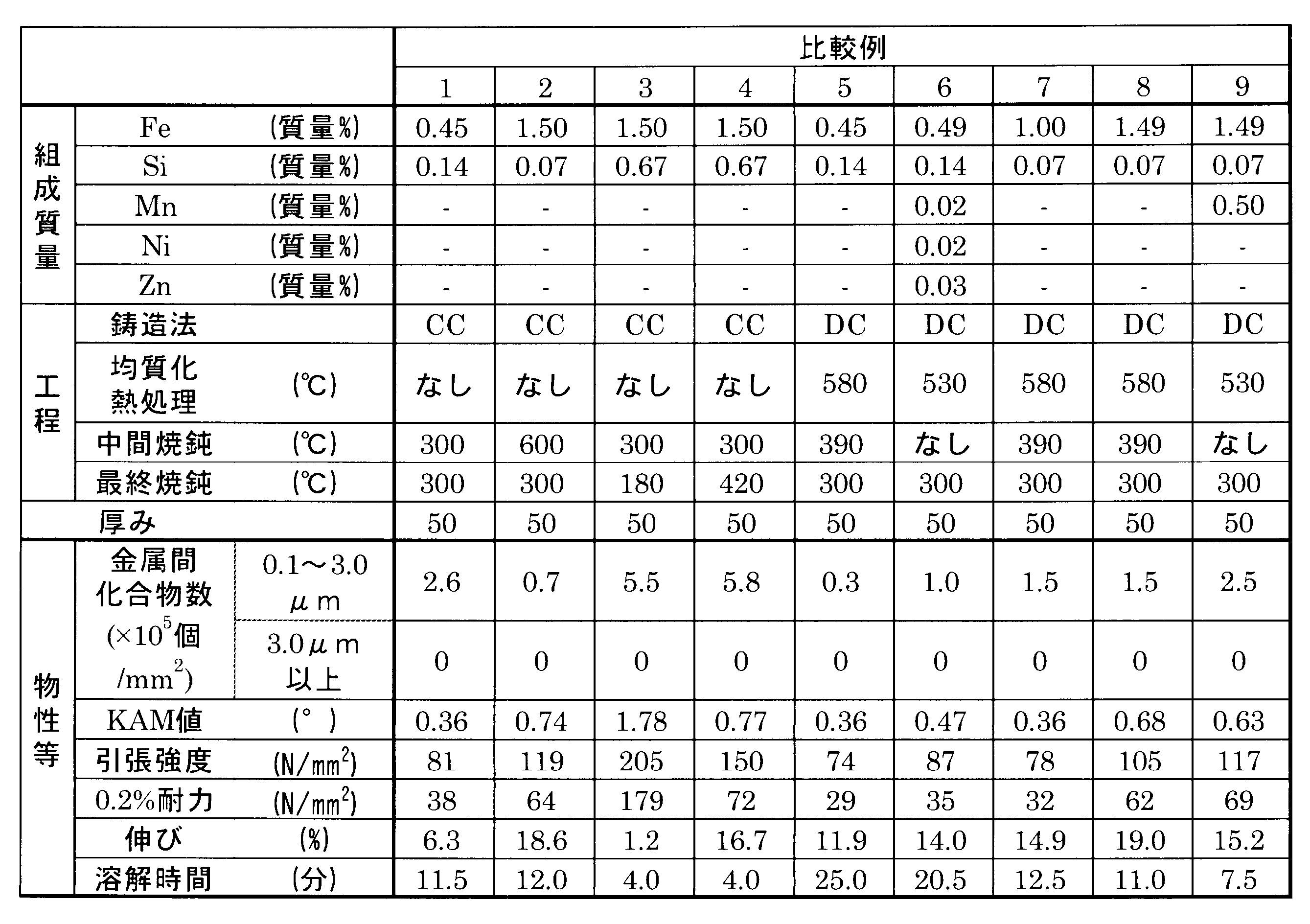
- Examples 1 to 8, Comparative Examples 1 to 4 Aluminum alloys having the respective compositions shown in Tables 1 and 2 below were melted, and after the molten metal was subjected to degassing and inclusion treatment, a cast plate having a thickness of 7 mm was obtained by CC casting. The obtained cast plate was cold-rolled to a thickness of 1 mm, and then subjected to intermediate annealing at the temperatures shown in Tables 1 and 2. After the intermediate annealing, cold rolling was further performed to obtain a cold rolled foil having a thickness of 50 ⁇ m. The obtained cold-rolled foil was subjected to final annealing at the temperature shown in Tables 1 and 2 for 2 hours. The final thickness is as shown in Tables 1 and 2. Each physical property of the obtained aluminum alloy foil was measured by the methods described above. The results are shown in Tables 1 and 2.
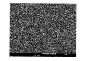
- Example 1 Example 1
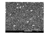
- FIG. 2 Comparative Example 7
- Example 1 Example 1
- Comparative Example 7 show composition images taken at the time of measuring the number of intermetallic compounds in Example 1 and Comparative Example 7.
- Example 1 a large number of fine intermetallic compounds of 0.1 ⁇ m to 3.0 ⁇ m are present.
- Comparative Example 7 it is clear that there are few fine intermetallic compounds of 0.1 ⁇ m to 3.0 ⁇ m.
Landscapes
- Chemical & Material Sciences (AREA)
- Engineering & Computer Science (AREA)
- Mechanical Engineering (AREA)
- Materials Engineering (AREA)
- Metallurgy (AREA)
- Organic Chemistry (AREA)
- Physics & Mathematics (AREA)
- Thermal Sciences (AREA)
- Crystallography & Structural Chemistry (AREA)
- Microelectronics & Electronic Packaging (AREA)
- Metal Rolling (AREA)
- Parts Printed On Printed Circuit Boards (AREA)
Abstract
Description
すなわち、本発明は以下の特徴を備える。
[3]少なくとも一層以上の被着体と、[1]又は[2]に記載のアルミニウム合金箔とを積層してなる、アルミニウム積層体。
[5]鋳造方法が双ロール式連続鋳造である、[4]に記載のアルミニウム合金箔の製造方法。
[6]中間焼鈍工程を含み、均質化熱処理工程及び熱間圧延工程を含まない、[4]又は[5]に記載のアルミニウム合金箔の製造方法。
本発明に係るアルミニウム合金箔は、所定量の鉄(Fe)、及び珪素(Si)を含み、残部はアルミニウム(Al)と不可避不純物を含む箔である。
本発明のアルミニウム合金箔は、鉄(Fe)を0.5質量%以上1.8質量%未満含む。鉄含有量が0.5質量%より少ないと、金属間化合物が少なく十分な化学溶解性が得られず、また最終焼鈍後の強度も不足する傾向が生じる。一方、鉄含有量が1.8質量%を超えると、鋳造時の初晶がAlからAl-Fe系化合物となり、鋳造欠陥や圧延性の低下を招く恐れがあり、また強度、伸びにも悪影響を及ぼす。
鉄含有量のより好ましい範囲は、0.8質量%以上1.6%未満である。上記範囲内であると化学溶解性、強度に優れたアルミニウム合金箔を安定して製造できる。
本発明のアルミニウム合金箔は珪素(Si)を1.5質量%未満含む。
珪素の添加は、Al-Fe系、Al-Fe-Si系化合物の晶析出を促進する。珪素含有量が増えることで化合物サイズは大きくなり、その数も増大する。1.5質量%以上になると晶出物が粗大になり、CC鋳造時に中心線偏析等欠陥が生じやすくなる。
本発明に係るアルミニウム合金箔を構成する成分の残部は、アルミニウムと不可避不純物からなる。この不可避不純物とは、アルミニウム合金箔の製造時に不可避的に混入した元素をいう。この不可避不純物は、本発明におけるアルミニウム合金箔の特性に影響を与えない範囲で含んでもよい。
本発明のアルミニウム合金箔は上記組成を備えるため、高価な添加元素を含まず、また化学溶解した際の廃液の処理コストを低減することができる。
本アルミニウム合金箔の断面に存在する円相当径0.1μmを超え、かつ3.0μm未満の金属間化合物の単位面積当たりの個数は、3.0×10⁵個/mm2以上である。上記範囲内であると金属間化合物を微細に数多く分散させることで、高い化学溶解性と高強度化が可能である。
本発明におけるKAM値とは、アルミニウム合金箔表面を観察面として、EBSD(電子線後方散乱回折)法により、指定のステップサイズ(0.6μm間隔)で配置された電子線照射スポットについて、隣接するスポット間の結晶方位差をすべて測定し(Nearest Neighbor=1st)、方位差5°未満(Maximum misorientation=5°)の測定値を抽出し、測定視野においてその平均値を求めたものに相当する。
本発明では、KAM値を適切な範囲に制御することで、優れた強度、伸びが得られることを見出した。このKAM値は、0.8°以上1.4°未満がよい。KAM値が0.8°より小さい状態は、回復、再結晶が進行した歪の少ない状態であるので、十分な強度が得られない傾向がある。KAM値が1.4°以上の状態は、歪が多く残存した状態であり、十分な伸びが得られない傾向がある。
KAM値のより好ましい範囲は0.9°以上1.3°未満である。上記範囲内であると、より強度、伸びに優れたアルミニウム合金箔を製造できる。
次に、本発明にかかるアルミニウム合金箔の製造方法について説明する。
本発明にかかるアルミニウム合金箔の製造方法は、前記組成範囲になるようにアルミニウム母合金を調製し、加熱してアルミニウム合金溶湯を作製する工程、前記アルミニウム合金溶湯を100℃/秒以上の冷却速度で鋳造して鋳塊を作製する工程、前記鋳塊を冷間圧延して箔にする工程、及び400℃以下、好ましくは200~400℃程度で最終焼鈍(FA)する工程を含む構成とした製造方法である。
本発明のアルミニウム合金箔は、含有する金属間化合物を微細分散させることが重要であり、鋳造冷却速度が約10℃/秒の半連続鋳造(DC(Direct Chill)鋳造)では難しい。
本発明にかかるアルミニウム合金箔の製造方法における、鋳造時の冷却速度は100℃/秒以上である。上記範囲内とすることにより、アルミニウム母相中に金属間化合物を微細に分散させることが出来るため、FA時の再結晶を抑制する事ができる。そのため、アルミニウム合金箔の強度、伸びを向上させることができる。また化学溶解の起点となる金属間化合物を微細に分散させることが出来るため配線基板に用いられた際にエッチング速度を向上させることが出来る。
本発明にかかるアルミニウム合金箔の製造方法においては、均質化熱処理工程を含まないことが好ましい。均質化熱処理工程を行うと、高い冷却速度を有する鋳造工程により過飽和固溶した添加元素が析出し、組織の粗大化を招くため、十分な高強度、伸び及び化学溶解性を兼ね備えるという、この発明の特徴を発揮しにくくなるおそれがある。
本発明にかかるアルミニウム合金箔の製造方法においては、熱間圧延工程を含まないことが好ましい。熱間圧延工程を行うと、高い冷却速度を有する鋳造工程により過飽和固溶した添加元素が析出し、組織の粗大化を招き、十分な高強度、伸び及び化学溶解性を兼ね備えるという、この発明の特徴を発揮しにくくなるおそれがある。
本発明にかかるアルミニウム合金箔の製造方法においては、中間焼鈍工程を含むことが好ましい。中間焼鈍工程はあっても無くてもよいが、圧延性の改善の目的で、アルミニウム合金箔の特性に影響が出ない範囲で行うことが好ましい。一例としては、空気雰囲気中で250℃以上550℃以下の温度で、1時間以上20時間以下行われる。
本発明にかかるアルミニウム合金箔の製造方法においては、最終焼鈍工程を含む。最終焼鈍工程は、例えば、空気雰囲気又は不活性ガス雰囲気中で、400℃以下で行われる。最終焼鈍温度が200℃未満の場合、圧延油の除去が不十分であり、またKAM値が1.4°より大きくなることが多い。最終焼鈍温度が400℃を超える場合、組織の粗大化による化学溶解性の悪化が懸念され、またKAM値が0.8°より小さくなることが多い。最終焼鈍は好ましくは200℃以上400℃以下、より好ましくは275℃以上400℃以下、1時間以上60時間以下である。これらの条件を満たす場合、得られるアルミニウム合金箔は、圧延油の除去が十分であり、前記に示したKAM値の範囲に制御可能であり、十分な強度、伸びが得られる。
<強度、0.2%耐力、伸び>
本発明にかかるアルミニウム合金箔は、圧延方向への引張強度が120N/mm2以上が好ましく、0.2%耐力が80N/mm2以上が好ましく、厚さ50μmにおける圧延方向への伸びが12.0%以上であることが好ましい。引張強度や0.2%耐力が上記範囲であると、プリント配線基板の製造工程において十分な作業性を確保できる。
ところで、本明細書において単に「耐力」と記載した場合は、「0.2%耐力」を指す。
アルミニウム合金箔の厚みは特に限定されないが、7μm以上100μm未満が好ましい。より好ましくは9μm以上50μm以下である。上記範囲であれば、プリント配線基板用として好適に採用できる。
7μm未満だとプリント配線基板の製造工程における作業性が悪化する傾向があり、100μm以上であればエッチング時の溶解時間が長くなりプリント配線基板用として不適となる傾向が生じる。
本発明にかかるアルミニウム合金箔は、その少なくとも一方の面に少なくとも一層以上の被着体を積層し、アルミニウム積層体とする事ができる。
上記被着体は可撓性を有するものでも、有さないものでもよく、例えば、ポリエチレン、ポリプロピレン、ポリエステル、ポリカーボネート、ポリイミド、ポリアミド等の樹脂フィルム、又は紙フェノール樹脂板、ガラスエポキシ板等が好適に用いられる。
また、前記積層に前もって、アルミニウム合金箔の表面を粗化したり、洗浄を行ったり、コーティング等を行ってもよい。
前記積層体のアルミニウム合金箔の表面に所望の配線形状となるようにレジストインキをパターン状に印刷し、次にエッチング液に浸漬してレジストインキが印刷されていない部分を溶解させた後、必要に応じてレジストを剥離することにより、アルミニウム合金箔を配線パターンに形成しプリント配線基板とすることができる。
印刷方法は公知のものを用いる事ができ、例えばグラビア印刷やスクリーン印刷等である。
上記エッチング液は、公知のものを用いる事ができ、酸性、アルカリ性等適宜採用でき、例えば水酸化ナトリウム(苛性ソーダ)水溶液や塩酸、塩化第二鉄液、塩化銅液、過酸化水素等、あるいはそれらの混合液が挙げられる。
[金属間化合物個数]
アルミニウム合金箔断面(ND-RD断面)をクロスセクションポリッシャ(日本電子(株)製SM-09010)により平滑に加工した後、電界放出形走査電子顕微鏡(日本電子(株)製JSM-7200F)により倍率2500倍で観察した。金属間化合物を観やすくするために反射電子像(組成像)で撮影した。金属間化合物のサイズ・個数は画像解析・計測ソフトウェアWinROOF2018(三谷商事(株):Version4.7.5)を使って評価した。解析ソフト内の画像処理でコントラスト・明るさを調整し、金属間化合物を明確にする。その後、単一しきい値による2値化で、アルミニウム合金箔断面の金属間化合物部分のデータのみを抽出できるように2値化処理した。2値化処理された金属間化合物部分で円相当径0.1μm以下の部分を削除するようにデータ処理し、残された円相当径0.1μmを超える部分で、3.0μm未満のものの個数、及び3.0μm以上のものの個数を計測し、単位面積当たりの金属間化合物の個数を算出した。ランダムに5視野で撮影し、その平均値を求めた。
アルミニウム合金箔表面のKAM値は、EBSD分析装置((株)TSLソリューションズVelocity)を備えた電界放出形走査電子顕微鏡(日本電子(株)製JSM-7200F)を使用して、倍率300倍、300μm×300μmの視野でステップサイズ0.6μmとしてEBSD測定を行い、その測定結果より、解析ソフトウェアOIM Analysis 8((株)TSLソリューションズ)によりNearest Neighbor = 1st、Maximum misorientation=5°で算出した。前処理としてアルミニウム合金箔表面は電解研磨で鏡面加工した。ランダムに3視野で測定し、その平均値を求めた。
FA後のアルミニウム合金箔を幅15mm、長さ200mmの短冊試験片に切り出し、(株)東洋精機製作所製のストログラフVES5Dで引張試験した。チャック間距離100mm、引張速度10mm/minとし、引張強度、耐力、伸びのデータを得た。試験は3回実施し、その平均値を算出した。引張試験の方向は圧延方向に合わせた。
アルミニウム合金箔の片側表面のみ1×1cm露出するようにマスキングテープを貼り、塩酸8質量%、塩化アルミニウム4質量%となるよう作製した40℃のエッチング液に含浸し、アルミニウム合金箔露出部が完全に溶解するまでの時間を測定した。
下記の表1、2に示す各組成からなるアルミニウム合金を溶解し、その溶湯を脱ガス・脱介在物処理した後にCC鋳造で厚み7mmの鋳造板を得た。得られた鋳造板に冷間圧延を行い厚さ1mmにした後、表1、2に記載の温度で中間焼鈍を行った。中間焼鈍の後さらに冷間圧延を行い、厚み50μmの冷間圧延箔を得た。得られた前記冷間圧延箔に表1、2に記載の温度で2時間保持する最終焼鈍を施した。最終厚みは表1、2記載の通りとする。得られたアルミニウム合金箔の各物性等を前記した方法で測定した。その結果を表1、2に示す。
下記の表2記載の組成でDC鋳造により鋳塊を得た。鋳塊を面削後、表2記載の温度で均質化熱処理を行った後、熱間圧延により厚み7mmの板とした。その後は上記実施例と同様に冷間圧延、中間焼鈍、最終焼鈍を表2記載の条件で実施した。最終厚みは表2記載の通りとする。得られたアルミニウム合金箔の各物性等を前記した方法で測定した。その結果を表2に示す。
この結果から、実施例1では、0.1μm~3.0μmの細かい金属間化合物が多数存在していることが明らかである。一方、比較例7では、0.1μm~3.0μmの細かい金属間化合物は少ないことが明らかである。

Claims (6)
- アルミニウム合金箔であって、
(1)鉄含有量が0.5質量%以上1.8質量%未満、珪素含有量が1.5質量%未満、残部がアルミニウムと不可避不純物とからなり、
(2)前記アルミニウム合金箔断面中に円相当径が0.1μmを超え、かつ3.0μm未満の金属間化合物を3.0×10⁵個/mm2以上含み、
(3)前記アルミニウム合金箔表面を観察面として、EBSD(電子線後方散乱回折)法により、ステップサイズ:0.6μm、Nearest neighbor:1st、Maximum Orientation:5°の条件で測定したKAM(Kernel Average Misorientation)値が0.8°以上1.4°未満であるアルミニウム合金箔。 - 圧延方向への引張強度が120N/mm2以上、0.2%耐力が80N/mm2以上であり、
厚さ50μmにおける圧延方向への伸びが12.0%以上である、請求項1に記載のアルミニウム合金箔。 - 少なくとも一層以上の被着体と、請求項1又は2に記載のアルミニウム合金箔とを積層してなる、アルミニウム積層体。
- 鉄含有量が0.5質量%以上1.8質量%未満、珪素含有量が1.5質量%未満、残部がアルミニウムと不可避不純物とからなるアルミニウム合金の溶湯を、
100℃/秒以上の冷却速度で鋳造することにより、アルミニウム合金の鋳塊を得る工程と、
前記鋳塊を冷間圧延することにより、アルミニウム合金箔の冷間圧延箔を得る工程と、
前記冷間圧延箔を400℃以下の温度で焼鈍する工程を備える、アルミニウム合金箔の製造方法。 - 鋳造方法が双ロール式連続鋳造である、請求項4に記載のアルミニウム合金箔の製造方法。
- 中間焼鈍工程を含み、均質化熱処理工程及び熱間圧延工程を含まない、請求項4又は5に記載のアルミニウム合金箔の製造方法。
Priority Applications (2)
| Application Number | Priority Date | Filing Date | Title |
|---|---|---|---|
| CN202280021815.0A CN116997667A (zh) | 2021-03-18 | 2022-03-09 | 铝合金箔、铝层叠体和铝合金箔的制造方法 |
| KR1020237034815A KR20230157418A (ko) | 2021-03-18 | 2022-03-09 | 알루미늄 합금박, 알루미늄 적층체, 및 알루미늄 합금박의 제조 방법 |
Applications Claiming Priority (2)
| Application Number | Priority Date | Filing Date | Title |
|---|---|---|---|
| JP2021044731A JP7697801B2 (ja) | 2021-03-18 | 2021-03-18 | アルミニウム合金箔、アルミニウム積層体、及びアルミニウム合金箔の製造方法 |
| JP2021-044731 | 2021-03-18 |
Publications (1)
| Publication Number | Publication Date |
|---|---|
| WO2022196489A1 true WO2022196489A1 (ja) | 2022-09-22 |
Family
ID=83320593
Family Applications (1)
| Application Number | Title | Priority Date | Filing Date |
|---|---|---|---|
| PCT/JP2022/010291 Ceased WO2022196489A1 (ja) | 2021-03-18 | 2022-03-09 | アルミニウム合金箔、アルミニウム積層体、及びアルミニウム合金箔の製造方法 |
Country Status (4)
| Country | Link |
|---|---|
| JP (1) | JP7697801B2 (ja) |
| KR (1) | KR20230157418A (ja) |
| CN (1) | CN116997667A (ja) |
| WO (1) | WO2022196489A1 (ja) |
Cited By (2)
| Publication number | Priority date | Publication date | Assignee | Title |
|---|---|---|---|---|
| WO2025023084A1 (ja) * | 2023-07-27 | 2025-01-30 | 東洋アルミニウム株式会社 | アルミニウム粗化箔及びその製造方法、並びに、積層体 |
| JP2025110397A (ja) * | 2024-01-15 | 2025-07-28 | チナルコ マテリアルズ アプリケーション リサーチ インスティテューション カンパニー,リミテッド | アルミ箔材料及びその製造方法 |
Families Citing this family (2)
| Publication number | Priority date | Publication date | Assignee | Title |
|---|---|---|---|---|
| JP2024039404A (ja) | 2022-09-09 | 2024-03-22 | キヤノン株式会社 | 記録装置とその制御方法 |
| CN119340116A (zh) * | 2023-12-28 | 2025-01-21 | 湖北海成电子有限公司 | 一种生产杂质少的固态铝电解电容器生产方法 |
Citations (4)
| Publication number | Priority date | Publication date | Assignee | Title |
|---|---|---|---|---|
| JPS6434548A (en) * | 1987-07-30 | 1989-02-06 | Furukawa Aluminium | Production of high strength aluminum foil |
| JP2004027353A (ja) * | 2002-05-07 | 2004-01-29 | Nippon Foil Mfg Co Ltd | アルミニウム合金箔及びその製造方法並びにアルミニウム積層体 |
| WO2013018165A1 (ja) * | 2011-07-29 | 2013-02-07 | 古河スカイ株式会社 | 電極集電体用アルミニウム合金箔及びその製造方法 |
| JP2016041835A (ja) * | 2014-08-14 | 2016-03-31 | 三菱アルミニウム株式会社 | アルミニウム合金箔およびその製造方法 |
Family Cites Families (5)
| Publication number | Priority date | Publication date | Assignee | Title |
|---|---|---|---|---|
| JP2001152270A (ja) | 1999-11-25 | 2001-06-05 | Mitsubishi Alum Co Ltd | 印刷回路用アルミニウム合金箔 |
| US6663729B2 (en) * | 2001-02-13 | 2003-12-16 | Alcan International Limited | Production of aluminum alloy foils having high strength and good rollability |
| JP2012149289A (ja) | 2011-01-18 | 2012-08-09 | Mitsubishi Alum Co Ltd | 印刷回路用アルミニウム箔 |
| JP5848672B2 (ja) * | 2011-06-07 | 2016-01-27 | 株式会社Uacj | アルミニウム合金箔の製造方法およびアルミニウム合金箔 |
| JPWO2017135108A1 (ja) * | 2016-02-01 | 2018-12-20 | 株式会社Uacj | アルミニウム合金箔およびその製造方法 |
-
2021
- 2021-03-18 JP JP2021044731A patent/JP7697801B2/ja active Active
-
2022
- 2022-03-09 WO PCT/JP2022/010291 patent/WO2022196489A1/ja not_active Ceased
- 2022-03-09 KR KR1020237034815A patent/KR20230157418A/ko active Pending
- 2022-03-09 CN CN202280021815.0A patent/CN116997667A/zh active Pending
Patent Citations (4)
| Publication number | Priority date | Publication date | Assignee | Title |
|---|---|---|---|---|
| JPS6434548A (en) * | 1987-07-30 | 1989-02-06 | Furukawa Aluminium | Production of high strength aluminum foil |
| JP2004027353A (ja) * | 2002-05-07 | 2004-01-29 | Nippon Foil Mfg Co Ltd | アルミニウム合金箔及びその製造方法並びにアルミニウム積層体 |
| WO2013018165A1 (ja) * | 2011-07-29 | 2013-02-07 | 古河スカイ株式会社 | 電極集電体用アルミニウム合金箔及びその製造方法 |
| JP2016041835A (ja) * | 2014-08-14 | 2016-03-31 | 三菱アルミニウム株式会社 | アルミニウム合金箔およびその製造方法 |
Cited By (2)
| Publication number | Priority date | Publication date | Assignee | Title |
|---|---|---|---|---|
| WO2025023084A1 (ja) * | 2023-07-27 | 2025-01-30 | 東洋アルミニウム株式会社 | アルミニウム粗化箔及びその製造方法、並びに、積層体 |
| JP2025110397A (ja) * | 2024-01-15 | 2025-07-28 | チナルコ マテリアルズ アプリケーション リサーチ インスティテューション カンパニー,リミテッド | アルミ箔材料及びその製造方法 |
Also Published As
| Publication number | Publication date |
|---|---|
| CN116997667A (zh) | 2023-11-03 |
| KR20230157418A (ko) | 2023-11-16 |
| JP7697801B2 (ja) | 2025-06-24 |
| JP2022143934A (ja) | 2022-10-03 |
Similar Documents
| Publication | Publication Date | Title |
|---|---|---|
| JP7697801B2 (ja) | アルミニウム合金箔、アルミニウム積層体、及びアルミニウム合金箔の製造方法 | |
| KR102872450B1 (ko) | 순구리판 | |
| KR100966287B1 (ko) | 고강도 및 우수한 굽힘 가공성을 갖춘 구리 합금 및 구리합금판의 제조 방법 | |
| JP2898627B2 (ja) | 銅合金箔 | |
| CN100564559C (zh) | 电子材料用Cu-Ni-Si-Co-Cr系铜合金及其制造方法 | |
| US4802935A (en) | Substrate for a lithographic printing plate | |
| US20020155021A1 (en) | Copper-alloy foil to be used for laminate sheet | |
| US20230183843A1 (en) | Magnesium alloy, magnesium alloy plate, magnesium alloy bar, manufacturing methods thereof, and magnesium alloy member | |
| JP2011184775A (ja) | 高強度高耐熱性銅合金材 | |
| JP2013237926A (ja) | 陽極酸化処理後の表面品質に優れたアルミニウム合金板およびその製造方法 | |
| KR20170130517A (ko) | 방열 부품용 구리 합금판 및 방열 부품 | |
| KR20240124905A (ko) | 구리 합금 판재 및 구리 합금 판재를 사용하여 제작된 드로잉 가공 부품 | |
| KR102220851B1 (ko) | 보호막 형성용 스퍼터링 타깃 및 적층 배선막 | |
| JPS64456B2 (ja) | ||
| JP6105815B2 (ja) | アルミニウム箔、これを用いた電子部品配線基板、およびアルミニウム箔の製造方法 | |
| JP6857535B2 (ja) | 成形性、曲げ加工性および耐デント性に優れた高強度アルミニウム合金板及びその製造方法 | |
| JP2009084593A (ja) | Cu−Cr−Si系合金箔 | |
| JPH11264037A (ja) | 銅合金箔 | |
| JPH0978168A (ja) | アルミニウム合金板 | |
| KR20240164910A (ko) | 알루미늄 합금박 및 그 제조 방법 | |
| CN104812920B (zh) | 溅射靶用铜合金制热轧板及溅射靶 | |
| JPH1171622A (ja) | 成形用アルミニウム合金板およびその製造方法 | |
| JP4937628B2 (ja) | 熱間加工性に優れた銅合金 | |
| KR101988794B1 (ko) | 내식성이 우수한 마그네슘 합금 판재 및 그 제조방법 | |
| JP4164206B2 (ja) | 高温焼鈍時の再結晶粒微細化に優れた高強度高成形性アルミニウム合金板 |
Legal Events
| Date | Code | Title | Description |
|---|---|---|---|
| 121 | Ep: the epo has been informed by wipo that ep was designated in this application |
Ref document number: 22771240 Country of ref document: EP Kind code of ref document: A1 |
|
| WWE | Wipo information: entry into national phase |
Ref document number: 202280021815.0 Country of ref document: CN |
|
| ENP | Entry into the national phase |
Ref document number: 20237034815 Country of ref document: KR Kind code of ref document: A |
|
| WWE | Wipo information: entry into national phase |
Ref document number: 1020237034815 Country of ref document: KR |
|
| NENP | Non-entry into the national phase |
Ref country code: DE |
|
| 122 | Ep: pct application non-entry in european phase |
Ref document number: 22771240 Country of ref document: EP Kind code of ref document: A1 |