WO2022196455A1 - Dispositif de commande électronique - Google Patents
Dispositif de commande électronique Download PDFInfo
- Publication number
- WO2022196455A1 WO2022196455A1 PCT/JP2022/010093 JP2022010093W WO2022196455A1 WO 2022196455 A1 WO2022196455 A1 WO 2022196455A1 JP 2022010093 W JP2022010093 W JP 2022010093W WO 2022196455 A1 WO2022196455 A1 WO 2022196455A1
- Authority
- WO
- WIPO (PCT)
- Prior art keywords
- substrate
- noise
- region
- circuit
- fastening member
- Prior art date
Links
- 239000000758 substrate Substances 0.000 claims abstract description 43
- 239000003990 capacitor Substances 0.000 claims description 7
- 238000004804 winding Methods 0.000 description 7
- 238000004891 communication Methods 0.000 description 6
- 238000010586 diagram Methods 0.000 description 5
- 239000000853 adhesive Substances 0.000 description 4
- 230000001070 adhesive effect Effects 0.000 description 4
- 230000002093 peripheral effect Effects 0.000 description 4
- 238000003780 insertion Methods 0.000 description 3
- 230000037431 insertion Effects 0.000 description 3
- XAGFODPZIPBFFR-UHFFFAOYSA-N aluminium Chemical compound [Al] XAGFODPZIPBFFR-UHFFFAOYSA-N 0.000 description 2
- 229910052782 aluminium Inorganic materials 0.000 description 2
- 238000006243 chemical reaction Methods 0.000 description 2
- 239000000428 dust Substances 0.000 description 2
- 230000000694 effects Effects 0.000 description 2
- 238000012986 modification Methods 0.000 description 2
- 230000004048 modification Effects 0.000 description 2
- XLYOFNOQVPJJNP-UHFFFAOYSA-N water Substances O XLYOFNOQVPJJNP-UHFFFAOYSA-N 0.000 description 2
- 230000005540 biological transmission Effects 0.000 description 1
- 230000007423 decrease Effects 0.000 description 1
- 238000001514 detection method Methods 0.000 description 1
- 238000006073 displacement reaction Methods 0.000 description 1
- 238000009434 installation Methods 0.000 description 1
- 230000010354 integration Effects 0.000 description 1
- 239000000463 material Substances 0.000 description 1
- 238000010397 one-hybrid screening Methods 0.000 description 1
- 230000003071 parasitic effect Effects 0.000 description 1
- 239000011347 resin Substances 0.000 description 1
- 229920005989 resin Polymers 0.000 description 1
Images


Classifications
-
- H—ELECTRICITY
- H02—GENERATION; CONVERSION OR DISTRIBUTION OF ELECTRIC POWER
- H02M—APPARATUS FOR CONVERSION BETWEEN AC AND AC, BETWEEN AC AND DC, OR BETWEEN DC AND DC, AND FOR USE WITH MAINS OR SIMILAR POWER SUPPLY SYSTEMS; CONVERSION OF DC OR AC INPUT POWER INTO SURGE OUTPUT POWER; CONTROL OR REGULATION THEREOF
- H02M7/00—Conversion of ac power input into dc power output; Conversion of dc power input into ac power output
- H02M7/42—Conversion of dc power input into ac power output without possibility of reversal
- H02M7/44—Conversion of dc power input into ac power output without possibility of reversal by static converters
- H02M7/48—Conversion of dc power input into ac power output without possibility of reversal by static converters using discharge tubes with control electrode or semiconductor devices with control electrode
-
- H—ELECTRICITY
- H05—ELECTRIC TECHNIQUES NOT OTHERWISE PROVIDED FOR
- H05K—PRINTED CIRCUITS; CASINGS OR CONSTRUCTIONAL DETAILS OF ELECTRIC APPARATUS; MANUFACTURE OF ASSEMBLAGES OF ELECTRICAL COMPONENTS
- H05K7/00—Constructional details common to different types of electric apparatus
- H05K7/14—Mounting supporting structure in casing or on frame or rack
Definitions
- the present disclosure relates to an electronic control device.
- an electronic control device having an inverter or the like is known.
- a substrate on which switching elements constituting an inverter section are mounted is screwed to a housing by four substrate fixing screws.
- An object of the present disclosure is to provide an electronic control device that can be miniaturized and reduce noise.
- the electronic control device of the present disclosure includes a substrate, a housing, and three fastening members.
- a noise generating element is mounted on the substrate.
- a substrate is fixed to the housing.
- the fastening member fastens the substrate to the housing.
- a noise generation circuit internal fastening member which is one fastening member, is arranged in a noise generation region where a noise generation element is mounted, and is electrically connected to the housing.
- FIG. 1 is a schematic configuration diagram showing a steering system according to the first embodiment
- FIG. 2 is a side view showing the driving device according to the first embodiment
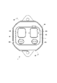
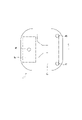
- 3 is a view in the direction of arrow III in FIG. 2
- FIG. 4 is a cross-sectional view taken along line IV-IV of FIG.
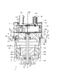
- FIG. 5 is a side view showing the ECU with the cover removed according to the first embodiment
- FIG. 6 is a perspective view showing the drive device with the cover removed according to the first embodiment
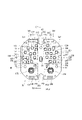
- FIG. 7 is a plan view showing the motor-side surface of the main board according to the first embodiment
- FIG. 1 is a schematic configuration diagram showing a steering system according to the first embodiment
- FIG. 2 is a side view showing the driving device according to the first embodiment
- 3 is a view in the direction of arrow III in FIG. 2
- FIG. 4 is a cross-sectional view taken along line IV-IV of FIG.
- FIG. 5 is a side view showing the ECU with the cover removed according to the first embodiment
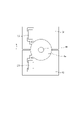
- FIG. 8 is a schematic diagram showing the ground pattern of the main substrate according to the first embodiment
- FIG. 9 is a plan view showing the arrangement of fastening members according to the first embodiment
- FIG. 10 is an explanatory diagram for explaining the noise feedback loop according to the first embodiment
- FIG. 11 is a schematic diagram showing the ground pattern of the main substrate according to the second embodiment
- FIG. 12 is a plan view showing the arrangement of fastening members according to the third embodiment
- FIG. 13 is a plan view showing the arrangement of fastening members according to a reference example
- FIG. 14 is an explanatory diagram for explaining a noise feedback loop according to the reference example.
- FIGS. 1 to 10 An electronic control unit according to a first embodiment is shown in FIGS. 1 to 10.
- FIG. 1 An electronic control unit according to a first embodiment is shown in FIGS. 1 to 10.
- the driving device 1 includes a motor 80 and an ECU 10 as an electronic control device, and is applied to an electric power steering device 8 which is a steering device for assisting steering operation of a vehicle.
- FIG. 1 shows the overall configuration of a steering system 90 including an electric power steering device 8.
- the steering system 90 includes a steering wheel 91 that is a steering member, a steering shaft 92, a pinion gear 96, a rack shaft 97, wheels 98, an electric power steering device 8, and the like.
- a steering wheel 91 is connected to a steering shaft 92 .
- the steering shaft 92 is provided with a torque sensor 93 that detects steering torque.
- the torque sensor 93 is internally divided into two systems, and each detection value is input to the corresponding connectors 156 and 256 .
- a pinion gear 96 is provided at the tip of the steering shaft 92 .
- the pinion gear 96 meshes with the rack shaft 97 .
- a pair of wheels 98 are connected to both ends of the rack shaft 97 via tie rods or the like.
- the electric power steering device 8 includes the driving device 1 and a speed reduction gear 89 as a power transmission unit that reduces the speed of rotation of the motor 80 and transmits it to the rack shaft 97 .
- the electric power steering device 8 of the present embodiment is a so-called "rack assist type", but it may be a so-called “column assist type” that transmits the rotation of the motor 80 to the steering shaft 92, or the like.
- the motor 80 is a three-phase brushless motor.
- the motor 80 outputs part or all of the torque required for steering, and is driven by being supplied with power from a battery (not shown) to rotate the reduction gear 89 forward and backward.
- Motor 80 has a first motor winding 180 and a second motor winding 280 .
- first system a combination of configurations related to energization control of the first motor winding 180
- second system a combination of configurations related to energization control of the second motor winding 280
- the configuration of the first system is mainly numbered in the 100s
- the configuration of the second system L2 is mainly numbered in the 200s. Numbers are assigned so that the digits are the same, and explanations are omitted as appropriate.
- the subscript "1" is added to the configuration related to the first system L1
- subscript "2" is added to the configuration related to the second system L2.
- the drive device 1 is integrally provided with the ECU 10 on one side in the axial direction of the motor 80, and is a so-called “machine-electrically integrated type", but the motor 80 and the ECU 10 may be provided separately.
- the ECU 10 is arranged coaxially with the axis Ax of the shaft 870 on the side opposite to the output shaft of the motor 80 .
- coaxial means that errors and deviations related to assembly and design are allowed, for example.
- the "mechanical and electrical integration" in the drive device 1 of the present embodiment is different from the motor 80 in which, for example, an approximately rectangular parallelepiped ECU is simply provided close to the motor 80 .
- the ECU 10 and the motor 80 can be efficiently arranged in a vehicle with limited installation space.
- the axial direction of the motor 80 will be regarded as the axial direction of the driving device 1, and will simply be referred to as the "axial direction".
- the motor 80 has a motor case 830, a motor frame 840, a stator 860, a rotor 865, and the like.
- the stator 860 is fixed to the motor case 830 and has the motor windings 180, 280 wound thereon.
- the rotor 865 is provided radially inside the stator 860 and is provided rotatably relative to the stator 860 .
- the shaft 870 is fitted into the rotor 865 and rotates together with the rotor 865 .
- Shaft 870 is rotatably supported by motor case 830 and motor frame 840 by bearings 871 and 872 .
- An end portion of the shaft 870 on the side of the ECU 10 is inserted through a shaft hole 849 formed in the motor frame 840 and exposed to the side of the ECU 10 .
- a magnet 875 is provided at the end of the shaft 870 on the side of the ECU 10 .
- the motor case 830 is formed in a substantially bottomed tubular shape consisting of a bottom portion 831 and a tubular portion 832, and the ECU 10 is provided on the opening side.
- a bearing 871 is provided on the bottom portion 831 .
- a stator 860 is fixed to the cylindrical portion 832 .
- the motor frame 840 has a frame portion 841, a heat sink 845, a connector connection portion 846, etc., and is made of a material with good thermal conductivity such as aluminum.
- the frame portion 841 is press-fitted radially inward of the motor case 830, and as a whole is within a projected area (hereinafter referred to as “motor silhouette” as appropriate) obtained by projecting the cylindrical portion 832 of the motor case 830 in the axial direction. It's settled.
- a flange portion 842 is formed on the outer circumference of the frame portion 841 and contacts a stepped portion 833 formed on the inner wall of the cylindrical portion 832 .
- An extension member connection portion 843 is formed outside the heat sink 845 of the frame portion 841 .
- the connector connecting portion 846 is erected substantially in the center of the side surface of the heat sink 845 from which the motor windings 180 and 280 are not taken out.
- the height of the connector connection portion 846 is higher than the heat sink 845 .
- the ECU 10 has a main board 31, a sub-board 32, power system connection parts 141, 241, signal system connection parts 146, 246, a connector unit 50, a cover 60, and the like.
- the main board 31 is fixed to a board fixing portion 847 formed on the end surface of the heat sink 845 with fastening members 45 to 47 .
- the sub-board 32 is fixed to the connector unit 50 .
- the substrates 31 and 32 are larger than the heat sink 845 when projected in the axial direction, and are formed to extend to the outside of the heat sink 845 .
- the main substrate 31 On the surface of the main substrate 31 on the side of the heat sink 845, switching elements and the like constituting an inverter are mounted, and are provided on the heat sink 845 so as to be capable of dissipating heat. Components such as an aluminum electrolytic capacitor are mounted on the surface of the main board 31 opposite to the heat sink 845 . The arrangement of components on the main board 31 will be described later.
- the main substrate 31 is formed with relief recesses 316 in order to avoid interference with the connector connecting portion 846 .
- the sub-board 32 On the sub-board 32, components such as choke coils and capacitors that make up the filter circuit, and communication drivers are mounted.
- the sub-board 32 is formed with a relief recess 326 for relief of a fixing portion 516 of the connector unit 50, which will be described later.
- the main board 31 and the sub-board 32 are connected by power system connection parts 141 and 241 and signal system connection parts 146 and 246 .
- the power connection components 141 and 241 are arranged on both sides of the relief recesses 316 and 326 along the same side in the outer area outside the area where various elements such as switching elements are mounted.
- the signal system connection components 146 and 246 are arranged along the side opposite to the power system connection components 141 and 241 in the outer area outside the area where various elements are mounted, with relief recesses 316 and 326 interposed therebetween. are placed on both sides.
- the connector unit 50 has a base portion 51, vehicle system connectors 152, 252, and steering system connectors 156, 256.
- the base portion 51 is formed in a substantially rectangular shape in plan view.
- a groove portion 511 is formed along the outer edge of the surface of the base portion 51 opposite to the motor 80 .
- a fixing portion 516 is formed on the base portion 51 .
- a through bolt 519 is inserted through the fixing portion 516 and screwed to the connector connection portion 846 of the motor frame 840 .
- the connector unit 50 is thereby fixed to the motor frame 840 .
- the connection position in the axial direction between the connector connecting portion 846 of the motor frame 840 and the fixing portion 516 of the connector unit 50 is between the main board 31 and the sub-board 32 .
- the connectors 152, 156, 252, 256 are formed with their frontage facing outward in the axial direction.
- the vehicle system connectors 152 and 252 are integrated with a power system connector connected to the vehicle power supply and ground, and a communication system connector connected to the vehicle communication network 99 (see FIG. 1) such as CAN (Controller Area Network). It is an all-in-one hybrid connector.
- the steering system connectors 156 and 256 are connected to the torque sensor 93 .
- the cover 60 is formed in a substantially cylindrical shape with a bottom, and accommodates the substrates 31 and 32, the heat sink 845 and the like inside.
- a substantially rectangular hole 61 is formed in the bottom of the cover 60 .
- Connectors 152 , 156 , 252 , 256 are inserted through the holes 61 .
- the end portion 611 of the hole portion 61 is bent inward.
- the end portion 611 is inserted into the groove portion 511 of the connector unit 50 coated with an adhesive member such as an adhesive. This prevents water droplets and dust from entering between the connector unit 50 and the cover 60 .
- the connector unit 50 does not fit into the motor silhouette.
- the expansion member 70 has a base portion 71, an annular convex portion 72, a cover insertion groove 73, a fixing portion 74, etc., and is integrally formed of resin or the like.
- the extension member 70 is formed in an annular shape as a whole, and is arranged on the ECU 10 side of the frame portion 841 of the motor frame 840 and radially outside the heat sink 845 .
- the heat sink 845 is formed on the inner peripheral side of the extension member 70 so as to protrude toward the ECU 10 side. At least part of the outer edge of the extension member 70 is located outside the motor silhouette.
- the annular convex portion 72 is provided on the motor 80 side surface of the base portion 71 so as to protrude along the inner peripheral surface, and is inserted into the cylindrical portion 832 of the motor case 830 .
- a cover insertion groove 73 is formed along the outer edge of the surface of the expansion member 70 opposite to the motor 80 .
- the opening-side end of the cover 60 is inserted into a cover insertion groove 73 coated with an adhesive member such as an adhesive.
- the fixing portion 74 is formed to protrude radially inward from the inner peripheral wall of the expansion member 70 .
- a collar is inserted into the fixed portion 74 and fixed to the frame portion 841 with a screw 79 .
- FIG. 7 shows the surface of the substrate 31 on the heat sink 845 side.
- the holes through which the fastening members 45 and the like are inserted are denoted by the reference numerals of the corresponding members.
- the electronic components related to the first system L1 and the electronic components related to the second system L2 are mounted on the board 31 in areas separated by a board center line C that divides the board 31 into two.
- a region in which electronic components related to the first system L1 are mounted is defined as a first system region RL1
- a region in which electronic components related to the second system L2 are mounted is defined as a second system region RL2.
- the area where the switching elements 121 to 126, the motor relays 127 to 129, the shunt resistors 131 to 133, and the power supply relays 111 and 112 of the first system L1 are mounted is the first power area Rp1, and the switching element 221 of the second system L2. 226, motor relays 227 to 229, shunt resistors 231 to 233, and power supply relays 211 and 212 are mounted as a second power region Rp2.
- a first control region Rc1 is a region where control components including the microcomputer 170 and the integrated circuit unit 175 of the first system L1 are mounted, and a control component including the microcomputer 270 and the integrated circuit unit 275 of the second system L2 is mounted.
- the microcomputers 170 and 270 are mounted on the surface of the substrate 31 on the connector unit 50 side.
- the heat sink 845 side and the connector unit 50 side are generally arranged with power regions Rp and control regions Rc on both sides, but they do not have to be exactly the same.
- the board 31 is screwed to the motor frame 840 by three fastening members 45-47.
- Fastening members 45 to 47 are electrically connected to motor frame 840 .
- the electric potential of the motor frame 840 is assumed to be "casing ground”.
- the fastening member 45 is arranged on the substrate centerline C and between the first power region Rp1 and the second power region Rp2. If the first power region Rp1 and the second power region Rp2 are regarded collectively as the power region Rp, it can be said that the fastening member 45 is arranged within the power region Rp.
- the fastening members 46, 47 are arranged outside the control regions Rc1, Rc2 and inside the connection points of the motor windings 180, 280 (that is, on the board centerline C side).
- the fastening members 46 and 47 are arranged line-symmetrically with respect to the center line C of the board.
- one fastening member 45 is arranged on the substrate center line C on the power region Rp side, and two fastening members 46 and 47 are arranged line-symmetrically outside the element mounting region on the control region Rc side. are placed. Thereby, the substrate 31 can be prevented from warping and can be properly fixed to the heat sink 845 .
- noise generated by the on/off operation of the switching elements 121 to 126 that make up the inverter circuit is transmitted through the parasitic capacitance PC formed between the main substrate 31 and the motor frame 840 and the fastening member 45. are fed back within the power regions Rp1 and Rp2.
- the noise shown by the dashed-dotted arrow in FIG. Feedback loop RT becomes relatively large.
- the fastening member 45 is arranged inside the power region Rp.
- the noise feedback loop RT can be made relatively small (see FIG. 10).
- a first ground pattern G1 relating to the first system L1 and a second ground pattern G2 relating to the second system L2 are separated at the substrate center line C.
- the ground pattern Gs where the fastening member 45 is arranged is connected to the housing ground via the fastening member 45 .
- the fastening ground pattern Gs is connected through the capacitor 139 to the first ground pattern G1 and through the capacitor 239 to the second ground pattern G2.
- the ECU 10 of this embodiment includes the main board 31, the motor frame 840, and the three fastening members 45-47.
- a noise generating element is mounted on the substrate 31 .
- the noise generating elements of this embodiment are the switching elements 121 to 126 and 221 to 226 that constitute the first inverter circuit 120 and the second inverter circuit.
- the main board 31 is fixed to the motor frame 840 .
- the fastening members 45 to 47 fasten the board 31 to the motor frame 840 .
- One fastening member 45 is arranged in the noise generation area where the noise generation element is mounted, and is electrically connected to the motor frame 840 .
- the circuit board 31 and the motor frame 840 are fastened at three points, so the number of parts can be reduced and the cycle time can be reduced compared to fastening at four or more points. Further, by providing one of the fastening members 45 to 47 in the noise generation circuit and electrically connecting it to the motor frame 840, the noise feedback loop can be shortened, thereby reducing noise.
- the noise generating elements are the switching elements 121 to 126 and 221 to 226 forming the inverter circuits 120 and 220, respectively.
- a noise generation region is a power region Rp in which switching elements 121 to 126 and 221 to 226 are mounted.
- the inverter circuit includes a first inverter circuit 120 and a second inverter circuit 220.
- the fastening member 45 includes a first power region Rp1 in which the first inverter circuit 120 is mounted and a second power region Rp1 in which the second inverter circuit 220 is mounted. It is arranged on the substrate center line C that separates the power region Rp2. As a result, the fastening member 45 can be shared by the noise feedback loops in the two inverter circuits 120 and 220 .
- Control parts including microcomputers 170, 270 for controlling the on/off operations of switching elements 121-126, 221-226 are arranged in separate areas from the first power area Rp1 and the second power area Rp2.
- the two fastening members 46 and 47 other than the fastening member 45 are arranged on both sides of the element mounting area where electronic components are mounted on the control area Rc side where the microcomputers 170 and 270 are arranged. . Thereby, distortion of the main substrate 31 can be reduced. Also, a relatively large mounting area can be secured for the control region Rc.
- the ground pattern is divided into two in the noise generation area.
- a fastening ground pattern Gs connected to the motor frame 840 by the fastening member 45 is connected via capacitors 139 and 239 to two ground patterns G1 and G2 divided in the noise generation area.
- the ECU 10 is an "electronic control device"
- the switching elements 121 to 126 and 221 to 226 are “noise generating elements”
- the motor frame 840 is a “casing”
- the fastening member 45 is a "fastening member within the noise generation area”.
- the integrated circuit units 175 and 275 correspond to the "control circuit component”
- the power region Rp corresponds to the "noise generation region”.
- FIG. 1 A second embodiment is shown in FIG.
- the substrate 31 has a common ground G3 for the first system and the second system. Therefore, the pattern where the fastening member 45 is arranged may be a common ground pattern, and the fastening member 45 connects the ground of the substrate 31 and the housing ground. This allows the capacitors 139 and 239 to be omitted. Even with such a configuration, the same effects as those of the above-described embodiment can be obtained.
- FIG. 1 A third embodiment is shown in FIG.
- the power regions Rp1 and Rp2 are regarded as "noise generation regions".
- the control region Rc is regarded as a "noise generation region”
- the fastening member 45 is arranged in the control region Rc1.
- the fastening member 45 is arranged on the substrate center line C between the first control region Rc1 and the second control region Rc2 (not shown in FIG. 12).
- the fastening members 46, 47 are arranged outside the power regions Rp1, Rp2.
- the noise generating elements are two integrated circuit units 175 and 275 that control the ON operation of the switching elements 121 to 126 and 221 to 226 mounted on the substrate 31, and the fastening member 45 includes two It is arranged inside the control region Rc in which the integrated circuit portions 175 and 275 are mounted.
- the feedback loop in the control region Rc can be shortened.
- a relatively large mounting area for the power area Rp can be secured.
- the same effects as those of the above-described embodiment can be obtained.
- the integrated circuit units 175 and 275 correspond to the "noise generation element", and the control region Rc corresponds to the "noise generation region”.
- the ECU is provided with two substrates.
- the sub-board may be omitted and electronic components may be mounted on one board.
- the two substrates are referred to as "main” and "sub” for convenience' sake in order to distinguish between them.
- the extension member is provided so that the control unit extends to the outside of the motor silhouette.
- the extension member may be omitted and the control unit may be housed in the motor silhouette.
- the three fastening members are electrically connected to the housing.
- the two fastening members other than the noise generating circuit internal fastening member may not be electrically connected to the housing.
- the board is fixed to the housing by three fastening members.
- an auxiliary member for fastening may be provided.
- the power connector connected to the vehicle power supply and ground and the communication connector connected to the vehicle communication network are integrated.
- the power connector and communication connector may be separate.
- the type and number of connectors can be set arbitrarily, and the frontages may be provided separately, or may be provided in an arbitrary combination.
- the connector frontage is provided separately for each system. In another embodiment, one frontage may be shared by two systems without dividing the connector frontage by system.
- the steering device is an electric power steering device.
- the steering device may be a steer-by-wire device
- the drive device may be used as a steering device for steering the wheels or as a reaction force device for applying a reaction force to the steering wheel.
- the driving device may be applied to devices other than the steering device.
- the present disclosure is by no means limited to the above embodiments, and can be implemented in various forms without departing from the scope of the present disclosure.
Abstract
Un dispositif de commande électronique (10) comprend : un substrat (31) ; un boîtier (840) ; et trois éléments de fixation (45-47). Des éléments de génération de bruit (121-126, 221-226, 175, 275) sont montés sur le substrat (31). Le substrat (31) est fixé au boîtier (840). Les éléments de fixation (45-47) fixent le substrat (31) au boîtier (840). Un élément de fixation de circuit de génération de bruit (45) qui est l'un des éléments de fixation est disposé dans une région de génération de bruit où les éléments de génération de bruit sont montés, et est électriquement connecté au boîtier.
Applications Claiming Priority (2)
| Application Number | Priority Date | Filing Date | Title |
|---|---|---|---|
| JP2021-045063 | 2021-03-18 | ||
| JP2021045063A JP2022144169A (ja) | 2021-03-18 | 2021-03-18 | 電子制御装置 |
Publications (1)
| Publication Number | Publication Date |
|---|---|
| WO2022196455A1 true WO2022196455A1 (fr) | 2022-09-22 |
Family
ID=83320485
Family Applications (1)
| Application Number | Title | Priority Date | Filing Date |
|---|---|---|---|
| PCT/JP2022/010093 WO2022196455A1 (fr) | 2021-03-18 | 2022-03-08 | Dispositif de commande électronique |
Country Status (2)
| Country | Link |
|---|---|
| JP (1) | JP2022144169A (fr) |
| WO (1) | WO2022196455A1 (fr) |
Citations (4)
| Publication number | Priority date | Publication date | Assignee | Title |
|---|---|---|---|---|
| JP2010073779A (ja) * | 2008-09-17 | 2010-04-02 | Aisin Aw Co Ltd | 電子回路装置 |
| JP2015006028A (ja) * | 2013-06-19 | 2015-01-08 | 三菱重工オートモーティブサーマルシステムズ株式会社 | インバータ一体型電動圧縮機 |
| JP2020018087A (ja) * | 2018-07-25 | 2020-01-30 | 株式会社デンソー | 駆動装置、および、これを用いた電動パワーステアリング装置 |
| WO2020241026A1 (fr) * | 2019-05-28 | 2020-12-03 | Kyb株式会社 | Machine électrique tournante et procédé de fabrication de machine électrique tournante |
-
2021
- 2021-03-18 JP JP2021045063A patent/JP2022144169A/ja active Pending
-
2022
- 2022-03-08 WO PCT/JP2022/010093 patent/WO2022196455A1/fr active Application Filing
Patent Citations (4)
| Publication number | Priority date | Publication date | Assignee | Title |
|---|---|---|---|---|
| JP2010073779A (ja) * | 2008-09-17 | 2010-04-02 | Aisin Aw Co Ltd | 電子回路装置 |
| JP2015006028A (ja) * | 2013-06-19 | 2015-01-08 | 三菱重工オートモーティブサーマルシステムズ株式会社 | インバータ一体型電動圧縮機 |
| JP2020018087A (ja) * | 2018-07-25 | 2020-01-30 | 株式会社デンソー | 駆動装置、および、これを用いた電動パワーステアリング装置 |
| WO2020241026A1 (fr) * | 2019-05-28 | 2020-12-03 | Kyb株式会社 | Machine électrique tournante et procédé de fabrication de machine électrique tournante |
Also Published As
| Publication number | Publication date |
|---|---|
| JP2022144169A (ja) | 2022-10-03 |
Similar Documents
| Publication | Publication Date | Title |
|---|---|---|
| JP7067339B2 (ja) | 駆動装置、および、これを用いた電動パワーステアリング装置 | |
| WO2016163037A1 (fr) | Dispositif de direction assistée électrique | |
| US10218241B2 (en) | Motor, and electric power steering apparatus and vehicle equipped with the same | |
| WO2009099026A1 (fr) | Dispositif de commande de moteur et dispositif de direction de véhicule doté de celui-ci | |
| JP6907992B2 (ja) | 駆動装置および駆動ユニット | |
| WO2021261256A1 (fr) | Dispositif d'entraînement | |
| WO2019082522A1 (fr) | Dispositif d'entraînement électrique et dispositif de direction assistée électrique | |
| WO2021161947A1 (fr) | Dispositif d'entraînement | |
| JP2012006419A (ja) | 車両用操舵装置 | |
| JP4772139B2 (ja) | 電動パワーステアリング装置用モータ装置 | |
| JP2020005474A (ja) | 電動駆動装置、及び電動パワーステアリング装置 | |
| WO2022196455A1 (fr) | Dispositif de commande électronique | |
| JP5931399B2 (ja) | ブラシレスモータ | |
| WO2020008905A1 (fr) | Dispositif de commande électrique et dispositif de direction assistée électrique | |
| JP5229612B2 (ja) | 電動パワーステアリング装置 | |
| WO2021065533A1 (fr) | Dispositif de commande électronique | |
| JP2007209126A (ja) | モータ制御装置およびパワーステアリング装置 | |
| WO2022196456A1 (fr) | Dispositif d'entraînement | |
| WO2022196458A1 (fr) | Dispositif d'entraînement | |
| WO2020149293A1 (fr) | Dispositif d'entraînement | |
| WO2022244672A1 (fr) | Dispositif d'entraînement | |
| WO2022196453A1 (fr) | Module semi-conducteur et dispositif électronique utilisant ce dernier | |
| JP2011147291A (ja) | モータ制御装置 | |
| JP2008290675A (ja) | 電動パワーステアリング装置 |
Legal Events
| Date | Code | Title | Description |
|---|---|---|---|
| 121 | Ep: the epo has been informed by wipo that ep was designated in this application |
Ref document number: 22771207 Country of ref document: EP Kind code of ref document: A1 |
|
| NENP | Non-entry into the national phase |
Ref country code: DE |
|
| 122 | Ep: pct application non-entry in european phase |
Ref document number: 22771207 Country of ref document: EP Kind code of ref document: A1 |