WO2022196451A1 - 密閉型電池、およびこれを使用した電池パック - Google Patents
密閉型電池、およびこれを使用した電池パック Download PDFInfo
- Publication number
- WO2022196451A1 WO2022196451A1 PCT/JP2022/010062 JP2022010062W WO2022196451A1 WO 2022196451 A1 WO2022196451 A1 WO 2022196451A1 JP 2022010062 W JP2022010062 W JP 2022010062W WO 2022196451 A1 WO2022196451 A1 WO 2022196451A1
- Authority
- WO
- WIPO (PCT)
- Prior art keywords
- battery
- sealed
- battery pack
- explosion
- gas
- Prior art date
- Legal status (The legal status is an assumption and is not a legal conclusion. Google has not performed a legal analysis and makes no representation as to the accuracy of the status listed.)
- Ceased
Links
Images




Classifications
-
- H—ELECTRICITY
- H01—ELECTRIC ELEMENTS
- H01M—PROCESSES OR MEANS, e.g. BATTERIES, FOR THE DIRECT CONVERSION OF CHEMICAL ENERGY INTO ELECTRICAL ENERGY
- H01M50/00—Constructional details or processes of manufacture of the non-active parts of electrochemical cells other than fuel cells, e.g. hybrid cells
- H01M50/50—Current conducting connections for cells or batteries
- H01M50/572—Means for preventing undesired use or discharge
- H01M50/574—Devices or arrangements for the interruption of current
- H01M50/578—Devices or arrangements for the interruption of current in response to pressure
-
- H—ELECTRICITY
- H01—ELECTRIC ELEMENTS
- H01M—PROCESSES OR MEANS, e.g. BATTERIES, FOR THE DIRECT CONVERSION OF CHEMICAL ENERGY INTO ELECTRICAL ENERGY
- H01M50/00—Constructional details or processes of manufacture of the non-active parts of electrochemical cells other than fuel cells, e.g. hybrid cells
- H01M50/10—Primary casings; Jackets or wrappings
- H01M50/102—Primary casings; Jackets or wrappings characterised by their shape or physical structure
- H01M50/107—Primary casings; Jackets or wrappings characterised by their shape or physical structure having curved cross-section, e.g. round or elliptic
-
- H—ELECTRICITY
- H01—ELECTRIC ELEMENTS
- H01M—PROCESSES OR MEANS, e.g. BATTERIES, FOR THE DIRECT CONVERSION OF CHEMICAL ENERGY INTO ELECTRICAL ENERGY
- H01M50/00—Constructional details or processes of manufacture of the non-active parts of electrochemical cells other than fuel cells, e.g. hybrid cells
- H01M50/20—Mountings; Secondary casings or frames; Racks, modules or packs; Suspension devices; Shock absorbers; Transport or carrying devices; Holders
- H01M50/204—Racks, modules or packs for multiple batteries or multiple cells
- H01M50/207—Racks, modules or packs for multiple batteries or multiple cells characterised by their shape
- H01M50/213—Racks, modules or packs for multiple batteries or multiple cells characterised by their shape adapted for cells having curved cross-section, e.g. round or elliptic
-
- H—ELECTRICITY
- H01—ELECTRIC ELEMENTS
- H01M—PROCESSES OR MEANS, e.g. BATTERIES, FOR THE DIRECT CONVERSION OF CHEMICAL ENERGY INTO ELECTRICAL ENERGY
- H01M50/00—Constructional details or processes of manufacture of the non-active parts of electrochemical cells other than fuel cells, e.g. hybrid cells
- H01M50/30—Arrangements for facilitating escape of gases
- H01M50/342—Non-re-sealable arrangements
-
- H—ELECTRICITY
- H01—ELECTRIC ELEMENTS
- H01M—PROCESSES OR MEANS, e.g. BATTERIES, FOR THE DIRECT CONVERSION OF CHEMICAL ENERGY INTO ELECTRICAL ENERGY
- H01M50/00—Constructional details or processes of manufacture of the non-active parts of electrochemical cells other than fuel cells, e.g. hybrid cells
- H01M50/30—Arrangements for facilitating escape of gases
- H01M50/342—Non-re-sealable arrangements
- H01M50/3425—Non-re-sealable arrangements in the form of rupturable membranes or weakened parts, e.g. pierced with the aid of a sharp member
-
- H—ELECTRICITY
- H01—ELECTRIC ELEMENTS
- H01M—PROCESSES OR MEANS, e.g. BATTERIES, FOR THE DIRECT CONVERSION OF CHEMICAL ENERGY INTO ELECTRICAL ENERGY
- H01M50/00—Constructional details or processes of manufacture of the non-active parts of electrochemical cells other than fuel cells, e.g. hybrid cells
- H01M50/30—Arrangements for facilitating escape of gases
- H01M50/35—Gas exhaust passages comprising elongated, tortuous or labyrinth-shaped exhaust passages
-
- H—ELECTRICITY
- H01—ELECTRIC ELEMENTS
- H01M—PROCESSES OR MEANS, e.g. BATTERIES, FOR THE DIRECT CONVERSION OF CHEMICAL ENERGY INTO ELECTRICAL ENERGY
- H01M50/00—Constructional details or processes of manufacture of the non-active parts of electrochemical cells other than fuel cells, e.g. hybrid cells
- H01M50/30—Arrangements for facilitating escape of gases
- H01M50/35—Gas exhaust passages comprising elongated, tortuous or labyrinth-shaped exhaust passages
- H01M50/367—Internal gas exhaust passages forming part of the battery cover or case; Double cover vent systems
-
- H—ELECTRICITY
- H01—ELECTRIC ELEMENTS
- H01M—PROCESSES OR MEANS, e.g. BATTERIES, FOR THE DIRECT CONVERSION OF CHEMICAL ENERGY INTO ELECTRICAL ENERGY
- H01M50/00—Constructional details or processes of manufacture of the non-active parts of electrochemical cells other than fuel cells, e.g. hybrid cells
- H01M50/50—Current conducting connections for cells or batteries
- H01M50/543—Terminals
- H01M50/552—Terminals characterised by their shape
- H01M50/559—Terminals adapted for cells having curved cross-section, e.g. round, elliptic or button cells
-
- H—ELECTRICITY
- H01—ELECTRIC ELEMENTS
- H01M—PROCESSES OR MEANS, e.g. BATTERIES, FOR THE DIRECT CONVERSION OF CHEMICAL ENERGY INTO ELECTRICAL ENERGY
- H01M2200/00—Safety devices for primary or secondary batteries
- H01M2200/20—Pressure-sensitive devices
-
- Y—GENERAL TAGGING OF NEW TECHNOLOGICAL DEVELOPMENTS; GENERAL TAGGING OF CROSS-SECTIONAL TECHNOLOGIES SPANNING OVER SEVERAL SECTIONS OF THE IPC; TECHNICAL SUBJECTS COVERED BY FORMER USPC CROSS-REFERENCE ART COLLECTIONS [XRACs] AND DIGESTS
- Y02—TECHNOLOGIES OR APPLICATIONS FOR MITIGATION OR ADAPTATION AGAINST CLIMATE CHANGE
- Y02E—REDUCTION OF GREENHOUSE GAS [GHG] EMISSIONS, RELATED TO ENERGY GENERATION, TRANSMISSION OR DISTRIBUTION
- Y02E60/00—Enabling technologies; Technologies with a potential or indirect contribution to GHG emissions mitigation
- Y02E60/10—Energy storage using batteries
Definitions
- the gas discharge hole is provided in the cap, which serves as the positive electrode terminal of the battery, on the top surface side of the sealing member.
- the exhaust gas from the battery thermal runaway flows from the gas discharge hole of the adjacent battery and damages the current interrupting mechanism and the explosion-proof mechanism. have a thermal effect.
- the exhaust gas from a thermally runaway battery increases the pressure inside the battery pack, the pressure at which the current interrupting mechanism or the explosion-proof mechanism of the adjacent battery operates is affected through the gas exhaust hole.
- the object of the present disclosure is to provide a sealed battery pack that is less likely to be affected by a current interrupting mechanism or an explosion-proof mechanism even if an adjacent battery undergoes thermal runaway and discharges gas when used in a battery pack that houses a plurality of sealed batteries. To provide a battery and a battery pack using the same.
- a sealed battery according to the present disclosure includes a bottomed cylindrical outer can that accommodates an electrode assembly, and a sealing member that closes the opening of the outer can.
- the sealing body seals the electrode body together with the outer can, and has a current interrupting mechanism that operates in response to the gas pressure inside the battery, and a cap that forms a sealed space above the current interrupting mechanism. It is characterized by having an explosion-proof valve that opens in response to the gas pressure inside the closed space.
- the sealed battery according to the present disclosure is provided with an explosion-proof valve in the cap of the sealing body to form a sealed space between it and the current interrupting mechanism. Even if one of the batteries in the battery discharges gas due to thermal runaway, there is an effect that the current interrupting mechanism and the explosion-proof mechanism of other batteries are not easily affected.
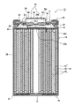
- FIG. 1 is a cross-sectional view of a sealed battery according to an embodiment;
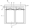
- FIG. It is a figure which shows the external appearance of the battery pack of embodiment. It is a figure explaining the internal structure of the battery pack of embodiment.
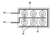
- FIG. 4 is a diagram showing the arrangement of current collector plates in the battery pack of the embodiment;
- FIG. 4 is a view showing the outer cans used in Examples and Comparative Examples, and is a view in the case where the outer cans are not provided with an explosion-proof valve.
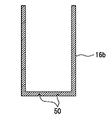
- FIG. 4 is a view showing the outer cans used in Examples and Comparative Examples, in which an explosion-proof valve is provided at the bottom of the outer can.
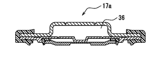
- FIG. 4 is a diagram showing the form of the sealing body of the batteries used in Examples and Comparative Examples, in the case of having an explosion-proof valve on the top surface of the sealing body.
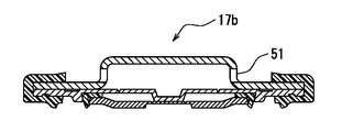
- FIG. 4 is a diagram showing the form of the sealing body of the batteries used in Examples and Comparative Examples, in the case of having a gas discharge hole on the side surface of the sealing body.
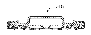
- FIG. 4 is a diagram showing the form of the sealing member of the batteries used in Examples and Comparative Examples, and is a diagram in which the sealing member has neither an explosion-proof valve nor a gas discharge hole.
- FIG. 4 is a cross-sectional view of a battery holder used in Examples and Comparative Examples, and is a view of the battery holder for discharging gas from the upper surface.
- FIG. 4 is a cross-sectional view of a battery holder used in Examples and Comparative Examples, and is a view of the battery holder for discharging gas from the bottom surface.
- a non-aqueous electrolyte secondary battery in which the electrode body 14 is housed in a bottomed cylindrical outer can 16 and which includes a sealing body 17 that closes the opening of the outer can 16 will be exemplified.
- the present invention can also be applied to various types of sealed batteries such as nickel-hydrogen secondary batteries.
- FIG. 1 is a cross-sectional view of a sealed battery 10 according to one embodiment of the present disclosure.
- the sealed battery 10 includes a bottomed cylindrical outer can 16 , a sealing member 17 that closes the opening of the outer can 16 , and a gasket 27 interposed between the outer can 16 and the sealing member 17 .
- the sealed battery 10 also includes an electrode body 14 and an electrolyte housed in an outer can 16 .
- the electrode body 14 includes a positive electrode 11, a negative electrode 12, and a separator 13, and has a structure in which the positive electrode 11 and the negative electrode 12 are spirally wound with the separator 13 interposed therebetween.
- a non-aqueous electrolyte includes a non-aqueous solvent and an electrolyte salt dissolved in the non-aqueous solvent.
- the non-aqueous solvent include esters, ethers, nitriles, amides, and mixed solvents of two or more thereof.
- the non-aqueous solvent may contain a halogen-substituted product obtained by substituting at least part of the hydrogen atoms of the solvent with halogen atoms such as fluorine.
- the non-aqueous electrolyte is not limited to a liquid electrolyte, and may be a solid electrolyte using a gel polymer or the like.
- a lithium salt such as LiPF6 is used as the electrolyte salt.
- the electrode assembly 14 has a long positive electrode 11, a long negative electrode 12, and two long separators 13. Further, the electrode body 14 has a positive electrode lead 20 joined to the positive electrode 11 and a negative electrode lead 21 joined to the negative electrode 12 .
- the negative electrode 12 is formed to be larger than the positive electrode 11 and longer than the positive electrode 11 in the longitudinal direction and the width direction (transverse direction) in order to suppress deposition of lithium.
- the two separators 13 are at least one size larger than the positive electrode 11 and are arranged so as to wrap the positive electrode 11 vertically, for example.
- the positive electrode 11 has a positive electrode current collector and positive electrode mixture layers formed on both sides of the positive electrode current collector.
- a foil of a metal such as aluminum or an aluminum alloy that is stable in the potential range of the positive electrode 11, a film having the metal on the surface layer, or the like can be used.
- the positive electrode mixture layer contains a positive electrode active material, a conductive agent, and a binder.
- a positive electrode mixture slurry containing a positive electrode active material, a conductive agent, a binder, and the like is applied onto a positive electrode current collector, the coating film is dried, and then compressed to form a positive electrode mixture layer. It can be produced by forming on both sides of the current collector.
- the positive electrode active material is composed mainly of a lithium-containing metal composite oxide.
- Metal elements contained in the lithium-containing metal composite oxide include Ni, Co, Mn, Al, B, Mg, Ti, V, Cr, Fe, Cu, Zn, Ga, Sr, Zr, Nb, In, Sn , Ta, W, and the like.
- An example of a preferable lithium-containing metal composite oxide is a composite oxide containing at least one of Ni, Co, Mn and Al.
- Carbon materials such as carbon black, acetylene black, ketjen black, and graphite can be exemplified as the conductive agent contained in the positive electrode mixture layer.
- the binder contained in the positive electrode mixture layer include fluororesins such as polytetrafluoroethylene (PTFE) and polyvinylidene fluoride (PVdF), polyacrylonitrile (PAN), polyimide, acrylic resins, and polyolefins. These resins may be used in combination with cellulose derivatives such as carboxymethyl cellulose (CMC) or salts thereof, polyethylene oxide (PEO), and the like.
- the negative electrode 12 has a negative electrode current collector and negative electrode mixture layers formed on both sides of the negative electrode current collector.
- a foil of a metal such as copper or a copper alloy that is stable in the potential range of the negative electrode 12, a film having the metal on the surface layer, or the like can be used.
- the negative electrode mixture layer contains a negative electrode active material and a binder.
- a negative electrode current collector is coated with a negative electrode mixture slurry containing a negative electrode active material, a binder, and the like. can be produced by forming on both sides of the
- a carbon material that reversibly absorbs and releases lithium ions is generally used as the negative electrode active material.
- Preferred carbon materials are graphite such as natural graphite such as flake graphite, massive graphite and earthy graphite, massive artificial graphite and artificial graphite such as graphitized mesophase carbon microbeads.
- the negative electrode mixture layer may contain a Si-containing compound as a negative electrode active material.
- a metal other than Si that forms an alloy with lithium, an alloy containing the metal, a compound containing the metal, or the like may be used as the negative electrode active material.
- the binder contained in the negative electrode mixture layer may be fluororesin, PAN, polyimide resin, acrylic resin, polyolefin resin, or the like, but preferably styrene-butadiene rubber (SBR ) or its modified form.
- the negative electrode mixture layer may contain, for example, CMC or its salt, polyacrylic acid (PAA) or its salt, polyvinyl alcohol, etc. in addition to SBR or the like.
- a porous sheet having ion permeability and insulation is used for the separator 13 .
- porous sheets include microporous thin films, woven fabrics, and non-woven fabrics.
- olefin resin such as polyethylene and polypropylene, cellulose, and the like are preferable.
- the separator 13 may have either a single layer structure or a laminated structure.
- a heat-resistant layer or the like may be formed on the surface of the separator 13 .
- the negative electrode 12 may constitute the winding start end of the electrode body 14, but in general, the separator 13 extends beyond the winding start side end of the negative electrode 12, and the winding start side end of the separator 13 is the electrode body. 14 winding start end.
- the positive electrode lead 20 is electrically connected to the intermediate portion of the positive electrode core in the winding direction
- the negative electrode lead 21 is electrically connected to the winding end portion of the negative electrode core in the winding direction.
- the negative electrode lead may be electrically connected to the winding start end of the negative electrode core in the winding direction.
- the electrode body has two negative leads, one negative lead is electrically connected to the winding start end of the negative electrode core in the winding direction, and the other negative lead is connected to the winding of the negative electrode core. It may be electrically connected to the winding end portion in the winding direction.
- the negative electrode and the outer can may be electrically connected by bringing the winding end portion of the negative electrode core in the winding direction into contact with the inner surface of the outer can.
- the sealed battery 10 further has an insulating plate 18 arranged above the electrode assembly 14 and an insulating plate 19 arranged below the electrode assembly 14 .
- the positive electrode lead 20 attached to the positive electrode 11 extends through the through hole of the insulating plate 18 toward the sealing member 17
- the negative electrode lead 21 attached to the negative electrode 12 extends outside the insulating plate 19 . and extend to the bottom 31 side of the outer can 16 .
- the positive electrode lead 20 is connected to the lower surface of the inner terminal plate 23, which is the bottom plate of the sealing member 17, by welding or the like. becomes.
- the negative electrode lead 21 is connected to the inner surface of the bottom 31 of the outer can 16 by welding or the like, and the outer can 16 becomes the negative external terminal.
- the structure of the sealing member 17 will be described later in detail.
- the outer can 16 is a metal container having a cylindrical shape with a bottom.
- a ring-shaped gasket 27 seals between the outer can 16 and the sealing body 17, and the internal space of the battery is sealed by the seal.
- the gasket 27 is sandwiched between the outer can 16 and the sealing member 17 to insulate the sealing member 17 from the outer can 16 .
- the gasket 27 serves as a sealing material for keeping the inside of the battery airtight and prevents leakage of the electrolyte.
- Gasket 27 also serves as an insulating material that prevents short circuit between outer can 16 and sealing member 17 .
- a grooved portion 22 is provided in the upper portion of the outer can 16 by spinning a part of the outer peripheral surface of the cylinder and recessed radially inward. is provided.
- the bottomed cylindrical portion 29 accommodates the electrode body 14 and the non-aqueous electrolyte, and the crimped portion 28 is bent radially inward from the opening-side end of the bottomed cylindrical portion 29 to extend radially inward. extends inwardly of the
- the sealing member 17 is clamped together with the gasket 27 between the crimped portion 28 and the upper side of the grooved portion 22 and fixed to the outer can 16 .
- the sealing member 17 has a structure in which an internal terminal plate 23, an insulating member 25, a rupture disk 24, and a cap 30 are arranged side by side.
- Each member constituting the sealing member 17 has, for example, a disk shape or a ring shape, and each member other than the insulating member 25 is electrically connected to each other.
- the internal terminal plate 23 is a disk-shaped metal plate, and the diameter of the internal terminal plate 23 is smaller than that of the rupture disk 24 .
- a central portion of the internal terminal plate 23 forms a thin portion 23a formed to be thin.
- a notch portion 23b is formed around the thin portion 23a.
- An insulating member 25 is attached to the peripheral edge of the internal terminal plate 23 .
- the rupture disk 24 is a disk-shaped metal plate, and has a protrusion 24a on its lower surface.
- the internal terminal plate 23 is fixed to the rupture disk 24 via the insulating member 25 by crimping radially inward.
- a recess 24b is provided in the central portion of the rupture disk 24, contacts the internal terminal plate 23, and is electrically connected by welding.
- the rupture disk 24 has a circumferential groove 24c.
- the rupture disk 24 and the internal terminal plate 23 form a current interrupting mechanism. As will be described later, the cut portion 23b of the internal terminal plate 23 is broken, the thin portion 23a is separated from the internal terminal plate 23, and the portion of the internal terminal plate 23 to which the positive electrode lead 20 is connected is disconnected from the rupture disk 24. It is configured such that the current path is interrupted by cutting.
- the cap 30 has a circular protuberant top surface portion 33 in the center in the radial direction, and a flange portion 32 extending around the top surface portion 33 toward the peripheral edge portion.
- the cap 30 is electrically connected to the rupture disk 24 at its peripheral edge, and the cap 30 constitutes the positive electrode of the battery.
- An explosion-proof valve 35 is formed on the top surface portion 33 of the cap 30 .
- the explosion-proof valve 35 is formed by a groove or the like formed by engraving or the like on the top surface portion 33 of the cap 30 .
- the shape of the explosion-proof valve 35 may be C-shaped, round, or any other shape. Note that the explosion-proof valve 35 may not be provided on the top surface portion 33 of the cap 30 . It may be provided at a radial corner of the top surface portion 33 of the cap 30 or at a side surface portion 34 connecting the top surface portion 33 to the flange portion 32 .
- the sealed battery 10 of this embodiment does not have a gas discharge hole in the cap 30 . Therefore, the sealing member 17 of the sealed battery 10 of this embodiment forms a sealed space 36 between the rupture disk 24 and the cap 30 . Since the sealed battery 10 is sealed from the outside of the battery, it becomes difficult to transfer air flow and temperature outside the battery to the inside of the battery. As will be described later, the sealed space 36 seals the rupture disk 24 from the outside of the battery, so that even if an adjacent battery in an adjacently arranged battery pack discharges gas, it will not be affected easily. ing.
- the thin portion 23a of the internal terminal plate 23 When the gas pressure inside the battery increases due to an internal short circuit or the like, the thin portion 23a of the internal terminal plate 23 generates pressure that pushes the rupture disk 24 toward the cap 30 side.
- the gas pressure inside the battery exceeds a predetermined pressure with respect to the pressure inside the closed space 36, the thin portion 23a of the internal terminal plate 23 is broken at the notch portion 23b, and the rupture disk 24 and the thin portion 23a are connected to the internal terminal. away from the plate 23; As a result, the current path between the rupture disk 24 and the internal terminal plate 23 is cut off.
- the groove 24c of the rupture disk 24 breaks, breaking the sealing of the sealed space 36, and the pressure in the sealed space 36 rises due to the generated gas pressure in the battery.
- the explosion-proof valve 35 provided in the cap 30 breaks and the gas is discharged to the outside of the battery. This prevents the battery from exploding due to an increase in internal pressure.
- the current interrupting mechanism of this embodiment cuts the connection between the rupture disk 24 and the internal terminal plate 23
- the explosion-proof mechanism consists of the groove 24 c of the rupture disk 24 and the explosion-proof valve 35 of the cap 30 . It consists of two stages. However, the explosion-proof mechanism does not necessarily have to be two stages. For example, if the rupture disk 24 is provided with a through-hole instead of the groove 24c, the explosion-proof valve 35 of the cap 30 alone can be used as the explosion-proof mechanism.
- the operating pressure of the current interrupting mechanism is set lower than the operating pressure of the explosion-proof mechanism.
- early interruption of the current path can prevent excessive current from flowing from adjacent batteries.
- the gas pressure will rise further. Form a path to prevent rupture due to increased gas pressure inside the battery. Therefore, it is preferable to set the operating pressure of the current interrupting mechanism lower than the operating pressure of the explosion-proof mechanism.
- the operating pressure of the current interrupting mechanism and the explosion-proof mechanism can be set by adjusting the plate thickness of the thin portion 23 a of the internal terminal plate 23 and the plate thickness of the explosion-proof valve 35 .
- the plate thickness of the thin portion 23 a of the internal terminal plate 23 can be thinner than the plate thickness of the explosion-proof valve 35 .
- the depth of engraving can be adjusted.
- it can be adjusted by the material of which the inner terminal plate 23 and the cap 30 are made.
- FIG. 2 is a diagram showing the appearance of a battery pack 40 containing a plurality of sealed batteries 10 of this embodiment.
- the battery pack 40 has a resin-made exterior case 41 that accommodates a plurality of sealed batteries 10, and a positive terminal 42 and a negative terminal 43 that are connection terminals to the outside.
- a positive terminal 42 and a negative terminal 43 of the battery pack 40 are pulled out from the upper end of one side surface of the exterior case 41 .
- the exterior case 41 has a gas discharge path 44 inside the upper surface of the other side corresponding to one side from which the positive electrode terminal 42 and the negative electrode terminal 43 are drawn out, and a gas discharge valve 45 at the upper end of the other side. have.
- the battery pack 40 of this embodiment has a box shape, it can be changed by the number and arrangement of the sealed batteries 10 housed therein.
- FIG. 3 is a diagram showing the outline of the internal structure of the battery pack 40 of this embodiment.
- the battery pack 40 houses a plurality of sealed batteries 10 .
- the plurality of sealed batteries 10 are housed with all positive terminals (caps 30) aligned in one direction. This makes it possible to collectively wire the positive terminal and the negative terminal, which contributes to increasing the volumetric energy density of the battery pack 40 .
- the positive terminals of the plurality of sealed batteries 10 are connected to the positive collector plate 47 , and the negative terminals are connected to the negative collector plate 48 .
- the positive collector plate 47 and the negative collector plate 48 are connected to the positive terminal 42 and the negative terminal 43, respectively.
- the positive terminal 42 and the negative terminal 43 are terminals for external connection, and are connected to electrical connection terminals of equipment using the battery pack.
- a gas discharge path 44 is provided on the upper surfaces of the positive terminals of the plurality of sealed batteries 10 .
- the explosion-proof valve 35 is provided on the side of the cap 30, which is the positive electrode. Therefore, it can be easily discharged to the outside of the battery pack 40 . Furthermore, by using the upper surface on which the positive electrode current collector plate 47 and the negative electrode current collector plate 48 are arranged as the gas discharge path 44, the volume of the battery pack 40 can be reduced, and the volumetric energy density can be increased.
- the gas exhaust valve 45 of the gas exhaust path 44 is normally closed so that water droplets and the like do not enter.
- the gas discharge valve 45 opens, and the gas is discharged to the outside of the battery pack 40 .
- the gas discharge valve 45 may be configured by providing a hole above the side surface of the exterior case 41 and sealing the hole.
- FIG. 4 shows an example of the arrangement of the positive collector plate 47 and the negative collector plate 48 .
- the positive terminals of the sealed battery 10 are aligned in one direction, and a wiring is connected from the positive collector plate 47 to the cap 30 (positive terminal).
- a wire is connected from the negative electrode collector plate 48 to the shoulder portion (negative electrode terminal) of the outer can 16 of the sealed battery 10 .
- the connection of the wiring is performed by welding or the like, but it is possible by various methods.
- the electrical connection between the internal terminal plate 23 and the rupture disk 24 is cut, and then the groove 24c of the rupture disk 24 is broken. is broken.
- High-temperature gas is discharged from the sealed battery 10 , and the gas fills the inside of the battery pack 40 and the gas discharge path 44 .
- the cap was provided with a gas discharge hole. Therefore, when the gas is discharged into the battery pack 40, the high temperature gas flows in from the gas discharge hole, and the high temperature gas touches the rupture disk 24 of the normal battery, exerting a thermal effect.
- the operating pressure of the rupture disk 24 was also affected by the increase in pressure inside the battery pack 40 .
- the rupture disk 24 is activated by the difference between the pressure inside the sealed battery 10 on the side of the electrode assembly 14 and the pressure outside the rupture disk 24 . Therefore, when the pressure outside the battery increases, the rupture disk 24 becomes difficult to operate.
- the cap 30 is provided with the explosion-proof valve 35 to have a sealed structure. no influx. Therefore, the rupture disk 24 is less likely to be affected by the exhaust gas.
- Example 1 [Preparation of positive electrode] Nickel cobalt lithium aluminum oxide as a positive electrode active material, acetylene black as a conductive aid, and polyvinylidene fluoride as a binder were used and mixed with an N-methylpyrrolidone (NMP) solution to obtain a positive electrode mixture slurry. . This positive electrode mixture slurry was applied to both sides of an aluminum positive electrode current collector, dried and rolled to obtain a positive electrode.
- NMP N-methylpyrrolidone
- Graphite and a silicon-based compound were used as negative electrode active materials, carboxymethyl cellulose (CMC) as a thickener, and styrene-butadiene rubber (SBR) as a binder, and mixed with water to obtain a negative electrode mixture slurry.
- This negative electrode mixture slurry was applied to both surfaces of a negative electrode current collector made of copper, dried and rolled to obtain a negative electrode.
- Electrode body was obtained by winding the above positive electrode and negative electrode with a separator made of a polyethylene microporous film interposed therebetween.
- a non-aqueous solvent was obtained by mixing ethylene carbonate (EC), ethyl methyl carbonate (EMC), and dimethyl carbonate (DMC).
- a non-aqueous electrolyte was obtained by dissolving lithium hexafluorophosphate (LiPF6) as an electrolyte salt in this non-aqueous solvent.
- the electrode body is inserted into a cylindrical outer can 16a shown in FIG. 5A, a non-aqueous electrolyte is injected, and a sealing body 17a shown in FIG. 6A is crimped to the open end of the outer can 16a to complete a sealed battery. let me The sealing body 17a has an explosion-proof valve on the top surface of the sealing body and forms a sealed space with the rupture disk.
- Example 1 A battery pack was fabricated in the same manner as in Example 1, except that the sealing member 17b provided with gas exhaust holes 51 on the top surface shown in FIG. 6B was used instead of the sealing member 17a of the battery pack of Example 1. .
- a sealing body 17c having neither an explosion-proof valve nor a gas discharge hole on the top surface shown in FIG. 6C was used.
- an outer can 16b having an explosion-proof mechanism 50 on the bottom portion shown in FIG. 5B is used, and instead of the battery holder 46a, a gas discharge hole 52 is provided at the bottom of the battery insertion portion 49 as shown in FIG. 7B.
- the gas discharge path was installed on the bottom surface of the sealed battery.
- a battery pack was produced in the same manner as in Example 1 except for the above.
- Example 2 A battery pack was produced in the same manner as in Example 1, except that the battery pack of Example 1 was sealed with a polyvinyl chloride (PVC) film.
- PVC polyvinyl chloride
- Comparative Example 3 A battery pack was produced in the same manner as in Example 1, except that the battery pack of Comparative Example 1 was sealed with a polyvinyl chloride (PVC) film.
- PVC polyvinyl chloride
- the reliability index during battery thermal runaway was evaluated by the following procedure. First, the battery pack was continuously charged at a current value of 1 hour rate in an atmosphere of 25° C., and the time T1 at which the current interrupting mechanism was activated and the current stopped flowing was measured. Next, another battery pack was continuously charged at a current value of 1 hour rate in an atmosphere of 25°C, and at the point of time (T1-3 seconds), the sealed battery was forcibly closed by sticking a nail into the side of the battery pack. Thermal runaway was caused, and the time T2 during which the current interrupting mechanism of the adjacent sealed battery was activated and the current stopped flowing was measured and used as a reliability index.
- Table 1 shows the volumetric energy density (Wh/L) of the battery pack, the operating pressure (MPa) of the current interrupting mechanism of the adjacent battery after battery thermal runaway, and the reliability index during battery thermal runaway for each of the battery packs. T2 is shown. The volumetric energy density of the battery pack and the operating pressure evaluation result of the current interrupting mechanism of the adjacent battery after battery thermal runaway were indexed with the numerical value of Example 1 being 100.
- the batteries of Examples 1 and 2 have an adjacent battery current cut-off time T2 of 3 seconds, and no delay occurs.
- the current interrupting mechanism of the batteries of Examples 1 and 2 is structured to operate by the pressure difference between the pressure in the closed space between the cap inside the battery and the current interrupting mechanism and the pressure in the battery power generation section. This is thought to be due to the fact that the pressure rise in the battery pack due to the discharge of high-temperature gas from the battery is less likely to affect it.
- the battery packs of Examples 1 and 2 which did not have a gas discharge hole on the top surface of the sealing member, maintained a higher volumetric energy density than the battery packs of Comparative Examples 1 to 3, and at the time of battery thermal runaway. It can be seen that reliability is ensured.
Landscapes
- Chemical & Material Sciences (AREA)
- Chemical Kinetics & Catalysis (AREA)
- Electrochemistry (AREA)
- General Chemical & Material Sciences (AREA)
- Gas Exhaust Devices For Batteries (AREA)
Abstract
Description
また、電池パックを高エネルギー密度化する技術として、円筒形電池を直並列に複数接続する為の正極集電板および負極集電板を、同一平面上に配置して集電板の占める容積をコンパクトにして、高エネルギー密度化する技術がある。
特許文献1には、電流遮断機構と防爆機構を封口体内部の弁体によって構成した密閉型電池が記載されている。
[正極の作製]
正極活物質としてニッケルコバルトアルミニウム酸リチウムを、導電助剤としてのアセチレンブラックを、結着剤としてのポリフッ化ビニリデンを用い、N-メチルピロリドン(NMP)溶液と混合して正極合剤スラリーを得た。この正極合剤スラリーを、アルミニウム製の正極集電体の両面に塗布し、乾燥・圧延して正極を得た。
負極活物質として黒鉛、珪素系化合物を、増粘剤としてカルボキシメチルセルロース(CMC)を、結着剤としてスチレン-ブタジエンゴム(SBR)を用い、水と混合して負極合剤スラリーを得た。この負極合剤スラリーを、銅製の負極集電体の両面に塗布し、乾燥・圧延して負極を得た。
上記正極および負極を、ポリエチレン製微多孔膜からなるセパレータを介して捲回することにより、電極体を得た。
エチレンカーボネート(EC)と、エチルメチルカーボネート(EMC)と、ジメチルカーボネート(DMC)を混合して非水溶媒を得た。この非水溶媒に電解質塩としてのヘキサフルオロリン酸リチウム(LiPF6)を溶解して非水電解質を得た。
電極体を円筒形の図5Aに示す外装缶16aに挿入し、非水電解質を注液し、外装缶16aの開口端に、図6Aに示す封口体17aをかしめることにより密閉型電池を完成させた。封口体17aは、封口体天面に防爆弁を有し、ラプチャーディスクとの間に密閉空間を形成している。
上述の方法で作製した密閉型電池6本を図7Aに示す直方体形の電池ホルダー46aの電池挿入部49に挿入し、正極集電板および負極集電板を設置し、密閉型電池と集電板を溶接し、外装ケースに挿入することにより電池パックを作製した。
実施例1の電池パックの封口体17aに変えて、図6Bに示す天面部にガス排気孔51を設けた封口体17bを用いたこと以外は、実施例1と同様にして電池パックを作製した。
実施例1の電池パックの封口体17aに変えて、図6Cに示す天面部に防爆弁もガス排出孔も有しない封口体17cを用いた。外装缶16aに変えて、図5Bに示す底面部に防爆機構50を有する外装缶16bを用い、電池ホルダー46aに変えて、図7Bに示すように電池挿入部49の底にガス排出孔52を有する電池ホルダー46bを用いて、ガス排出経路を密閉型電池の底面部に設置した。上記以外は、実施例1と同様にして電池パックを作製した。
実施例1の電池パックをポリ塩化ビニル(PVC)フィルムで密封したこと以外は、実施例1と同様にして電池パックを作製した。
比較例1の電池パックをポリ塩化ビニル(PVC)フィルムで密封したこと以外は、実施例1と同様にして電池パックを作製した。
実施例1,2および比較例1~3の電池パックの外径寸法から、それぞれの電池パックの体積エネルギー密度(Wh/L)を算出した。
電池熱暴走時の隣接電池への影響を、次の手順により評価した。25℃雰囲気下において電池パックを満充電し、電池パックの側面から釘を刺すことで密閉型電池を強制的に熱暴走させた。電池パックが25℃まで十分に冷却された後に解体して、強制的に熱暴走させた密閉型電池と隣接する密閉型電池を取り出した。隣接する密閉型電池を解体して封口体を取り出し、電流遮断機構の作動圧(MPa)を測定した。
表1に電池パックのそれぞれについて、電池パックの体積エネルギー密度(Wh/L)、電池熱暴走後の隣接電池の電流遮断機構の作動圧(MPa)、および電池熱暴走時の信頼性指標としたT2を示す。電池パックの体積エネルギー密度、および電池熱暴走後の隣接電池の電流遮断機構の作動圧評価結果は、実施例1の数値を100として指標化した。

Claims (5)
- 電極体を収容する有底筒状の外装缶と、
前記外装缶の開口部を塞ぐ封口体と、
を備え、
前記封口体は、前記外装缶とともに、前記電極体を密閉し、電池内部のガス圧に感応して作動する電流遮断機構と、前記電流遮断機構の上に密閉空間を形成するキャップと、を有し、
前記キャップは、前記密閉空間内部のガス圧に感応して開く防爆弁を有する、
密閉型電池。 - 前記電流遮断機構が作動した後に、前記防爆弁が作動するように、前記電流遮断機構および前記防爆弁の感応特性を調整した、
請求項1に記載の密閉型電池。 - 請求項1または2に記載の密閉型電池を複数有した電池パックであって、
前記電池パック内において、前記複数の密閉型電池の正極端子を一方向に揃えて配置した、
電池パック。 - 前記複数の密閉型電池の前記正極端子が配置された前記電池パックの内部に、閉じられたガス排出経路を更に有する、
請求項3に記載の電池パック。 - 前記ガス排出経路は、前記密閉型電池からガスが放出され、前記電池パック内の圧力が上昇した場合に開く、ガス排出弁を有する、
請求項4に記載の電池パック。
Priority Applications (3)
| Application Number | Priority Date | Filing Date | Title |
|---|---|---|---|
| US18/281,368 US20240162584A1 (en) | 2021-03-19 | 2022-03-08 | Sealed battery, and battery pack using same |
| CN202280019854.7A CN117083764A (zh) | 2021-03-19 | 2022-03-08 | 密闭型电池及使用了该密闭型电池的电池组 |
| JP2023507002A JPWO2022196451A1 (ja) | 2021-03-19 | 2022-03-08 |
Applications Claiming Priority (2)
| Application Number | Priority Date | Filing Date | Title |
|---|---|---|---|
| JP2021-045837 | 2021-03-19 | ||
| JP2021045837 | 2021-03-19 |
Publications (1)
| Publication Number | Publication Date |
|---|---|
| WO2022196451A1 true WO2022196451A1 (ja) | 2022-09-22 |
Family
ID=83320437
Family Applications (1)
| Application Number | Title | Priority Date | Filing Date |
|---|---|---|---|
| PCT/JP2022/010062 Ceased WO2022196451A1 (ja) | 2021-03-19 | 2022-03-08 | 密閉型電池、およびこれを使用した電池パック |
Country Status (4)
| Country | Link |
|---|---|
| US (1) | US20240162584A1 (ja) |
| JP (1) | JPWO2022196451A1 (ja) |
| CN (1) | CN117083764A (ja) |
| WO (1) | WO2022196451A1 (ja) |
Citations (4)
| Publication number | Priority date | Publication date | Assignee | Title |
|---|---|---|---|---|
| JP2011070871A (ja) * | 2009-09-25 | 2011-04-07 | Panasonic Corp | 電池モジュールとそれを用いた電池パック |
| WO2015146078A1 (ja) * | 2014-03-28 | 2015-10-01 | 三洋電機株式会社 | 円筒形密閉電池及び電池パック |
| WO2019163440A1 (ja) * | 2018-02-26 | 2019-08-29 | 三洋電機株式会社 | 非水電解質二次電池 |
| WO2020129479A1 (ja) * | 2018-12-17 | 2020-06-25 | 三洋電機株式会社 | 密閉電池 |
Family Cites Families (4)
| Publication number | Priority date | Publication date | Assignee | Title |
|---|---|---|---|---|
| US8241772B2 (en) * | 2009-06-12 | 2012-08-14 | Tesla Motors, Inc. | Integrated battery pressure relief and terminal isolation system |
| KR102142087B1 (ko) * | 2016-10-11 | 2020-08-06 | 주식회사 엘지화학 | 배터리 팩 |
| CN111033807B (zh) * | 2017-08-31 | 2023-07-11 | 松下知识产权经营株式会社 | 电池块以及具备该电池块的电池模块 |
| CN110071245B (zh) * | 2019-04-29 | 2023-12-12 | 苏州安靠电源有限公司 | 电池模组和电池包 |
-
2022
- 2022-03-08 WO PCT/JP2022/010062 patent/WO2022196451A1/ja not_active Ceased
- 2022-03-08 US US18/281,368 patent/US20240162584A1/en active Pending
- 2022-03-08 JP JP2023507002A patent/JPWO2022196451A1/ja active Pending
- 2022-03-08 CN CN202280019854.7A patent/CN117083764A/zh active Pending
Patent Citations (4)
| Publication number | Priority date | Publication date | Assignee | Title |
|---|---|---|---|---|
| JP2011070871A (ja) * | 2009-09-25 | 2011-04-07 | Panasonic Corp | 電池モジュールとそれを用いた電池パック |
| WO2015146078A1 (ja) * | 2014-03-28 | 2015-10-01 | 三洋電機株式会社 | 円筒形密閉電池及び電池パック |
| WO2019163440A1 (ja) * | 2018-02-26 | 2019-08-29 | 三洋電機株式会社 | 非水電解質二次電池 |
| WO2020129479A1 (ja) * | 2018-12-17 | 2020-06-25 | 三洋電機株式会社 | 密閉電池 |
Also Published As
| Publication number | Publication date |
|---|---|
| JPWO2022196451A1 (ja) | 2022-09-22 |
| CN117083764A (zh) | 2023-11-17 |
| US20240162584A1 (en) | 2024-05-16 |
Similar Documents
| Publication | Publication Date | Title |
|---|---|---|
| JP6490053B2 (ja) | 円筒形密閉電池及び電池パック | |
| JP6538650B2 (ja) | 円筒形密閉電池 | |
| US10224533B2 (en) | Secondary battery comprising current interrupt device | |
| CN107431178B (zh) | 圆筒形电池 | |
| JP7709293B2 (ja) | 円筒形電池 | |
| WO2021106729A1 (ja) | 密閉電池 | |
| WO2013046712A1 (ja) | 密閉型二次電池 | |
| WO2020004135A1 (ja) | 非水電解質二次電池 | |
| JP2020149881A (ja) | 二次電池 | |
| US20240178522A1 (en) | Cylindrical battery | |
| US20240088390A1 (en) | Non-aqueous electrolyte secondary battery | |
| US20250183375A1 (en) | Cylindrical nonaqueous electrolyte secondary battery | |
| JP7336680B2 (ja) | 二次電池 | |
| JP2019153388A (ja) | 非水電解質二次電池 | |
| US20240313305A1 (en) | Cylindrical battery | |
| US20240154280A1 (en) | Cylindrical non-aqueous electrolyte secondary battery | |
| WO2022196451A1 (ja) | 密閉型電池、およびこれを使用した電池パック | |
| CN118575296A (zh) | 非水电解质二次电池 | |
| US20260031484A1 (en) | Nonaqueous electrolyte secondary battery | |
| WO2025225388A1 (ja) | 非水電解質二次電池 | |
| WO2026048533A1 (ja) | 円筒形二次電池 | |
| WO2025225437A1 (ja) | 非水電解質二次電池 | |
| JP2020129432A (ja) | 二次電池 | |
| JP2023077815A (ja) | 電池 | |
| WO2025143013A1 (ja) | 円筒形電池 |
Legal Events
| Date | Code | Title | Description |
|---|---|---|---|
| 121 | Ep: the epo has been informed by wipo that ep was designated in this application |
Ref document number: 22771203 Country of ref document: EP Kind code of ref document: A1 |
|
| WWE | Wipo information: entry into national phase |
Ref document number: 2023507002 Country of ref document: JP |
|
| WWE | Wipo information: entry into national phase |
Ref document number: 202280019854.7 Country of ref document: CN |
|
| WWE | Wipo information: entry into national phase |
Ref document number: 202347060875 Country of ref document: IN Ref document number: 18281368 Country of ref document: US |
|
| NENP | Non-entry into the national phase |
Ref country code: DE |
|
| 122 | Ep: pct application non-entry in european phase |
Ref document number: 22771203 Country of ref document: EP Kind code of ref document: A1 |