WO2022196426A1 - Projection system and control method for projection system - Google Patents
Projection system and control method for projection system Download PDFInfo
- Publication number
- WO2022196426A1 WO2022196426A1 PCT/JP2022/009905 JP2022009905W WO2022196426A1 WO 2022196426 A1 WO2022196426 A1 WO 2022196426A1 JP 2022009905 W JP2022009905 W JP 2022009905W WO 2022196426 A1 WO2022196426 A1 WO 2022196426A1
- Authority
- WO
- WIPO (PCT)
- Prior art keywords
- projector
- projection
- projection image
- command
- image data
- Prior art date
Links
- 238000000034 method Methods 0.000 title claims description 9
- 238000012986 modification Methods 0.000 description 55
- 230000004048 modification Effects 0.000 description 55
- 238000010586 diagram Methods 0.000 description 39
- 230000005540 biological transmission Effects 0.000 description 31
- 238000003860 storage Methods 0.000 description 27
- 238000012937 correction Methods 0.000 description 24
- 238000012545 processing Methods 0.000 description 23
- 230000006870 function Effects 0.000 description 11
- 238000005520 cutting process Methods 0.000 description 5
- 230000000694 effects Effects 0.000 description 5
- 238000005516 engineering process Methods 0.000 description 5
- 238000013507 mapping Methods 0.000 description 5
- 238000004891 communication Methods 0.000 description 4
- 238000007792 addition Methods 0.000 description 2
- 240000004282 Grewia occidentalis Species 0.000 description 1
- 206010024796 Logorrhoea Diseases 0.000 description 1
- 230000003213 activating effect Effects 0.000 description 1
- 239000000470 constituent Substances 0.000 description 1
- 238000005304 joining Methods 0.000 description 1
- 238000004519 manufacturing process Methods 0.000 description 1
- 238000002156 mixing Methods 0.000 description 1
- 230000003287 optical effect Effects 0.000 description 1
- 239000004065 semiconductor Substances 0.000 description 1
- 239000000779 smoke Substances 0.000 description 1
- 230000005236 sound signal Effects 0.000 description 1
- 230000001360 synchronised effect Effects 0.000 description 1
Images


Classifications
-
- H—ELECTRICITY
- H04—ELECTRIC COMMUNICATION TECHNIQUE
- H04N—PICTORIAL COMMUNICATION, e.g. TELEVISION
- H04N9/00—Details of colour television systems
- H04N9/12—Picture reproducers
- H04N9/31—Projection devices for colour picture display, e.g. using electronic spatial light modulators [ESLM]
- H04N9/3141—Constructional details thereof
- H04N9/3147—Multi-projection systems
-
- H—ELECTRICITY
- H04—ELECTRIC COMMUNICATION TECHNIQUE
- H04N—PICTORIAL COMMUNICATION, e.g. TELEVISION
- H04N9/00—Details of colour television systems
- H04N9/12—Picture reproducers
- H04N9/31—Projection devices for colour picture display, e.g. using electronic spatial light modulators [ESLM]
- H04N9/3179—Video signal processing therefor
- H04N9/3185—Geometric adjustment, e.g. keystone or convergence
Definitions
- the present disclosure relates to a projection system and a method of controlling the projection system.
- a so-called multi-projection system in which a plurality of projection images projected from a plurality of projectors are connected to each other and projected onto a projection surface as a single large overall projection image (see, for example, Patent Document 1).
- the present disclosure provides a projection system and a control method for the projection system that can easily control the driving of each projector.
- a projection system projects a first projection image and a second projection image onto a projection plane such that edges of the first projection image and edges of the second projection image overlap.
- a system comprising: a first projector that projects the first projection image onto the projection plane; and a second projector that projects the second projection image onto the projection plane,
- the projector comprises: first projection image data representing the first projection image cut out from the original projection image; Acquiring a first control signal, the second projector generates second projection image data representing the second projection image extracted from the original projection image, and associates the second projection image data with the second projection image data. and obtain a second control signal for controlling the driving of the second projector.
- FIG. 1 is a diagram showing an overview of a projection system according to an embodiment
- FIG. FIG. 4 is a diagram showing an example of a first projection image, a second projection image, and an overall projection image projected by the projection system according to the embodiment
- 3 is a block diagram showing the functional configuration of a media server according to the embodiment
- FIG. FIG. 4 is a diagram showing an example of a first scenario file according to the embodiment
- FIG. FIG. 10 is a diagram showing an example of a second scenario file according to the embodiment
- FIG. FIG. 10 is a diagram showing an application example of the projection system according to the embodiment
- 4 is a sequence diagram showing the flow of operations of the projection system according to the embodiment
- FIG. FIG. 10 is a diagram showing an overview of a projection system according to Modification 1;
- FIG. 11 is a block diagram showing a functional configuration of a first projector (second projector) according to modification 3;
- FIG. 12 is a diagram showing an example of a first scenario file according to modification 3;
- FIG. 12 is a diagram showing an example of a second scenario file according to modification 3; 14 is a sequence diagram showing the flow of operations of the projection system according to Modification 3.
- FIG. FIG. 12 is a block diagram showing a functional configuration of a first projector (second projector) according to modification 4;
- FIG. 11 is a sequence diagram showing the flow of operations of a projection system according to Modification 4;
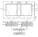
- FIG. 1 is a diagram showing an overview of a projection system 2 according to an embodiment.
- FIG. 2 is a diagram showing an example of the first projection image 12, the second projection image 14, and the overall projection image 16 projected by the projection system 2 according to the embodiment.
- the projection system 2 includes a first projector 4, a second projector 6, and an external controller 8.
- a media server 10 and a media server 11 are built in the first projector 4 and the second projector 6, respectively.
- the projection system 2 stitches together the first projection image 12 and the second projection image 14 projected from the first projector 4 and the second projector 6, respectively, to form one large overall projection image 16 on the projection plane.
- 18 is a multi-projection system.
- the “projection image” may be projection content that is either a still image or a moving image, or may be projection content that includes both a still image and a moving image.
- the first projector 4 is a projector for projecting the first projection image 12 onto the projection surface 18, and projects the first projection image 12 based on the projection content held by the media server 10.
- the second projector 6 is a projector for projecting the second projection image 14 onto the projection surface 18, and projects the second projection image 14 based on the projection content held by the media server 11.
- the external controller 8 is, for example, a personal computer, and is communicably connected to the media servers 10 and 11 via a LAN (Local Area Network) cable using Internet protocols such as TCP/IP. Specifically, the external controller 8 is connected to the media server 10 and media server 11 via the network switch 13 .
- the connections between the external controller 8 and the media servers 10 and 11 are not limited to wired connections, and may be connections through various types of wireless communication. Examples of various wireless communications include WiFi (registered trademark), WiMax (registered trademark), WLAN (Wireless Local Area Network), WiFi-Direct, LiFi (Light Fidelity), ZigBee (registered trademark), Bluetooth (registered trademark), etc. Radio frequency (RF) may be used, or optical communication such as infrared communication may be used.
- RF Radio frequency
- the first projection image 12 and the second projection image 14 are divided into the right end portion of the first projection image 12 and the left end portion of the second projection image 14. so-called edge blending is performed to project onto the projection plane 18 in such a manner that the .
- FIG. 2 is a diagram showing a state in which only the first projector 4 is driven.
- the first projection image 12 projected by the first projector 4 is an image obtained by cutting out the left portion of the original projection image 20 from the original projection image 20 .
- the brightness of the right edge of the first projection image 12, that is, the superimposed region 12a overlapping the second projection image 14, is lower than the brightness of the other region 12b.
- FIG. 2 is a diagram showing a state in which only the second projector 6 is driven.
- the second projection image 14 projected by the second projector 6 is an image obtained by cutting out the right portion of the original projection image 20 from the original projection image 20 .
- the brightness of the left edge of the second projection image 14, that is, the superimposed region 14a that overlaps the first projection image 12, is lower than the brightness of the other region 14b.
- FIG. 2 is a diagram showing a state in which both the first projector 4 and the second projector 6 are driven.
- the superimposed region 12a of the first projected image 12 and the superimposed region 14a of the second projected image 14 are superimposed on each other, so that the entire projected image 16 is projected onto the projection plane 18. be.
- the overall projection image 16 is the same image as the original projection image 20 before the first projection image 12 (or the second projection image 14) is cut out. Further, the brightness of the region where the superimposed region 12a of the first projected image 12 and the superimposed region 14a of the second projected image 14 overlap in the entire projected image 16 is approximately equal to the brightness of the other regions.
- the external controller 8 generates a first scenario file (an example of first command data) and a second scenario file (an example of second command data), and the generated first scenario file and the second scenario
- the files are sent to media server 10 and media server 11, respectively.
- the media server 10 of the first projector 4 controls driving of the first projector 4 based on the first scenario file from the external controller 8. Also, the media server 11 of the second projector 6 controls driving of the second projector 6 based on the second scenario file from the external controller 8 .
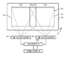
- FIG. 3 is a block diagram showing the functional configuration of the media server 10 (11) according to the embodiment.
- FIG. 4 is a diagram showing an example of a first scenario file according to the embodiment.
- FIG. 5 is a diagram showing an example of a second scenario file according to the embodiment.
- FIG. 6 is a diagram showing an application example of the projection system 2 according to the embodiment.
- the media server 10 has a reception section 22 (an example of a first reception section), a storage section 24, a generation section 26, and a transmission section 28 as functional configurations.
- the media server 11 has, as a functional configuration, a receiving unit 22 (an example of a second receiving unit), a storage unit 24, a generating unit 26, and a transmitting unit 28, similarly to the media server 10.
- the receiving unit 22 of the media server 10 receives the first scenario file from the external controller 8 and stores the received first scenario file in the storage unit 24 of the media server 10.
- the receiving unit 22 of the media server 11 receives the second scenario file from the external controller 8 and causes the storage unit 24 of the media server 11 to store the received second scenario file.
- FIG. 6 A case of applying the projection system 2 to, for example, projection mapping on a theater stage 30 as shown in FIG. 6 will be described below.
- the play of the second scene is performed.
- a play is performed with props 32 set on the stage 30 .
- a first projected image 12A and a second projected image 14A are projected from the first projector 4 and the second projector 6, respectively, using the front surface (spectator side surface) of the prop 32 as a projection surface.
- an overall projected image 16A for the first scene is projected in front of the prop 32.
- FIG. 6(a) for convenience of explanation, the letter "A" representing the overall projection image 16A is shown in front of the prop 32.
- a play is performed with the props 32 removed from the stage 30 .
- a first projected image 12B and a second projected image 14B are projected from the first projector 4 and the second projector 6, respectively, with the front (spectator side) of the stage background 34 installed behind the stage 30 as the projection surface. is projected.
- the overall projection image 16B for the second scene is projected in front of the stage background 34 .
- the character "B" representing the overall projection image 16B is shown in front of the stage background 34.
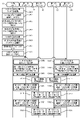
- FIG. 4 shows the structure of the first scenario file received by the media server 10 of the first projector 4 from the external controller 8.
- the first scenario file includes original projection image data (first scene), a first image clipping command, a first superimposed area generation command, and a first image geometric correction command. and a first control command.
- first image clipping command, the first superimposed area generation command, and the first image geometric correction command may be collectively referred to as "first image processing command".
- the original projection image data (first scene) is image data representing the original projection image that is the basis of the overall projection image 16A for the first scene.
- the first image clipping command is to clip the first projection image 12A for the first scene from the original projection image indicated by the original projection image data (first scene) to generate the first projection image data.
- the first image clipping command is associated with the original projection image data (first scene). Note that the first image clipping command includes position coordinates in the original projection image 20 .
- the first superimposed area generation command instructs the media server 10 to set the superimposed area 12Aa of the first projection image 12A and to make the brightness of the superimposed area 12Aa lower than the brightness of the other area 12Ab.
- This command is for The first superimposed area generation command is associated with the original projection image data (first scene).
- the first image geometric correction command is a command for instructing the media server 10 to perform geometric correction for projecting the first projected image 12A onto the front surface of the prop 32 without distortion.
- the first image geometric correction command is associated with original projection image data (first scene).
- various geometric distortion corrections can be applied as the geometric correction. For example, four-corner correction for each vertex of a rectangular projection image, or point correction using each point as a starting point by setting a plurality of points in a grid of N ⁇ M (N and M are integers) in the projection image. There may be.
- the first control command is a command for instructing the media server 10 to generate the first control signal.
- the first control signal is a signal for controlling the driving of the first projector 4.
- the first projection image 12A is focused on a predetermined area in front of the prop 32. It is a signal for controlling projection functions (each function of the projection unit 44 and the function unit 46 described later) such as focus, zoom and brightness of the light source of the first projector 4 in order to project.
- the first control command is associated with the original projection image data (first scene).
- the first scenario file includes original projection image data (second scene), a first image clipping command, a first superimposed area generation command, and a first image geometry It includes a correction command and a first control command.
- the original projection image data (second scene) is image data representing the original projection image that is the basis of the overall projection image 16B for the second scene. Note that the second scene may be a scene after the first scene in chronological order.
- the first image clipping command is to clip the first projection image 12B for the second scene from the original projection image indicated by the original projection image data (second scene) to generate the first projection image data.
- the first image clipping command is associated with the original projection image data (second scene). Note that the first image clipping command includes position coordinates in the original projection image 20 .
- the first superimposed area generation command instructs the media server 10 to set the superimposed area 12Ba of the first projection image 12B and to make the brightness of the superimposed area 12Ba lower than the brightness of the other area 12Bb.
- This command is for The first superimposed area generation command is associated with the original projection image data (second scene).
- the first image geometric correction command is a command for instructing the media server 10 to perform geometric correction for projecting the first projected image 12B onto the front of the stage background 34 without distortion.
- the first image geometric correction command is associated with the original projection image data (second scene).
- the first control command is a command for instructing the media server 10 to generate the first control signal.
- the first control signal is a signal for controlling the driving of the first projector 4.
- the first projection image 12B is focused on a predetermined area in front of the stage background 34. It is a signal that controls projection functions such as focus, zoom and brightness of the light source of the first projector 4 in order to project.
- the first control command is associated with the original projection image data (second scene).
- first image clipping command associated with the original projection image data (first scene) and the first image clipping command associated with the original projection image data (second scene) are the same. , or commands with different contents.
- first control command associated with the original projection image data (first scene) and the first control command associated with the original projection image data (second scene) have different contents. command.
- FIG. 5 shows the structure of the second scenario file received by the media server 11 of the second projector 6 from the external controller 8.
- the second scenario file includes original projection image data (first scene), a second image clipping command, a second superimposed area generation command, a second image geometry It includes a correction command and a second control command.
- the second image cutout command, the second superimposed area generation command, and the second image geometric correction command may be collectively referred to as a "second image processing command”.
- each scene in the second scenario file is temporally synchronized with each scene in the first scenario file.
- the original projection image data (first scene) is image data representing the original projection image that is the basis of the overall projection image 16A for the first scene.
- the second image clipping command is to clip the second projection image 14A for the first scene from the original projection image indicated by the original projection image data (first scene) to generate the second projection image data.
- the second image clipping command is associated with the original projection image data (first scene). Note that the second image clipping command includes position coordinates in the original projection image 20, and is different from the position coordinates of the first image clipping command.
- the second superimposition area generation command instructs the media server 11 to set the superimposition area 14Aa of the second projected image 14A and to make the brightness of the superimposition area 14Aa lower than the brightness of the other area 14Ab.
- This command is for The second superimposed area generation command is associated with the original projection image data (first scene).
- the second image geometric correction command is a command for instructing the media server 11 to perform geometric correction for projecting the second projection image 14A onto the front surface of the prop 32 without distortion.
- the second image geometric correction command is associated with the original projection image data (first scene).
- the second control command is a command for instructing the media server 11 to generate the second control signal.
- the second control signal is a signal for controlling the driving of the second projector 6.
- the second projection image 14A is projected in a state in which a predetermined area in front of the prop 32 is in focus. It is a signal that controls projection functions such as focus, zoom and light source brightness of the second projector 6 for projection.
- the second control command is associated with the original projection image data (first scene).
- the second scenario file includes original projection image data (second scene), a second image clipping command, a second superimposed area generation command, and a second image geometry It includes a correction command and a second control command.
- the original projection image data (second scene) is image data representing the original projection image that is the basis of the overall projection image 16B for the second scene.
- the second image clipping command is to clip the second projection image 14B for the second scene from the original projection image indicated by the original projection image data (second scene) to generate the second projection image data.
- the second image clipping command is associated with the original projection image data (second scene). Note that the second image clipping command includes position coordinates in the original projection image 20, and is different from the position coordinates of the first image clipping command.
- the second superimposition area generation command instructs the media server 11 to set the superimposition area 14Ba of the second projection image 14B and to make the brightness of the superimposition area 14Ba lower than the brightness of the other area 14Bb.
- This command is for The second superimposed area generation command is associated with the original projection image data (second scene).
- the second image geometric correction command is a command for instructing the media server 11 to perform geometric correction for projecting the second projection image 14B onto the front of the stage background 34 without distortion.
- the second image geometric correction command is associated with the original projection image data (second scene).
- the second control command is a command for instructing the media server 11 to generate the second control signal.
- the second control signal is a signal for controlling the driving of the second projector 6.
- the second projection image 14B is projected in a state in which a predetermined area in front of the stage background 34 is in focus. It is a signal that controls projection functions such as focus, zoom and light source brightness of the second projector 6 for projection.
- the second control command is associated with the original projection image data (second scene).
- the second image clipping command associated with the original projection image data (first scene) and the second image clipping command associated with the original projection image data (second scene) are the same. is a command with the contents of Also, the second control command associated with the original projection image data (first scene) and the second control command associated with the original projection image data (second scene) have different contents. command.
- the storage unit 24 of the media server 10 is a memory for storing the first scenario file received by the receiving unit 22 of the media server 10.
- the storage unit 24 of the media server 11 is a memory for storing the second scenario file received by the receiving unit 22 of the media server 11 .
- the generation unit 26 of the media server 10 reads the first scenario file from the storage unit 24 of the media server 10, and generates the first projection image data and the first control signal based on the read first scenario file. do.
- the generating unit 26 of the media server 10 generates the original projection image data (first scene) included in the first scenario file and the original projection image data (first scene) associated with the original projection image data (first scene) Based on the first image processing command, the first projection image 12A for the first scene is cut out from the original projection image indicated by the original projection image data (first scene) to generate the first projection image data. do.
- the generation unit 26 of the media server 10 creates a first scene for the first scene based on the first control command associated with the original projection image data (first scene) included in the first scenario file. A first control signal associated with first projection image data representing the first projection image 12A is generated.
- the generation unit 26 of the media server 10 generates the original projection image data (second scene) included in the first scenario file and the first projection image data linked to the original projection image data (second scene). Based on the image processing command, the first projection image 12B for the second scene is cut out from the original projection image indicated by the original projection image data (second scene) to generate the first projection image data. In addition, the generation unit 26 of the media server 10 creates a second scene based on the first control command linked to the original projection image data (second scene) included in the first scenario file. A first control signal associated with first projection image data representing the first projection image 12B is generated.
- the generation unit 26 of the media server 11 reads the second scenario file from the storage unit 24 of the media server 11, and based on the read second scenario file, generates the second projection image data and the second control signal. to generate
- the generation unit 26 of the media server 11 generates original projection image data (first scene) included in the second scenario file and Based on the second image processing command, the second projection image 14A for the first scene is cut out from the original projection image indicated by the original projection image data (first scene) to generate the second projection image data. do.
- the generation unit 26 of the media server 11 creates a first scene scene based on a second control command associated with the original projection image data (first scene) included in the second scenario file. A second control signal associated with the second projection image data representing the second projection image 14A is generated.
- the generation unit 26 of the media server 11 generates the original projection image data (second scene) included in the second scenario file and the second projection image data linked to the original projection image data (second scene). Based on the image processing command, the second projection image 14B for the second scene is cut out from the original projection image indicated by the original projection image data (second scene) to generate the second projection image data. In addition, the generation unit 26 of the media server 11 creates a second scene for the second scene based on the second control command associated with the original projection image data (second scene) included in the second scenario file. A second control signal associated with the second projection image data representing the second projection image 14B is generated.
- the transmission unit 28 of the media server 10 transmits the first projection image data and the first control signal for the first scene generated by the generation unit 26 of the media server 10 and the first projection image data for the second scene. and the first control signal are sequentially transmitted to the projector unit 36 of the first projector 4 . That is, the projector unit 36 of the first projector 4 outputs the first projection image data and the first control signal for the first scene, and the first projection image data and the first control signal for the second scene. Get the control signal.
- the first projection image data is transmitted to the projection unit via the image receiving unit 38 of the projector unit 36 of the first projector 4, the CPU (Central Processing Unit) 40, and the FPGA (Field Programmable Gate Array) 42. 44.
- the first control signal is transmitted to the functional section 46 (lens, etc.) via the CPU 40 and FPGA 42 of the projector section 36 of the first projector 4 .
- the CPU 40 and the FPGA 42 process the first projection image data, and convert the first projection image data and the first control signal into signals of formats that can be received by the projection unit 44 and the function unit 46, respectively. or
- the transmission unit 28 of the media server 11 transmits the second projection image data for the first scene and the second control signal generated by the generation unit 26 of the media server 11, and the second projection image data for the second scene.
- the second projection image data and the second control signal are sequentially transmitted to the projector section 36 of the second projector 6 . That is, the projector unit 36 of the second projector 6 outputs the second projection image data and the second control signal for the first scene, and the second projection image data and the second control signal for the second scene. Get the control signal.
- the second projection image data is transmitted to the projection section 44 via the image reception section 38 of the projector section 36 of the second projector 6, the CPU 40 and the FPGA 42.
- the second control signal is transmitted to the functional section 46 (lens, etc.) via the CPU 40 and FPGA 42 of the projector section 36 of the second projector 6 .
- FIG. 7 is a sequence diagram showing the operation flow of the projection system 2 according to the embodiment.
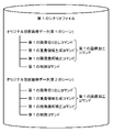
- the user first activates the scenario file creation window by operating the external controller 8 (S101).
- the user selects the original projection image data (first scene), which is the source of the first scene total projection image 16A, and the second scene total projection image 16B.
- the original projection image data (second scene) that is the basis of is registered (S102).
- the user a) generates a first image processing command for the first scene, and converts the generated first image processing command to the original projection image data (first scene). and b) generating a second image processing command for the first scene, associating the generated second image processing command with the original projection image data (first scene), and c ) generating a first image processing command for the second scene, linking the generated first image processing command with the original projection image data (second scene); A second image processing command is generated, and the generated second image processing command is associated with the original projection image data (second scene) (S103).
- the user performs an operation to enlarge or reduce the range of cutting out the first projection image 12A (second projection image 14A) from the original projection image for the first scene. can generate a first image processing command (second image processing command) for the first scene.
- the user performs an operation to enlarge or reduce the range of cutting out the first projection image 12B (second projection image 14B) from the original projection image for the second scene.
- the first image processing command (second image processing command) for the second scene can be generated.
- the original projection image for the first scene is displayed on the scenario file creation window based on the photographed data obtained by photographing the front surface of the set 32 with a camera (not shown).
- a first image processing command (second image processing command) for the first scene may be generated by automatically cutting out the projected image 12A (second projected image 14A).
- a first projection image 12B (second projection image 14B) is generated from the original projection image for the second scene on the scenario file creation window based on the photographed data obtained by photographing the front of the stage background 34 with the camera. may be automatically extracted to generate the first image processing command (second image processing command) for the second scene.
- step S103 the user a) generates a first control command for the first scene on the scenario creation window, and converts the generated first control command to the original projection image data (first scene). and b) generating a second control command for the first scene, associating the generated second control command with the original projection image data (first scene), and c) generating a first control command for the second scene, linking the generated first control command with the original projection image data (second scene); and d) second control for the second scene.
- a command is generated, and the generated second control command is associated with the original projection image data (second scene) (S104).
- the first scenario file and the second scenario file are completed (S105).
- the user selects the first projector 4 and the second projector 6 as projectors to be controlled on the scenario creation window (S106).
- the external controller 8 transmits the first scenario file and the second scenario file respectively to the media server 10 of the first projector 4 and the media server 11 of the second projector 6 (S107).
- the reception unit 22 of the media server 10 of the first projector 4 receives the first scenario file from the external controller 8 (S108).
- reception unit 22 of the media server 11 of the second projector 6 receives the second scenario file from the external controller 8 (S109).
- the generation unit 26 of the media server 10 of the first projector 4 generates the first projection image data and the first control signal for the first scene and the first control signal for the second scene based on the first scenario file. to generate first projection image data and a first control signal (S110).
- the generation unit 26 of the media server 11 of the second projector 6 generates the second projection image data for the first scene, the second control signal, and the second projection image data based on the second scenario file. Second projection image data for the scene and second control signals are generated (S111).
- the transmission unit 28 of the media server 10 of the first projector 4 transmits the first projection image data for the first scene and the first control signal to the projector unit 36 of the first projector 4 . Also, the transmission unit 28 of the media server 11 of the second projector 6 transmits the second projection image data for the first scene and the second control signal to the projector unit 36 of the second projector 6 .
- the projector unit 36 of the first projector 4 projects the first projection image 12A in the first scene based on the first projection image data for the first scene and the first control signal from the media server 10.
- the image is projected onto the front surface of the prop 32 (S112).
- the projector unit 36 of the second projector 6 performs the second projection image data in the first scene based on the second projection image data for the first scene and the second control signal from the media server 11 .
- the projected image 14A is projected onto the front surface of the prop 32 (S113).
- an overall projection image 16A for the first scene is projected onto the front surface of the prop 32 (see (a) of FIG. 6).
- the transmission unit 28 of the media server 10 of the first projector 4 transmits the first projection image data and the first control signal for the second scene to the projector unit of the first projector 4. 36. Also, the transmission unit 28 of the media server 11 of the second projector 6 transmits the second projection image data for the second scene and the second control signal to the projector unit 36 of the second projector 6 .
- the projector unit 36 of the first projector 4 projects the first projection image 12B in the second scene based on the first projection image data for the second scene and the first control signal from the media server 10. Project on the front of the stage background 34 (S114). At the same time, the projector unit 36 of the second projector 6 performs the second projection image data in the second scene based on the second projection image data for the second scene from the media server 11 and the second control signal.
- the projected image 14B is projected in front of the stage background 34 (S115). As a result, in the second scene, the overall projection image 16B for the second scene is projected in front of the stage background 34 (see (b) of FIG. 6).
- the projection system 2 projects the first projected image 12 and the second projected image 14 such that the edges of the first projected image 12 and the edges of the second projected image 14 overlap. It is a system that projects onto a projection plane 18 .
- the projection system 2 comprises a first projector 4 that projects a first projection image 12 onto a projection plane 18 and a second projector 6 that projects a second projection image 14 onto the projection plane 18 .
- the first projector 4 is associated with the first projection image data indicating the first projection image 12 extracted from the original projection image 20 and the first projection image data, and drives the first projector 4.
- the second projector 6 is associated with the second projection image data representing the second projection image 14 extracted from the original projection image 20 and the second projection image data, and drives the second projector 6.
- the first projector is configured to project the first projection image 12 onto the projection surface 18 in a projection mode (for example, focus, zoom, brightness of the light source, etc.) according to the first projection image 12. 4 can be controlled. Further, the driving of the second projector 6 can be controlled so as to project the second projection image 14 onto the projection plane 18 in a projection mode corresponding to the second projection image 14 . As a result, even when a plurality of projectors including the first projector 4 and the second projector 6 are used, the driving of each projector can be easily controlled.
- a projection mode for example, focus, zoom, brightness of the light source, etc.
- the first projector 4 has the receiving section 22 that receives the first command data from the external controller 8 .
- the second projector 6 has a receiving section 22 that receives second command data from the external controller 8 .
- the first command data is a first image clipping command that instructs the media server 10 of the first projector 4 to clip the first projected image 12 from the original projected image 20 to generate first projected image data. and a first control command instructing the media server 10 of the first projector 4 to generate a first control signal.
- the second command data is a second image clipping command instructing the media server 11 of the second projector 6 to clip the second projected image 14 from the original projected image 20 to generate the second projected image data.
- the media server 10 of the first projector 4 generates first projection image data and a first control signal based on the first command data.
- the media server 11 of the second projector 6 generates second projection image data and a second control signal based on the second command data.
- the first projection image data and the first control signal can be easily generated based on the first command data, and the second projection image data and the first control signal can be generated based on the second command data.
- the second control signal can be easily generated.
- the first command data includes a plurality of first image clipping commands and a plurality of first control commands respectively corresponding to the plurality of types of original projection images 20 .
- the second command data includes a plurality of second image clipping commands and a plurality of second control commands respectively corresponding to the plurality of types of original projection images 20 .
- the first projection image data and the first control signal can be easily generated based on the first command data for each type of the original projection image 20 (for example, each scene).
- the second projection image data and the second control signal can be easily generated based on the two command data.
- the plurality of first image clipping commands and the plurality of first control commands are commands for controlling the first projector 4 at different timings.
- the plurality of first image clipping commands are commands with the same content.
- the plurality of first control commands are commands with different contents.
- the plurality of second image clipping commands and the plurality of second control commands are commands for controlling the second projector 6 at different timings.
- the plurality of second image clipping commands are commands with the same content.
- the plurality of second control commands are commands with different contents.
- the first image clipping command and the second image clipping command each include position coordinates in the original projection image 20 .
- the position coordinates of the first image cutout command and the position coordinates of the second image cutout command are different from each other.
- control method of the projection system 2 is such that the first projection image 12 and the second projection image 14 are projected using the first projector 4 and the second projector 6, respectively.
- image 12 and the second projection image 14 are projected onto the projection plane 18 so that the edges of the image 12 and the edges of the second projection image 14 overlap each other.
- the control method of the projection system 2 includes (a) first projection image data showing a first projection image 12 cut out from the original projection image 20, and showing a second projection image 14 cut out from the original projection image 20.
- second projection image data and a second projection image data associated with the second projection image data for controlling the driving of the second projector 6; 2 to the second projector 6.
- Modification 1 [2-1. Outline of Projection System] An outline of a projection system 2A according to Modification 1 will be described with reference to FIG.
- FIG. 8 is a diagram showing an outline of a projection system 2A according to Modification 1. As shown in FIG. In addition, in this modification, the same code
- the media server 10 and the media server 11 are built in the first projector 4 and the second projector 6, respectively.
- the first media server 10A and the second media server 11A are connected to the first projector 4A and the second projector 6A, respectively. It is connected so that it can communicate from the outside.
- Both the first projector 4A and the second projector 6A have only the function of the projector section 36 (see FIG. 3) described in the above embodiment.
- FIG. 9 is a block diagram showing the functional configuration of the first media server 10A (second media server 11A) according to Modification 1. As shown in FIG.
- Each of the first media server 10A and the second media server 11A has a receiving unit 22, a storage unit 24, a generating unit 26, and a transmitting unit 28 as functional configurations, as in the above embodiment. is doing.
- the transmission unit 28 of the first media server 10A transmits the first projection image data for the first scene and the first control signal generated by the generation unit 26 of the first media server 10A, and the second 1st projection image data for the scene 1 and the first control signal are sequentially transmitted to the first projector 4A.
- the first projection image data is transmitted to the image input terminal 48 of the first projector 4A.
- the first control signal is transmitted to the network terminal 50 of the first projector 4A.
- the image input terminal 48 is, for example, an HDMI (registered trademark) (High-Definition Multimedia Interface) terminal or the like
- the network terminal 50 is, for example, a LAN terminal or the like.
- the transmission unit 28 of the second media server 11A transmits the second projection image data for the first scene and the second control signal generated by the generation unit 26 of the second media server 11A, and The second projection image data for the second scene and the second control signal are sequentially transmitted to the second projector 6A. Specifically, the second projection image data is transmitted to the image input terminal 48 of the second projector 6A. Also, the second control signal is transmitted to the network terminal 50 of the second projector 6A.
- FIG. 10 is a sequence diagram showing the operation flow of the projection system 2A according to Modification 1. As shown in FIG.
- steps S201 to S205 are first executed in the same manner as steps S101 to S105 in FIG. 7 described in the above embodiment.
- the user selects the first media server 10A and the second media server 11A as destinations of the first scenario file and the second scenario file on the scenario creation window ( S206).
- step S207 is performed like step S106 of FIG.
- the external controller 8 transmits the first scenario file and the second scenario file respectively to the first media server 10A and the second media server 11A (S208).
- the receiving unit 22 of the first media server 10A receives the first scenario file from the external controller 8 (S209). Also, the receiving unit 22 of the second media server 11A receives the second scenario file from the external controller 8 (S210).
- the generation unit 26 of the first media server 10A generates the first projection image data and the first control signal for the first scene, and the first projection image data for the second scene, based on the first scenario file. projection image data and a first control signal (S211). Also, the generation unit 26 of the second media server 11A generates the second projection image data and the second control signal for the first scene, and the second projection image data for the second scene, based on the second scenario file. Second projection image data and a second control signal are generated (S212).
- the transmission unit 28 of the first media server 10A transmits the first projection image data for the first scene and the first control signal to the first projector 4A (S213). Also, the transmission unit 28 of the second media server 11A transmits the second projection image data for the first scene and the second control signal to the second projector 6A (S214).
- the first projector 4A Based on the first projection image data for the first scene and the first control signal from the first media server 10A, the first projector 4A, as shown in FIG. In the first scene, the first projection image 12A is projected onto the front surface of the prop 32 (S215). At the same time, the second projector 6A operates as shown in FIG. As shown, the second projection image 14A is projected in front of the prop 32 in the first scene (S216). As a result, in the first scene, the entire projection image 16A for the first scene is projected on the front surface of the setting 32 .
- the transmission unit 28 of the first media server 10A transmits the first projection image data for the second scene and the first control signal to the first projector 4A (S217). Also, the transmission unit 28 of the second media server 11A transmits the second projection image data for the second scene and the second control signal to the second projector 6A (S218).
- the first projector 4A Based on the first projection image data for the second scene and the first control signal from the first media server 10A, the first projector 4A, as shown in FIG. In the second scene, the first projection image 12B is projected in front of the stage background 34 (S219). At the same time, the second projector 6A operates as shown in FIG. As shown, a second projected image 14B is projected in front of the stage background 34 in the second scene (S220). As a result, the entire projection image 16B for the second scene is projected in front of the stage background 34 in the second scene.
- the timing for transmitting each projection image data and each control signal in steps S213 and S214 described above and the timing for transmitting each projection image data and each control signal in steps S217 and S218 described above are determined by the first scenario file. and the second scenario file.
- the first media server 10A and the second media server 11A are configured separately from the first projector 4A and the second projector 6A, respectively. 4A and a second projector 6A.
- FIG. 11 is a diagram showing an outline of a projection system 2B according to Modification 2.
- symbol is attached
- first media server 10A and second media server 11A are arranged corresponding to the first projector 4A and the second projector 6A, respectively.
- one media server 10B is arranged for the first projector 4A and the second projector 6A.
- both the first projector 4A and the second projector 6A have only the function of the projector unit 36 (see FIG. 3) described in the above embodiment, as in the first modification.
- FIG. 12 is a block diagram showing the functional configuration of a media server 10B according to Modification 2. As shown in FIG.
- the media server 10B has a receiving unit 22, a storage unit 24, a generating unit 26, and a transmitting unit 28 as functional configurations, as in the above embodiment.
- the transmission unit 28 transmits the first projection image data for the first scene and the first control signal, and the first projection image data for the second scene and the first control signal generated by the generation unit 26 .
- Control signals are sequentially transmitted to the first projector 4A.
- the first projection image data is transmitted to the image input terminal (not shown) of the first projector 4A.
- the first control signal is transmitted to a network terminal (not shown) of the first projector 4A.
- the transmission unit 28 generates the second projection image data for the first scene and the second control signal, and the second projection image data for the second scene and the second control signal generated by the generation unit 26 .
- 2 control signals are sequentially transmitted to the second projector 6A.
- the second projection image data is transmitted to the image input terminal (not shown) of the second projector 6A.
- the second control signal is transmitted to a network terminal (not shown) of the second projector 6A.
- FIG. 13 is a sequence diagram showing the operation flow of the projection system 2B according to Modification 2. As shown in FIG.
- steps S301 to S306 are executed in the same manner as steps S101 to S106 in FIG. 7 described in the above embodiment.
- the external controller 8 transmits the first scenario file and the second scenario file to the media server 10B (S307).
- the receiving unit 22 of the media server 10B receives the first scenario file and the second scenario file from the external controller 8 (S308).
- the generation unit 26 of the media server 10B generates the first projection image data and the first control signal for the first scene and the first projection image for the second scene based on the first scenario file. Data and a first control signal are generated (S309). Furthermore, based on the second scenario file, the generating unit 26 generates the second projection image data and the second control signal for the first scene, and the second projection image data and the second scene for the second scene. A second control signal is generated (S309).
- the transmission unit 28 of the media server 10B transmits the first projection image data for the first scene and the first control signal to the first projector 4A, and transmits the second projection image for the first scene.
- the data and the second control signal are transmitted to the second projector 6A (S310).
- the first projector 4A Based on the first projection image data for the first scene and the first control signal from the media server 10B, the first projector 4A performs the first projection as shown in FIG. In the scene, the first projection image 12A is projected onto the front surface of the prop 32 (S311). At the same time, the second projector 6A, based on the second projection image data for the first scene and the second control signal from the media server 10B, as shown in FIG. , the second projection image 14A is projected onto the front surface of the prop 32 in the first scene (S312). As a result, in the first scene, the entire projection image 16A for the first scene is projected on the front surface of the setting 32 .
- the transmission unit 28 of the media server 10B transmits the first projection image data for the second scene and the first control signal to the first projector 4A, and The second projection image data for the projector and the second control signal are transmitted to the second projector 6A (S313).
- the first projector 4A Based on the first projection image data for the second scene and the first control signal from the media server 10B, the first projector 4A performs the second projection as shown in FIG. In the scene, the first projection image 12B is projected in front of the stage background 34 (S314).
- the second projector 6A based on the second projection image data for the second scene and the second control signal from the media server 10B, as shown in FIG. , the second projection image 14B is projected in front of the stage background 34 in the second scene (S315).
- the entire projection image 16B for the second scene is projected in front of the stage background 34 in the second scene.
- the timing for transmitting each projection image data and each control signal in step S310 described above and the timing for transmitting each projection image data and each control signal in step S313 described above are determined by the first scenario file and the second scenario file. It shall be specified by the scenario file.
- one media server 10B is arranged for the first projector 4A and the second projector 6A, so the configuration of the projection system 2B can be further simplified.
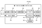
- FIG. 14 is a block diagram showing the functional configuration of the first projector 4C (second projector 6C) of the projection system 2C according to Modification 3.
- the projection system 2C has a first projector 4C and a second projector 6C, and the first and second projectors 4C and 6C each have a storage unit for storing first and second control signals, It is different from the projection system 2A according to Modification 1.
- symbol is attached
- the first and second projectors 4C, 6C of the projection system 2C, as shown in FIG. 14, have storage units 52 that store first and second control signals, respectively.
- the storage unit 52 stores the first control signal (second control signal) transmitted via the network terminal 50 from the transmission unit 28 of the first media server 10A (second media server 11A).
- the projection system 2C is such that the first and second scenario files do not contain the first and second control commands, respectively, and the first and second control commands are provided separately from the first and second scenario files. It is different from the projection system 2A of Modified Example 1 in that it is transmitted to the first media server 10A and the second media server 11A, respectively.
- 15 and 16 show the configurations of first and second scenario files received by the first and second media servers 10A, 11A from the external controller 8, respectively.
- the first scenario file includes original projection image data for the first and second scenes, a first image clipping command, a first superimposed area generation command, and a first image geometric correction command and does not include the first control command.
- the second scenario file includes original projection image data for the first and second scenes, a second image clipping command, a second superimposition area generation command, and a second image geometric correction command and does not include the second control command.
- FIG. 17 is a sequence diagram showing the operation flow of the projection system 2C according to Modification 3. As shown in FIG.
- steps S401 to S407 are executed in the same manner as steps S201 to S207 in FIG. 10 described in Modification 1 above.
- the first and second scenario files completed in step S405 do not contain the first and second control commands.
- the external controller 8 transmits the first scenario file and the first control command to the first media server 10A, and transmits the second scenario file and the second control command to the second media server 11A. (S408).
- the receiving unit 22 of the first media server 10A receives the first scenario file and the first control command from the external controller 8 (S409). Also, the receiving unit 22 of the second media server 11A receives the second scenario file and the second control command from the external controller 8 (S410).
- the generation unit 26 of the first media server 10A generates first projection image data for first and second scenes based on the first scenario file, and generates first and second projection image data based on the first control command.
- a first control signal for a second scene and a signal for operating the first control signal are generated (S411).
- the generation unit 26 of the second media server 11A generates second projection image data for the first and second scenes based on the second scenario file, and generates second projection image data for the first and second scenes based on the second control command.
- a second control signal for the first and second scenes and a signal to operate the second control signal are generated (S412).
- the transmission unit 28 of the first media server 10A transmits the first control signals for the first and second scenes to the first projector 4C (S413). Also, the transmission unit 28 of the second media server 11A transmits the second control signals for the first and second scenes to the second projector 6C (S414).
- the first projector 4C stores the received first control signals for the first and second scenes in the storage unit 52 of the first projector 4C (S415).
- the second projector 6C also stores the received second control signals for the first and second scenes in the storage unit 52 of the second projector 6C (S416).
- the transmission unit 28 of the first media server 10A transmits the first projection image data for the first scene and the signal for operating the first control signal to the first projector 4C (S417). Also, the transmission unit 28 of the second media server 11A transmits the second projection image data for the first scene and a signal for operating the second control signal to the second projector 6C (S418).
- the first projector 4C operates the first control signal stored in the storage unit 52 in accordance with the signal for operating the first control signal for the first scene from the first media server 10A, and operates the first control signal for the first scene. Based on the first projection image data for the first scene and the first control signal, as shown in FIG. (S419).
- the second projector 6C operates the second control signal stored in the storage unit 52 according to the signal for operating the second control signal for the first scene from the second media server 11A.
- the second projection image 14A is enlarged in the first scene as shown in FIG. Project on the front surface of the tool 32 (S420).
- the entire projection image 16A for the first scene is projected on the front surface of the setting 32 .
- the transmission unit 28 of the first media server 10A transmits the first projection image data for the second scene and a signal for operating the first control signal to the first projector 4C. (S421). Also, the transmission unit 28 of the second media server 11A transmits the second projection image data for the second scene and a signal for operating the second control signal to the second projector 6C (S422).
- the first projector 4C operates the first control signal stored in the storage unit 52 in accordance with the signal for operating the first control signal for the second scene from the first media server 10A, Based on the first projection image data for the first scene and the first control signal, the first projection image 12B is projected in front of the stage background 34 in the second scene, as shown in FIG. (S423).
- the second projector 6C operates the second control signal stored in the storage unit 52 according to the signal for operating the second control signal for the second scene from the second media server 11A.
- the second projection image 14B is set in the second scene as shown in FIG. Project on the front of the background 34 (S424).
- the entire projection image 16B for the second scene is projected in front of the stage background 34 in the second scene.
- timing for transmitting the signal for operating each projection image data and each control signal in steps S417 and S418 described above and the signal for operating each projection image data and each control signal in steps S421 and S422 described above are transmitted. Assume that the timing is defined by the first scenario file and the second scenario file.
- FIG. 18 is a block diagram showing the functional configuration of the first projector 4C (second projector 6C) of the projection system 2D according to Modification 4.
- the projection system 2D is similar to the projection system 2C according to Modification 3 in that it has one media server 10B described in Modification 2 for the first and second projectors 4C and 6C described in Modification 3.
- one media server 10B transmits the first projection image data, the first control signal, and the signal for operating the first control signal to the first projector 4C,
- the second projection image data, the second control signal, and the signal for operating the second control signal are transmitted to the second projector 6C.
- symbol is attached
- FIG. 19 is a sequence diagram showing the operation flow of the projection system 2D according to Modification 4. As shown in FIG.
- steps S501 to S506 are executed in the same way as steps S301 to S306 in FIG. 13 described in Modification 2 above.
- the first and second scenario files completed in step S505 do not contain the first and second control commands.
- the external controller 8 transmits the first scenario file, the second scenario file, the first control command, and the second control command to the media server 10B (S507).
- the receiving unit 22 of the media server 10B receives the first scenario file, second scenario file, first control command, and second control command from the external controller 8 (S508).
- the generation unit 26 of the media server 10B generates first projection image data for first and second scenes based on the first scenario file, and generates first and second projection image data based on the second scenario file. generating second projection image data for the scene; generating a first control signal for the first and second scenes based on the first control command and a signal for operating the first control signal; A second control signal for the first and second scenes and a signal for operating the second control signal are generated based on the second control command (S509).
- the transmission unit 28 of the media server 10B transmits first control signals for the first and second scenes to the first projector 4C, and transmits second control signals for the first and second scenes to the second control signal. is transmitted to the projector 6C (S510).
- the first projector 4C stores the received first control signal in the storage unit 52 of the first projector 4C (S511).
- the second projector 6C also stores the received second control signal in the storage unit 52 of the second projector 6C (S512).
- the transmission unit 28 of the media server 10B transmits the first projection image data for the first scene and the signal for operating the first control signal to the first projector 4C, and transmits the first projection image data for the first scene and the first control signal for the first scene. 2 and a signal for operating the second control signal are transmitted to the second projector 6C (S513).
- the first projector 4C operates the first control signal stored in the storage unit 52 in accordance with the signal for operating the first control signal for the first scene from the media server 10B, and operates the first control signal for the first scene.
- the first projection image 12A is projected onto the front surface of the prop 32 in the first scene, as shown in FIG. (S514).
- the second projector 6C activates the second control signal stored in the storage unit 52 according to the signal for activating the second control signal for the first scene from the media server 10B.
- the second projection image data for one scene and the second control signal as shown in FIG. Project on the front (S515).
- the entire projection image 16A for the first scene is projected on the front surface of the setting 32 .
- the transmission unit 28 of the media server 10B transmits the first projection image data for the second scene and a signal for operating the first control signal to the first projector 4C, and A signal for operating the second projection image data for the second scene and the second control signal are transmitted to the second projector 6C (S516).
- the first projector 4C operates the first control signal stored in the storage unit 52 in accordance with the signal for operating the first control signal for the second scene from the media server 10B, and operates the first control signal for the second scene. Based on the first projection image data and the first control signal, the first projection image 12B is projected in front of the stage background 34 in the second scene, as shown in FIG. (S517).
- the second projector 6C operates the second control signal stored in the storage unit 52 in accordance with the signal for operating the second control signal for the second scene from the media server 10B. Based on the second projection image data for scene 2 and the second control signal, as shown in FIG. Project on the front (S518). As a result, the entire projection image 16B for the second scene is projected in front of the stage background 34 in the second scene.
- timing for transmitting the signal for operating each projection image data and each control signal in step S513 described above and the timing for transmitting the signal for operating each projection image data and each control signal in step S516 described above are determined by the It is defined by one scenario file and a second scenario file.
- the projection system 2 (2A, 2B) includes two projectors (the first projector 4 (4A) and the second projector 6 (6A)), but the present invention is not limited to this. , may include three or more projectors.
- each of the first scenario file and the second scenario file includes various commands corresponding to two scenes.
- Various commands corresponding to each scene may be included.
- the controlled object by the scenario file is the projector
- the transmission units 28 of the media server 10 and the media server 11 may be connected to devices to be controlled other than projectors, such as lighting devices, speakers, and microphones (hereinafter referred to as "other devices").
- the data included in the first scenario file (second scenario file) include, in addition to the original projection image data, lighting control data for controlling the lighting device and audio data for outputting audio from the speaker. may contain These lighting control data and audio data are set in association with the original projection image data.
- the first scenario file contains lighting control data and audio data set for each scene, like the original projection image data.
- the lighting control data includes, for example, a command for turning on/off the power of the lighting device, a voltage value applied to the lighting device, a command for instructing the lighting color, and the like.
- the audio data includes, for example, an audio signal, a command for instructing volume, and the like.
- Other examples of other devices controlled by the first scenario file (second scenario file) include, for example, curtains as blackout curtains for stages, firearms for stage production, devices that generate fog and smoke, It may be a mirror ball or a prop driven by an actuator.
- the first scenario file further includes other device commands for controlling devices different from the projectors including the first projector 4 and the second projector 6, and the other device commands are the original projected images.
- the first scenario file may include a plurality of other device commands, and each of the plurality of other device commands may be associated with a plurality of types of original projection images.
- each component may be configured with dedicated hardware or realized by executing a software program suitable for each component.
- Each component may be realized by reading and executing a software program recorded in a recording medium such as a hard disk or a semiconductor memory by a program execution unit such as a CPU or processor.
- some or all of the functions of the projection system 2 (2A, 2B) according to the above embodiments and the like may be implemented by a processor such as a CPU executing a program.
- the projection system of the present disclosure is applicable, for example, as a multi-projection system used on theater stages.
Abstract
Description
[1-1.投影システムの概要]
まず、図1及び図2を参照しながら、実施の形態に係る投影システム2の概要について説明する。図1は、実施の形態に係る投影システム2の概要を示す図である。図2は、実施の形態に係る投影システム2により投影される第1の投影画像12、第2の投影画像14及び全体投影画像16の一例を示す図である。 (Embodiment)
[1-1. Outline of Projection System]
First, an outline of a
次に、図3~図6を参照しながら、実施の形態に係る第1のプロジェクタ4及び第2のプロジェクタの各メディアサーバの機能構成について説明する。図3は、実施の形態に係るメディアサーバ10(11)の機能構成を示すブロック図である。図4は、実施の形態に係る第1のシナリオファイルの一例を示す図である。図5は、実施の形態に係る第2のシナリオファイルの一例を示す図である。図6は、実施の形態に係る投影システム2の適用例を示す図である。 [1-2. Functional Configuration of Media Server]
Next, the functional configuration of each media server of the
図7を参照しながら、実施の形態に係る投影システム2の動作について説明する。図7は、実施の形態に係る投影システム2の動作の流れを示すシーケンス図である。 [1-3. Operation of projection system]
The operation of the
本実施の形態では、投影システム2は、第1の投影画像12及び第2の投影画像14を、第1の投影画像12の端部と第2の投影画像14の端部とが重なり合うように投影面18に投影するシステムである。投影システム2は、第1の投影画像12を投影面18に投影する第1のプロジェクタ4と、第2の投影画像14を投影面18に投影する第2のプロジェクタ6とを備える。第1のプロジェクタ4は、オリジナル投影画像20から切り出した第1の投影画像12を示す第1の投影画像データ、及び、第1の投影画像データと紐付けられ且つ第1のプロジェクタ4の駆動を制御するための第1の制御信号を取得する。第2のプロジェクタ6は、オリジナル投影画像20から切り出した第2の投影画像14を示す第2の投影画像データ、及び、第2の投影画像データと紐付けられ且つ第2のプロジェクタ6の駆動を制御するための第2の制御信号を取得する。 [1-4. effect]
In this embodiment, the
[2-1.投影システムの概要]
図8を参照しながら、変形例1に係る投影システム2Aの概要について説明する。図8は、変形例1に係る投影システム2Aの概要を示す図である。なお、本変形例において、上記実施の形態と同一の構成要素には同一の符号を付して、その説明を省略する。 (Modification 1)
[2-1. Outline of Projection System]
An outline of a
図9を参照しながら、変形例1に係る第1のメディアサーバ10A及び第2のメディアサーバ11Aの各機能構成について説明する。図9は、変形例1に係る第1のメディアサーバ10A(第2のメディアサーバ11A)の機能構成を示すブロック図である。 [2-2. Functional configuration of each media server]
Each functional configuration of the
図10を参照しながら、変形例1に係る投影システム2Aの動作について説明する。図10は、変形例1に係る投影システム2Aの動作の流れを示すシーケンス図である。 [2-3. Operation of projection system]
The operation of the
本変形例では、第1のメディアサーバ10A及び第2のメディアサーバ11Aをそれぞれ、第1のプロジェクタ4A及び第2のプロジェクタ6Aとは別体に構成することにより、汎用のプロジェクタを第1のプロジェクタ4A及び第2のプロジェクタ6Aとして用いることができる。 [2-4. effect]
In this modified example, the
[3-1.投影システムの概要]
図11を参照しながら、変形例2に係る投影システム2Bの概要について説明する。図11は、変形例2に係る投影システム2Bの概要を示す図である。なお、本変形例において、上記実施の形態及び変形例1と同一の構成要素には同一の符号を付して、その説明を省略する。 (Modification 2)
[3-1. Outline of Projection System]
An outline of a
図12を参照しながら、変形例2に係るメディアサーバ10Bの機能構成について説明する。図12は、変形例2に係るメディアサーバ10Bの機能構成を示すブロック図である。 [3-2. Functional Configuration of Media Server]
A functional configuration of a
図13を参照しながら、変形例2に係る投影システム2Bの動作について説明する。図13は、変形例2に係る投影システム2Bの動作の流れを示すシーケンス図である。 [3-3. Operation of projection system]
The operation of the
本変形例では、第1のプロジェクタ4A及び第2のプロジェクタ6Aに対して1台のメディアサーバ10Bが配置されているので、投影システム2Bの構成をより簡素化することができる。 [3-4. effect]
In this modified example, one
[4-1.投影システムの構成]
図14~図16を参照しながら、変形例3に係る投影システム2Cの機能構成について説明する。図14は、変形例3に係る投影システム2Cの第1のプロジェクタ4C(第2のプロジェクタ6C)の機能構成を示すブロック図である。投影システム2Cは、第1のプロジェクタ4C及び第2のプロジェクタ6Cを有し、第1及び第2のプロジェクタ4C,6Cがそれぞれ第1及び第2の制御信号を記憶する記憶部を有する点で、変形例1に係る投影システム2Aと異なる。なお、本変形例において、上記実施の形態及び変形例1と同一の構成要素には同一の符号を付して、その説明を省略する。 (Modification 3)
[4-1. Configuration of Projection System]
A functional configuration of a projection system 2C according to Modification 3 will be described with reference to FIGS. 14 to 16. FIG. FIG. 14 is a block diagram showing the functional configuration of the
図17を参照しながら、変形例3に係る投影システム2Cの動作について説明する。図17は、変形例3に係る投影システム2Cの動作の流れを示すシーケンス図である。 [4-2. Operation of projection system]
The operation of the projection system 2C according to Modification 3 will be described with reference to FIG. FIG. 17 is a sequence diagram showing the operation flow of the projection system 2C according to Modification 3. As shown in FIG.
本変形例では、第1及び第2のメディアサーバ10A,11Aをそれぞれ第1及び第2のプロジェクタ4C,6Cとは別体に構成する場合に、予め第1及び第2の制御信号をそれぞれ第1及び第2のプロジェクタ4C,6Cに記憶させておくことにより、第1及び第2のメディアサーバ10A,11Aから第1及び及び第2のプロジェクタ4C,6Cへのデータ送信の負荷を軽減することができる。 [2-4. effect]
In this modified example, when the first and
[5-1.投影システムの構成]
図18を参照しながら、変形例4に係る投影システム2Dの機能構成について説明する。図18は、変形例4に係る投影システム2Dの第1のプロジェクタ4C(第2のプロジェクタ6C)の機能構成を示すブロック図である。投影システム2Dは、変形例3で説明した第1及び第2のプロジェクタ4C,6Cに対して、変形例2で説明した1台のメディアサーバ10Bを有する点で、変形例3に係る投影システム2Cと異なる。即ち、投影システム2Dでは、1台のメディアサーバ10Bが、第1のプロジェクタ4Cに対して、第1の投影画像データ、第1の制御信号及び第1の制御信号を動作させる信号を送信し、第2のプロジェクタ6Cに対して、第2の投影画像データ、第2の制御信号及び第2の制御信号を動作させる信号を送信する。なお、本変形例において、上記実施の形態、変形例2及び変形例3と同一の構成要素には同一の符号を付して、その説明を省略する。 (Modification 4)
[5-1. Configuration of Projection System]
A functional configuration of a projection system 2D according to
図19を参照しながら、変形例4に係る投影システム2Dの動作について説明する。図19は、変形例4に係る投影システム2Dの動作の流れを示すシーケンス図である。 [5-2. Operation of projection system]
The operation of the projection system 2D according to
本変形例では、メディアサーバ10Bを第1及び第2のプロジェクタ4C、6Cとは別体に構成する場合に、予め第1及び第2の制御信号をそれぞれ第1及び第2のプロジェクタ4C,6Cに記憶させておくことにより、メディアサーバ10Bから第1及び及び第2のプロジェクタ4C,6Cへのデータ送信の負荷を軽減することができる。また、第1及び第2のプロジェクタ4C,6Cに対して1台のメディアサーバ10Bが配置されているので、投影システム2Dの構成をより簡素化することができる。 [3-4. effect]
In this modified example, when the
以上のように、本出願において開示する技術の例示として、上記実施の形態及び各変形例を説明した。しかしながら、本開示における技術は、これに限定されず、適宜、変更、置き換え、付加、省略などを行った実施の形態にも適用可能である。また、上記実施の形態及び各変形例で説明した各構成要素を組み合わせて、新たな実施の形態とすることも可能である。 (other modifications, etc.)
As described above, the above embodiments and modifications have been described as examples of the technology disclosed in the present application. However, the technology in the present disclosure is not limited to this, and can be applied to embodiments in which modifications, replacements, additions, omissions, etc. are made as appropriate. Further, it is also possible to combine the constituent elements described in the above embodiment and each modified example to form a new embodiment.
4,4A,4C 第1のプロジェクタ
6,6A,6C 第2のプロジェクタ
8 外部コントローラ
10,10B,11 メディアサーバ
10A 第1のメディアサーバ
11A 第2のメディアサーバ
12,12A,12B 第1の投影画像
12a,12Aa,12Ba 重畳領域
12b,12Ab,12Bb 他の領域
13 ネットワークスイッチ
14,14A,14B 第2の投影画像
14a,14Aa,14Ba 重畳領域
14b,14Ab,14Bb 他の領域
16,16A,16B 全体投影画像
18 投影面
20 オリジナル投影画像
22 受信部
24 記憶部
26 生成部
28 送信部
30 舞台
32 大道具
34 舞台背景
36 プロジェクタ部
38 画像受信部
40 CPU
42 FPGA
44 投影部
46 機能部
48 画像入力端子
50 ネットワーク端子
52 記憶部 2, 2A, 2B, 2C,
42 FPGAs
44
Claims (13)
- 第1の投影画像及び第2の投影画像を、前記第1の投影画像の端部と前記第2の投影画像の端部とが重なり合うように投影面に投影する投影システムであって、
前記第1の投影画像を前記投影面に投影する第1のプロジェクタと、
前記第2の投影画像を前記投影面に投影する第2のプロジェクタと、を備え、
前記第1のプロジェクタは、少なくとも1つのオリジナル投影画像から切り出した前記第1の投影画像を示す第1の投影画像データ、及び、前記第1の投影画像データと紐付けられ且つ前記第1のプロジェクタの駆動を制御するための第1の制御信号を取得し、
前記第2のプロジェクタは、前記少なくとも1つのオリジナル投影画像から切り出した前記第2の投影画像を示す第2の投影画像データ、及び、前記第2の投影画像データと紐付けられ且つ前記第2のプロジェクタの駆動を制御するための第2の制御信号を取得する
投影システム。 A projection system that projects a first projection image and a second projection image onto a projection plane such that edges of the first projection image and edges of the second projection image overlap,
a first projector that projects the first projection image onto the projection plane;
a second projector that projects the second projection image onto the projection plane;
The first projector includes: first projection image data representing the first projection image extracted from at least one original projection image; obtaining a first control signal for controlling the driving of the
The second projector provides: second projection image data representing the second projection image cut out from the at least one original projection image; A projection system that obtains a second control signal for controlling the driving of the projector. - 前記第1のプロジェクタは、外部コントローラから第1のコマンドデータを受信する第1の受信部を有し、
前記第2のプロジェクタは、前記外部コントローラから第2のコマンドデータを受信する第2の受信部を有し、
前記第1のコマンドデータは、
前記少なくとも1つのオリジナル投影画像から前記第1の投影画像を切り出して前記第1の投影画像データを生成することを前記第1のプロジェクタに指示する少なくとも1つの第1の画像切り出しコマンドと、
前記第1の制御信号を生成することを前記第1のプロジェクタに指示する少なくとも1つの第1の制御コマンドと、を含み、
前記第2のコマンドデータは、
前記少なくとも1つのオリジナル投影画像から前記第2の投影画像を切り出して前記第2の投影画像データを生成することを前記第2のプロジェクタに指示する少なくとも1つの第2の画像切り出しコマンドと、
前記第2の制御信号を生成するように前記第2のプロジェクタに指示する少なくとも1つの第2の制御コマンドと、を含み、
前記第1のプロジェクタは、前記第1のコマンドデータに基づいて前記第1の投影画像データ及び前記第1の制御信号を生成し、
前記第2のプロジェクタは、前記第2のコマンドデータに基づいて前記第2の投影画像データ及び前記第2の制御信号を生成する
請求項1に記載の投影システム。 The first projector has a first receiver that receives first command data from an external controller,
The second projector has a second receiver that receives second command data from the external controller,
The first command data is
at least one first image cropping command instructing the first projector to crop the first projected image from the at least one original projected image to generate the first projected image data;
at least one first control command instructing the first projector to generate the first control signal;
The second command data is
at least one second image cropping command instructing the second projector to crop the second projected image from the at least one original projected image to generate the second projected image data;
at least one second control command instructing the second projector to generate the second control signal;
The first projector generates the first projection image data and the first control signal based on the first command data,
2. The projection system according to claim 1, wherein said second projector generates said second projection image data and said second control signal based on said second command data. - 前記少なくとも1つのオリジナル投影画像は、複数種類のオリジナル投影画像であり、
前記少なくとも1つの第1の画像切り出しコマンドは、複数の第1の画像切り出しコマンドであり、前記複数の第1の画像切り出しコマンドは、前記複数種類のオリジナル投影画像にそれぞれ対応し、
前記少なくとも1つの第1の制御コマンドは、複数の第1の制御コマンドであり、前記複数の第1の制御コマンドは、前記複数種類のオリジナル投影画像にそれぞれ対応し、
前記少なくとも1つの第2の画像切り出しコマンドは、複数の第2の画像切り出しコマンドであり、前記複数の第2の画像切り出しコマンドは、前記複数種類のオリジナル投影画像にそれぞれ対応し、
前記少なくとも1つの第2の制御コマンドは、複数の第2の制御コマンドであり、前記複数の第2の制御コマンドは、前記複数種類のオリジナル投影画像にそれぞれ対応する
請求項2に記載の投影システム。 The at least one original projection image is a plurality of types of original projection images,
said at least one first image clipping command is a plurality of first image clipping commands, said plurality of first image clipping commands respectively corresponding to said plurality of types of original projection images;
the at least one first control command is a plurality of first control commands, the plurality of first control commands respectively corresponding to the plurality of types of original projection images;
the at least one second image clipping command is a plurality of second image clipping commands, the plurality of second image clipping commands corresponding to the plurality of types of original projection images, respectively;
3. The projection system according to claim 2, wherein said at least one second control command is a plurality of second control commands, and said plurality of second control commands respectively correspond to said plurality of types of original projection images. . - 前記複数の第1の画像切り出しコマンド及び前記複数の第1の制御コマンドはそれぞれ、時間的に異なるタイミングで前記第1のプロジェクタを制御するコマンドである
請求項3に記載の投影システム。 4. The projection system according to claim 3, wherein the plurality of first image cropping commands and the plurality of first control commands are commands for controlling the first projector at different timings. - 前記複数の第1の画像切り出しコマンドは、それぞれ同一の内容のコマンドであり、
前記複数の第1の制御コマンドは、それぞれ異なる内容のコマンドである
請求項4に記載の投影システム。 the plurality of first image clipping commands are commands having the same content,
5. The projection system according to claim 4, wherein the plurality of first control commands are commands with different contents. - 前記複数の第2の画像切り出しコマンド及び前記複数の第2の制御コマンドはそれぞれ、時間的に異なるタイミングで前記第2のプロジェクタを制御するコマンドである
請求項3に記載の投影システム。 4. The projection system according to claim 3, wherein the plurality of second image cropping commands and the plurality of second control commands are commands for controlling the second projector at different timings. - 前記複数の第2の画像切り出しコマンドは、それぞれ同一の内容のコマンドであり、
前記複数の第2の制御コマンドは、それぞれ異なる内容のコマンドである
請求項6に記載の投影システム。 the plurality of second image clipping commands are commands having the same content,
7. The projection system according to claim 6, wherein the plurality of second control commands are commands with different contents. - 前記少なくとも1つの第1の画像切り出しコマンド及び前記少なくとも1つの第2の画像切り出しコマンドはそれぞれ、前記少なくとも1つのオリジナル投影画像における位置座標を含み、
前記少なくとも1つの第1の画像切り出しコマンドの前記位置座標と前記少なくとも1つの第2の画像切り出しコマンドの前記位置座標とは互いに異なる
請求項2~7のいずれか1項に記載の投影システム。 the at least one first image cropping command and the at least one second image cropping command each include position coordinates in the at least one original projection image;
A projection system according to any one of claims 2 to 7, wherein said position coordinates of said at least one first image cropping command and said position coordinates of said at least one second image cropping command are different from each other. - 前記第1のコマンドデータは、さらに、前記第1のプロジェクタ及び前記第2のプロジェクタを含むプロジェクタとは異なる機器を制御するための少なくとも1つのその他機器用コマンドを含み、
前記少なくとも1つのその他機器用コマンドは、前記少なくとも1つのオリジナル投影画像に紐付けられている
請求項3に記載の投影システム。 the first command data further includes at least one other device command for controlling a device other than the projector including the first projector and the second projector;
4. The projection system according to claim 3, wherein said at least one other device command is associated with said at least one original projection image. - 前記少なくとも1つのその他機器用コマンドは、複数のその他機器用コマンドであり、
前記複数のその他機器用コマンドはそれぞれ、前記複数種類のオリジナル投影画像に紐付けられている
請求項9に記載の投影システム。 the at least one other device command is a plurality of other device commands,
10. The projection system according to claim 9, wherein the plurality of commands for other devices are respectively associated with the plurality of types of original projection images. - 前記第1のプロジェクタは、メディアサーバを介して、前記第1の投影画像データ、及び前記第1の制御信号を取得し、
前記第2のプロジェクタは、前記メディアサーバを介して、前記第2の投影画像データ、及び前記第2の制御信号を取得する
請求項1に記載の投影システム。 the first projector acquires the first projection image data and the first control signal via a media server;
2. The projection system according to claim 1, wherein said second projector acquires said second projection image data and said second control signal via said media server. - 前記第1のプロジェクタは、前記メディアサーバを介して、前記第1の制御信号を動作させる信号を取得し、
前記第2のプロジェクタは、前記メディアサーバを介して、前記第2の制御信号を動作させる信号を取得する
請求項11に記載の投影システム。 the first projector obtains a signal for operating the first control signal via the media server;
12. The projection system of claim 11, wherein the second projector obtains signals for operating the second control signals via the media server. - 第1の投影画像及び第2の投影画像をそれぞれ第1のプロジェクタ及び第2のプロジェクタを用いて、前記第1の投影画像の端部と前記第2の投影画像の端部とが重なり合うように投影面に投影する投影システムの制御方法であって、
(a)オリジナル投影画像から切り出した前記第1の投影画像を示す第1の投影画像データ、及び、前記オリジナル投影画像から切り出した前記第2の投影画像を示す第2の投影画像データを生成するステップと、
(b)前記第1の投影画像データ、及び、前記第1の投影画像データと紐付けられ且つ前記第1のプロジェクタの駆動を制御するための第1の制御信号を前記第1のプロジェクタに送信するステップと、
(c)前記第2の投影画像データ、及び、前記第2の投影画像データと紐付けられ且つ前記第2のプロジェクタの駆動を制御するための第2の制御信号を前記第2のプロジェクタに送信するステップと、を含む
投影システムの制御方法。 A first projection image and a second projection image are projected using a first projector and a second projector, respectively, so that an edge of the first projection image and an edge of the second projection image overlap each other. A control method for a projection system that projects onto a projection plane, comprising:
(a) generating first projection image data representing the first projection image cut out from the original projection image, and second projection image data representing the second projection image cut out from the original projection image; a step;
(b) transmitting the first projection image data and a first control signal linked with the first projection image data and for controlling driving of the first projector to the first projector; and
(c) transmitting the second projection image data and a second control signal associated with the second projection image data and for controlling driving of the second projector to the second projector; and a method of controlling a projection system.
Priority Applications (4)
| Application Number | Priority Date | Filing Date | Title |
|---|---|---|---|
| JP2023506988A JPWO2022196426A1 (en) | 2021-03-16 | 2022-03-08 | |
| EP22771178.5A EP4311225A1 (en) | 2021-03-16 | 2022-03-08 | Projection system and control method for projection system |
| CN202280021251.0A CN116982309A (en) | 2021-03-16 | 2022-03-08 | Projection system and control method of projection system |
| US18/367,106 US20230421735A1 (en) | 2021-03-16 | 2023-09-12 | Projection system and control method for projection system |
Applications Claiming Priority (2)
| Application Number | Priority Date | Filing Date | Title |
|---|---|---|---|
| JP2021-042851 | 2021-03-16 | ||
| JP2021042851 | 2021-03-16 |
Related Child Applications (1)
| Application Number | Title | Priority Date | Filing Date |
|---|---|---|---|
| US18/367,106 Continuation US20230421735A1 (en) | 2021-03-16 | 2023-09-12 | Projection system and control method for projection system |
Publications (1)
| Publication Number | Publication Date |
|---|---|
| WO2022196426A1 true WO2022196426A1 (en) | 2022-09-22 |
Family
ID=83320496
Family Applications (1)
| Application Number | Title | Priority Date | Filing Date |
|---|---|---|---|
| PCT/JP2022/009905 WO2022196426A1 (en) | 2021-03-16 | 2022-03-08 | Projection system and control method for projection system |
Country Status (5)
| Country | Link |
|---|---|
| US (1) | US20230421735A1 (en) |
| EP (1) | EP4311225A1 (en) |
| JP (1) | JPWO2022196426A1 (en) |
| CN (1) | CN116982309A (en) |
| WO (1) | WO2022196426A1 (en) |
Citations (6)
| Publication number | Priority date | Publication date | Assignee | Title |
|---|---|---|---|---|
| JPH09149296A (en) * | 1995-11-22 | 1997-06-06 | R D S Kk | Moving projector system |
| JP3216644B2 (en) * | 1990-03-09 | 2001-10-09 | オリンパス光学工業株式会社 | REAL IMAGE PROJECTION VIDEO REPRODUCING APPARATUS AND CONTROL SIGNAL FORMING APPARATUS FOR APPLICATION TO THE APPARATUS |
| JP2008051848A (en) * | 2006-08-22 | 2008-03-06 | Seiko Epson Corp | Display device, multi-display system, synchronous control method, synchronous control program, and recording medium |
| JP2014178503A (en) * | 2013-03-15 | 2014-09-25 | Casio Comput Co Ltd | Scenario data, projection device and projection method |
| JP2016139954A (en) * | 2015-01-28 | 2016-08-04 | セイコーエプソン株式会社 | Projector and projection method |
| JP2019102867A (en) | 2017-11-29 | 2019-06-24 | Necディスプレイソリューションズ株式会社 | Video projection system, video adjustment method, and program |
-
2022
- 2022-03-08 EP EP22771178.5A patent/EP4311225A1/en active Pending
- 2022-03-08 JP JP2023506988A patent/JPWO2022196426A1/ja active Pending
- 2022-03-08 WO PCT/JP2022/009905 patent/WO2022196426A1/en active Application Filing
- 2022-03-08 CN CN202280021251.0A patent/CN116982309A/en active Pending
-
2023
- 2023-09-12 US US18/367,106 patent/US20230421735A1/en active Pending
Patent Citations (6)
| Publication number | Priority date | Publication date | Assignee | Title |
|---|---|---|---|---|
| JP3216644B2 (en) * | 1990-03-09 | 2001-10-09 | オリンパス光学工業株式会社 | REAL IMAGE PROJECTION VIDEO REPRODUCING APPARATUS AND CONTROL SIGNAL FORMING APPARATUS FOR APPLICATION TO THE APPARATUS |
| JPH09149296A (en) * | 1995-11-22 | 1997-06-06 | R D S Kk | Moving projector system |
| JP2008051848A (en) * | 2006-08-22 | 2008-03-06 | Seiko Epson Corp | Display device, multi-display system, synchronous control method, synchronous control program, and recording medium |
| JP2014178503A (en) * | 2013-03-15 | 2014-09-25 | Casio Comput Co Ltd | Scenario data, projection device and projection method |
| JP2016139954A (en) * | 2015-01-28 | 2016-08-04 | セイコーエプソン株式会社 | Projector and projection method |
| JP2019102867A (en) | 2017-11-29 | 2019-06-24 | Necディスプレイソリューションズ株式会社 | Video projection system, video adjustment method, and program |
Also Published As
| Publication number | Publication date |
|---|---|
| CN116982309A (en) | 2023-10-31 |
| EP4311225A1 (en) | 2024-01-24 |
| US20230421735A1 (en) | 2023-12-28 |
| JPWO2022196426A1 (en) | 2022-09-22 |
Similar Documents
| Publication | Publication Date | Title |
|---|---|---|
| US8787699B2 (en) | System and method for capturing adjacent images by utilizing a panorama mode | |
| US8550635B2 (en) | Projection system | |
| CN110099263B (en) | Projection type image display device | |
| US20190149744A1 (en) | Imaging device, imaging method, display device, and display method | |
| JP2018004919A (en) | Display and method for controlling the same | |
| WO2022196426A1 (en) | Projection system and control method for projection system | |
| JP2012181264A (en) | Projection device, projection method, and program | |
| US20180018941A1 (en) | Display device, display control method, and display system | |
| US20230070178A1 (en) | Control device, and control method | |
| US10560972B2 (en) | Information processing apparatus, and control method thereof | |
| JP4747616B2 (en) | Image presentation system and image presentation program | |
| EP3451652A1 (en) | Image processing apparatus, information processing system, information processing method, and program | |
| US11206379B2 (en) | Controlled apparatus and control method thereof | |
| JP6943151B2 (en) | Display control device and display control system | |
| US10462438B2 (en) | Display apparatus, display system, and method for controlling display apparatus that is configured to change a set period | |
| JP7039242B2 (en) | Image projection device, its control method, and program | |
| KR20170059310A (en) | Device for transmitting tele-presence image, device for receiving tele-presence image and system for providing tele-presence image | |
| US11800070B2 (en) | Control method for projector, projector, and image projection system | |
| JP2019095633A (en) | Projector and multi-projection system | |
| JP7163933B2 (en) | Control device, control method and control program | |
| JP7028349B2 (en) | Display control device and display control system | |
| JP2006174053A (en) | Projector, projection control method and program | |
| JP2005077821A (en) | Apparatus and method for projection, and program | |
| US11532251B2 (en) | Display system, display device, and display method | |
| TWI769681B (en) | Display system for displaying a panoramic image and operation method thereof |
Legal Events
| Date | Code | Title | Description |
|---|---|---|---|
| 121 | Ep: the epo has been informed by wipo that ep was designated in this application |
Ref document number: 22771178 Country of ref document: EP Kind code of ref document: A1 |
|
| WWE | Wipo information: entry into national phase |
Ref document number: 2023506988 Country of ref document: JP |
|
| WWE | Wipo information: entry into national phase |
Ref document number: 202280021251.0 Country of ref document: CN |
|
| WWE | Wipo information: entry into national phase |
Ref document number: 2022771178 Country of ref document: EP |
|
| NENP | Non-entry into the national phase |
Ref country code: DE |
|
| ENP | Entry into the national phase |
Ref document number: 2022771178 Country of ref document: EP Effective date: 20231016 |