JP2014178503A - Scenario data, projection device and projection method - Google Patents
Scenario data, projection device and projection method Download PDFInfo
- Publication number
- JP2014178503A JP2014178503A JP2013052647A JP2013052647A JP2014178503A JP 2014178503 A JP2014178503 A JP 2014178503A JP 2013052647 A JP2013052647 A JP 2013052647A JP 2013052647 A JP2013052647 A JP 2013052647A JP 2014178503 A JP2014178503 A JP 2014178503A
- Authority
- JP
- Japan
- Prior art keywords
- projection
- image information
- scenario data
- information
- projecting
- Prior art date
- Legal status (The legal status is an assumption and is not a legal conclusion. Google has not performed a legal analysis and makes no representation as to the accuracy of the status listed.)
- Pending
Links
Images


Abstract
Description
本発明は、シナリオデータ、投影装置及び投影方法に係り、特に画像情報を時系列で投影するためのシナリオデータ、投影装置及び投影方法に関する。 The present invention relates to scenario data, a projection apparatus, and a projection method, and more particularly to scenario data, a projection apparatus, and a projection method for projecting image information in time series.
例えばプロジェクタなどの投影装置においては、画像情報を時系列で投影するため、多数のフレームからなるシナリオデータを事前に作成し、当該シナリオデータに基づいて種々の画像情報を投影対象に投影するものが知られている(例えば特許文献1参照)。
ここで、より高い演出効果を創出すべく、近年においては投影条件を異ならせて、様々な映像演出を実現する技術が開発されている。その1つとして、例えば投影方向に異なる位置にある複数の投影対象に対しても画像情報を投影する技術がある。現状では、各投影対象に対して専用の投影装置が一台ずつ配備されていて、これらの投影装置を1つのシナリオデータで同期させることで、複数の投影対象に対して種々の画像情報を合焦させながら投影するようになっている。
For example, in a projection apparatus such as a projector, in order to project image information in time series, scenario data composed of a large number of frames is created in advance, and various image information is projected onto a projection target based on the scenario data. It is known (see, for example, Patent Document 1).
Here, in order to create a higher rendering effect, in recent years, techniques for realizing various video renderings with different projection conditions have been developed. As one of the techniques, for example, there is a technique for projecting image information to a plurality of projection targets at different positions in the projection direction. At present, one dedicated projection device is provided for each projection target, and by synchronizing these projection devices with one scenario data, various image information can be combined for a plurality of projection targets. It is designed to project while in focus.
ところで、システム全体のコスト削減の観点から投影装置の設置台数を抑制することが望まれている。
そこで本発明の課題は、シナリオデータのフレーム毎に投影条件が変動する場合においても、一台の投影装置で柔軟に投影条件の変動に対応可能とすることである。
By the way, it is desired to suppress the number of projectors installed from the viewpoint of cost reduction of the entire system.
Therefore, an object of the present invention is to make it possible to flexibly cope with changes in projection conditions with a single projection apparatus even when the projection conditions change for each frame of scenario data.
以上の課題を解決するため、本発明の一の態様によれば、
投影装置によって画像情報を時系列で投影するためのシナリオデータであって、
1フレーム毎に、前記画像情報と、当該画像情報が投影される際の投影条件とが一体化されていることを特徴としている。
In order to solve the above problems, according to one aspect of the present invention,
Scenario data for projecting image information in time series by a projection device,
The image information and a projection condition when the image information is projected are integrated for each frame.
本発明によれば、シナリオデータのフレーム毎に投影条件が変動する場合においても、一台の投影装置で柔軟に投影条件の変動に対応することができる。 According to the present invention, even when the projection condition varies for each frame of the scenario data, it is possible to flexibly cope with the variation of the projection condition with a single projection apparatus.
以下に、本発明を実施するための最良の形態について図面を用いて説明する。ただし、以下に述べる実施形態には、本発明を実施するために技術的に好ましい種々の限定が付されているが、発明の範囲を以下の実施形態及び図示例に限定するものではない。 The best mode for carrying out the present invention will be described below with reference to the drawings. However, although various technically preferable limitations for implementing the present invention are given to the embodiments described below, the scope of the invention is not limited to the following embodiments and illustrated examples.
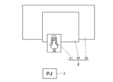
図1は本実施形態に係る投影装置1を備える投影システム100の概略構成を模式的に示す側面図である。図2は投影システム100の概略構成を投影装置1側から見た模式図である。
図1及び図2に示すように投影システム100には、画像情報を時系列で投影するためのシナリオデータに基づいて画像を投影する投影装置1と、投影装置1に対してシナリオデータを出力するパソコン(パーソナルコンピュータ)2と、複数の投影面31,32,33を有するスクリーン部3とが備えられている。複数の投影面31,32,33のうち、第一投影面31は投影装置1から距離d1の位置に配置され、第二投影面32は距離d2の位置に配置され、第三投影面33は距離d3の位置に配置されている。
FIG. 1 is a side view schematically showing a schematic configuration of a
As shown in FIGS. 1 and 2, the
図3は投影装置1及びパソコン2の制御構成を示すブロック図である。図3に示すように、パソコン2には、CPU21、RAM22、VRAM23、入力手段24、通信手段25及び記録手段26が備えられており、これらが電気的に接続されている。
通信手段25には、LANケーブルやシリアル通信ケーブルなどの通信ケーブル27が通信ポート28を介して接続されている。
VRAM23には、HDMIケーブルや、アナログビデオ信号ケーブル、DVIケーブルなどの映像ケーブル29が映像出力端子23aを介して接続されている。
通信ケーブル27及び映像ケーブル29は、投影装置1に接続されている。
記録手段26には、投影装置1に対して種々の制御を行うための描画アプリケーション26aと、描画アプリケーション26aの実行に際して読み出される複数のシナリオデータ26bが記録されている。
入力手段24は、例えばマウスやキーボードなどである。
FIG. 3 is a block diagram showing a control configuration of the
A
A
The
The
The input means 24 is, for example, a mouse or a keyboard.
CPU21は、入力手段24の操作によって描画アプリケーション26aが選択されると、当該描画アプリケーション26aのプログラムをRAM22に展開して、描画アプリケーション26aを実行する。描画アプリケーション26aの機能としては、シナリオデータ26bの作成や、シナリオデータ26bを投影装置1に転送し、シナリオデータ26bに基づく画像を投影装置1から投影させることなどである。
When the
投影装置1には、CPU11、RAM12、映像入力端子13、通信手段14、入力手段15、光源制御手段16、描画制御手段17、投影サイズ制御手段18及びフォーカス制御手段19が備えられており、これらが電気的に接続されている。
通信手段14には、通信ケーブル27が接続されており、パソコン2側から出力された制御信号が入力されるようになっている。
映像入力端子13には、映像ケーブル29が接続されており、パソコン2側から出力された映像信号が入力されるようになっている。
The
A
A
光源制御手段16には投影光の光源16aが接続されている。光源制御手段16は、CPU11からの制御信号に基づいて光源16aを制御する。
描画制御手段17には、DMD(Digital Micromirror Device)素子やLCD(Liquid Crystal Display)素子などの映像信号を画像に変換する描画素子17aが接続されている。描画制御手段17は、映像入力端子13から映像信号として入力されたシナリオデータ26b及びCPU11からの制御信号に基づいて描画素子17aを制御する。
投影サイズ制御手段18及びフォーカス制御手段19には、光源16aから照射され、描画素子17aを透過/反射した投影光を合焦する投影レンズ18aが接続されている。投影レンズ18aには、倍率調整用レンズや焦点調整用レンズが含まれている。投影サイズ制御手段18は、シナリオデータ26b及びCPU11からの制御信号に基づいて倍率調整用レンズを制御し、投影した画像の倍率を調整する。フォーカス制御手段19は、シナリオデータ26b及びCPU11からの制御信号に基づいて焦点調整用レンズを制御し、投影した画像のフォーカスを調整する。
これら光源制御手段16、描画制御手段17、投影サイズ制御手段18、フォーカス制御手段19、光源16a、描画素子17a及び投影レンズ18aが本発明に係る投影手段である。
入力手段15は、投影装置1の本体に搭載された操作スイッチや、図示しないリモコンの操作スイッチ等である。入力手段15を操作することで、投影倍率やフォーカスの調整を行うことが可能となっている。
なお、本実施形態ではパソコン2の通信手段25と投影装置1の通信手段14との通信が有線で行われる場合を例示しして説明したが、無線による通信を用いることも可能である。
A
The
The projection size control means 18 and the focus control means 19 are connected to a
The light source control means 16, the drawing control means 17, the projection size control means 18, the focus control means 19, the
The
In the present embodiment, the case where communication between the
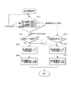
図4は、シナリオデータ26bの作成手順を示すフローチャートである。
パソコン2では、描画アプリケーション24aを実行することにより、シナリオデータ26bの作成が可能となっている。
図4のステップS1に示すように、先ずシナリオデータ26bの企画テーマを決定する。
ステップS2では、企画テーマに沿うように投影先のレイアウト案を決定する。具体的なレイアウト案としては、図1及び図2に示すスクリーン部3の各投影面31,32,33の設置個数や、形状、大きさ、設置座標等である。
FIG. 4 is a flowchart showing a procedure for creating the
The
As shown in step S1 of FIG. 4, the plan theme of the
In step S2, the layout plan of the projection destination is determined so as to follow the plan theme. Specific layout proposals include the number of installed projection surfaces 31, 32, and 33, the shape, size, installation coordinates, and the like of the
ステップS3では、投影装置1の配置や投影方法を決定する。この段階で、投影先のレイアウト案に適合する投影面積や明るさなどを有する種類の投影装置1が選定される。
ステップS4では、投影先のレイアウト案に基づき、描画素子17aにおける全体描画領域の背景レイアウトを決定する。
In step S3, the arrangement of the
In step S4, the background layout of the entire drawing area in the
図5は、描画素子17aの全体描画領域17bと、スクリーン部3の各投影面31,32,33との関係を示す説明図である。描画素子17aの全体描画領域17bには、各投影面31,32,33に対応するように描画領域31b,32b,33bが設定されている。具体的には、第一描画領域31bから投影された映像は第一投影面31と重なるように設定されている。同様に、第二描画領域32bから投影された映像は第二投影面32と重なるように設定されている。第三描画領域33bから投影された映像は第二投影面33と重なるように設定されている。
各投影面31,32,33に基づく各描画領域31b,32b,33bの設定は、実際のスクリーン部3と投影装置1との位置関係から割り出しても良いし、実寸大のダミーモデルや、ミニチュアサイズのダミーモデルでのテストによって割り出してもよい。また、CGなどによるシミュレーションから行ってもよい。
FIG. 5 is an explanatory diagram showing the relationship between the
The setting of each
そして、各描画領域31b,32b,33bの設定が完了すると、各描画領域31b,32b,33bの背景レイアウトを設定する。背景レイアウトとは、映像オブジェクトが表示される1つの描画領域31b,32b,33bが決定されると、当該描画領域31b,32b,33b以外の全体描画領域17bの部分を背景として設定するレイアウトのことである。背景として設定された部分は、例えば光を投影しないように黒色として表現される。なお、映像オブジェクトの表示を見えにくくしない範囲であれば、背景として設定された部分に単一色や、画像を投影してもよい。
When the setting of each
図4のステップS5では、企画テーマに沿うような映像オブジェクトやその動きを決定する。
ステップS6では、映像オブジェクトを表示する各フレームにフォーカス制御データ(フォーカス情報)を付与する。フォーカス制御データは、直前のフレームのフォーカス制御データとの差分である。
ステップS7では、映像オブジェクトの画像情報や、フォーカス制御データを1フレーム毎に一体化してシナリオデータ26bを記録手段26に記録させる。
図6はシナリオデータ26bのデータフォーマットを示す説明図である。図6に示すようにシナリオデータ26bは、1フレームからNフレームまでの多数のフレームデータ26cを有している。1つのフレームデータ26cは、映像オブジェクトをなす1フレーム分の画像情報26dと、当該画像情報26dの表示タイミングや映像オブジェクトの投影個数などを示すヘッダ情報26eと、画像情報26dの投影対象に対するフォーカス制御データ26fとが一体化されている。
In step S5 in FIG. 4, a video object and its movement that match the plan theme are determined.
In step S6, focus control data (focus information) is assigned to each frame displaying the video object. The focus control data is a difference from the focus control data of the immediately preceding frame.
In step S7, the image information of the video object and the focus control data are integrated for each frame, and the
FIG. 6 is an explanatory diagram showing the data format of the
次に、投影装置1の焦点調整手順について説明する。図7は投影装置1の焦点調整手順を示すフローチャートである。
投影装置1の焦点調整には、入力手段15の操作キーが操作されることで焦点調整を行う直接的な焦点調整処理と、外部機器から入力された制御信号に基づいて焦点調整を行う間接的な焦点調整処理とがある。以下の説明では、焦点調整用の操作キーとして、焦点位置を手前に一段階近づける操作キーを近接キーとし、焦点位置を遠方に一段階遠ざける操作キーを遠隔キーとする。また、焦点調整用の制御信号として、焦点位置を手前に一段階近づける制御信号を近接信号とし、焦点位置を遠方に一段階遠ざける制御信号を遠隔信号とする。
Next, the focus adjustment procedure of the
For the focus adjustment of the
図7に示すように、ステップS11では、投影装置1のCPU11は、焦点調整に関する操作キーが操作されたか、焦点調整に関する制御信号が入力されたかを判断し、前記操作キーが操作された場合はステップS12に移行し、前記制御信号が入力された場合にはステップS13に移行し、これらの操作や入力が行われていない場合はそのままの状態で待機する。
As shown in FIG. 7, in step S11, the
ステップS12では、投影装置1のCPU11は、操作された操作キーが近接キーであるか否かを判断し、近接キーである場合にはステップS14に移行し、近接キーでない場合、つまり遠隔キーの場合にはステップS15に移行する。
In step S12, the
ステップS13では、投影装置1のCPU11は、入力された制御信号が近接信号であるか否かを判断し、近接信号である場合にはステップS14に移行し、近接信号でない場合、つまり遠隔信号の場合にはステップS15に移行する。
ステップS14では、投影装置1のCPU11は、焦点調整用レンズの設定値を現在の値から1を差し引き、ステップS16に移行する。
ステップS15では、投影装置1のCPU11は、焦点調整用レンズの設定値を現在の値に1を加え、ステップS17に移行する。
In step S13, the
In step S14, the
In step S15, the
ステップS16では、投影装置1のCPU11は、焦点調整用レンズの設定値に基づいてフォーカス制御手段19を制御することで、焦点調整用レンズを一段階手前に移動させる。
ステップS17では、投影装置1のCPU11は、焦点調整用レンズの設定値に基づいてフォーカス制御手段19を制御することで、焦点調整用レンズを一段階奥に移動させる。
In step S <b> 16, the
In step S17, the
次に、シナリオデータ26bの再生手順について説明する。
図8はシナリオデータ26bの再生手順を示すフローチャートである。
投影装置1のCPU11は、パソコン2からシナリオデータ26bが入力されると、シナリオデータ再生処理を実行する。
Next, a procedure for reproducing the
FIG. 8 is a flowchart showing a procedure for reproducing the
When
ステップS21では、投影装置1のCPU11はnを0にリセットし、ステップS22に移行する。
ステップS22では、投影装置1のCPU11はnに1を加え、ステップS23に移行する。
ステップS23では、投影装置1のCPU11は、入力されたシナリオデータ26bからn番目のフレームデータ26cを読み出す。
In step S21, the
In step S22, the
In step S23, the
ステップS24では、投影装置1のCPU11は、n番目のフレームデータ26cから画像情報26dをデコードし、ステップS25に移行する。
ステップS25では、投影装置1のCPU11は、n番目のフレームデータ26cからフォーカス制御データ26fをデコードし、ステップS27に移行する。
これらステップS24及びステップS25が本発明に係る解釈工程であり、投影装置1のCPU11が本発明に係る解釈手段である。
In step S24, the
In step S25, the
These steps S24 and S25 are interpretation processes according to the present invention, and the
ステップS26では、投影装置1のCPU11は、フォーカス制御データ26fから焦点調整用レンズの移動量を決定する。具体的に説明すると、フォーカス制御データ26fは、例えば2バイトデータとしてフレームデータ26cに含まれている。2バイトデータのうち、上位の1バイトが「0x00」の場合は現在の位置を基準とした焦点調整用レンズの移動量及び移動方向を示している。この場合、下位の1バイトのうち、上位の4ビットが奥側への移動量を示し、下位の4ビットが手前側への移動量を示している。例えば、移動をしない場合には「0x0000」、奥側へ二段階移動させる場合は「0x0020」、手前側に三段階移動させる場合は「0x0003」となる。このようなデータ形式のために、フォーカス制御データ26fは直前のフレームの差分として記録されている。
In step S26, the
他方、2バイトデータのうち、上位の1バイトが「0xff」の場合は初期設定のフォーカス位置に焦点調整用レンズを移動させる旨を示している。この場合、下位の1バイトの値は無視する。
なお、フォーカス制御データ26fの形式はこれに限定されるものではなく、周知のデータ形式を好適に用いることが可能である。
On the other hand, when the upper one byte of the 2-byte data is “0xff”, this indicates that the focus adjustment lens is moved to the initial focus position. In this case, the value of the lower 1 byte is ignored.
The format of the
ステップS27では、投影装置1のCPU11は、フォーカス制御データ26fが「0x0000」であると焦点調整用レンズの移動なしと判断してステップS30に移行し、「0x0000」以外であると焦点調整用レンズの移動がありと判断してステップS28に移行する。
In step S27, if the
ステップS28では、投影装置1のCPU11は、フォーカス制御データ26fにある移動量から遠隔信号又は近接信号の入力回数を決定し、ステップS29に移行する。ここで上位の1バイトが「0x00」の場合は、下位の4バイトで示される値、つまり直前のフレームの差分から遠隔信号又は近接信号の入力回数が決まる。例えば「0x0020」であると奥側に二段階移動させる旨が示されているので遠隔信号の入力回数が2回ということになる。また、「0x0003」であると手前側に三段階移動させる旨が示されているので近接信号の入力回数が3回ということになる。
なお、「0xff00」の場合には、焦点調整用レンズの現在位置と初期位置との差分から移動量及び移動方向を割り出し、遠隔信号又は近接信号の入力回数を決定する。
In step S28, the
In the case of “0xff00”, the moving amount and moving direction are determined from the difference between the current position and the initial position of the focus adjustment lens, and the number of inputs of the remote signal or the proximity signal is determined.
ステップS29では、投影装置1のCPU11は、決定された入力回数分だけ焦点調整処理を実行し、ステップS30に移行する。このステップS29が本発明に係る反映工程であり、CPU11が本発明の制御手段となる。
ステップS30では、投影装置1のCPU11は、ステップS24でデコードした画像情報26dに基づいて描画制御手段17を制御することで、画像情報26dに基づく画像を描画素子17aに表示させる。これによりフレームデータ26cが更新され、スクリーン部3に画像が表示される。つまり、ステップS30が本発明に係る投影工程である。更新後、ステップS31に移行する。
ステップS31では、投影装置1のCPU11は、次のフレームデータ26cの表示タイミングまで待機し、ステップS32に移行する。
In step S29, the
In step S30, the
In step S31, the
ステップS32では、投影装置1のCPU11は、n=Nであるか否かを判断し、n<Nである場合にはステップS22に移行して、n=Nである場合には1シナリオデータ26bの再生が終わったこととなり、再生処理を終了する。
In step S32, the
次に、投影対象の切替について具体例を挙げて説明する。
投影対象として第一投影面31が設定されている場合、画像情報26dは第一描画領域31b内に収まる映像オブジェクトが設定されている。図9は、第一描画領域31b内に収まる映像オブジェクトとして「女の子」が設定されていて、当該第一描画領域31bに描画された画像が第一投影面31に投影された状態を示している。
投影対象として第二投影面32が設定されている場合、画像情報26dは第二描画領域32b内に収まる映像オブジェクトが設定されている。図10は、第二描画領域32b内に収まる映像オブジェクトとして「男の子」が設定されていて、当該第二描画領域32bに描画された画像が第二投影面32に投影された状態を示している。
投影対象として第三投影面33が設定されている場合、画像情報26dは第三描画領域33b内に収まる映像オブジェクトが設定されている。図11は、第三描画領域33b内に収まる映像オブジェクトとして「青年男子」が設定されていて、当該第三描画領域33bに描画された画像が第三投影面33に投影された状態を示している。
なお、いずれの場合においても、スクリーン部3における投影対象以外の部分は、前述した背景レイアウトに対応していて、光を投影しないよう黒色として表現されている。
Next, switching of the projection target will be described with a specific example.
When the
When the
When the
In any case, the portion other than the projection target in the
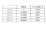
図12はシナリオデータ26bの一例として1フレームから5フレームまでの投影対象及び各フォーカス制御データ26fを示す図である。図12の例であると、先ず1フレーム目では投影対象が設定されていないためフォーカス制御データ26fが「0xff00」に設定され、これにより焦点調整用レンズを初期位置に移動させることとなる。なお、本実施形態では焦点調整用レンズの初期位置は第二投影面32に焦点が合う位置である。
2フレーム目では投影対象が第二投影面32に設定されているため、フォーカス制御データ26fが「0x0000」に設定されている。つまり、焦点調整用レンズの移動は行われない。そして、このときの画像情報26dは図10に示すように第二描画領域32b内に収まる映像オブジェクトが設定されているので、第二投影面32に画像が投影されることになる。
FIG. 12 is a diagram showing projection objects from 1 frame to 5 frames and each focus
In the second frame, since the projection target is set to the
3フレーム目では投影対象が第一投影面31に設定されているため、フォーカス制御データ26fが「0x0001」に設定されている。つまり、2フレーム目から一段階だけ手前に焦点投影用レンズを移動させる。そして、このときの画像情報26dは図9に示すように第一描画領域31b内に収まる映像オブジェクトが設定されているので、第一投影面31に画像が投影されることになる。
4フレーム目では投影対象が第二投影面32に設定されているため、フォーカス制御データ26fが「0x0010」に設定されている。つまり、3フレーム目から一段階だけ奥側に焦点投影用レンズを移動させる。そして、このときの画像情報26dは図10に示すように第二描画領域32b内に収まる映像オブジェクトが設定されているので、第二投影面32に画像が投影されることになる。
5フレーム目では投影対象が第三投影面33に設定されているため、フォーカス制御データ26fが「0x0010」に設定されている。つまり、4フレーム目から一段階だけ奥側に焦点投影用レンズを移動させる。そして、このときの画像情報26dは図11に示すように第三描画領域33b内に収まる映像オブジェクトが設定されているので、第三投影面33に画像が投影されることになる。
In the third frame, since the projection target is set to the
In the fourth frame, since the projection target is set to the
In the fifth frame, since the projection target is set to the
なお、本実施形態では、焦点調整用レンズが一段階ずつ移動することで、各投影面31,32,33に焦点が合う場合を例示して説明したが、一段階分の移動量をより小さくして、複数段階分の移動量で焦点を合わすようにしてもよい。この場合、各投影面31,32,33を等間隔に配置しなくとも焦点を合わすことが可能になる。
また、本実施形態では、映像オブジェクトが1つの投影面31,32,33に収まるようになっているが、複数の投影面31,32,33にわたって映像オブジェクトを表示させるとも可能である。この場合、複数の投影面31,32,33のうち、優先される投影面31,32,33を投影対象として事前に決定し、その投影対象となった投影面31,32,33に焦点を合わせてもよい。また、複数の投影面31,32,33の中間位置か、或いは現在の位置で焦点を合わせてもよい。極端な焦点ズレは防止することが可能である。
In the present embodiment, the case where each of the projection surfaces 31, 32, 33 is focused by moving the focus adjustment lens one step at a time has been described as an example, but the amount of movement for one step is smaller. Then, the focus may be adjusted by a movement amount for a plurality of stages. In this case, the projection surfaces 31, 32, and 33 can be focused without being arranged at equal intervals.
In the present embodiment, the video object fits on one
以上のように、本実施形態によれば、シナリオデータ26bには、1フレーム毎に、画像情報26dと、当該画像情報26dが投影される際のフォーカス制御データ(フォーカス情報)26fとが一体化されているので、フレームデータ26cをデコードすれば画像情報26d及びフォーカス制御データを個別に抽出することができる。したがって、一台の投影装置1であっても、フレーム毎の投影対象(投影面31,32,33)の変動に応じて柔軟に合焦することができ、フォーカスに関する演出を容易に行うことが可能となる。
As described above, according to the present embodiment, the
また、フォーカス制御データ26fが直前のフレームの差分として設定されているので、焦点調整用レンズの移動の度に現状の値との差分を計算する必要もなくなり、迅速に焦点調整用レンズの移動を実行することができる。
しかし、本発明は、フォーカス制御データ26fが差分値で表現されていないものを除外するものではないことは言うまでもない。
Further, since the
However, it goes without saying that the present invention does not exclude the case where the
なお、本発明は上記実施形態に限らず適宜変更可能である。以下の説明において上記実施形態と同一の部分においては同一の符号を付してその説明を省略する。 Note that the present invention is not limited to the above embodiment, and can be modified as appropriate. In the following description, the same parts as those in the above embodiment are denoted by the same reference numerals, and the description thereof is omitted.
上記実施形態では、投影装置1の投影方向に対して直交するように投影面31,32,33が配置された場合を例示したが、以下の変形例では投影装置1の投影方向に対して斜めとなるように投影面31,32,33が配置された場合を例示して説明する。
図13は、投影装置1と投影面31,32,33との配置を異ならせた一例を示す説明図である。図13に示すように、室内200の1つの壁201に対して平行となるように投影面31,32,33が配置されている。第一投影面31が最も壁201から離れていて、第三投影面33が最も壁201に近く、第二投影面32が第一投影面31と第二投影面33との間に配置されている。投影装置1はいずれの投影面31,32,33よりも手前の右側に配置されている。各投影面31,32,33中には、投影領域31a,32a,33aが設定されていて、この内側に映像オブジェクトが投影されることになる。
In the above-described embodiment, the case where the projection surfaces 31, 32, and 33 are arranged so as to be orthogonal to the projection direction of the
FIG. 13 is an explanatory diagram illustrating an example in which the arrangement of the
図14は描画素子17aの全体描画領域17bと、各投影面31,32,33の投影領域31a,32a,33aとの関係を示す説明図である。描画素子17aの全体描画領域17bには、各投影領域31a,32a,33aに対応するように描画領域31c,32c,33cが設定されている。ここで、投影後に各投影領域31a,32a,33aに一致するように各投影領域31a,32a,33aは台形状に設定されている。これは投影装置1の投影方向に対して斜めに投影面31,32,33が配置されていることを考慮したためである。なお、図13においては全体描画領域17bの投影領域は、波線L1で囲まれた領域である。
FIG. 14 is an explanatory diagram showing the relationship between the
次に、投影対象の切替について具体例を挙げて説明する。
投影対象として第一投影面31が設定されている場合、画像情報26dは第一描画領域31c内に収まる映像オブジェクトが設定されている。図15は、第一描画領域31c内に収まる映像オブジェクトとして「女の子」が設定された状態を示している。当該第一描画領域31cに描画された画像が第一投影面31の投影領域31aに投影されると「女の子」が表示されることになる。
投影対象として第二投影面32が設定されている場合、画像情報26dは第二描画領域32c内に収まる映像オブジェクトが設定されている。図16は、第二描画領域32c内に収まる映像オブジェクトとして「男の子」が設定された状態を示している。当該第二描画領域32cに描画された画像が第二投影面32の投影領域32aに投影されると「男の子」が表示されることになる。
投影対象として第三投影面33が設定されている場合、画像情報26dは第三描画領域33c内に収まる映像オブジェクトが設定されている。図17は、第三描画領域33c内に収まる映像オブジェクトとして「成年男子」が設定された状態を示している。当該第三描画領域33cに描画された画像が第三投影面33の投影領域33aに投影されると「成年男子」が表示されることになる。
Next, switching of the projection target will be described with a specific example.
When the
When the
When the
図18はシナリオデータ26bの一例として1フレームから4フレームまでの投影対象及び各フォーカス制御データ26fを示す図である。図18の例であると、先ず1フレーム目では投影対象が設定されていないためフォーカス制御データ26fが「0xff00」に設定され、これにより焦点調整用レンズを初期位置に移動させることとなる。なお、本実施形態では焦点調整用レンズの初期位置は第二投影面32に焦点が合う位置である。
2フレーム目では投影対象が第一投影面31に設定されているため、フォーカス制御データ26fが「0x0001」に設定されている。つまり、1フレーム目から一段階だけ手前に挑戦投影用レンズを移動させる。そして、このときの画像情報26dは図15に示すように第一描画領域31b内に収まる映像オブジェクトが設定されているので、第一投影面31の投影領域31aに画像が投影されることになる。
FIG. 18 is a diagram showing projection objects from the first frame to the fourth frame and each focus
In the second frame, since the projection target is set to the
3フレーム目では投影対象が第二投影面32に設定されているため、フォーカス制御データ26fが「0x0010」に設定されている。つまり、2フレーム目から一段階だけ奥側に焦点投影用レンズを移動させる。そして、このときの画像情報26dは図16に示すように第二描画領域32b内に収まる映像オブジェクトが設定されているので、第二投影面32の投影領域32aに画像が投影されることになる。
4フレーム目では投影対象が第三投影面33に設定されているため、フォーカス制御データ26fが「0x0010」に設定されている。つまり、3フレーム目から一段階だけ奥側に焦点投影用レンズを移動させる。そして、このときの画像情報26dは図17に示すように第三描画領域33b内に収まる映像オブジェクトが設定されているので、第三投影面33の投影領域33aに画像が投影されることになる。
In the third frame, since the projection target is set to the
In the fourth frame, since the projection target is set to the
また、上記実施形態では、フォーカス制御データ26fとして焦点調整用レンズの移動量及び移動方向が段階的に設けられている場合を例示して説明したが、投影装置1と投影対象(投影面31,32,33)との距離をフォーカス制御データ26fとして用いることも可能である。この場合、投影装置1と投影対象との距離に基づいて、画像情報26dが各投影面31,32,33に合焦して投影されるように焦点調整用レンズの移動量及び移動方向をCPU11が算出することになる。したがって、段階的に設定されたフォーカス制御データ26fよりもリニアな距離変動に正確に対応することができる。
In the above embodiment, the case where the movement amount and the movement direction of the focus adjustment lens are provided in stages as the
また、上記実施形態では、画像情報26dが投影対象に対して合焦して投影されるためのフォーカス制御データ26fを例示して説明したが、投影対象に対して画像情報26dを合焦させないぼかし情報をフォーカス制御データ26fが含んでいてもよい。この場合、投影対象に画像情報26dを意図的にぼかして表示させるといったことが可能となるため、演出効果をより高めることができる。
ぼかし情報とは、画像情報26dを投影対象に合焦させない範囲での焦点調整用レンズの移動量及び移動方向である。
In the above-described embodiment, the
The blur information is the moving amount and moving direction of the focus adjustment lens within a range where the
また、上記実施形態では、シナリオデータ26bの1フレーム毎に画像情報26dとフォーカス制御データ26fとが一体化されている場合を例示した。このフォーカス制御データ26fは、画像情報26dが投影される際の投影条件の一例である。すわなち、フォーカス制御データ26f以外の投影条件も画像情報24cとともに1フレーム毎に一体化することも可能である。
これにより、シナリオデータ26bのフレーム毎に投影条件が変動する場合においても、一台の投影装置1で柔軟に投影条件の変動に対応することができる。
In the above embodiment, the case where the
Thus, even when the projection condition varies for each frame of the
なお、フォーカス制御データ26f以外の投影条件としては、例えば画像情報26dの投影対象に対するズーム情報と、画像情報26dの投影対象に対する明暗情報(ブライト情報)、画像情報26dの投影対象の位置及びサイズの少なくとも一方を有する投影面情報などが挙げられる。なお、投影条件は1種類のみが画像情報26dと一体化されていてもよく、複数種類がまとめて画像情報26dと一体化されていてもよい。
The projection conditions other than the
投影条件として画像情報26dの投影対象に対するズーム情報が用いられている場合には、フレームデータ26cをデコードすれば画像情報26d及びズーム情報を個別に抽出することができる。したがって、一台の投影装置1であっても、フレーム毎の拡大縮小を柔軟に行うことができ、拡大縮小に関する演出を容易に行うことが可能となる。
When the zoom information for the projection target of the
投影条件として画像情報26dの明暗情報が用いられている場合には、フレームデータ26cをデコードすれば画像情報26d及び明暗情報を個別に抽出することができる。したがって、一台の投影装置1であっても、フレーム毎の明るさ調整を柔軟に行うことができ、投影画像の明るさに関する演出を画像情報26dとは独立して行うことが可能となる。
When the light / dark information of the
投影条件として投影面情報が用いられている場合には、上述したように描画素子17aの各描画領域31b,32b,33bのそれぞれに映像オブジェクトの詳細を事前に設定しなくともよくなる。具体的には、投影面情報としての投影対象の位置としては、投影装置1から投影対象(投影面31,32,33)までの距離や、各投影面31,32,33の投影可能領域の中心の座標位置、投影装置1の投影方向に対して各投影面31,32,33が傾いている場合にはその角度などが挙げられる。投影面情報としての投影対象のサイズとしては、各投影面31,32,33の投影可能領域の大きさが挙げられる。
投影装置1のCPU11は、投影面情報に基づいて映像オブジェクトの画像情報26bを投影前に適切に加工する。
例えば、画像情報26dとして「女の子」の映像オブジェクトのみが設定されていて、投影面情報として第一投影面31の位置とサイズとが設定されている場合には、図9に示すように第一投影面31に対して「女の子」の映像オブジェクトが投影されるように、画像情報26bが適切に加工されている。同様に、画像情報26dとして「女の子」の映像オブジェクトのみが設定されていて、投影面情報として第二投影面32の位置とサイズとが設定されている場合には、図19に示すように第二投影面32に対して「女の子」の映像オブジェクトが投影されるように、画像情報26bが適切に加工されている。そして、画像情報26dとして「女の子」の映像オブジェクトのみが設定されていて、投影面情報として第三投影面33の位置とサイズとが設定されている場合には、図20に示すように第三投影面33に対して「女の子」の映像オブジェクトが投影されるように、画像情報26bが適切に加工されている。
いずれの場合においても、投影対象のサイズに収まるように「女の子」の画像情報26bが投影前に加工されて映像オブジェクトの大きさが変更され、その周辺は黒データとして加工される。
このようにすると、映像オブジェクト自体を共通にして、投影に際しては、投影条件を反映して投影するようにでき、シナリオデータの作成の自由度、汎用性を高めることができる。
When the projection plane information is used as the projection condition, it is not necessary to set the details of the video object in advance in each of the
The
For example, when only the video object “girl” is set as the
In any case, the
In this way, the video object itself can be shared, and the projection can be performed while reflecting the projection conditions, and the degree of freedom for creating scenario data and versatility can be improved.
なお、投影面は、上述したスクリーン部3や、壁面など以外にも天井や床、車両、ビルや橋などの構造物の外壁面などでもよい。
また、投影面はフラットな平面以外にも、映像オブジェクトの歪みが補正可能ならば球面であっても多角錐の側面、それ以外の曲面であってもよい。
Note that the projection surface may be an outer wall surface of a structure such as a ceiling, a floor, a vehicle, a building, or a bridge in addition to the
In addition to a flat plane, the projection plane may be a spherical surface, a side surface of a polygonal pyramid, or a curved surface other than that if the distortion of the video object can be corrected.
本発明のいくつかの実施形態を説明したが、本発明の範囲は、上述の実施の形態に限定するものではなく、特許請求の範囲に記載された発明の範囲とその均等の範囲を含む。
以下に、この出願の願書に最初に添付した特許請求の範囲に記載した発明を付記する。付記に記載した請求項の項番は、この出願の願書に最初に添付した特許請求の範囲の通りである。
Although several embodiments of the present invention have been described, the scope of the present invention is not limited to the above-described embodiments, but includes the scope of the invention described in the claims and equivalents thereof.
The invention described in the scope of claims attached to the application of this application will be added below. The item numbers of the claims described in the appendix are as set forth in the claims attached to the application of this application.
〔付記〕
<請求項1>
投影装置によって画像情報を時系列で投影するためのシナリオデータであって、
1フレーム毎に、前記画像情報と、当該画像情報が投影される際の投影条件とが一体化されていることを特徴とするシナリオデータ。
<請求項2>
請求項1記載のシナリオデータにおいて、
前記投影条件は、前記画像情報の投影対象に対するフォーカス情報を含んでいることを特徴とするシナリオデータ。
<請求項3>
請求項2記載のシナリオデータにおいて、
前記投影条件は、前記投影装置から前記画像情報の投影対象までの距離を前記フォーカス情報として有していることを特徴とするシナリオデータ。
<請求項4>
請求項1〜3のいずれか一項に記載のシナリオデータにおいて、
前記投影条件は、前記画像情報の投影対象の位置及びサイズの少なくとも一方を有する投影面情報を含んでいることを特徴とするシナリオデータ。
<請求項5>
請求項1〜4のいずれか一項に記載のシナリオデータにおいて、
前記投影条件は、直前のフレームの前記投影条件との差分として設定されていることを特徴とするシナリオデータ。
<請求項6>
請求項1〜5のいずれか一項に記載のシナリオデータにおいて、
前記投影条件は、前記画像情報の投影対象に対するズーム情報を含んでいることを特徴とするシナリオデータ。
<請求項7>
請求項1〜6のいずれか一項に記載のシナリオデータにおいて、
前記投影条件は、前記画像情報の投影対象に対する明暗情報を含んでいることを特徴とするシナリオデータ。
<請求項8>
画像情報を時系列で投影するためのシナリオデータに基づいて画像を投影する投影装置であって、
前記画像情報を投影対象に投影する投影手段と、
1フレーム毎に、前記画像情報と、当該画像情報が投影される際の投影条件とが一体化された前記シナリオデータをデコードする解釈手段と、
前記解釈手段で解釈された各フレームの画像情報を投影する際には当該画像情報に対応する投影条件が反映されるように前記投影手段を制御する制御手段とを備えることを特徴とする投影装置。
<請求項9>
請求項8記載の投影装置において、
前記投影条件は、前記画像情報の投影対象の位置及びサイズの少なくとも一方を有する投影面情報を含み、
前記解釈手段は、前記シナリオデータに含まれる前記投影面情報を解釈し、
前記制御手段は、前記解釈手段で解釈された前記投影面情報に対応するように、前記画像情報を投影前に加工することを特徴とする投影装置。
<請求項10>
画像情報を時系列で投影するためのシナリオデータに基づいて画像を投影する投影方法であって、
前記画像情報を投影対象に投影する投影工程と、
1フレーム毎に、前記画像情報と、当該画像情報が投影される際の投影条件とが一体化された前記シナリオデータをデコードする解釈工程と、
前記解釈工程で解釈された各フレームの画像情報を投影する際に、当該画像情報に対応する投影条件を前記投影工程で反映させる反映工程とを備えることを特徴とする投影方法。
<請求項11>
請求項10記載の投影方法において、
前記投影条件は、前記画像情報の投影対象に対するフォーカス情報を含み、
前記フォーカス情報は前記画像情報を投影対象に合焦させないぼかし情報を含んでいることを特徴とする投影方法。
[Appendix]
<Claim 1>
Scenario data for projecting image information in time series by a projection device,
Scenario data, wherein the image information and a projection condition for projecting the image information are integrated for each frame.
<Claim 2>
In the scenario data of
The scenario data, wherein the projection condition includes focus information for a projection target of the image information.
<Claim 3>
In the scenario data according to
Scenario data, wherein the projection condition includes a distance from the projection device to a projection target of the image information as the focus information.
<Claim 4>
In the scenario data according to any one of
The scenario data, wherein the projection condition includes projection plane information having at least one of a position and a size of a projection target of the image information.
<Claim 5>
In the scenario data according to any one of
Scenario data, wherein the projection condition is set as a difference from the projection condition of the immediately preceding frame.
<Claim 6>
In the scenario data according to any one of
The scenario data, wherein the projection condition includes zoom information for a projection target of the image information.
<Claim 7>
In the scenario data according to any one of
Scenario data, wherein the projection condition includes light / dark information for a projection target of the image information.
<Claim 8>
A projection device that projects an image based on scenario data for projecting image information in time series,
Projecting means for projecting the image information onto a projection target;
Interpretation means for decoding the scenario data in which the image information and the projection conditions for projecting the image information are integrated for each frame;
And a control unit that controls the projection unit such that a projection condition corresponding to the image information is reflected when projecting the image information of each frame interpreted by the interpretation unit. .
<Claim 9>
The projection apparatus according to claim 8, wherein
The projection condition includes projection plane information having at least one of a position and a size of a projection target of the image information,
The interpreting means interprets the projection plane information included in the scenario data;
The projection apparatus, wherein the control means processes the image information before projection so as to correspond to the projection plane information interpreted by the interpretation means.
<Claim 10>
A projection method for projecting an image based on scenario data for projecting image information in time series,
Projecting the image information onto a projection target;
An interpretation step of decoding the scenario data in which the image information and a projection condition when the image information is projected are integrated for each frame;
A projecting method, comprising: reflecting a projection condition corresponding to the image information in the projecting step when projecting the image information of each frame interpreted in the interpreting step.
<Claim 11>
The projection method according to
The projection condition includes focus information for a projection target of the image information,
The projection method, wherein the focus information includes blur information that does not focus the image information on a projection target.
1 投影装置
2 パソコン
3 スクリーン部
11 CPU(解釈手段、制御手段)
16 光源制御手段(投影手段)
16a 光源(投影手段)
17 描画制御手段(投影手段)
17a 描画素子(投影手段)
17b 全体描画領域
18 投影サイズ制御手段(投影手段)
18a 投影レンズ(投影手段)
19 フォーカス制御手段(投影手段)
26b シナリオデータ
26c フレームデータ
26d 画像情報
26e ヘッダ情報
26f フォーカス制御データ
31 第一投影面(投影対象)
32 第二投影面(投影対象)
33 第三投影面(投影対象)
100 投影システム
DESCRIPTION OF
16 Light source control means (projection means)
16a Light source (projection means)
17 Drawing control means (projection means)
17a Drawing element (projection means)
17b
18a Projection lens (projection means)
19 Focus control means (projection means)
32 Second projection plane (projection target)
33 Third projection plane (projection target)
100 Projection system
Claims (11)
1フレーム毎に、前記画像情報と、当該画像情報が投影される際の投影条件とが一体化されていることを特徴とするシナリオデータ。 Scenario data for projecting image information in time series by a projection device,
Scenario data, wherein the image information and a projection condition for projecting the image information are integrated for each frame.
前記投影条件は、前記画像情報の投影対象に対するフォーカス情報を含んでいることを特徴とするシナリオデータ。 In the scenario data of claim 1,
The scenario data, wherein the projection condition includes focus information for a projection target of the image information.
前記投影条件は、前記投影装置から前記画像情報の投影対象までの距離を前記フォーカス情報として有していることを特徴とするシナリオデータ。 In the scenario data according to claim 2,
Scenario data, wherein the projection condition includes a distance from the projection device to a projection target of the image information as the focus information.
前記投影条件は、前記画像情報の投影対象の位置及びサイズの少なくとも一方を有する投影面情報を含んでいることを特徴とするシナリオデータ。 In the scenario data according to any one of claims 1 to 3,
The scenario data, wherein the projection condition includes projection plane information having at least one of a position and a size of a projection target of the image information.
前記投影条件は、直前のフレームの前記投影条件との差分として設定されていることを特徴とするシナリオデータ。 In the scenario data according to any one of claims 1 to 4,
Scenario data, wherein the projection condition is set as a difference from the projection condition of the immediately preceding frame.
前記投影条件は、前記画像情報の投影対象に対するズーム情報を含んでいることを特徴とするシナリオデータ。 In the scenario data according to any one of claims 1 to 5,
The scenario data, wherein the projection condition includes zoom information for a projection target of the image information.
前記投影条件は、前記画像情報の投影対象に対する明暗情報を含んでいることを特徴とするシナリオデータ。 In the scenario data according to any one of claims 1 to 6,
Scenario data, wherein the projection condition includes light / dark information for a projection target of the image information.
前記画像情報を投影対象に投影する投影手段と、
1フレーム毎に、前記画像情報と、当該画像情報が投影される際の投影条件とが一体化された前記シナリオデータをデコードする解釈手段と、
前記解釈手段で解釈された各フレームの画像情報を投影する際には当該画像情報に対応する投影条件が反映されるように前記投影手段を制御する制御手段とを備えることを特徴とする投影装置。 A projection device that projects an image based on scenario data for projecting image information in time series,
Projecting means for projecting the image information onto a projection target;
Interpretation means for decoding the scenario data in which the image information and the projection conditions for projecting the image information are integrated for each frame;
And a control unit that controls the projection unit such that a projection condition corresponding to the image information is reflected when projecting the image information of each frame interpreted by the interpretation unit. .
前記投影条件は、前記画像情報の投影対象の位置及びサイズの少なくとも一方を有する投影面情報を含み、
前記解釈手段は、前記シナリオデータに含まれる前記投影面情報を解釈し、
前記制御手段は、前記解釈手段で解釈された前記投影面情報に対応するように、前記画像情報を投影前に加工することを特徴とする投影装置。 The projection apparatus according to claim 8, wherein
The projection condition includes projection plane information having at least one of a position and a size of a projection target of the image information,
The interpreting means interprets the projection plane information included in the scenario data;
The projection apparatus, wherein the control means processes the image information before projection so as to correspond to the projection plane information interpreted by the interpretation means.
前記画像情報を投影対象に投影する投影工程と、
1フレーム毎に、前記画像情報と、当該画像情報が投影される際の投影条件とが一体化された前記シナリオデータをデコードする解釈工程と、
前記解釈工程で解釈された各フレームの画像情報を投影する際に、当該画像情報に対応する投影条件を前記投影工程で反映させる反映工程とを備えることを特徴とする投影方法。 A projection method for projecting an image based on scenario data for projecting image information in time series,
Projecting the image information onto a projection target;
An interpretation step of decoding the scenario data in which the image information and a projection condition when the image information is projected are integrated for each frame;
A projecting method, comprising: reflecting a projection condition corresponding to the image information in the projecting step when projecting the image information of each frame interpreted in the interpreting step.
前記投影条件は、前記画像情報の投影対象に対するフォーカス情報を含み、
前記フォーカス情報は前記画像情報を投影対象に合焦させないぼかし情報を含んでいることを特徴とする投影方法。 The projection method according to claim 10.
The projection condition includes focus information for a projection target of the image information,
The projection method, wherein the focus information includes blur information that does not focus the image information on a projection target.
Priority Applications (1)
| Application Number | Priority Date | Filing Date | Title |
|---|---|---|---|
| JP2013052647A JP2014178503A (en) | 2013-03-15 | 2013-03-15 | Scenario data, projection device and projection method |
Applications Claiming Priority (1)
| Application Number | Priority Date | Filing Date | Title |
|---|---|---|---|
| JP2013052647A JP2014178503A (en) | 2013-03-15 | 2013-03-15 | Scenario data, projection device and projection method |
Publications (1)
| Publication Number | Publication Date |
|---|---|
| JP2014178503A true JP2014178503A (en) | 2014-09-25 |
Family
ID=51698503
Family Applications (1)
| Application Number | Title | Priority Date | Filing Date |
|---|---|---|---|
| JP2013052647A Pending JP2014178503A (en) | 2013-03-15 | 2013-03-15 | Scenario data, projection device and projection method |
Country Status (1)
| Country | Link |
|---|---|
| JP (1) | JP2014178503A (en) |
Cited By (2)
| Publication number | Priority date | Publication date | Assignee | Title |
|---|---|---|---|---|
| JP2016139954A (en) * | 2015-01-28 | 2016-08-04 | セイコーエプソン株式会社 | Projector and projection method |
| WO2022196426A1 (en) * | 2021-03-16 | 2022-09-22 | パナソニックIpマネジメント株式会社 | Projection system and control method for projection system |
Citations (4)
| Publication number | Priority date | Publication date | Assignee | Title |
|---|---|---|---|---|
| JP2000201361A (en) * | 1998-10-28 | 2000-07-18 | Sega Enterp Ltd | Three-dimensional image forming device |
| JP2003141522A (en) * | 2001-10-31 | 2003-05-16 | Canon Inc | Display device and information processing method |
| JP2005309968A (en) * | 2004-04-23 | 2005-11-04 | Kyosan Electric Mfg Co Ltd | Newest information display system and train operation display system using it |
| JP2012217073A (en) * | 2011-04-01 | 2012-11-08 | Seiko Epson Corp | Display system, display device and display device control method |
-
2013
- 2013-03-15 JP JP2013052647A patent/JP2014178503A/en active Pending
Patent Citations (4)
| Publication number | Priority date | Publication date | Assignee | Title |
|---|---|---|---|---|
| JP2000201361A (en) * | 1998-10-28 | 2000-07-18 | Sega Enterp Ltd | Three-dimensional image forming device |
| JP2003141522A (en) * | 2001-10-31 | 2003-05-16 | Canon Inc | Display device and information processing method |
| JP2005309968A (en) * | 2004-04-23 | 2005-11-04 | Kyosan Electric Mfg Co Ltd | Newest information display system and train operation display system using it |
| JP2012217073A (en) * | 2011-04-01 | 2012-11-08 | Seiko Epson Corp | Display system, display device and display device control method |
Cited By (2)
| Publication number | Priority date | Publication date | Assignee | Title |
|---|---|---|---|---|
| JP2016139954A (en) * | 2015-01-28 | 2016-08-04 | セイコーエプソン株式会社 | Projector and projection method |
| WO2022196426A1 (en) * | 2021-03-16 | 2022-09-22 | パナソニックIpマネジメント株式会社 | Projection system and control method for projection system |
Similar Documents
| Publication | Publication Date | Title |
|---|---|---|
| US9936179B2 (en) | Image projection apparatus and method of controlling the same, and non-transitory computer-readable storage medium | |
| JP2009273015A (en) | Projection type video display device | |
| JP2019125955A (en) | Parameter generation apparatus, control method therefor, and program | |
| JP6322993B2 (en) | Geometric correction adjustment method | |
| WO2015170507A1 (en) | Display processing device and projection type image display device | |
| JP2014179724A (en) | Image processing apparatus, projector and image processing method | |
| JP2014178503A (en) | Scenario data, projection device and projection method | |
| JP6598534B2 (en) | Projection apparatus and projection method | |
| JP2015179940A (en) | projection apparatus | |
| JP5538816B2 (en) | Information processing apparatus and control method thereof | |
| JP2018054763A (en) | Image projection device, method for controlling image projection device, and program | |
| JP5397360B2 (en) | Projection device | |
| JP2015158591A (en) | Image projection device, image projection system, and image projection method | |
| JP2014178504A (en) | Projection system and projection method | |
| JP2013083985A (en) | Projection device, projection method, and program | |
| WO2016157920A1 (en) | Information processing device, information processing method, and program | |
| WO2020162051A1 (en) | Projection type video display system | |
| JP2007132984A (en) | Display apparatus, program, information memory medium and on-screen display image display method | |
| JP5387752B2 (en) | Projection apparatus, projection method, and program | |
| JP6992769B2 (en) | Display control method, display device and display system | |
| JP5407176B2 (en) | Projection system | |
| JP6552688B2 (en) | Projection apparatus, control method for projection apparatus, program, and storage medium | |
| JP2007336370A (en) | Projector and view angle control method | |
| JP4687076B2 (en) | Projection device | |
| JP2017215474A (en) | Image projection device |
Legal Events
| Date | Code | Title | Description |
|---|---|---|---|
| A621 | Written request for application examination |
Free format text: JAPANESE INTERMEDIATE CODE: A621 Effective date: 20160301 |
|
| A977 | Report on retrieval |
Free format text: JAPANESE INTERMEDIATE CODE: A971007 Effective date: 20161214 |
|
| A131 | Notification of reasons for refusal |
Free format text: JAPANESE INTERMEDIATE CODE: A131 Effective date: 20170104 |
|
| A02 | Decision of refusal |
Free format text: JAPANESE INTERMEDIATE CODE: A02 Effective date: 20170704 |